JP5977965B2 - Tandem gas shielded arc welding method - Google Patents
Tandem gas shielded arc welding methodDownload PDFInfo
- Publication number
- JP5977965B2 JP5977965B2JP2012053590AJP2012053590AJP5977965B2JP 5977965 B2JP5977965 B2JP 5977965B2JP 2012053590 AJP2012053590 AJP 2012053590AJP 2012053590 AJP2012053590 AJP 2012053590AJP 5977965 B2JP5977965 B2JP 5977965B2
- Authority
- JP
- Japan
- Prior art keywords
- welding
- gas
- electrode
- tandem
- leading electrode
- Prior art date
- Legal status (The legal status is an assumption and is not a legal conclusion. Google has not performed a legal analysis and makes no representation as to the accuracy of the status listed.)
- Active
Links
Images


Classifications
- B—PERFORMING OPERATIONS; TRANSPORTING
- B23—MACHINE TOOLS; METAL-WORKING NOT OTHERWISE PROVIDED FOR
- B23K—SOLDERING OR UNSOLDERING; WELDING; CLADDING OR PLATING BY SOLDERING OR WELDING; CUTTING BY APPLYING HEAT LOCALLY, e.g. FLAME CUTTING; WORKING BY LASER BEAM
- B23K9/00—Arc welding or cutting
- B23K9/095—Monitoring or automatic control of welding parameters
- B—PERFORMING OPERATIONS; TRANSPORTING
- B23—MACHINE TOOLS; METAL-WORKING NOT OTHERWISE PROVIDED FOR
- B23K—SOLDERING OR UNSOLDERING; WELDING; CLADDING OR PLATING BY SOLDERING OR WELDING; CUTTING BY APPLYING HEAT LOCALLY, e.g. FLAME CUTTING; WORKING BY LASER BEAM
- B23K35/00—Rods, electrodes, materials, or media, for use in soldering, welding, or cutting
- B23K35/22—Rods, electrodes, materials, or media, for use in soldering, welding, or cutting characterised by the composition or nature of the material
- B23K35/38—Selection of media, e.g. special atmospheres for surrounding the working area
- B—PERFORMING OPERATIONS; TRANSPORTING
- B23—MACHINE TOOLS; METAL-WORKING NOT OTHERWISE PROVIDED FOR
- B23K—SOLDERING OR UNSOLDERING; WELDING; CLADDING OR PLATING BY SOLDERING OR WELDING; CUTTING BY APPLYING HEAT LOCALLY, e.g. FLAME CUTTING; WORKING BY LASER BEAM
- B23K9/00—Arc welding or cutting
- B23K9/02—Seam welding; Backing means; Inserts
- B—PERFORMING OPERATIONS; TRANSPORTING
- B23—MACHINE TOOLS; METAL-WORKING NOT OTHERWISE PROVIDED FOR
- B23K—SOLDERING OR UNSOLDERING; WELDING; CLADDING OR PLATING BY SOLDERING OR WELDING; CUTTING BY APPLYING HEAT LOCALLY, e.g. FLAME CUTTING; WORKING BY LASER BEAM
- B23K9/00—Arc welding or cutting
- B23K9/16—Arc welding or cutting making use of shielding gas
- B23K9/173—Arc welding or cutting making use of shielding gas and of a consumable electrode
- B23K9/1735—Arc welding or cutting making use of shielding gas and of a consumable electrode making use of several electrodes
Landscapes
- Engineering & Computer Science (AREA)
- Mechanical Engineering (AREA)
- Physics & Mathematics (AREA)
- Plasma & Fusion (AREA)
- Arc Welding In General (AREA)
Description
Translated fromJapanese本発明は、ガスシールドアーク溶接における2電極溶接方法に関するものである。 The present invention relates to a two-electrode welding method in gas shielded arc welding.
従来、ガスシールドアーク溶接方法に関して、特許文献1〜3に示すような技術が提案されている。例えば特許文献1では、タンデムGMA溶接において、先行電極は母材への溶込みを深くし、後行電極は先行電極のアークで溶融しプール後方に流れてくる溶融金属をアーク圧力により抑えて溶融池形状を整える役割を有するため、先行電極と後行電極とにはそれぞれに適したシールドガス組成が存在するとの想定がなされている。そして、特許文献1では、このような想定のもとで、先行電極と後行電極とに適した異なる組成のシールドガスを供給することにより、溶込みを減少させることなく、溶滴移行を安定にしてスパッタを減らす技術が提案されている。 Conventionally, techniques as shown in
特許文献1では、具体的には、先行電極に供給する先行電極用シールドガスを、アルゴンガスと炭酸ガスの二種混合ガス、またはアルゴンガスと炭酸ガスと酸素ガスの三種混合ガスとし、後行電極に供給する後行電極用シールドガスを、アルゴンガス単体、アルゴンガスと炭酸ガスの二種混合ガス、アルゴンガスと酸素ガスの二種混合ガス、またはアルゴンガスと炭酸ガスと酸素ガスの三種混合ガスとし、後行電極用シールドガス中の炭酸ガス濃度を、先行電極用シールドガス中の炭酸ガス濃度より低くすることが提案されている。 In
次に、特許文献2では、炭酸ガスの混合比率が50体積%以上のシールドガスを用いて溶接を行なう場合にスプレー移行を達成することが極めて困難であるという従来の問題を鑑みた溶接ワイヤおよび、その溶接ワイヤを用いた溶接方法が提案されている。すなわち、特許文献2では、炭酸ガスを主成分とするシールドガスを用いる炭酸ガスシールドアーク溶接において、溶滴のスプレー移行を可能とし、高速溶接を行なってもスパッタ発生の低減のみならず、優れたビード形状が得られる溶接ワイヤ、およびその溶接ワイヤを用いた溶接方法が提案されている。なお、前記した炭酸ガスを主成分とするとは、例えば炭酸ガスの混合比率を50体積%以上とすることを意味している。 Next, in
特許文献2では、具体的には、希土類元素を溶接ワイヤに添加し、Ca含有量を規定することによって、陰極におけるアーク発生点を集中かつ安定させること、シールドガス中の炭酸ガスを増加しても、通常とは逆の正極性、すなわち溶接ワイヤを陰極とすることによって、スパッタ発生を低減すること、強脱酸元素であるTi,Zr,Alを溶接ワイヤに添加することによって、さらに安定した溶接性を得ること、等が提案されている。 In
次に、特許文献3では、2本の溶接用ワイヤを電極に用いた消耗電極式のタンデムガスシールドアーク溶接方法において、先行極のシールドガスとしてCO2を40体積%以上含有する活性ガスを用い、後行極のシールドガスとしてArガス、HeガスおよびH2ガスの中から選ばれる1種または2種以上を合計99.5体積%以上含有する不活性ガスを用いるとともに、先行極で生じた溶融メタルが凝固する前に後行極でスラグのクリーニングを行なうタンデムガスシールドアーク溶接方法が提案されている。Next, in
しかしながら、特許文献1で提案された技術は、スパッタ抑制の観点から、シールドガスとしてアルゴンのような不活性ガスを主成分とする混合ガスが使用されているが、溶込みが従来のタンデム法と同等レベルであり、浅いという問題があった。また、特許文献1で提案された技術は、シールドガスのコストが高いという問題があった。なお、アルゴンガスのような不活性ガスのコストは炭酸ガスの数倍も高いため、実際の溶接施工においては、不活性ガスの使用量を削減して、できるだけ炭酸ガスを主成分とするガスを使用することが望まれていた。 However, the technique proposed in
特許文献2で提案された技術は、溶接ワイヤに添加される希土類元素が高価であるという問題があった。また、特許文献2で提案された技術は、正極性に限定されるが、例えば安価なソリッドワイヤを用いて正極性で溶接すると、多量のスパッタが発生してしまうという問題があった。 The technique proposed in
特許文献3で提案された技術は、特許文献2と同様に、溶接ワイヤに添加される希土類元素が高価であるという問題があった。また、特許文献3で提案された技術は、先行極のシールドガスとしてCO2を100体積%含有する活性ガスを用い、かつ、先行極として安価なソリッドワイヤを用いてタンデムガスシールドアーク溶接を行うことができないという問題があった。また、本技術の好ましい形態として、先行極を正極性、後行極を逆極性とすることを提案している。この場合、2つのアークが反発し合うことから、後行極アークによって溶接ビード形状を整えるというタンデムガスシールドアーク溶接の最大のメリットが損なわれるという問題もあった。Similar to Patent
以上のような問題の他、一般に、先行極のシールドガスとして炭酸ガスを用いた溶接では、深溶込み性があることが知られていたが、タンデムガスシールドアーク溶接で使用すると、極めて多量のスパッタが発生するため、炭酸ガスを適用することができないという問題があった。 In addition to the above problems, it was generally known that welding using carbon dioxide gas as the shielding gas of the leading electrode has deep penetration, but when used in tandem gas shielded arc welding, an extremely large amount of Since sputtering occurs, there is a problem that carbon dioxide gas cannot be applied.
本発明はこのような問題点に鑑みてなされたものであって、先行極に100%炭酸ガスを用いているにも関わらず、従来の不活性ガスを主成分とするシールドガスを用いたタンデムガスシールドアーク溶接よりも低コストかつ低スパッタを実現し、さらに溶込みも深くすることができるタンデムガスシールドアーク溶接方法を提供することを課題とする。 The present invention has been made in view of such problems, and is a tandem that uses a conventional shielding gas mainly composed of an inert gas in spite of using 100% carbon dioxide gas as a leading electrode. It is an object of the present invention to provide a tandem gas shield arc welding method capable of realizing low cost and low spatter as compared with gas shield arc welding and further deepening the penetration.
前記した課題を解決するために本発明に係るタンデムガスシールドアーク溶接方法は、先行極と後行極とを用いたタンデムガスシールドアーク溶接方法であって、前記先行極としてソリッドワイヤを用いるとともに、当該先行極のシールドガスとして炭酸ガスを用い、前記後行極としてソリッドワイヤまたはフラックス入りワイヤを用いるとともに、当該後行極のシールドガスとしてアルゴンガスを60体積%以上含有するアルゴン炭酸混合ガスを用い、前記先行極と前記後行極をともに逆極性とし、前記先行極の溶接条件における溶接電流I[A]、溶接電圧V[V]、ワイヤ送給速度Wf[m/min]およびワイヤ半径r[m]が、以下の式(1)および式(2)の関係を満たし、前記後行極の溶接条件における溶接電流I[A]および溶接電圧V[V]が、以下の式(3)および式(4)の関係を満たすこととした。In order to solve the above-mentioned problem, the tandem gas shielded arc welding method according to the present invention is a tandem gas shielded arc welding method using a leading electrode and a trailing electrode, and using a solid wire as the leading electrode, Carbon dioxide gas is used as the shielding gas for the leading electrode, solid wire or flux-cored wire is used as the trailing electrode, and an argon carbon dioxide mixed gas containing 60% by volume or more of argon gas is used as the shielding gas for the trailing electrode. The leading electrode and the trailing electrode are both reversed in polarity, the welding current I [A], the welding voltage V [V], the wire feed speed Wf [m / min], and the wire radius in the welding conditions of the leading electrode r [m] satisfies the relationship of the following formulas (1) and (2), and the welding current I [A] under the welding conditions of the trailing electrode The welding voltage V [V] satisfies the relationship of the following formulas (3) and (4).

これにより、本発明に係るタンデムガスシールドアーク溶接方法は、式(1)および式(2)を満たすように先行極の溶接条件を調整することで、当該先行極のシールドガスとして炭酸ガスを用いても安定なスプレー移行を維持することができ、深溶込み化しつつスパッタを大幅に低減できる。また、式(3)および式(4)を満たすように後行極の溶接条件を調整することで、ビード形状を平滑に整え、アーク干渉によるスパッタを抑えることができる。以上、式(1)〜式(4)を満たす溶接条件を先行極と後行極に適用することで、低コストかつ深溶込み性と低スパッタ性を実現するタンデムガスシールドアーク溶接方法を提供する。 Thereby, the tandem gas shielded arc welding method according to the present invention uses carbon dioxide as the shielding gas of the leading electrode by adjusting the welding conditions of the leading electrode so as to satisfy the expressions (1) and (2). However, stable spray transfer can be maintained, and spatter can be greatly reduced while deep penetration occurs. Further, by adjusting the welding conditions of the trailing electrode so as to satisfy the expressions (3) and (4), it is possible to adjust the bead shape smoothly and suppress spatter due to arc interference. As described above, a tandem gas shielded arc welding method that realizes low cost, deep penetration and low spatter by applying welding conditions satisfying equations (1) to (4) to the leading electrode and the trailing electrode is provided. To do.
また、本発明に係るタンデムガスシールドアーク溶接方法は、前記先行極のワイヤ直径a[mm]が、a≦2.0であり、前記後行極のワイヤ直径b[mm]が、b≦(a−0.2)であることが好ましい。 In the tandem gas shielded arc welding method according to the present invention, the wire diameter a [mm] of the leading electrode is a ≦ 2.0, and the wire diameter b [mm] of the trailing electrode is b ≦ ( a-0.2) is preferred.
これにより、本発明に係るタンデムガスシールドアーク溶接方法は、所定以上の径を有するワイヤを先行極として用いることで、溶接電流を高くすることができ、先行極よりも径が細いワイヤを後行極として用いることで、溶着量を増加させることができる。 Thus, the tandem gas shielded arc welding method according to the present invention can increase the welding current by using a wire having a diameter larger than a predetermined diameter as a leading electrode, and follow a wire having a diameter smaller than that of the leading electrode. By using it as an electrode, the amount of welding can be increased.
本発明に係るタンデムガスシールドアーク溶接方法によれば、先行極および後行極の溶接条件をそれぞれ調整することで、先行極に100%炭酸ガスを用いているにも関わらず、低スパッタを実現し、さらに溶込みも深くすることができる。また、本発明に係るタンデムガスシールドアーク溶接方法によれば、先行極として安価なソリッドワイヤを用い、当該先行極のシールドガスとして安価な炭酸ガスを用いることで、コストを大幅に削減することができ、溶接速度の向上、溶着量の増加といった溶接工程の高品質・能率化も実現することができる。 According to the tandem gas shielded arc welding method of the present invention, low spatter is realized by adjusting the welding conditions of the leading electrode and the trailing electrode, respectively, even though 100% carbon dioxide is used for the leading electrode. In addition, the penetration can be deepened. Further, according to the tandem gas shielded arc welding method according to the present invention, it is possible to significantly reduce the cost by using an inexpensive solid wire as the leading electrode and using an inexpensive carbon dioxide gas as the shielding gas of the leading electrode. It is also possible to achieve high quality and efficiency of the welding process, such as an increase in welding speed and an increase in the amount of welding.
以下、本発明の実施形態に係るタンデムガスシールドアーク溶接方法について、図面を参照しながら詳細に説明する。なお、説明の便宜上、図面中で部材の大きさや形状を誇張して示している場合があるとともに、一部の構成の描写を省略している場合がある。また、以下の説明では、タンデムガスシールドアーク溶接のことを「タンデム溶接」と略して説明する場合がある。また、以下の説明では、従来のタンデムガスシールドアーク溶接方法のことを「従来法」と、本発明に係るタンデムガスシールドアーク溶接方法のことを「発明法」と、それぞれ略して説明する場合がある。 Hereinafter, a tandem gas shielded arc welding method according to an embodiment of the present invention will be described in detail with reference to the drawings. For convenience of explanation, the size and shape of members may be exaggerated in the drawings, and some components may not be drawn. In the following description, tandem gas shielded arc welding may be abbreviated as “tandem welding”. In the following description, the conventional tandem gas shielded arc welding method may be briefly described as “conventional method” and the tandem gas shielded arc welding method according to the present invention as “inventive method”. is there.
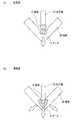
タンデムガスシールドアーク溶接方法は、溶接部にシールドガスを噴射しながら、先行極と後行極とからなる2つの電極によって溶接を行う方法である。従来のタンデム溶接では、例えば図1(a)に示すように、先行極10と後行極20とに同種のワイヤと同種のシールドガスGを用いて溶接を行うものもあったが、本発明は、図1(b)に示すように、先行極10と後行極20とにそれぞれ別のワイヤと別のシールドガスG1,G2を用いて溶接を行う。The tandem gas shielded arc welding method is a method in which welding is performed with two electrodes including a leading electrode and a trailing electrode while spraying a shielding gas to a welded portion. In conventional tandem welding, for example, as shown in FIG. 1 (a), there is one in which welding is performed on the leading
ここで、タンデム溶接では、低スパッタや美麗なビード形成を実現させるために、先行極10と後行極20とで安定な溶滴移行形態を維持することが極めて重要である。一方、タンデム溶接では、後行極20よりも先行極10のほうが溶込みに大きく影響するため、本発明では、先行極10のシールドガスG1として深溶込み性のある100%炭酸ガスを用いるが、これまで安価なソリッドワイヤを用いて逆極性溶接でも安定なスプレー移行を維持できる方法は見出されていない。Here, in tandem welding, in order to realize low spatter and beautiful bead formation, it is extremely important to maintain a stable droplet transfer form between the leading
図2(a)および図3(a)に示すように、一般的な100%炭酸ガス溶接では、アルゴンガスやアルゴンガスを主成分とする混合ガスを用いる場合と異なり、アークAが溶滴D周りから発生せず、溶滴Dの下から発生する。そうすると、図2(a)に示すように、溶滴Dが離脱し難くなり粗大となるため、グロビュール移行と呼ばれる移行形態になる。グロビュール移行になると、緊縮して高まったアーク力により押し上げられた溶滴Dが周囲に飛散し、多量のスパッタが発生してしまうが、タンデム溶接では、これがさらに助長されて極めて多量のスパッタを発生させるため、実施工で適用されることは皆無であった。なお、前記したグロビュール移行とは、図2(a)に示すように、溶滴Dが先行極10のワイヤ径を超える大きさで移行することをいう。 As shown in FIG. 2A and FIG. 3A, in general 100% carbon dioxide gas welding, arc A is a droplet D, unlike the case of using argon gas or a mixed gas containing argon gas as a main component. It does not occur from the surroundings, but from below the droplet D. Then, as shown in FIG. 2A, since the droplet D is difficult to be separated and becomes coarse, a transition form called globule transition is obtained. In the globule transition, the droplet D pushed up by the tightly increased arc force scatters to the surroundings and a large amount of spatter is generated. In tandem welding, this is further promoted and a very large amount of spatter is generated. Therefore, it was never applied in the construction work. The above-described globule transition means that the droplet D moves with a size exceeding the wire diameter of the leading
一方、図2(b)に示すように、アルゴンガスやアルゴンガスを主成分とする混合ガスによるタンデム溶接では、アークAが溶滴Dの周りから発生し、このアークAによる電磁ピンチ力によって溶滴Dが離脱し易くなるため、安定なスプレー移行を維持することができる。しかしながら、溶込みが浅いという問題がある。なお、前記したスプレー移行とは、図2(b)に示すように、溶滴Dが先行極10のワイヤ径以下の大きさで移行することをいう。 On the other hand, as shown in FIG. 2B, in tandem welding with argon gas or a mixed gas containing argon gas as a main component, an arc A is generated around the droplet D and is melted by an electromagnetic pinch force generated by the arc A. Since the droplets D are easily detached, stable spray transfer can be maintained. However, there is a problem that the penetration is shallow. Note that the above-described spray transfer means that the droplet D moves with a size equal to or smaller than the wire diameter of the leading
そこで、本発明者らは鋭意検討を重ね、先行極10のシールドガスG1として100%炭酸ガスを用い、図3(b)に示すように、母材Wを掘下げるようにアークAを発生させることによって、溶滴Dと開先壁面間でアークAを発生させ、溶滴Dの周りを包むように形成させることでその電磁ピンチ力によって溶滴Dを離脱させやすくすると、逆極性溶接した場合であってもスプレー移行が可能となること、また、電流に対する電圧の比を制限することで同時に深溶込み性をも得られることを見出した。そして、これら溶接条件の基本要件を見出し、かつ、低コスト、低スパッタ、深溶込み性等の要件も満たしたタンデムガスシールドアーク溶接方法を考案した。以下、考案した内容について詳しく説明する。Accordingly, the present inventors have conducted extensive studies, using a shielding gas G1 as 100% carbon dioxide of the leading
(先行極)
本発明の実施形態に係るタンデムガスシールドアーク溶接方法では、先行極10として安価なソリッドワイヤを用い、先行極10のシールドガスG1として安価な100%炭酸ガスを用いて逆極性溶接を行う。また、本発明の実施形態に係るタンデムガスシールドアーク溶接方法では、先行極10の溶接条件における溶接電流I[A]、溶接電圧V[V]、ワイヤ送給速度Wf[m/min]、ワイヤ半径r[m]が、以下の式(1)の関係を満たすようにする。(Leading pole)
The tandem gas-shielded arc welding method according to an embodiment of the present invention, an inexpensive solid wire as the leading
ここで、式(1)における「I・V」は、ワイヤ、すなわち先行極10を溶かすために必要なエネルギー量を示している。また、式(1)における「Wf・πr2」は、一分間当たりに送給されるワイヤ、すなわち先行極10の体積を示している。式(1)では必要なエネルギー量と体積の関係を制限し、式(2)はさらにエネルギー量に影響する電流と電圧の関係を制限する。上記式(1)と式(2)を満たすことで、図3(b)のように、100%炭酸ガス溶接でもスプレー移行させることができ、低スパッタと深溶込みタンデム溶接を実現できる。Here, “IV” in the equation (1) indicates the amount of energy necessary for melting the wire, that is, the leading
式(1)について説明する。式(1)値の上下限を設定しており、「(I・V・10−8)/(Wf・πr2)」の値が10.00を超えると、100%炭酸ガス溶接においてスプレー移行させることができなくなり、低スパッタ溶接を実現できなくなる。例えば、溶接電流I[A]が過大になると、アーク力も強くなる。過大なアーク力によってプールの安定性が劣化し、2つの電極間の湯溜まりも安定しなくなる。従って、多量なスパッタが生じるとともに、ビード形状も悪くなる。また、溶接電圧V[V]が過大になると、スプレー移行を維持できなくなり、グロビュール移行によって多量のスパッタが発生することになる。Formula (1) is demonstrated. And setting the upper and lower limits of the formula (1) value, the value of"(I · V · 10 -8) / (W f · πr 2) " is more than 10.00, spray at 100% carbon dioxide gas welding It becomes impossible to shift and low spatter welding cannot be realized. For example, when the welding current I [A] becomes excessive, the arc force also increases. Due to the excessive arc force, the stability of the pool deteriorates and the hot water pool between the two electrodes becomes unstable. Therefore, a large amount of spatter is generated and the bead shape is also deteriorated. Further, when the welding voltage V [V] is excessive, spray transfer cannot be maintained, and a large amount of spatter is generated by the globule transfer.
また、式(1)に示すように、「(I・V・10−8)/(Wf・πr2)」の値が5.00未満となると、100%炭酸ガス溶接においても溶込み深さが確保できなくなる上、低スパッタ溶接を実現できなくなる。例えば、溶接電流I[A]が過小になると、アーク力が弱くなり、溶込みも浅くなる。また、溶滴Dに作用する電磁ピンチ力が不足するため、スプレー移行が維持できなくなり、スパッタが多発する。さらに、溶接電圧V[V]が過小になると、ワイヤおよび母材Wを溶かすため必要なエネルギーが足りなくなり、短絡が生じ、溶込みが浅くなる上、スパッタも多量に発生する。Further, as shown in the formula (1), when the value of “(I · V · 10−8 ) / (Wf · πr2 )” is less than 5.00, the penetration depth is also obtained in 100% carbon dioxide welding. Cannot be secured, and low spatter welding cannot be realized. For example, when the welding current I [A] becomes too small, the arc force becomes weak and the penetration becomes shallow. Further, since the electromagnetic pinch force acting on the droplet D is insufficient, spray transfer cannot be maintained, and spatter frequently occurs. Further, when the welding voltage V [V] is too low, the energy required for melting the wire and the base material W becomes insufficient, a short circuit occurs, the penetration becomes shallow, and a large amount of spatter is generated.
また、本発明の実施形態に係るタンデムガスシールドアーク溶接方法では、図1(b)に示すように、溶込みを深くするために、先行極10のアーク長を短く維持する必要がある。従って、本発明の実施形態に係るタンデムガスシールドアーク溶接方法では、前記した式(1)に加えて、先行極10の溶接条件における溶接電流I[A]、溶接電圧V[V]が式(2)の関係を満たすようにする。 Further, in the tandem gas shielded arc welding method according to the embodiment of the present invention, as shown in FIG. 1B, it is necessary to keep the arc length of the leading
すなわち、溶接電流I[A]が不足し、式(2)の値が4.50未満であると、溶込みが浅くなる上、スプレー移行が維持できなくなる。また、溶接電圧V[V]が過大となり、式(2)の値が4.50未満であると、スプレー移行を維持できなくなり、グロビュール移行によって多量のスパッタが発生することになる。 That is, when the welding current I [A] is insufficient and the value of the expression (2) is less than 4.50, the penetration becomes shallow and the spray transfer cannot be maintained. Further, when the welding voltage V [V] is excessive and the value of the expression (2) is less than 4.50, the spray transfer cannot be maintained, and a large amount of spatter is generated by the globule transfer.
(後行極)
本発明の実施形態に係るタンデムガスシールドアーク溶接方法では、後行極20として安価なソリッドワイヤ、あるいは、フラックス入りワイヤを用い、後行極20のシールドガスG2としてアルゴンガスを60体積%以上含有するアルゴンと炭酸ガスを含む混合ガスを用いて逆極性溶接を行う。(Following pole)
The tandem gas-shielded arc welding method according to an embodiment of the present invention, an inexpensive solid wire as the trailing electrode 20, or, using a flux cored wire, and
また、先行極10の溶接条件を規定した前記した式(1)および式(2)を満たすことで、深溶込み化を図りつつ先行極10から発生するスパッタを大幅に低減できる効果があるが、タンデムガスシールドアーク溶接法において先行極10のみ規定しても、これに対して後行極20の溶接条件が不適であれば、ビード形状が不整となる上、後行極20から発生するスパッタが多発することになる。従って、本発明の実施形態に係るタンデムガスシールドアーク溶接方法では、先行極10の溶接条件を調整することに加えて、後行極20の溶接条件における溶接電流I[A]、溶接電圧V[V]、ワイヤ送給速度Wf[m/min]、ワイヤ半径r[m]が、以下の式(3)と式(4)の関係を満たすようにする。このように、式(3)と式(4)を満たすように後行極20の溶接条件を調整することで、当該後行極20のアーク長を適正に保つことができ、ビード形状を整えて低スパッタを実現することができる。Further, by satisfying the above-described formulas (1) and (2) that define the welding conditions of the leading
式(3)に示すように、(I・V・10−8)/(Wf・πr2)」の値が7.00を超えると、低スパッタかつ正常ビード形状が得られない。すなわち、溶接電流I[A]が大きすぎると後行アークのアーク力が高すぎるため、2つの電極間に生じる湯溜りが不安定になり、正常ビードが得られない。また、溶接電圧V[V]が大きすぎると、アーク長が長すぎるため、多量なスパッタが発生する。また、4.00未満になっても、低スパッタかつ正常ビード形状が得られない。すなわち、溶接電流I[A]が小さすぎると十分な電磁ピンチ力が得られないため、グロビュール移行となり、後行極20から発生するスパッタが増大する。また、後行アークのアーク力が低すぎるため、先行極10で形成した溶融池を十分に押し広げることができず、不整ビードとなる。更に、溶接電圧V[V]が小さすぎると、アーク長が短かすぎて短絡を発生させてしまい、スパッタも多発する上、ビード形状を十分に整えることができない。As shown in the formula (3), when the value of (I · V · 10−8 ) / (Wf · πr2 ) ”exceeds 7.00, a low spatter and a normal bead shape cannot be obtained. That is, if the welding current I [A] is too large, the arc force of the trailing arc is too high, so that the hot water pool generated between the two electrodes becomes unstable and a normal bead cannot be obtained. On the other hand, if the welding voltage V [V] is too large, the arc length is too long, and a large amount of spatter is generated. Moreover, even if it becomes less than 4.00, a low spatter and a normal bead shape cannot be obtained. That is, if the welding current I [A] is too small, a sufficient electromagnetic pinch force cannot be obtained, so that globule transition occurs and spatter generated from the trailing electrode 20 increases. Further, since the arc force of the trailing arc is too low, the molten pool formed by the leading
なお、式(4)に示すように、「(I2・10−3)/V」の上限値を8.00とした理由は、「(I2・10−3)/V」の値が8.00を超えると、溶接電圧が小さすぎて、先行極10によって凸になるビード形状を十分に整えることができないためである。As shown in equation (4), the reason why the upper limit value of “(I2 · 10−3 ) / V” is 8.00 is that the value of “(I2 · 10−3 ) / V” is If it exceeds 8.00, the welding voltage is too small, and the bead shape protruding by the leading
以上説明した本発明の実施形態に係るタンデムガスシールをアーク溶接方法は、前記した式(1)および式(2)を満たすように先行極10の溶接条件を調整することで、当該先行極10のシールドガスG1として炭酸ガスを用い、逆極性溶接でも安定なスプレー移行を維持することができ、深溶込み化しつつスパッタを大幅に低減できることができる。そして、本発明に係るタンデムガスシールドアーク溶接方法は、式(3)および式(4)を満たすように後行極20の溶接条件を調整することで、ビード形状を整えて、低スパッタを実現することができる。In the arc welding method for the tandem gas seal according to the embodiment of the present invention described above, the leading
従って、本発明の実施形態に係るタンデムガスシールドアーク溶接方法によれば、先行極10および後行極20の溶接条件をそれぞれ調整することで、先行極10に100%炭酸ガスを用いているにも関わらず、低スパッタを実現し、さらに溶込みも深くすることができる。また、本発明に係るタンデムガスシールドアーク溶接方法によれば、先行極10として安価なソリッドワイヤを用い、当該先行極10のシールドガスG1として安価な炭酸ガスを用いることで、コストを大幅に削減することができ、溶接工程の高品質・能率化を実現することができる。Therefore, according to the tandem gas shielded arc welding method according to the embodiment of the present invention, 100% carbon dioxide gas is used for the leading
また、本発明の実施形態に係るタンデムガスシールドアーク溶接方法は、先行極10のワイヤ直径a[mm]をa≦2.0とし、後行極20のワイヤ直径b[mm]をb≦(a−0.2)とすることが好ましい。これにより、本発明の実施形態に係るタンデムガスシールドアーク溶接方法は、所定以上の径を有するワイヤを先行極10として用いることで、溶接電流I[A]を高くすることができ、先行極10よりも径が細いワイヤを後行極20として用いることで、溶着量を増加させることができる。 In the tandem gas shielded arc welding method according to the embodiment of the present invention, the wire diameter a [mm] of the leading
以下、本発明の実施形態に係るタンデムガスシールドアーク溶接方法について、本発明の要件を満たす実施例と、本発明の要件を満たさない比較例と、を対比しながら説明する。 Hereinafter, the tandem gas shielded arc welding method according to the embodiment of the present invention will be described by comparing an example that satisfies the requirements of the present invention with a comparative example that does not satisfy the requirements of the present invention.
まず、第1の実験として、先行極10と後行極20の溶接条件を変更しながらタンデム溶接を行い、溶接条件ごとのスパッタ発生量を評価した。本実験では、先行極10としてソリッドワイヤを用い、後行極20としてフラックス入りワイヤを用いた。また、先行極10のシールドガスG1として炭酸ガスを用い、後行極20のシールドガスG2としてAr−10〜30%CO2ガス、すなわちアルゴンガスを60体積%以上含有するアルゴン炭酸混合ガスを用いた。また、先行極10と後行極20との極間距離を30mm、溶接速度を80cm/minとし、下向すみ肉溶接を行った。また、本実験では、先行極10および後行極20の極性は逆極性とした。以上のような条件下でタンデム溶接を行った結果を表1および表2に示す。First, as a first experiment, tandem welding was performed while changing the welding conditions of the leading
本実験では、具体的には表1および表2に示すように、先行極10のワイヤ送給速度を4.0〜28.0m/minの間で変化させ、ワイヤ直径を1.2〜2.0mmの間で変化させ、溶接電流を200〜650Aの間で変化させ、溶接電圧を16.0〜49.0Vの間で変化させながらタンデム溶接を行った。そして、表1に示すように、溶接条件ごとに前記した式(1)および式(2)の値を計算した。 In this experiment, specifically, as shown in Tables 1 and 2, the wire feed speed of the leading
また、本実験では、具体的は表1および表2に示すように、後行極20のワイヤ送給速度を13〜30m/minの間で変化させ、後行極20のワイヤ直径を1.0〜1.6mmの間で変化させ、溶接電流を255〜630Aの間で変化させ、溶接電圧を18.0〜49.0Vの間で変化させながらタンデム溶接を行った。そして、表2に示すように、溶接条件ごとに前記した式(3)および式(4)の値を計算した。 Further, in this experiment, specifically, as shown in Table 1 and Table 2, the wire feeding speed of the trailing electrode 20 is changed between 13 to 30 m / min, and the wire diameter of the trailing electrode 20 is set to 1. Tandem welding was performed while changing the welding current between 255 and 630 A and changing the welding voltage between 18.0 and 49.0 V. Then, as shown in Table 2, the values of Equation (3) and Equation (4) described above were calculated for each welding condition.
また、本実験では、表1および表2に示すそれぞれの溶接条件で溶接を行った場合のスパッタ発生量を評価し、表1および表2に示すように、スパッタがほとんど発生していない状態(0.7g/min以下の場合)を「◎(良好である)」と評価し、多量のスパッタが発生している状態(0.7g/minを超える場合)を「×(不良である)」と評価した。また、本実験では、溶接後のビード形状についても評価し、ビード形状がフラットである場合を「◎(良好である)」と評価し、ビード形状が凸となっている状態を「×(不良である)」と評価した。そして、スパッタ発生量とビード形状の両方が良好である場合を総合評価「◎」とし、スパッタ発生量とビード形状のいずれかが不良である場合を総合評価「×」とした。 Further, in this experiment, the amount of spatter generated when welding was performed under the respective welding conditions shown in Tables 1 and 2 was evaluated. As shown in Tables 1 and 2, almost no spatter was generated ( (In the case of 0.7 g / min or less) is evaluated as “良好 (good)”, and a state where a large amount of spatter is generated (in the case of exceeding 0.7 g / min) is indicated as “× (defect)”. It was evaluated. In this experiment, the bead shape after welding was also evaluated, the case where the bead shape was flat was evaluated as “「 (good) ”, and the bead shape was convex as“ × (defect). ”). A case where both the spatter generation amount and the bead shape were good was evaluated as “総 合”, and a case where either the spatter generation amount or the bead shape was defective was evaluated as “×”.
No.2,3,6〜11,14〜26,28,31〜34,43,44,47,48,52,53,56,57,60〜62,65,66,69,70,73,74,77,78,81,84,86,87は、表1および表2に示すように、いずれも式(1)の計算値が5.00以上10.00以下であり、かつ、式(2)の計算値が4.50以上であった。また、いずれも式(3)の計算値が4.00以上7.00以下であり、かつ、式(4)の計算値が8.00以下であった。従って、これらの溶接条件で溶接を行った場合、いずれもスパッタ発生量が少なく、かつ、ビード形状も良好であり、総合評価は「◎」となった。なお、No.86,87は、後行極20のシールドガスを、それぞれAr−30%CO2およびAr−10%CO2とした場合の実施例である。No. 2, 3, 6-11, 14-26, 28, 31-34, 43, 44, 47, 48, 52, 53, 56, 57, 60-62, 65, 66, 69, 70, 73, 74, 77, 78, 81, 84, 86, and 87, as shown in Table 1 and Table 2, all of the calculated values of Formula (1) are 5.00 or more and 10.00 or less, and Formula (2) The calculated value was 4.50 or more. In all cases, the calculated value of the formula (3) was 4.00 or more and 7.00 or less, and the calculated value of the formula (4) was 8.00 or less. Therefore, when welding was performed under these welding conditions, the spatter generation amount was small and the bead shape was good, and the overall evaluation was “◎”. In addition, No. 86 and 87 are examples when the shielding gas of the trailing electrode 20 is Ar-30% CO2 and Ar-10% CO2 , respectively.
一方、No.1は、表1に示すように、式(1)の計算値が10.00を超えており、式(4)の計算値が8.00を超えているため、多量のスパッタが発生するとともにビード形状も不良であった。従って、No.1は、表1に示すように、スパッタ発生評価、ビード形状および総合評価が「×」となった。また、No.4は、表1に示すように、式(1)の計算値が5.00未満であり、式(3)の計算値が4.00未満であり、式(4)の結果が8.00を超えているため、多量のスパッタが発生するとともにビード形状も不良であった。従って、No.4は、表1に示すように、スパッタ発生評価、ビード形状および総合評価が「×」となった。 On the other hand, no. As shown in Table 1, the calculated value of Equation (1) exceeds 10.00, and the calculated value of Equation (4) exceeds 8.00, so that a large amount of spatter is generated. The bead shape was also poor. Therefore, no. In Table 1, as shown in Table 1, the sputter generation evaluation, the bead shape, and the overall evaluation were “x”. No. 4, as shown in Table 1, the calculated value of the formula (1) is less than 5.00, the calculated value of the formula (3) is less than 4.00, and the result of the formula (4) is 8.00. Therefore, a large amount of spatter was generated and the bead shape was poor. Therefore, no. In Table 4, as shown in Table 1, the sputter generation evaluation, the bead shape, and the overall evaluation were “x”.
No.13は、表1に示すように、式(1)の計算値が10.00以上であるため、多量のスパッタが発生した。従って、No.13は、表1に示すように、スパッタ発生評価および総合評価が「×」となった。また、No.5,29,30は、表1に示すように、いずれも式(1)の計算値が5.00未満であるため、多量のスパッタが発生した。従って、No.5,29,30は、表1に示すように、スパッタ発生評価および総合評価が「×」となった。また、No.12,27は、表1に示すように、いずれも式(1)の計算値が10.00を超えており、式(2)の計算値が4.50未満であるため、多量のスパッタが発生した。従って、No.12,27は、表1に示すように、スパッタ発生評価および総合評価が「×」となった。 No. No. 13, as shown in Table 1, a large amount of spatter occurred because the calculated value of the formula (1) was 10.00 or more. Therefore, no. No. 13, as shown in Table 1, the sputter generation evaluation and the overall evaluation were “x”. No. As shown in Table 1, all of Nos. 5, 29, and 30 have a calculated value of the formula (1) of less than 5.00, so a large amount of spatter occurred. Therefore, no. As shown in Table 1, Nos. 5, 29, and 30 were evaluated as “×” in sputter generation evaluation and overall evaluation. No. 12 and 27, as shown in Table 1, since the calculated value of the formula (1) exceeds 10.00 and the calculated value of the formula (2) is less than 4.50, a large amount of spatter is generated. Occurred. Therefore, no. In Tables 12 and 27, as shown in Table 1, the sputter generation evaluation and the overall evaluation were “x”.
No.35,37〜41は、表1に示すように、いずれも式(2)の計算値が4.50未満であるため、多量のスパッタが発生した。従って、No.35,37〜41は、表1に示すように、スパッタ発生評価および総合評価が「×」となった。また、No.36は、表1に示すように、式(1)の計算値が5.00未満であり、式(2)の計算値が4.50未満であるため、多量のスパッタが発生した。従って、No.36は、表1に示すように、スパッタ発生評価および総合評価が「×」となった。なお、表1において、式(1)または式(2)を満たさないものは、下線かつ太字で示している。 No. 35 and 37 to 41, as shown in Table 1, all had a calculated value of the formula (2) of less than 4.50, so a large amount of spatter occurred. Therefore, no. 35 and 37 to 41, as shown in Table 1, the sputter generation evaluation and the overall evaluation were “x”. No. As shown in Table 1, since the calculated value of the formula (1) was less than 5.00 and the calculated value of the formula (2) was less than 4.50, a large amount of spatter occurred. Therefore, no. In Table 36, as shown in Table 1, the sputter generation evaluation and the overall evaluation were “x”. In Table 1, those that do not satisfy Formula (1) or Formula (2) are underlined and bold.
No.42,46,51,55,59,64,72,76,80,83は、表2に示すように、いずれも式(3)の計算値が7.00を超えているため、多量のスパッタが発生し、ビード形状も不良であった。従って、No.42,46,51,55,59,64,72,76,80,83は、表2に示すように、スパッタ発生評価、ビード形状評価および総合評価が「×」となった。また、No.45,54,58,63,67,75,79,82,85は、表2に示すように、いずれも式(3)の計算値が4.00未満であるため、多量のスパッタが発生し、ビード形状も不良であった。従って、No.45,54,58,63,67,75,79,82,85は、表2に示すように、スパッタ発生評価、ビード形状評価および総合評価が「×」となった。 No. 42, 46, 51, 55, 59, 64, 72, 76, 80, and 83, as shown in Table 2, all have a calculated value of Equation (3) exceeding 7.00. And the bead shape was poor. Therefore, no. In Tables 42, 46, 51, 55, 59, 64, 72, 76, 80, and 83, as shown in Table 2, the sputter generation evaluation, the bead shape evaluation, and the overall evaluation were “x”. No. As shown in Table 2, 45, 54, 58, 63, 67, 75, 79, 82, and 85 all have a calculated value of Equation (3) of less than 4.00, so a large amount of spatter is generated. The bead shape was also poor. Therefore, no. 45, 54, 58, 63, 67, 75, 79, 82, and 85, as shown in Table 2, the sputter generation evaluation, the bead shape evaluation, and the overall evaluation were “x”.
No.49,50は、表2に示すように、いずれも式(3)の計算値が4.00未満であり、式(4)の計算値が8.00を超えているため、多量のスパッタが発生し、ビード形状も不良であった。従って、No.49,50は、表2に示すように、スパッタ発生評価、ビード形状評価および総合評価が「×」となった。また、No.68,71は、表2に示すように、いずれも式(4)の計算値が8.00を超えているため、ビード形状が不良であった。従って、No.68,71は、表2に示すように、ビード形状および総合評価が「×」となった。なお、表2において、式(3)または式(4)を満たさないものは、下線かつ太字で示している。 No. 49 and 50, as shown in Table 2, since the calculated value of the formula (3) is less than 4.00 and the calculated value of the formula (4) exceeds 8.00, a large amount of spatter is generated. The bead shape was poor. Therefore, no. In Tables 49 and 50, as shown in Table 2, the sputter generation evaluation, the bead shape evaluation, and the overall evaluation were “x”. No. 68 and 71, as shown in Table 2, since the calculated value of Equation (4) exceeded 8.00, the bead shape was poor. Therefore, no. As for 68 and 71, as shown in Table 2, the bead shape and the comprehensive evaluation were “x”. In Table 2, those that do not satisfy Expression (3) or Expression (4) are underlined and bold.
No.88は、表2に示すように、後行極20は式(3)と式(4)を満たしているが、正極性であるため、多量のスパッタが発生し、ビード形状も不良であった。従って、No.88は、表2に示すように、スパッタ発生評価、ビード形状評価および総合評価が「×」となった。また、No.89は、表2に示すように、先行極10は式(1)と式(2)を満たしているが、正極性であるため、多量のスパッタが発生し、ビード形状も不良であった。従って、No.89は、表2に示すように、スパッタ発生評価、ビード形状評価および総合評価が「×」となった。また、No.90は、表2に示すように、先行極10は式(1)と式(2)を満たしており、後行極20は式(3)と式(4)を満たしているが、ともに正極性であるため、多量のスパッタが発生し、ビード形状も不良であった。従って、No.90は、表2に示すように、スパッタ発生評価、ビード形状評価および総合評価が「×」となった。 No. 88, as shown in Table 2, the trailing electrode 20 satisfies the formulas (3) and (4), but because of the positive polarity, a large amount of spatter was generated and the bead shape was poor. . Therefore, no. In Table 88, as shown in Table 2, the sputter generation evaluation, the bead shape evaluation, and the overall evaluation were “x”. No. 89, as shown in Table 2, the leading
次に、第2の実験として、本発明の要件を満たさない従来法によるタンデム溶接と、本発明の要件を満たす発明法によるタンデム溶接と、をそれぞれ同脚長下向すみ溶接で、母材Wに対する溶込みの比較と、スパッタ発生量の比較と、を行った。本実験では、従来法と発明法について、具体的には表3に示す条件でタンデム溶接を行った。なお、表3における発明法の溶接条件は、前記した式(1)、式(2)、式(3)および式(4)を満たしている。そして、本実験では、先行極10および後行極20の極性は逆極性とした。 Next, as a second experiment, tandem welding according to the conventional method that does not satisfy the requirements of the present invention and tandem welding according to the method of the present invention that satisfies the requirements of the present invention are respectively applied to the base metal W by downwardly facing the same leg length. Comparison of penetration and comparison of spatter generation amount were performed. In this experiment, tandem welding was performed under the conditions shown in Table 3 for the conventional method and the inventive method. In addition, the welding conditions of the invention method in Table 3 satisfy the above-described formulas (1), (2), (3), and (4). In this experiment, the polarities of the leading
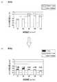
図4は、従来法と発明法とのそれぞれにおける、溶接速度ごとの溶込みの深さを示すグラフである。図4に示すように、発明法によってタンデム溶接を行った場合、いずれの溶接速度の場合であっても、従来法よりも溶込みを14%(溶接速度:70cm/min)から40%(溶接速度:110cm/min)まで深くできることが分かる。また、溶込み深さ3.5mmを確保するのに従来法では溶接速度70cm/minでも不十分であるが、本発明では、溶接速度110cm/minまで増加させても3.5mmを確保できており、深溶込み化による溶接能率向上も達成できる。 FIG. 4 is a graph showing the depth of penetration for each welding speed in each of the conventional method and the invention method. As shown in FIG. 4, when tandem welding is performed by the inventive method, the penetration is 14% (welding speed: 70 cm / min) to 40% (welding) compared to the conventional method at any welding speed. It turns out that it can deepen to (speed: 110 cm / min). Further, in order to secure a penetration depth of 3.5 mm, the conventional method is insufficient even at a welding speed of 70 cm / min, but in the present invention, even if the welding speed is increased to 110 cm / min, 3.5 mm can be secured. Therefore, the welding efficiency can be improved by deep penetration.
また、図5(a)は、従来法における溶接速度ごとのスパッタ発生量を示すグラフであり、図5(b)は、発明法における溶接速度ごとのスパッタ発生量を示すグラフである。そして、この図5(a)、(b)において色分けされた領域は、大きさの異なるスパッタの割合を示している。すなわち、図5(a)では、2種類の大きさのスパッタが色分けして示されており、図5(b)では、3種類の大きさのスパッタが色分けして示されている。 FIG. 5A is a graph showing the amount of spatter generated for each welding speed in the conventional method, and FIG. 5B is a graph showing the amount of spatter generated for each welding speed in the inventive method. The regions color-coded in FIGS. 5A and 5B show the proportions of spatters having different sizes. That is, in FIG. 5A, two kinds of spatters are shown in different colors, and in FIG. 5B, three kinds of spatters are shown in different colors.
図5(a)、(b)に示すように、発明法によってタンデム溶接を行うことで、従来法と比較してスパッタ量を大幅に抑制できることがわかる。具体的には、図5(b)に示すように、溶接速度が70cm/minの場合はスパッタ量を32%減少させることができ、溶接速度が80cm/minの場合はスパッタ量を24%減少させることができ、溶接速度が90cm/minの場合はスパッタ量を59%減少させることができ、溶接速度が100cm/minの場合はスパッタ量を61%減少させることができ、溶接速度が110cm/minの場合はスパッタ量を66%減少させることができる。 As shown in FIGS. 5 (a) and 5 (b), it can be seen that the amount of sputtering can be significantly reduced by performing tandem welding by the inventive method as compared with the conventional method. Specifically, as shown in FIG. 5B, when the welding speed is 70 cm / min, the spatter amount can be reduced by 32%, and when the welding speed is 80 cm / min, the spatter amount is reduced by 24%. When the welding speed is 90 cm / min, the spatter amount can be reduced by 59%. When the welding speed is 100 cm / min, the spatter amount can be reduced by 61%, and the welding speed can be 110 cm / min. In the case of min, the amount of sputtering can be reduced by 66%.
以上のような2つの実験により、先行極10のシールドガスG1として炭酸ガスを用いたとしても、式(1)、式(2)、式(3)および式(4)を満たすように先行極10および後行極20の溶接条件を調整することで、スパッタの発生を抑制できることが確認できた。As a result of the above two experiments, even if carbon dioxide is used as the shielding gas G1 of the leading
以上、本発明の実施形態に係るタンデムガスシールドアーク溶接方法について、発明を実施するための形態および実施例により具体的に説明したが、本発明の趣旨はこれらの記載に限定されるものではなく、特許請求の範囲の記載に基づいて広く解釈されなければならない。また、これらの記載に基づいて種々変更、改変等したものも本発明の趣旨に含まれることはいうまでもない。 As described above, the tandem gas shielded arc welding method according to the embodiment of the present invention has been specifically described with reference to the modes and examples for carrying out the invention, but the gist of the present invention is not limited to these descriptions. Should be construed broadly based on the claims. Needless to say, various changes and modifications based on these descriptions are also included in the spirit of the present invention.
10 先行極
20 後行極
A アーク
D 溶滴
G,G1,G2 シールドガス
W 母材10 Leading electrode 20 Trailing electrode A Arc D Droplet G, G1 , G2 Shield gas W Base material
Claims (1)
Translated fromJapanese前記先行極としてソリッドワイヤを用いるとともに、当該先行極のシールドガスとして炭酸ガスを用い、
前記後行極としてソリッドワイヤまたはフラックス入りワイヤを用いるとともに、当該後行極のシールドガスとしてアルゴンガスを60体積%以上含有するアルゴン炭酸混合ガスを用い、
前記先行極と前記後行極をともに逆極性とし、
前記先行極の溶接条件における溶接電流I[A]、溶接電圧V[V]、ワイヤ送給速度Wf[m/min]、ワイヤ半径r[m]が、以下の式(1)および式(2)の関係を満たし、
前記後行極の溶接条件における溶接電流I[A]、溶接電圧V[V]が、以下の式(3)および式(4)の関係を満たし、
前記先行極のワイヤ直径a[mm]は、a≦2.0であり、
前記後行極のワイヤ直径b[mm]は、b≦(a−0.2)であることを特徴とするタンデムガスシールドアーク溶接方法。
Using a solid wire as the leading electrode, and using carbon dioxide gas as the shielding gas of the leading electrode,
Using a solid wire or a flux-cored wire as the trailing electrode, and using an argon carbon dioxide mixed gas containing 60% by volume or more of argon gas as a shielding gas for the trailing electrode,
Both the leading electrode and the trailing electrode have opposite polarities,
The welding current I [A], welding voltage V [V], wire feed speed Wf [m / min], and wire radius r [m] under the welding conditions of the leading electrode are expressed by the following equations (1) and (2). )
Welding current I [A] in the welding conditions of the trailing electrode, the welding voltage V [V] is,meets the relationship of the following equation (3) and(4),
The wire diameter a [mm] of the leading electrode is a ≦ 2.0,
A tandem gas shielded arc welding method,wherein the wire diameter b [mm] of the trailing electrode is b ≦ (a−0.2) .
Priority Applications (5)
| Application Number | Priority Date | Filing Date | Title |
|---|---|---|---|
| JP2012053590AJP5977965B2 (en) | 2012-03-09 | 2012-03-09 | Tandem gas shielded arc welding method |
| CN201310033899.2ACN103302384B (en) | 2012-03-09 | 2013-01-29 | Lap siding gas protection arc welding method |
| EP13000475.7AEP2636477B1 (en) | 2012-03-09 | 2013-01-31 | Tandem gas-shielded arc welding method |
| US13/765,818US9266197B2 (en) | 2012-03-09 | 2013-02-13 | Tandem gas-shielded arc welding method |
| KR1020130024633AKR101477893B1 (en) | 2012-03-09 | 2013-03-07 | Tandem gas-shielded arc welding method |
Applications Claiming Priority (1)
| Application Number | Priority Date | Filing Date | Title |
|---|---|---|---|
| JP2012053590AJP5977965B2 (en) | 2012-03-09 | 2012-03-09 | Tandem gas shielded arc welding method |
Publications (2)
| Publication Number | Publication Date |
|---|---|
| JP2013184212A JP2013184212A (en) | 2013-09-19 |
| JP5977965B2true JP5977965B2 (en) | 2016-08-24 |
Family
ID=47713811
Family Applications (1)
| Application Number | Title | Priority Date | Filing Date |
|---|---|---|---|
| JP2012053590AActiveJP5977965B2 (en) | 2012-03-09 | 2012-03-09 | Tandem gas shielded arc welding method |
Country Status (5)
| Country | Link |
|---|---|
| US (1) | US9266197B2 (en) |
| EP (1) | EP2636477B1 (en) |
| JP (1) | JP5977965B2 (en) |
| KR (1) | KR101477893B1 (en) |
| CN (1) | CN103302384B (en) |
Families Citing this family (3)
| Publication number | Priority date | Publication date | Assignee | Title |
|---|---|---|---|---|
| JP2017196653A (en)* | 2016-04-28 | 2017-11-02 | 株式会社神戸製鋼所 | Gas shield arc welding system and gas shield arc welding method |
| CN109226938B (en)* | 2017-07-10 | 2021-06-15 | 株式会社神户制钢所 | Multi-electrode gas shielded arc single-side welding method |
| JP6875232B2 (en)* | 2017-07-10 | 2021-05-19 | 株式会社神戸製鋼所 | Multi-electrode gas shield arc single-sided welding method |
Family Cites Families (25)
| Publication number | Priority date | Publication date | Assignee | Title |
|---|---|---|---|---|
| US3007033A (en)* | 1959-04-15 | 1961-10-31 | Union Carbide Corp | Inert gas shielded metal arc welding |
| JPS5161447A (en)* | 1974-11-26 | 1976-05-28 | Nippon Kokan Kk | Tadenkyokugasushiirudoaakuyosetsuho |
| JPS5236941B2 (en)* | 1974-11-26 | 1977-09-19 | ||
| GB1517097A (en)* | 1976-05-27 | 1978-07-12 | Nippon Kokan Kk | Method of multiple electrode gas shielded arc welding |
| SU1459849A1 (en)* | 1978-12-25 | 1989-02-23 | Предприятие П/Я А-3959 | Method of arc welding with consumable electrode |
| US4246463A (en)* | 1979-02-13 | 1981-01-20 | The Lincoln Electric Company | Method and apparatus for arc welding of metal plates from one side only |
| JPH03110070A (en)* | 1989-09-21 | 1991-05-10 | Matsumoto Kikai Kk | Method and equipment for consumable electrode automatic arc welding |
| JPH09206945A (en)* | 1996-02-05 | 1997-08-12 | Kobe Steel Ltd | Multi-electrode gas shielded one-side welding method |
| US6207929B1 (en)* | 1999-06-21 | 2001-03-27 | Lincoln Global, Inc. | Tandem electrode welder and method of welding with two electrodes |
| JP2003053545A (en) | 2001-08-07 | 2003-02-26 | Kobe Steel Ltd | Tandem arc welding method |
| WO2003064103A1 (en) | 2002-01-31 | 2003-08-07 | Jfe Steel Corporation | Steel wire for carbon dioxide shielded arc welding and welding process using the same |
| JP3945396B2 (en) | 2002-12-09 | 2007-07-18 | Jfeスチール株式会社 | Steel wire for carbon dioxide shielded arc welding and welding method using the same |
| US6847008B2 (en)* | 2003-01-17 | 2005-01-25 | Lincoln Global, Inc. | Electric arc welding system |
| US8895896B2 (en)* | 2004-01-12 | 2014-11-25 | Lincoln Global, Inc. | Modified series arc welding and improved control of one sided series arc welding |
| DE102005014969A1 (en)* | 2005-04-01 | 2006-10-05 | Linde Ag | Method of arc welding |
| CA2611260C (en)* | 2006-06-14 | 2011-07-19 | Matsushita Electric Industrial Co., Ltd. | Tandem arc welding device |
| CN100589914C (en)* | 2006-08-01 | 2010-02-17 | 株式会社神户制钢所 | Multi-electrode gas shielded arc welding method |
| JP4964025B2 (en) | 2006-08-01 | 2012-06-27 | 株式会社神戸製鋼所 | Multi-electrode gas shielded arc welding method |
| JP5345392B2 (en) | 2006-08-02 | 2013-11-20 | 大陽日酸株式会社 | Tandem gas metal arc welding method, welding torch and welding apparatus used therefor |
| CN101134260A (en)* | 2007-10-25 | 2008-03-05 | 上海交通大学 | Three wire open arc welding method |
| US8278587B2 (en)* | 2008-02-11 | 2012-10-02 | Adaptive Intelligent Systems, LLC | Systems and methods to modify gas metal arc welding and its variants |
| JP5228846B2 (en)* | 2008-11-28 | 2013-07-03 | Jfeスチール株式会社 | Tandem arc welding method |
| KR101329088B1 (en)* | 2009-02-27 | 2013-11-14 | 제이에프이 스틸 가부시키가이샤 | Complex method of welding in combination of gas-shield arc welding with submerged arc welding |
| JP5342280B2 (en)* | 2009-03-16 | 2013-11-13 | 株式会社神戸製鋼所 | Tandem pulse arc welding control apparatus and system |
| JP5260469B2 (en)* | 2009-10-26 | 2013-08-14 | 株式会社神戸製鋼所 | Gas shield arc welding method |
- 2012
- 2012-03-09JPJP2012053590Apatent/JP5977965B2/enactiveActive
- 2013
- 2013-01-29CNCN201310033899.2Apatent/CN103302384B/enactiveActive
- 2013-01-31EPEP13000475.7Apatent/EP2636477B1/ennot_activeNot-in-force
- 2013-02-13USUS13/765,818patent/US9266197B2/ennot_activeExpired - Fee Related
- 2013-03-07KRKR1020130024633Apatent/KR101477893B1/ennot_activeExpired - Fee Related
Also Published As
| Publication number | Publication date |
|---|---|
| CN103302384B (en) | 2015-09-23 |
| KR20130103412A (en) | 2013-09-23 |
| JP2013184212A (en) | 2013-09-19 |
| US9266197B2 (en) | 2016-02-23 |
| US20130233833A1 (en) | 2013-09-12 |
| CN103302384A (en) | 2013-09-18 |
| EP2636477A1 (en) | 2013-09-11 |
| KR101477893B1 (en) | 2014-12-30 |
| EP2636477B1 (en) | 2014-04-23 |
Similar Documents
| Publication | Publication Date | Title |
|---|---|---|
| JP6025627B2 (en) | Tandem gas shielded arc welding method | |
| JP5450221B2 (en) | High current density gas shielded arc welding method | |
| CN108067761B (en) | Welding electrode wire with alkaline earth metal | |
| JP2009255125A (en) | PURE Ar GAS SHIELDED WELDING MIG FLUX-CORED WIRE AND MIG ARC WELDING METHOD | |
| US11426824B2 (en) | Aluminum-containing welding electrode | |
| JP5826137B2 (en) | Tandem submerged arc welding method | |
| US9102013B2 (en) | Flux-cored welding wire for carbon steel and process for arc welding | |
| US10799974B2 (en) | Electrodes for forming austenitic and duplex steel weld metal | |
| JP5977965B2 (en) | Tandem gas shielded arc welding method | |
| KR102115725B1 (en) | Multi-electrode gas-shielded arc one-side welding method | |
| JP2007260692A (en) | Submerged arc welding method for thick steel plate | |
| JP5540391B2 (en) | GMA welding method | |
| KR102117815B1 (en) | Multi-electrode gas-shielded arc one-side welding method | |
| KR102424484B1 (en) | Tandem gas shield arc welding method and welding device | |
| KR101091469B1 (en) | MIX flux cored wire and MIX arc welding method for pure ARC shield gas welding | |
| KR102216814B1 (en) | Multi-electrode submerged arc welding method and welding device | |
| JP5218972B2 (en) | GMA welding method | |
| JP5228846B2 (en) | Tandem arc welding method | |
| JPH11226735A (en) | Gas shielded arc welding method | |
| JP4894145B2 (en) | Welding method using consumable electrode type welding wire used in high purity inert gas atmosphere | |
| KR20160035270A (en) | Electrogas Welding Method | |
| JP2009297738A (en) | Shielding gas for arc brazing and arc brazing method using the same | |
| JPS63154267A (en) | High-speed gas shielded arc welding method |
Legal Events
| Date | Code | Title | Description |
|---|---|---|---|
| A621 | Written request for application examination | Free format text:JAPANESE INTERMEDIATE CODE: A621 Effective date:20140901 | |
| A977 | Report on retrieval | Free format text:JAPANESE INTERMEDIATE CODE: A971007 Effective date:20150928 | |
| A131 | Notification of reasons for refusal | Free format text:JAPANESE INTERMEDIATE CODE: A131 Effective date:20150929 | |
| A02 | Decision of refusal | Free format text:JAPANESE INTERMEDIATE CODE: A02 Effective date:20160315 | |
| A521 | Written amendment | Free format text:JAPANESE INTERMEDIATE CODE: A523 Effective date:20160519 | |
| RD02 | Notification of acceptance of power of attorney | Free format text:JAPANESE INTERMEDIATE CODE: A7422 Effective date:20160531 | |
| A521 | Written amendment | Free format text:JAPANESE INTERMEDIATE CODE: A821 Effective date:20160520 | |
| A911 | Transfer to examiner for re-examination before appeal (zenchi) | Free format text:JAPANESE INTERMEDIATE CODE: A911 Effective date:20160614 | |
| TRDD | Decision of grant or rejection written | ||
| A01 | Written decision to grant a patent or to grant a registration (utility model) | Free format text:JAPANESE INTERMEDIATE CODE: A01 Effective date:20160719 | |
| A61 | First payment of annual fees (during grant procedure) | Free format text:JAPANESE INTERMEDIATE CODE: A61 Effective date:20160725 | |
| R150 | Certificate of patent or registration of utility model | Ref document number:5977965 Country of ref document:JP Free format text:JAPANESE INTERMEDIATE CODE: R150 |