JP5976647B2 - Degradation control of bioabsorbable metal implants - Google Patents
Degradation control of bioabsorbable metal implantsDownload PDFInfo
- Publication number
- JP5976647B2 JP5976647B2JP2013526035AJP2013526035AJP5976647B2JP 5976647 B2JP5976647 B2JP 5976647B2JP 2013526035 AJP2013526035 AJP 2013526035AJP 2013526035 AJP2013526035 AJP 2013526035AJP 5976647 B2JP5976647 B2JP 5976647B2
- Authority
- JP
- Japan
- Prior art keywords
- implant
- tissue
- metallic material
- fastener
- metal material
- Prior art date
- Legal status (The legal status is an assumption and is not a legal conclusion. Google has not performed a legal analysis and makes no representation as to the accuracy of the status listed.)
- Active
Links
- 239000007943implantSubstances0.000titleclaimsdescription133
- 230000015556catabolic processEffects0.000titleclaimsdescription17
- 238000006731degradation reactionMethods0.000titleclaimsdescription17
- 229910052751metalInorganic materials0.000titleclaimsdescription10
- 239000002184metalSubstances0.000titleclaimsdescription10
- 239000007769metal materialSubstances0.000claimsdescription50
- 229910045601alloyInorganic materials0.000claimsdescription10
- 239000000956alloySubstances0.000claimsdescription10
- 230000001788irregularEffects0.000claimsdescription4
- 239000000463materialSubstances0.000description95
- 210000001519tissueAnatomy0.000description40
- 238000000034methodMethods0.000description18
- 210000000988bone and boneAnatomy0.000description14
- XEEYBQQBJWHFJM-UHFFFAOYSA-NIronChemical compound[Fe]XEEYBQQBJWHFJM-UHFFFAOYSA-N0.000description10
- FYYHWMGAXLPEAU-UHFFFAOYSA-NMagnesiumChemical compound[Mg]FYYHWMGAXLPEAU-UHFFFAOYSA-N0.000description6
- 229910052749magnesiumInorganic materials0.000description6
- 239000011777magnesiumSubstances0.000description6
- 229910052742ironInorganic materials0.000description5
- 238000005452bendingMethods0.000description4
- 150000002739metalsChemical class0.000description4
- 230000008901benefitEffects0.000description3
- 238000000354decomposition reactionMethods0.000description3
- BQCADISMDOOEFD-UHFFFAOYSA-NSilverChemical compound[Ag]BQCADISMDOOEFD-UHFFFAOYSA-N0.000description2
- 210000001124body fluidAnatomy0.000description2
- 238000005260corrosionMethods0.000description2
- 230000007797corrosionEffects0.000description2
- 229910000510noble metalInorganic materials0.000description2
- 229910052709silverInorganic materials0.000description2
- 239000004332silverSubstances0.000description2
- 229910000861Mg alloyInorganic materials0.000description1
- 238000004026adhesive bondingMethods0.000description1
- 230000009286beneficial effectEffects0.000description1
- 239000010839body fluidSubstances0.000description1
- 230000001934delayEffects0.000description1
- 230000003111delayed effectEffects0.000description1
- 230000001066destructive effectEffects0.000description1
- 239000010432diamondSubstances0.000description1
- 230000003628erosive effectEffects0.000description1
- PCHJSUWPFVWCPO-UHFFFAOYSA-NgoldChemical compound[Au]PCHJSUWPFVWCPO-UHFFFAOYSA-N0.000description1
- 229910052737goldInorganic materials0.000description1
- 239000010931goldSubstances0.000description1
- 229910001092metal group alloyInorganic materials0.000description1
- 238000012986modificationMethods0.000description1
- 230000004048modificationEffects0.000description1
- 230000002093peripheral effectEffects0.000description1
- 229920000642polymerPolymers0.000description1
- 239000000126substanceSubstances0.000description1
- 238000003466weldingMethods0.000description1
- 229910052727yttriumInorganic materials0.000description1
- VWQVUPCCIRVNHF-UHFFFAOYSA-Nyttrium atomChemical compound[Y]VWQVUPCCIRVNHF-UHFFFAOYSA-N0.000description1
Images


Classifications
- A—HUMAN NECESSITIES
- A61—MEDICAL OR VETERINARY SCIENCE; HYGIENE
- A61B—DIAGNOSIS; SURGERY; IDENTIFICATION
- A61B17/00—Surgical instruments, devices or methods
- A61B17/56—Surgical instruments or methods for treatment of bones or joints; Devices specially adapted therefor
- A61B17/58—Surgical instruments or methods for treatment of bones or joints; Devices specially adapted therefor for osteosynthesis, e.g. bone plates, screws or setting implements
- A61B17/68—Internal fixation devices, including fasteners and spinal fixators, even if a part thereof projects from the skin
- A61B17/80—Cortical plates, i.e. bone plates; Instruments for holding or positioning cortical plates, or for compressing bones attached to cortical plates
- A—HUMAN NECESSITIES
- A61—MEDICAL OR VETERINARY SCIENCE; HYGIENE
- A61B—DIAGNOSIS; SURGERY; IDENTIFICATION
- A61B17/00—Surgical instruments, devices or methods
- A61B17/56—Surgical instruments or methods for treatment of bones or joints; Devices specially adapted therefor
- A61B17/58—Surgical instruments or methods for treatment of bones or joints; Devices specially adapted therefor for osteosynthesis, e.g. bone plates, screws or setting implements
- A61B17/68—Internal fixation devices, including fasteners and spinal fixators, even if a part thereof projects from the skin
- A61B17/84—Fasteners therefor or fasteners being internal fixation devices
- A61B17/86—Pins or screws or threaded wires; nuts therefor
- A—HUMAN NECESSITIES
- A61—MEDICAL OR VETERINARY SCIENCE; HYGIENE
- A61F—FILTERS IMPLANTABLE INTO BLOOD VESSELS; PROSTHESES; DEVICES PROVIDING PATENCY TO, OR PREVENTING COLLAPSING OF, TUBULAR STRUCTURES OF THE BODY, e.g. STENTS; ORTHOPAEDIC, NURSING OR CONTRACEPTIVE DEVICES; FOMENTATION; TREATMENT OR PROTECTION OF EYES OR EARS; BANDAGES, DRESSINGS OR ABSORBENT PADS; FIRST-AID KITS
- A61F2/00—Filters implantable into blood vessels; Prostheses, i.e. artificial substitutes or replacements for parts of the body; Appliances for connecting them with the body; Devices providing patency to, or preventing collapsing of, tubular structures of the body, e.g. stents
- A61F2/02—Prostheses implantable into the body
- A61F2/28—Bones
- A—HUMAN NECESSITIES
- A61—MEDICAL OR VETERINARY SCIENCE; HYGIENE
- A61L—METHODS OR APPARATUS FOR STERILISING MATERIALS OR OBJECTS IN GENERAL; DISINFECTION, STERILISATION OR DEODORISATION OF AIR; CHEMICAL ASPECTS OF BANDAGES, DRESSINGS, ABSORBENT PADS OR SURGICAL ARTICLES; MATERIALS FOR BANDAGES, DRESSINGS, ABSORBENT PADS OR SURGICAL ARTICLES
- A61L27/00—Materials for grafts or prostheses or for coating grafts or prostheses
- A61L27/02—Inorganic materials
- A61L27/04—Metals or alloys
- A—HUMAN NECESSITIES
- A61—MEDICAL OR VETERINARY SCIENCE; HYGIENE
- A61B—DIAGNOSIS; SURGERY; IDENTIFICATION
- A61B17/00—Surgical instruments, devices or methods
- A61B17/56—Surgical instruments or methods for treatment of bones or joints; Devices specially adapted therefor
- A61B17/58—Surgical instruments or methods for treatment of bones or joints; Devices specially adapted therefor for osteosynthesis, e.g. bone plates, screws or setting implements
- A61B17/68—Internal fixation devices, including fasteners and spinal fixators, even if a part thereof projects from the skin
- A61B17/84—Fasteners therefor or fasteners being internal fixation devices
- A61B17/86—Pins or screws or threaded wires; nuts therefor
- A61B17/866—Material or manufacture
Landscapes
- Health & Medical Sciences (AREA)
- Orthopedic Medicine & Surgery (AREA)
- Life Sciences & Earth Sciences (AREA)
- Surgery (AREA)
- Animal Behavior & Ethology (AREA)
- Veterinary Medicine (AREA)
- Public Health (AREA)
- General Health & Medical Sciences (AREA)
- Engineering & Computer Science (AREA)
- Heart & Thoracic Surgery (AREA)
- Biomedical Technology (AREA)
- Molecular Biology (AREA)
- Nuclear Medicine, Radiotherapy & Molecular Imaging (AREA)
- Neurology (AREA)
- Medical Informatics (AREA)
- Oral & Maxillofacial Surgery (AREA)
- Chemical & Material Sciences (AREA)
- Transplantation (AREA)
- Dermatology (AREA)
- Medicinal Chemistry (AREA)
- Inorganic Chemistry (AREA)
- Epidemiology (AREA)
- Cardiology (AREA)
- Vascular Medicine (AREA)
- Prostheses (AREA)
- Materials For Medical Uses (AREA)
- Surgical Instruments (AREA)
Description
Translated fromJapanese (関連出願の引用)
本願は、米国仮出願第61/378,747号(2010年8月31日出願)の利益を主張する。該出願は、その全体が参照により本明細書に引用される。(Citation of related application)
This application claims the benefit of US Provisional Application No. 61 / 378,747 (filed Aug. 31, 2010). The application is hereby incorporated by reference in its entirety.
本発明は、分解制御された金属インプラントおよびインプラントの分解を制御する方法に関する。The present invention relates to a degradation-controlled metalimplant and a method for controlling the degradation of animplant .
金属の場合、最も破壊的タイプの分解は、多くの場合、性質上、化学的であると考えられる電気化学またはガルバニック侵食から生じる。用語「分解」および「腐食」は、本明細書では、交換可能に使用される。 In the case of metals, the most destructive type of decomposition often results from electrochemical or galvanic erosion that is considered chemical in nature. The terms “decomposition” and “corrosion” are used interchangeably herein.
分解性インプラント材料の使用は、当技術分野において周知である。しかしながら、金属タイプおよび表面積対体積率を含むある要因のため、あるインプラントは、あまりに早く分解するか、またはゆっくりと分解し過ぎるかのいずれかである。本発明は、本問題を解決する。The use of degradableimplant materials is well known in the art. However, due to certain factors including metal type and surface area to volume ratio, someimplants either degrade too quickly or too slowly. The present invention solves this problem.
本発明は、分解制御された金属インプラントおよびインプラントの分解を制御する方法に関する。The present invention relates to a degradation-controlled metalimplant and a method for controlling the degradation of animplant .
少なくとも1つの側面では、本発明は、第1の材料および複数の開口を含む本体と、複数の開口のうちの少なくとも1つの中に配置され、組織に固着されている締結具と、少なくとも1つの開口内に配置されている締結具ブランクであって、開口を実質的に充填し、本体から実質的に突出せずに配置されるように構成されるブランクとを含む、組織に固着されるインプラントを対象とする。In at least one aspect, the invention includes a body including a first material and a plurality of openings, a fastener disposed in at least one of the plurality of openings and secured to tissue, and at least one A fastener blank disposed within the opening, theimplant being secured to tissue comprising a blank that substantially fills the opening and is configured to be disposed without substantially protruding from the body. Is targeted.
一実施形態では、締結具ブランクは、本体に固着して係止されるネジヘッドを含む。 In one embodiment, the fastener blank includes a screw head that is secured and locked to the body.
別の実施形態では、締結具ブランクは、第1の材料より卑である第2の材料を含む。In another embodiment, the fastener blank includes a second material thatis baser than the first material.
別の実施形態では、締結具ブランクは、第1の材料より貴である第2の材料を備えている。 In another embodiment, the fastener blank comprises a second material that is noble than the first material.
少なくとも1つの側面では、本発明は、組織内に移植されるように構成される本体であって、第1の金属材料および第2の金属材料を備え、第1の金属材料が、第2の金属材料より貴である、本体を含む組織インプラントを対象とする。In at least one aspect, the present invention is a body configured to be implanted in tissue, comprising a first metal material and a second metal material, wherein the first metal material is a second metal material. Intended for tissueimplants that include a body that is more noble than a metallic material.
一実施形態では、本体は、第1の金属材料を含むカニューレ付き締結具であって、カニューレを有するカニューレ付き締結具と、第2の材料を含むワイヤ挿入物であって、カニューレ内に密に嵌入するように構成されている、ワイヤとを含む。 In one embodiment, the body is a cannulated fastener comprising a first metal material, the cannulated fastener having a cannula and a wire insert comprising a second material, tightly within the cannula. And a wire configured to fit.
別の実施形態では、本体の大部分は、第1の金属材料から構成され、第2の金属材料は、第1の金属材料に溶接または鍍着される。 In another embodiment, the majority of the body is composed of a first metallic material, and the second metallic material is welded or glued to the first metallic material.
別の実施形態では、本体は、第1の材料によって実質的に囲まれる複数の開口を有するプレートと、第2の材料を実質的に含む延長部分とを含む。 In another embodiment, the body includes a plate having a plurality of apertures substantially surrounded by a first material and an extension that substantially includes the second material.
別の実施形態では、第2の材料は、第1の材料の合金を備えている。 In another embodiment, the second material comprises an alloy of the first material.
別の実施形態では、本体の大部分は、本質的に第1の材料から成り、本体の小部分は、本質的に第2の材料から成る。 In another embodiment, the majority of the body consists essentially of the first material and the minor part of the body consists essentially of the second material.
別の実施形態では、本体の小部分は、組織インプラントの表面上の1つ以上の離散区分として反映されている。In another embodiment, a small portion of the body is reflected as one or more discrete sections on the surface of the tissueimplant .
別の実施形態では、1つ以上の離散区分は、線、ドット、ロゴ、規則的幾何学形状パターン、不規則幾何学形状パターン、またはそれらの組み合わせを含む。 In another embodiment, the one or more discrete sections include lines, dots, logos, regular geometry patterns, irregular geometry patterns, or combinations thereof.
少なくとも1つの側面では、本発明は、少なくとも1つの開口を有するインプラントを提供することであって、インプラントは、本質的に第1の材料から成る本体を有する、ことと、インプラントを組織に固着することと、開口内に挿入物を位置付け、開口を実質的に充填することであって、挿入物は、本質的に、第1の材料より卑である第2の材料から成る、こととを含む組織インプラントの分解を制御する方法を対象とする。In at least one aspect, the present invention provides an implant having at least one opening, the implant having a body consisting essentially of a first material, and securing the implant to tissue. And positioning the insert within the aperture and substantially filling the aperture, the insert consisting essentiallyof a second materialthat is baser than the first material. It is directed to a method for controlling the degradation of a tissue implant.
少なくとも1つの側面では、本発明は、複数の開口と、少なくとも1つの締結具ブランクとを有する第1のインプラントを提供することと、開口の全部ではないが、一部を通して、締結具を挿入し、プレートを骨に固着することと、プレートを骨に固着後、少なくとも1つの締結具ブランクを、挿入された締結具を含まない複数の開口のうちの少なくとも1つ内に挿入させることとを含む、組織インプラントの分解を制御する方法を対象とする。
例えば、本発明は以下の項目を提供する。
(項目1)
組織に固着されるインプラントであって、前記インプラントは、
第1の材料を備えている本体であって、前記本体は、複数の開口を有している、本体と、
前記複数の開口のうちの少なくとも1つの中に配置されている締結具であって、前記締結具は、前記組織に固着されている、締結具と、
少なくとも1つの開口内に配置されている締結具ブランクと
を備え、
前記締結具ブランクは、前記開口を実質的に充填するように構成され、前記締結具ブランクは、前記本体から実質的に突出することなく配置されている、インプラント。
(項目2)
前記締結具ブランクは、前記本体に固着して係止されているネジヘッドを備えている、項目1に記載のインプラント。
(項目3)
前記締結具ブランクは、前記第1の材料より卑である第2の材料を備えている、項目1に記載のインプラント。
(項目4)
前記締結具ブランクは、前記第1の材料より貴である第2の材料を備えている、項目1に記載のインプラント。
(項目5)
組織内に移植されるように構成されている本体を備えている組織インプラントであって、
前記本体は、第1の金属材料および第2の金属材料を備え、前記第1の金属材料は、前記第2の金属材料より貴である、組織インプラント。
(項目6)
前記本体は、
前記第1の金属材料を備えているカニューレ付き締結具であって、前記カニューレ付き締結具は、カニューレを有している、カニューレ付き締結具と、
前記第2の材料を備えているワイヤ挿入物であって、前記ワイヤ挿入物は、前記カニューレ内に密に嵌入するように構成されている、ワイヤ挿入物と
を備えている、項目5に記載の組織インプラント。
(項目7)
前記本体の大部分は、前記第1の金属材料から構成され、前記第2の金属材料は、前記第1の金属材料に溶接または鍍着されている、項目5に記載の組織インプラント。
(項目8)
前記本体は、前記第1の材料によって実質的に囲まれている複数の開口を有するプレートと、前記第2の材料を実質的に備えている延長部分とを備えている、項目5に記載の組織インプラント。
(項目9)
前記第2の材料は、前記第1の材料の合金を備えている、項目5に記載の組織インプラント。
(項目10)
前記本体の大部分は、本質的に前記第1の材料から成り、
前記本体の小部分は、本質的に前記第2の材料から成る、
項目5に記載のインプラント。
(項目11)
前記本体の小部分は、前記組織インプラントの表面上の1つ以上の離散区分として反映されている、項目10に記載のインプラント。
(項目12)
前記1つ以上の離散区分は、線、ドット、ロゴ、規則的幾何学形状パターン、不規則幾何学形状パターン、またはそれらの組み合わせを含む、項目10に記載のインプラント。
(項目13)
組織インプラントの分解を制御する方法であって、
少なくとも1つの開口を有するインプラントを提供することであって、前記インプラントは、本質的に第1の材料から成る本体を有している、ことと、
前記インプラントを組織に固着することと、
前記開口内に挿入物を位置付け、前記開口を実質的に充填することと
を含み、
前記挿入物は、本質的に、前記第1の材料より卑である第2の材料から成る、方法。
(項目14)
組織インプラントの分解を制御する方法であって、
複数の開口と、少なくとも1つの締結具ブランクとを有する第1のインプラントを提供することと、
前記開口の全部ではなく一部を通して締結具を挿入し、前記プレートを骨に固着することと、
前記プレートを前記骨に固着後、前記少なくとも1つの締結具ブランクを、挿入された締結具を含まない前記複数の開口のうちの少なくとも1つ内に挿入させることと、
を含む、方法。In at least one aspect, the present invention provides a first implant having a plurality of openings and at least one fastener blank, and inserting a fastener through a portion, if not all, of the openings. Affixing the plate to the bone and inserting the at least one fastener blank into at least one of the plurality of openings that does not include the inserted fastener after the plate is affixed to the bone. It is directed to a method for controlling the degradation of a tissue implant.
For example, the present invention provides the following items.
(Item 1)
An implant secured to tissue, wherein the implant is
A main body comprising a first material, wherein the main body has a plurality of openings;
A fastener disposed in at least one of the plurality of openings, wherein the fastener is secured to the tissue;
A fastener blank disposed in at least one opening,
The implant, wherein the fastener blank is configured to substantially fill the opening, the fastener blank being disposed without substantially protruding from the body.
(Item 2)
The implant of item 1, wherein the fastener blank comprises a screw head that is secured and locked to the body.
(Item 3)
The implant of item 1, wherein the fastener blank comprises a second material thatis baser than the first material.
(Item 4)
The implant of item 1, wherein the fastener blank comprises a second material that is noble than the first material.
(Item 5)
A tissue implant comprising a body configured to be implanted within tissue;
The body includes a first metallic material and a second metallic material, wherein the first metallic material is noble than the second metallic material.
(Item 6)
The body is
A cannulated fastener comprising the first metallic material, wherein the cannulated fastener comprises a cannula;
6. A wire insert comprising the second material, wherein the wire insert comprises a wire insert configured to fit tightly within the cannula. Tissue implants.
(Item 7)
The tissue implant of item 5, wherein a majority of the body is composed of the first metal material, and the second metal material is welded or glued to the first metal material.
(Item 8)
6. The item of claim 5, wherein the body comprises a plate having a plurality of openings substantially surrounded by the first material and an extension portion substantially comprising the second material. Tissue implant.
(Item 9)
The tissue implant of claim 5, wherein the second material comprises an alloy of the first material.
(Item 10)
A majority of the body consists essentially of the first material;
A small portion of the body consists essentially of the second material;
Item 6. The implant according to Item 5.
(Item 11)
11. Implant according to item 10, wherein a small part of the body is reflected as one or more discrete sections on the surface of the tissue implant.
(Item 12)
The implant of claim 10, wherein the one or more discrete sections include lines, dots, logos, regular geometry patterns, irregular geometry patterns, or combinations thereof.
(Item 13)
A method for controlling the degradation of a tissue implant, comprising:
Providing an implant having at least one opening, the implant having a body consisting essentially of a first material;
Securing the implant to tissue;
Positioning an insert within said opening and substantially filling said opening;
The method wherein the insert consists essentiallyof a second materialthat is baser than the first material.
(Item 14)
A method for controlling the degradation of a tissue implant, comprising:
Providing a first implant having a plurality of apertures and at least one fastener blank;
Inserting fasteners through a part rather than all of the opening, and securing the plate to the bone;
After securing the plate to the bone, causing the at least one fastener blank to be inserted into at least one of the plurality of openings not including an inserted fastener;
Including a method.
前述の発明の開示、ならびに本発明の実施形態の以下の発明を実施するための形態は、例示的実施形態の添付の図面と併せて熟読されることによって、より理解されるであろう。しかしながら、本発明は、示される精密な配列および器具に限定されないことを理解されたい。 The foregoing summary of the invention, as well as the following detailed description of embodiments of the invention, will be better understood when read in conjunction with the appended drawings of exemplary embodiments. However, it should be understood that the invention is not limited to the precise arrangement and instrument shown.
付随の図面を参照して、本発明の種々の実施形態が、以下により完全に説明される。本発明の全実施形態ではないが、一部が示される。実際は、本発明の種々の実施形態は、多くの異なる形態で具現化され得、明示的に説明される実施形態に限定されるものと解釈されるべきではない。同一番号は、全体を通して、同一要素を指す。単数形「a」、「an」、および「the」は、文脈によって別様に明確に示されない限り、単数形および複数形を含む。 Various embodiments of the present invention are described more fully hereinafter with reference to the accompanying drawings. Some, but not all embodiments of the invention are shown. Indeed, the various embodiments of the invention may be embodied in many different forms and should not be construed as limited to the embodiments specifically set forth; The same numbers refer to the same elements throughout. The singular forms “a”, “an”, and “the” include the singular and plural unless the context clearly dictates otherwise.
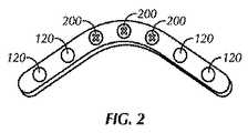
概して、図1に示されるように、本発明の実施形態は、組織インプラント100を対象とする。いくつかの実施形態では、組織インプラント100は、本体110と、1つ以上の開口120とを含む。一実施形態では、支柱140は、開口120を囲むかまたはそれに直接当接する。In general, as shown in FIG. 1, embodiments of the present invention are directed to a
図1−7に例証されるように、インプラント100は、図4に例証されるプレートの厚さ等、厚さ400を含み得る。インプラント100は、線形に構成されたプレート(例えば、図3に例証されるように)または角構成におけるプレート(例えば、図1およびに例証されるように2)を含み得る。しかしながら、インプラント100は、プレートに限定されず、任意の他の組織インプラントを含み得る。インプラント100はさらに、1つ以上の締結具200を含み得る。締結具200は、ネジ山付き締結具(例えば、ネジ、カニューレ付きネジ)、および非ネジ山付き締結具(例えば、ワイヤ、K−ワイヤ、カニューレ)を含み得る。As illustrated in FIGS. 1-7, the
一実施形態では、インプラント100は、締結具ブランク130を含む。締結具ブランク130は、ネジブランク(例えば、隠しネジ)またはボルトブランク(例えば、隠しボルト)を含み得る。一実施形態では、ネジブランクまたはボルトブランクは、具体的用途のために螺着することができるヘッドを伴うネジまたはボルトである。一実施形態では、締結具ブランク130は、シャンクを伴わないヘッドを備えている。一実施形態では、締結具ブランク130は、その長さ全体を通して均一直径を有する。そのような用途の1つでは、ネジヘッドまたはボルトヘッドは、開口120内のネジ山に整合するように螺着される。一実施形態では、締結具ブランク130は、開口120内にスナップ嵌めするように構成されるヘッドを含む。別の実施形態では、締結具ブランク130は、開口120内にプレス嵌めするように構成されるヘッドを含む。一実施形態では、締結具ブランク130は、本体110に固着して係止するように構成される。In one embodiment, the
一実施形態では、締結具ブランク130(例えば、隠しネジ)は、プレート等のインプラントの屈曲(例えば、予屈曲)中、係止ネジ山を保護するために使用される。屈曲動作の後、締結具ブランク130は、除去され、後に、ネジ、ボルト、またはネジ山付きワイヤ等の締結具と置換され得る。他の実施形態では、締結具ブランク130は、本明細書に説明されるように、移植されるように屈曲後、定位置に残され得る。そのような実施形態の1つでは、支柱140の分解速度は、移植された締結具ブランクが移植されたインプラント100内に含まれる場合、低減されるか、または実質的になくなる。一実施形態では、締結具ブランク130がインプラント100の開口内に埋め込まれると、インプラント100の上面または底面のいずれかからの分解は、より遅延される。一実施形態では、インプラント100の分解は、インプラント100の外面150からのみ生じる。In one embodiment, fastener blank 130 (eg, a hidden screw) is used to protect the locking threads during bending (eg, pre-bending) of animplant such as a plate. After the bending operation, the fastener blank 130 can be removed and later replaced with a fastener, such as a screw, bolt, or threaded wire. In other embodiments, the fastener blank 130 can be left in place after bending to be implanted, as described herein. In one such embodiment, the rate of disassembly of the
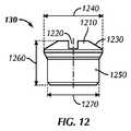
締結具ブランク130の一実施例は、図12および13に例証される。一実施形態では、締結具ブランク130は、所定の高さ1260、実質的に、椀形のヘッド1210と、本体1250とを有する。一実施形態では、ヘッド1210は、回転式締結ツールまたはドライバビット(図示せず)の遠位係合部分と係合するように、その上に形成された十字形の溝1220を有する。別の実施形態では、ヘッド1210は、所定の幅1240を有する。一実施形態では、ヘッド1210は、先細側部周辺部分1230を有する。 One example of a
図12および13に例証されるような締結具ブランク130はまた、ヘッド1210から下方に延在する本体1250を含む。一実施形態では、本体は、所定の幅1270を有する。一実施形態では、先細部分1230は、線形に先細になる。一実施形態では(図示せず)、締結具ブランク130の幅1240は、実質的に、締結具ブランク130の幅1270に等しい。締結具ブランク130は、高さ1260の全部または一部にわたってネジ山をつけられ得る。 Fastener blank 130 as illustrated in FIGS. 12 and 13 also includes a
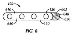
締結具ブランク130は、開口120内の所定の長さに延在するような構成および寸法を有し得る。一実施形態では、締結具ブランク130は、実質的に、開口120を充填するように構成される。一実施形態では、締結具ブランク130は、実質的にまたは完全に、開口120を充填するが、本体110またはインプラント100から突出しない。例えば、図4に例証されるように、締結具ブランク130は、インプラント100の第1の面430および第2の面440と同じ境界内にある、第1の端部410および第2の端部420を有する。一実施形態では、締結具ブランク130は、実質的に、厚さ400と均等の長さを有する。Fastener blank 130 may have a configuration and dimensions that extend a predetermined length within
図4に例証される一実施形態では、インプラント100は、1つ以上の締結具200によって、組織480(例えば、骨)に固着される。一実施形態では、締結具は、本体120の複数の開口のうちの少なくとも1つ内に配置され、組織480に固着される。一実施形態では、締結具ブランク130は、少なくとも1つの開口120(例えば、締結具200を受け取っていない開口120のうちの1つ)内に配置される。図1に例証されるように、2つ以上の締結具ブランク130が、インプラント100内に配置される。図4に例証されるように、インプラント100は、4つの締結具200および1つの締結具ブランク130を含む。一実施形態では、締結具ブランク130は、組織480内の裂け目470と整列するように構成される。本明細書に説明される、有益な効果を達成するために、締結具ブランク130は、生体力学的状況が許容するプレートの任意の他の位置に適用することができる。In one embodiment illustrated in FIG. 4,
いくつかの実施形態では、インプラント100は、分解性である材料(例えば、分解性金属またはポリマー)を備えている。本発明において有用である分解性金属は、マグネシウム、および分解性鉄、ならびにそれらの合金を含む。一実施形態では、インプラント100は、少なくとも2つの異なる材料を備えている(例えば、異なる電極電位または電気化学電位を有する、2つの異なる金属。マグネシウムは、例えば、標準電極電位−2.37Vを有し、鉄は、標準電極電位−0.44Vを有する。)。例えば、一実施形態では、本体110は、第1のノービリティ(nobility)を有する材料を備えているか、または実質的にそれから成り、締結具ブランク130は、第1の材料と異なるノービリティを有する第2の材料を備えているか、または実質的にそれから成る。一実施形態では、第1の材料は、第2の材料より貴(noble)である。別の実施形態では、第2の材料は、第1の実施形態より貴である。一実施形態では、第2の材料は、第1の材料の合金である。さらなる実施形態では、第2の材料は、第1の材料の合金ではない。In some embodiments, the
したがって、例えば、インプラント100は、本質的にマグネシウムから成る本体110と、マグネシウム合金から成る締結具ブランク130とを有するプレートを含み得る。そのような合金は、イットリウムおよび/またWE43あるいはWE54等の合金を含有する希土類を含み得る。一実施形態では、インプラント100は、両方合金である2つの金属を備えている。Thus, for example,
代替として、インプラント100は、本質的に、マグネシウム、鉄、またはそれらの合金から成る本体110と、本質的に、金または銀等のより貴な金属から成る締結具ブランクとを有するプレートを含み得る。一実施形態では、より貴な金属の存在は、本体110の分解をより貴な材料を伴わない場合より速く分解させる。Alternatively, the
したがって、本発明の実施形態は、いくつかの利点を提供し得る。例えば、一実施形態では、インプラント100は、インプラントの選択された材料および設計された特徴に基づいて制御される分解特性を伴って移植され得る。例えば、骨折を整復する目的のために移植される従来技術のマグネシウムインプラント100は、骨プレートである。プレートは、プレートを骨に固定する骨ネジを収容する開口120を含み得る。本発明に先立って、プレート開口120は、骨折に近接して、開放されたままであり得た。本事例では、プレート分解は、プレート開口120の両側から生じ、プレートの内部から加速され得る。本発明の一実施形態では、そうでなければ開放される開口120内に固定される締結具ブランクは、そのような分解を遅延させるか、または実質的に止める。代替として、本体110を構成する材料より分解性である材料を備えている締結具ブランクが移植され得る。そのような場合、より分解性の締結具ブランクが本体110の分解をさらに遅延させるために、犠牲的に分解され得る。Thus, embodiments of the present invention may provide several advantages. For example, in one embodiment,the
本明細書に開示される分解の制御は、締結具ブランクを有するインプラントに限定されない。例えば、一実施形態では、第1の材料部分610および第2の材料部分620を備えている本体110を有する組織インプラント100が存在する(例えば、図6および7に例証されるように)。The disassembly control disclosed herein is not limited toimplants having fastener blanks. For example, in one embodiment, there is a
一実施形態では、第1の材料部分610は、本質的に第1の材料を備えているか、またはそれから成り得、第2の材料部分620は、本質的に第2の材料を備えているか、または、それから成り得る。一実施形態では、そのような第1の材料は、体液に暴露されると、第2の材料の分解速度と異なる速度において分解し得る。一実施形態では、第2の材料部分620は、第1の材料部分610に対して犠牲アノードとして構成され得る。一実施形態では、第2の材料部分620は、本質的に、第1の材料部分610より卑である金属合金を備えているか、または、それから成り得る。一実施形態では、犠牲アノードが、例えば、ガルバニック腐食によって分解された後、インプラント110の残りの部分が腐食/分解を開始し得る。一実施形態では、第2の材料部分620および第1の材料部分610は、鍍着または溶接によって、組み合わせられる。In one embodiment, the
図6に例証される一実施形態では、インプラント100(例えば、プレート)は、少なくとも実質的に、第1の材料610によって囲まれている複数の開口120と、実質的に、第2の材料を備えている延長部分605とを有する主要本体630を含む。一実施形態では、延長部分605は、本質的に第2の材料から成る。一実施形態では、延長部分605は、第1の材料を覆って鍍着される第2の材料を含む。したがって、例えば、延長部分605は、第2の材料部分620によって囲まれる第1の材料部分610を含み得る。一実施形態では、延長部分605は、主要本体630に溶接される。In one embodiment illustrated in FIG. 6, theimplant 100 (eg, a plate) includes at least substantially a plurality of
図7に例証される一実施形態では、インプラント700(例えば、プレート)は、少なくとも実質的に、第1の材料610によって囲まれる複数の開口120を有する主要本体730を含む。インプラント700はまた、本質的に第2の材料を備えているか、または実質的に、それから成る区分705を含み得る。一実施形態では、主要本体730は、第1の材料を備えているか、または実質的に、それから成る。一実施形態では、第2の材料は、区分705において主要本体を覆って鍍着される。In one embodiment illustrated in FIG. 7,implant 700 (eg, a plate) includes a
図6および7に例証されるように、いくつかの実施形態では、インプラント100、700は、第1の材料610と第2の材料620との間に境界640、740を含む。一実施形態では、境界640は、インプラント100、700の片側から、インプラント100、700の反対側に延在する。一実施形態では、境界640は、湾曲境界を備えている。一実施形態では、境界640、740は、図7に例証されるように、扇形特徴を形成する。本発明の一実施形態では、インプラント100、700の大部分(または、本体110の大部分)は、第1の材料を備え、インプラント100、700の小部分は、第2の材料を備え、第1および第2の材料は、異なる分解特性(例えば、ノービリティ)を有する。一実施形態では、第2の材料は、第1の材料に対して、離散区分を含む。As illustrated in FIGS. 6 and 7, in some embodiments, the
一実施形態では、インプラント700は、第1の材料を覆って、あるパターンで鍍着される第2の材料を含む。一実施形態では、第2の材料は、第1の材料より電気化学的に貴である。そのような実施形態では、第2の材料の留置は、インプラントの分解を加速させ得る。一実施形態では、例えば、銀が分解性鉄インプラントの上部に鍍着され、鉄インプラントの分解を加速させ得る。例えば、図7のパターンは、多葉性境界を反映する。図9のパターンは、第2の材料620の離散線形区分を反映する。図10に例証される例示的パターンは、ドット620、菱形930、十字形940、およびロゴ950の形態において、第2の材料620の離散区分を反映する。他の規則的または不規則幾何学形状および線の離散区分もまた、生成され得る。In one embodiment, the
図11に例証される一実施形態では、第2の材料620は、情報960を移植を行っている外科医に提供するように構成され得る。情報は、例えば、インプラント100の意図された留置および/または配向に関する情報960を提供し得る。一実施形態では、情報960は、インプラント100の平均を成す材料より貴または卑な材料を含む。In one embodiment illustrated in FIG. 11, the
図8は、本発明のインプラント800の例示的断面図を例証する。一実施形態では、インプラント800は、カニューレ付き締結具である。インプラント800は、ヘッド810と、シャフト820(螺着され得、またはそうでなくてもよい)と、ヘッド810およびシャフト820を通して延在するカニューレ830とを有する主要本体880を含み得る。インプラント800はまた、カニューレ820と連続的であり得るソケット840を含み得る。FIG. 8 illustrates an exemplary cross-sectional view of an
一実施形態では、インプラント800はまた、カニューレ830内に嵌入するように構成され得る、挿入物850を含む。一実施形態では、挿入物850は、カニューレ830に密に嵌まる。一実施形態では、挿入物850は、シャフト860を含み、キャップ870を含み得る。一実施形態では、キャップ870は、シャフト860と連続的である。In one embodiment, the
インプラント800の一端から延在し、ソケット840を全体的に充填しない、キャップ870を例証するが、他の構成も、本発明の範囲内である。いくつかの実施形態では、例えば、挿入物850は、実質的に、カニューレ830および/またはソケット840を充填するように構成される。一実施形態では、挿入物850は、カニューレ830内に密に嵌入するワイヤ挿入物である。いくつかの実施形態では、キャップ870は、主要本体880と挿入物850との間の接触を改善するように、「たたき込まれる」。A
一実施形態では、本発明は、インプラントの分解を制御する方法を含む。一実施形態では、方法は、少なくとも1つの開口を有するインプラント(例えば、プレートまたはカニューレ付きネジを含む場合があるインプラント)を提供することを含む。一実施形態では、本方法のインプラントは、本質的に第1の材料から成る本体を有する。方法はさらに、インプラントを組織に固着することを含む。一実施形態では、方法は、開口内に挿入物を位置付け、実質的に、開口を充填することであって、挿入物は、本質的に、第1の材料より卑である第2の材料から成る、ことを含む。
In one embodiment, the present invention includes a method for controlling the degradation of an implant. In one embodiment, the method includes providing an implant (eg, an implant that may include a plate or cannulated screw) having at least one opening. In one embodiment, the implant of the method has a body consisting essentially of a first material. The method further includes securing the implant to the tissue. In one embodiment, the method is to position the insert within the aperture and substantially fill the aperture, where the insert is essentially from a second materialthat is baser than the first material. Including.
一実施形態では、方法は、複数の開口と、少なくとも1つの締結具ブランクとを有する第1のインプラント(例えば、プレートを含む場合がある、インプラント)を提供することを含む。方法は、開口の全部ではないが、一部を通して、締結具を挿入し、プレートを骨に固着することを含む場合がある。プレートを骨に固着後、方法はさらには、少なくとも1つの締結具ブランクを、挿入される締結具を含んでいない複数の開口のうちの少なくとも1つ内に挿入させることを含む場合がある。In one embodiment, the method includes a plurality of openings, a firstimplant having at least one fastener blank (e.g., which may include a plate,implant) to be provided. The method may include inserting a fastener through some but not all of the openings and securing the plate to the bone. After securing the plate to the bone, the method may further include inserting at least one fastener blank into at least one of the plurality of openings that do not include the fastener to be inserted.
したがって、本発明の実施形態は、いくつかの利点を提供し得る。例えば、一実施形態では、インプラント100は、インプラントの選択された材料および設計された特徴に基づいて制御される分解プロファイルを伴うインプラントであり得る。したがって、例えば、骨折の整復のために移植される、従来技術のマグネシウムインプラント100は、骨プレートである。プレートは、プレートを骨に固定する骨ネジを収容する開口120を含み得る。本発明に先立って、プレート開口120は、骨折に近接して開放されたままであり得た。本事例では、プレート分解は、体液が、インプラント100の内面(例えば、開口120を画定する面)に接触するのに伴って、プレートの内部からプレートの外部へと加速されるであろう。本発明の一実施形態では、別の開放開口120内に固定される締結具ブランク130は、本分解を遅延または実質的に減速させ得る。代替として、本体110を構成する材料より分解性である材料から成る、締結具ブランク130は、本体110の分解をさらに遅延させるために、犠牲的に分解され得る。Thus, embodiments of the present invention may provide several advantages. For example, in one embodiment, the
その広範な発明概念から逸脱することなく、前示および前述の例示的実施形態に変更が行われ得ることは、当業者によって理解されるであろう。したがって、本発明は、図示および説明される例示的実施形態に限定されず、請求項によって定義されるように、本発明の精神および範囲内の修正を網羅するように意図されることを理解されたい。例えば、例示的実施形態の具体的特徴は、請求される発明の一部であり得、またはそうでなくてもよく、開示される実施形態の特徴は、組み合わせられ得る。 It will be appreciated by those skilled in the art that changes may be made to the foregoing and previously described exemplary embodiments without departing from the broad inventive concept. Accordingly, it is to be understood that the invention is not limited to the illustrated and illustrated exemplary embodiments, but is intended to cover modifications within the spirit and scope of the invention as defined by the claims. I want. For example, specific features of the exemplary embodiments may or may not be part of the claimed invention, and features of the disclosed embodiments can be combined.
本発明の図および説明のうちの少なくともいくつかは、明確性の目的のために、同様に、本発明の一部を構成し得る、当業者が理解するであろう他の要素を排除しながら、本発明の明確な理解のために、関連する要素に焦点を当てるように簡略化されていることを理解されたい。しかしながら、そのような要素は、当技術分野において周知であって、必ずしも、本発明のさらなる理解を促進しないため、そのような要素の説明は、本明細書に提供されない。 At least some of the drawings and descriptions of the present invention, for the sake of clarity, likewise exclude other elements that would be understood by those skilled in the art that may form part of the present invention. It should be understood that, for a clear understanding of the present invention, it has been simplified to focus on relevant elements. However, a description of such elements is not provided herein because such elements are well known in the art and do not necessarily facilitate further understanding of the invention.
さらに、方法が、本明細書に記載されるステップの特定の順序に依存しない限り、ステップの特定の順序は、請求項に関する限定として解釈されるべきではない。本発明の方法を対象とする請求項は、書かれた順序でそのステップを行うことに限定されるべきではなく、当業者は、ステップが、変動され得、依然として、本発明の精神および範囲内にあることを容易に理解することができる。 Moreover, unless the method relies on a particular order of steps described herein, the particular order of steps should not be construed as a limitation on the claims. A claim directed to a method of the present invention should not be limited to performing the steps in the order written, and those skilled in the art can vary the steps and still remain within the spirit and scope of the present invention. Can be easily understood.
Claims (13)
Translated fromJapanese第1の金属材料を備えている本体であって、前記本体は、複数の開口を有している、本体と、
前記複数の開口のうちの少なくとも1つの中に配置されるように構成されている締結具であって、前記締結具は前記本体を組織に固着することができる、締結具と、
少なくとも1つの開口内に配置され、前記本体から実質的に突出することなく前記開口を実質的に充填するように構成されている締結具ブランクと
を備え、
前記締結具ブランクは、前記第1の金属材料より卑である第2の金属材料を含む、インプラントシステム。An implant system secured to tissue, the implant system comprising:
A main body comprising a first metal material, the main body having a plurality of openings;
A fastener configured to be disposed in at least one of the plurality of openings, the fastener capable of securing the body to tissue; and
A fastener blank disposed in at least one opening and configured to substantially fill the opening without substantially protruding from the body;
The implantsystem , wherein the fastener blank includes a second metal material thatis baser than the first metal material.
第1の金属材料を備えている本体であって、前記本体は、複数の開口を有している、本体と、
前記複数の開口のうちの少なくとも1つの中に配置されるように構成されている締結具であって、前記締結具は前記本体を組織に固着することができる、締結具と、
少なくとも1つの開口内に配置され、前記本体から実質的に突出することなく前記開口を実質的に充填するように構成されている締結具ブランクと
を備え、
前記締結具ブランクは、前記第1の金属材料の金属より貴である第2の金属材料を含む、インプラントシステム。An implant system secured to tissue, the implant system comprising:
A main body comprising a first metal material, the main body having a plurality of openings;
A fastener configured to be disposed in at least one of the plurality of openings, the fastener capable of securing the body to tissue; and
A fastener blank disposed in at least one opening and configured to substantially fill the opening without substantially protruding from the body;
The implant system, wherein the fastener blank includes a second metal material that is noble than the metal of the first metal material.
前記本体は、第1の金属材料および第2の金属材料と、前記第1の金属材料および前記第2の金属材料の間の湾曲した境界とを備え、前記第1の金属材料は、前記第2の金属材料より貴である、組織インプラント。Aplate comprising a body configured to be implanted in tissue;
The main body includes a first metal material and a second metal material, and a curved boundary between the first metal material and the second metal material, wherein the first metal material is the first metal material. A tissue implant that is noble than two metal materials.
前記本体は、
第1の金属材料を備えているカニューレと、
前記第2の金属材料を備えているワイヤ挿入物であって、前記ワイヤ挿入物は、前記カニューレ内に密に嵌入するように構成されている、ワイヤ挿入物と
を備え、
前記第1の金属材料は、前記第2の金属材料より貴である、組織インプラント。A tissue implant comprising a body configured to be implanted within tissue;
The body is
A cannula comprising a first metallic material;
A wire insert comprising the second metallic material, wherein the wire insert is configured to fit tightly within the cannula;
The tissue implant wherein the first metallic material is noble than the second metallic material.
前記本体の大部分は、本質的に第1の金属材料から成り、
前記本体の小部分は、本質的に第2の金属材料から成り、
前記第2の金属材料は、電気化学的に前記第1の金属材料より貴であり、
前記第2の金属材料は前記第1の金属材料上にあるパターンで鍍着される、
組織インプラント。A tissue implant comprising a body configured to be implanted within tissue;
The majority of the body consists essentially of the first metallic material,
A small portion of the body consists essentially of a second metallic material,
Thesecond metallic material, TakashideaRi fromelectrochemically saidfirst metallic material,
The second metal material is deposited in a pattern on the first metal material;
Tissue implant.
少なくとも1つの開口を有するインプラントであって、前記インプラントは、本質的に第1の金属材料から成る本体を有し、前記インプラントが組織に固着されるように構成されている、インプラントと、
前記開口内に位置付けられ、前記開口を実質的に充填するように構成された挿入物と
を備え、
前記挿入物は、本質的に、前記第1の金属材料より卑である第2の金属材料から成る、システム。A system for controlling the degradation of a tissue implant, the system comprising:
An implant having at least one opening, the implant having a body consisting essentially of a first metallic material, the implant configured to be secured to tissue;
An insert positioned within the opening and configured to substantially fill the opening;
The system, wherein the insert consists essentiallyof a second metallic materialthat is baser than the first metallic material.
Applications Claiming Priority (3)
| Application Number | Priority Date | Filing Date | Title |
|---|---|---|---|
| US37874710P | 2010-08-31 | 2010-08-31 | |
| US61/378,747 | 2010-08-31 | ||
| PCT/US2011/048362WO2012030552A1 (en) | 2010-08-31 | 2011-08-19 | Controlling the degradation of bioresorbable metal implants |
Publications (3)
| Publication Number | Publication Date |
|---|---|
| JP2013536704A JP2013536704A (en) | 2013-09-26 |
| JP2013536704A5 JP2013536704A5 (en) | 2016-06-02 |
| JP5976647B2true JP5976647B2 (en) | 2016-08-24 |
Family
ID=44588191
Family Applications (1)
| Application Number | Title | Priority Date | Filing Date |
|---|---|---|---|
| JP2013526035AActiveJP5976647B2 (en) | 2010-08-31 | 2011-08-19 | Degradation control of bioabsorbable metal implants |
Country Status (9)
| Country | Link |
|---|---|
| US (2) | US10039580B2 (en) |
| EP (1) | EP2611377B1 (en) |
| JP (1) | JP5976647B2 (en) |
| KR (1) | KR101856459B1 (en) |
| CN (1) | CN103079485B (en) |
| BR (1) | BR112013000997B1 (en) |
| CA (2) | CA2806599C (en) |
| TW (1) | TWI577323B (en) |
| WO (1) | WO2012030552A1 (en) |
Families Citing this family (5)
| Publication number | Priority date | Publication date | Assignee | Title |
|---|---|---|---|---|
| JP6177789B2 (en)* | 2011-11-07 | 2017-08-09 | シンセス・ゲーエムベーハーSynthes GmbH | Dilute electrolyte for biocompatible plasma electrolytic coating of magnesium implant materials |
| DE102012006454A1 (en)* | 2012-03-30 | 2013-10-02 | Heraeus Medical Gmbh | Anti-infective spacer for osteosynthesis plates |
| BR112022016152A2 (en)* | 2020-02-14 | 2022-10-04 | Paragon 28 Inc | BONE PLATE HOLE COVERS, BONE PLATE SYSTEMS AND METHODS USING THE SAME . |
| CN114098936B (en)* | 2021-11-30 | 2022-09-20 | 吉林大学 | Degradable bionic double-layer humerus bone fracture plate |
| DE102022106581A1 (en)* | 2022-03-21 | 2023-09-21 | Medical Magnesium GmbH | Osteosynthesis system with bone plate and bone anchor made of magnesium alloys |
Family Cites Families (32)
| Publication number | Priority date | Publication date | Assignee | Title |
|---|---|---|---|---|
| CH652911A5 (en)* | 1982-01-29 | 1985-12-13 | Sulzer Ag | STRAIGHT, LEAF-LIKE SHAFT FOR A JOINT OPROTHESIS. |
| DE59503119D1 (en) | 1994-04-22 | 1998-09-17 | Straumann Inst Ag | Screwing tool for a screw, consisting of a bolt part and a nut that can be screwed onto it |
| FR2748387B1 (en) | 1996-05-13 | 1998-10-30 | Stryker France Sa | BONE FIXATION DEVICE, IN PARTICULAR TO THE SACRUM, IN OSTEOSYNTHESIS OF THE SPINE |
| ES2297092T3 (en)* | 1997-02-11 | 2008-05-01 | Warsaw Orthopedic, Inc. | PREVIOUS CERVICAL PLATE OF UNIQUE BLOCK. |
| SE524615C2 (en)* | 1999-06-30 | 2004-09-07 | Volvo Personvagnar Ab | Arrangements for reducing galvanic corrosion between metal components |
| US6926719B2 (en) | 1999-10-21 | 2005-08-09 | Gary W. Sohngen | Modular intramedullary nail |
| US6767351B2 (en) | 2000-02-01 | 2004-07-27 | Hand Innovations, Inc. | Fixation system with multidirectional stabilization pegs |
| US6808527B2 (en) | 2000-04-10 | 2004-10-26 | Depuy Orthopaedics, Inc. | Intramedullary nail with snap-in window insert |
| US6605090B1 (en) | 2000-10-25 | 2003-08-12 | Sdgi Holdings, Inc. | Non-metallic implant devices and intra-operative methods for assembly and fixation |
| US6656181B2 (en) | 2000-11-22 | 2003-12-02 | Robert A Dixon | Method and device utilizing tapered screw shanks for spinal stabilization |
| US7104991B2 (en)* | 2001-02-27 | 2006-09-12 | Robert A Dixon | Method and device for using extended interference fit screw shanks for spinal stabilization |
| US20070173840A1 (en) | 2006-01-11 | 2007-07-26 | Huebner Randall J | Bone plate with cover |
| ITTO20011059A1 (en)* | 2001-11-09 | 2003-05-09 | Biotek S R L | VARIABLE FLEXIBILITY PLATE FOR OSTEOSYNTHESIS. |
| US7207994B2 (en) | 2002-02-12 | 2007-04-24 | Pioneer Laboratories, Inc. | Cannulated bone screw |
| ES2306800T3 (en)* | 2002-12-17 | 2008-11-16 | Synthes Gmbh | INTERVERTEBRAL IMPLANT. |
| US7306605B2 (en)* | 2003-10-02 | 2007-12-11 | Zimmer Spine, Inc. | Anterior cervical plate |
| EP1693013A1 (en)* | 2005-02-22 | 2006-08-23 | Kyon | Plate and screws for treatment of bone fractures |
| EP1865882A4 (en) | 2005-04-05 | 2013-05-08 | Elixir Medical Corp | Degradable implantable medical devices |
| US8840660B2 (en) | 2006-01-05 | 2014-09-23 | Boston Scientific Scimed, Inc. | Bioerodible endoprostheses and methods of making the same |
| US7875062B2 (en) | 2006-03-07 | 2011-01-25 | Warsaw Orthopedic, Inc. | Methods and devices for retaining bone plate anchors |
| US7867261B2 (en) | 2006-03-17 | 2011-01-11 | Depuy Products, Inc. | Bone plate with variable torsional stiffness at fixed angle holes |
| US20070225707A1 (en) | 2006-03-22 | 2007-09-27 | Sdgi Holdings, Inc. | Orthopedic spinal devices fabricated from two or more materials |
| US20070288016A1 (en) | 2006-06-05 | 2007-12-13 | Subhash Chandra Halder | Bone support |
| US7674279B2 (en)* | 2006-10-13 | 2010-03-09 | Spinal U.S.A. | Bone plate |
| EP2114263B1 (en) | 2007-02-28 | 2019-02-20 | Smith & Nephew, Inc. | System for identifying a landmark |
| CA2698057A1 (en) | 2007-08-30 | 2009-03-05 | P Tech, Llc | Methods and devices for utilizing thermal energy to bond, stake and/or remove implants |
| EP2397094B1 (en)* | 2007-11-02 | 2013-06-26 | Biomet C.V. | Elbow fracture fixation system |
| US20090198286A1 (en)* | 2008-02-05 | 2009-08-06 | Zimmer, Inc. | Bone fracture fixation system |
| US20090264924A1 (en) | 2008-04-19 | 2009-10-22 | James Ushiba | Surgical device and method |
| CN101283922A (en) | 2008-05-21 | 2008-10-15 | 中国科学院金属研究所 | Bioactive Absorbable Bone Internal Fixation Implant Device |
| CA2728826C (en) | 2008-06-26 | 2016-05-03 | Ao Technology Ag | Bone fixation device with cover |
| US20110087295A1 (en)* | 2009-10-12 | 2011-04-14 | University Of Utah | Bone fixation systems |
- 2011
- 2011-08-19JPJP2013526035Apatent/JP5976647B2/enactiveActive
- 2011-08-19USUS13/213,213patent/US10039580B2/enactiveActive
- 2011-08-19CACA2806599Apatent/CA2806599C/enactiveActive
- 2011-08-19EPEP11754954.3Apatent/EP2611377B1/enactiveActive
- 2011-08-19CNCN201180041517.XApatent/CN103079485B/enactiveActive
- 2011-08-19KRKR1020137003708Apatent/KR101856459B1/enactiveActive
- 2011-08-19WOPCT/US2011/048362patent/WO2012030552A1/enactiveApplication Filing
- 2011-08-19CACA3065709Apatent/CA3065709A1/ennot_activeAbandoned
- 2011-08-19BRBR112013000997-7Apatent/BR112013000997B1/enactiveIP Right Grant
- 2011-08-24TWTW100130274Apatent/TWI577323B/enactive
- 2018
- 2018-07-17USUS16/037,136patent/US10653463B2/ennot_activeExpired - Fee Related
Also Published As
| Publication number | Publication date |
|---|---|
| EP2611377B1 (en) | 2020-12-09 |
| TW201225899A (en) | 2012-07-01 |
| US20120053637A1 (en) | 2012-03-01 |
| BR112013000997B1 (en) | 2021-05-04 |
| BR112013000997A2 (en) | 2016-05-24 |
| CA2806599A1 (en) | 2012-03-08 |
| TWI577323B (en) | 2017-04-11 |
| WO2012030552A9 (en) | 2012-08-02 |
| CN103079485A (en) | 2013-05-01 |
| CA3065709A1 (en) | 2012-03-08 |
| EP2611377A1 (en) | 2013-07-10 |
| KR101856459B1 (en) | 2018-05-10 |
| US20180317983A1 (en) | 2018-11-08 |
| US10039580B2 (en) | 2018-08-07 |
| CN103079485B (en) | 2016-05-11 |
| US10653463B2 (en) | 2020-05-19 |
| WO2012030552A1 (en) | 2012-03-08 |
| JP2013536704A (en) | 2013-09-26 |
| KR20130094797A (en) | 2013-08-26 |
| CA2806599C (en) | 2020-03-10 |
Similar Documents
| Publication | Publication Date | Title |
|---|---|---|
| US10653463B2 (en) | Controlling the degradation of bioresorbable metal implants | |
| US9522019B2 (en) | Implant for bones or vertebrae with self-constrained flexibility | |
| US8623060B2 (en) | Cannulated bone screw | |
| US8323321B2 (en) | Implant and bone screw having interlocking cams | |
| US20040044345A1 (en) | Shallow penetration bone screw | |
| EP1331283A4 (en) | Tantalum or tungsten target-copper alloy backing plate assembly and production method therefor | |
| CN100575721C (en) | Bolt with extruded thread and its production method | |
| ES2406375T3 (en) | Hollow fixing element for the electrically conductive application of an electrical connection installation to a sheet metal part, as well as a mounting component with this fixing element | |
| WO2007109140A2 (en) | Bone screw with selectively securable washer | |
| US20070093836A1 (en) | Osteosynthesis device | |
| WO2005087982A8 (en) | Metal implants | |
| TW200643207A (en) | Deep-pot-shaped copper sputtering target and process for producing the same | |
| WO2009132445A1 (en) | Anchor for use with orthopedic screw | |
| JP2013536704A5 (en) | ||
| WO2009134320A2 (en) | Anchor apparatus for orthodontic appliances | |
| US11540898B2 (en) | Bone screw with frangible tracking tag | |
| MY136536A (en) | Anode for oxygen evolution and relevant substrate | |
| JP2010057743A (en) | Screw for bone part | |
| JP2009207710A (en) | Implant for treating fracture of femur | |
| WO2014097310A1 (en) | A medical equipment for anchoring and closing of cranial flap during neurosurgery of head | |
| JP2009008112A (en) | Screw and screwdriver | |
| JP2007244676A (en) | Abutment | |
| US20250152785A1 (en) | Osteosynthesis system with bone plate and bone anchor made of magnesium alloys | |
| JP2007215912A (en) | Instrument for operation | |
| JP2013094628A (en) | External fixation pin |
Legal Events
| Date | Code | Title | Description |
|---|---|---|---|
| A521 | Request for written amendment filed | Free format text:JAPANESE INTERMEDIATE CODE: A523 Effective date:20130301 | |
| A521 | Request for written amendment filed | Free format text:JAPANESE INTERMEDIATE CODE: A821 Effective date:20130828 | |
| RD02 | Notification of acceptance of power of attorney | Free format text:JAPANESE INTERMEDIATE CODE: A7422 Effective date:20130828 | |
| RD04 | Notification of resignation of power of attorney | Free format text:JAPANESE INTERMEDIATE CODE: A7424 Effective date:20130906 | |
| A621 | Written request for application examination | Free format text:JAPANESE INTERMEDIATE CODE: A621 Effective date:20140811 | |
| A977 | Report on retrieval | Free format text:JAPANESE INTERMEDIATE CODE: A971007 Effective date:20150410 | |
| A131 | Notification of reasons for refusal | Free format text:JAPANESE INTERMEDIATE CODE: A131 Effective date:20150421 | |
| A521 | Request for written amendment filed | Free format text:JAPANESE INTERMEDIATE CODE: A523 Effective date:20150721 | |
| A524 | Written submission of copy of amendment under article 19 pct | Free format text:JAPANESE INTERMEDIATE CODE: A524 Effective date:20150721 | |
| A131 | Notification of reasons for refusal | Free format text:JAPANESE INTERMEDIATE CODE: A131 Effective date:20151208 | |
| A601 | Written request for extension of time | Free format text:JAPANESE INTERMEDIATE CODE: A601 Effective date:20160308 | |
| A521 | Request for written amendment filed | Free format text:JAPANESE INTERMEDIATE CODE: A523 Effective date:20160407 | |
| A524 | Written submission of copy of amendment under article 19 pct | Free format text:JAPANESE INTERMEDIATE CODE: A524 Effective date:20160407 | |
| TRDD | Decision of grant or rejection written | ||
| A01 | Written decision to grant a patent or to grant a registration (utility model) | Free format text:JAPANESE INTERMEDIATE CODE: A01 Effective date:20160712 | |
| A61 | First payment of annual fees (during grant procedure) | Free format text:JAPANESE INTERMEDIATE CODE: A61 Effective date:20160720 | |
| R150 | Certificate of patent or registration of utility model | Ref document number:5976647 Country of ref document:JP Free format text:JAPANESE INTERMEDIATE CODE: R150 | |
| R250 | Receipt of annual fees | Free format text:JAPANESE INTERMEDIATE CODE: R250 | |
| R250 | Receipt of annual fees | Free format text:JAPANESE INTERMEDIATE CODE: R250 | |
| R250 | Receipt of annual fees | Free format text:JAPANESE INTERMEDIATE CODE: R250 | |
| R250 | Receipt of annual fees | Free format text:JAPANESE INTERMEDIATE CODE: R250 | |
| R250 | Receipt of annual fees | Free format text:JAPANESE INTERMEDIATE CODE: R250 |