JP5975609B2 - Cart equipment - Google Patents
Cart equipmentDownload PDFInfo
- Publication number
- JP5975609B2 JP5975609B2JP2011154285AJP2011154285AJP5975609B2JP 5975609 B2JP5975609 B2JP 5975609B2JP 2011154285 AJP2011154285 AJP 2011154285AJP 2011154285 AJP2011154285 AJP 2011154285AJP 5975609 B2JP5975609 B2JP 5975609B2
- Authority
- JP
- Japan
- Prior art keywords
- electronic device
- article
- support
- cart
- top plate
- Prior art date
- Legal status (The legal status is an assumption and is not a legal conclusion. Google has not performed a legal analysis and makes no representation as to the accuracy of the status listed.)
- Active
Links
Images


Landscapes
- Accommodation For Nursing Or Treatment Tables (AREA)
- Tables And Desks Characterized By Structural Shape (AREA)
- Handcart (AREA)
Description
Translated fromJapanese本発明は、カート装置に関するものである。 The present invention relates to a cart apparatus.
従来、オフィス、病院、公共施設等における執務空間においては、執務空間内の様々な場所に移動しながら電子機器を用いて執務を行う場合がある。この場合、カート装置の天板上に電子機器を載置し、執務者がカート装置と共に移動し、随時必要に応じた場所にて執務が行われていた。 Conventionally, in office spaces such as offices, hospitals, and public facilities, there are cases where offices are used to move to various locations within the office space using electronic devices. In this case, an electronic device is placed on the top plate of the cart apparatus, and the worker moves with the cart apparatus, and the office work is performed at a place as necessary.
カート装置としては、下部に設けられた床面上を走行可能な移動手段又はローラ等と、下部から上方に立設された脚体と、該脚体に設けられた作業用のテーブル板又はデスク(天板と称する。以下同じ。)とを搭載した簡易な構成のものが多く知られている。(下記特許文献1、2参照)。 The cart device includes a moving means or a roller or the like that can run on the floor surface provided at the lower part, a leg member that is erected upward from the lower part, and a work table plate or desk provided on the leg member. There are many well-known ones equipped with (referred to as a top plate; the same applies hereinafter). (See Patent Documents 1 and 2 below).
しかしながら、前述のカート装置では、執務に必要な物品を載置できるのは天板の上面のみであり、他の部分は物品を載置する機能を備えていないため、物品の収納能力が低いという問題点があった。さらに、天板を筆記等の作業台として使用する際には、カート装置全体で物品を全く載置することができないため、収容能力が著しく低くなるという問題点があった。さらには、多数の物品を載置した状態でカート装置を移動させながら執務を行うことができないため、使い勝手が悪く、作業効率が劣るという問題点もあった。 However, in the cart apparatus described above, the articles necessary for work can be placed only on the top surface of the top plate, and the other parts do not have a function for placing articles, so the article storage capacity is low. There was a problem. Furthermore, when the top board is used as a work table for writing or the like, there is a problem in that the storage capacity is remarkably lowered because articles cannot be placed at all in the cart apparatus as a whole. Furthermore, since the work cannot be performed while moving the cart apparatus in a state where a large number of articles are placed, there is a problem that the usability is poor and the work efficiency is inferior.
本発明は、上記事情に鑑みてなされたものであり、物品を載置可能とし、執務者の使い勝手、執務効率を良好とするカート装置を提供するものである。 The present invention has been made in view of the above circumstances, and provides a cart apparatus that can place an article and that is easy to use for a worker and has good work efficiency.
上記目的を達成するために、本発明は以下の手段を採用している。
すなわち、本発明に係るカート装置は、床面上を走行可能とされたベース部と、該ベース部から立設された支持基体と、該支持基体の上端に設けられた天板と、該天板から後方に突設された操作ハンドル部と、前記ベース部と前記天板との間において、前記支持基体から前方に突出するように設けられた第一物品載置部と、前記ベース部と前記天板との間において、前記支持基体から後方に突出するように設けられた第二物品載置部とを備え、前記第一物品載置部は、前記支持基体を中心として左右両側方に延在するとともに、前記支持基体に対して左右両側方を通して前記支持基体よりも後方からアクセス可能とされ、前記第二物品載置部は、前記支持基体を中心として左右両側方に延在するとともに、前記支持基体に対して左右両側方を通して前記支持基体よりも前方からアクセス可能とされ、前記第一物品載置部及び前記第二物品載置部は、それぞれ前記支持基体に対する取り付け位置が上下方向に変更可能に構成されていることを特徴とする。In order to achieve the above object, the present invention employs the following means.
That is, the cart device according to the present invention includes a base portion that can run on a floor surface, a support base that is erected from the base portion, a top plate that is provided at the upper end of the support base, and the ceiling. An operation handle portion protruding rearward from the plate, a first article placement portion provided so as to protrude forward from the support base between the base portion and the top plate, and the base portion A second article placement section provided between the top board and the support base so as to protrude rearward from the support base, wherein the first article placement section is located on both left and right sides of the support base. The second article placement portion extends to both the left and right sides with the support base as a center, and extends from the rear of the support base through the left and right sides of the support base. The left and right sides of the support base Is from the front than the support base andaccessible, the first article placing section and the second article placing portion, the mounting position is configured to be changed in the vertical direction with respect to each of the supporting base It is characterized by.
この構成では、物品を第一物品載置部及び第二物品載置部に載置できるため、物品を載置しながらベース部によりカート装置を移動させることができる。よって、執務者は、移動しながら載置した物品を使用して執務を行うことができるため、執務者の使い勝手を良好とすることができる。
また、第一物品載置部及び第二物品載置部の両方に物品を載置することができ多くの物品を載置できるため、物品を運搬しながら執務する際における執務者の執務効率を良好とすることができる。In this configuration, since the article can be placed on the first article placement section and the second article placement section, the cart device can be moved by the base portion while placing the article. Therefore, since the office worker can perform the office work using the article placed while moving, the usability of the office worker can be improved.
Moreover, since articles can be placed on both the first article placement section and the second article placement section, and many articles can be placed, it is possible to improve the work efficiency of the workers when working while transporting articles. Can be good.
また、執務者は、カート装置の後方から、支持基体の前方に配された第一物品載置部にアクセスが可能であるため、第一物品載置部に載置された物品を取り出したり、又は第一物品載置部に物品を載置することができる。同様に、執務者は、カート装置の前方から、支持基体の後方に配された第二物品載置部にアクセスが可能であるため、第二物品載置部に載置された物品を取り出したり、又は第二物品載置部に物品を載置することができる。したがって、執務者の使い勝手を良好とすることができる。In addition, since the office worker can access the first article placement section arranged in front of the support base from the rear of the cart device, the worker can take out the article placed on the first article placement section, Alternatively, the article can be placed on the first article placement section. Similarly, the office worker can access the second article placement section disposed behind the support base from the front of the cart device, and therefore can take out the articles placed on the second article placement section. Alternatively, the article can be placed on the second article placement section. Therefore, the convenience of the office worker can be improved.
また、本発明に係るカート装置は、前記第一物品載置部は、略板状に形成され、前記第二物品載置部は、物品を載置する支持部と、該支持部から上方に立ち上がる側壁部とを備えることを特徴とする。 In the cart device according to the present invention, the first article placement section is formed in a substantially plate shape, and the second article placement section includes a support section for placing an article, and an upper side from the support section. And a side wall portion that rises.
この構成では、操作ハンドル部が天板の後方に突設して設けられているため、執務者は、カート装置の後方に立ち、操作ハンドル部を操作してカート装置を移動させる形態をとることができる。したがって、第二物品載置部に使用頻度の高い物品を載置すれば、第二物品載置部は執務者の位置から近いために、執務者の使い勝手を良好とすることができる。
また、第二物品載置部は物品を載置する支持部と、該支持部から上方に立ち上がる側壁部とを備える構成である。よって、執務者は執務をする際に、腰を屈めずに立ったままの姿勢で手探りで物品を取り出したとしても、該物品が側壁部に囲まれていることにより落下することはないため、執務者の使い勝手を良好とすることができる。
一方、第一物品載置部は、略板状に形成されているために多くの物品を載置することができ、カート装置を移動させれば運搬性が向上するため、執務効率を良好とすることができる。In this configuration, since the operation handle portion is provided protruding from the back of the top plate, the office worker takes a form of standing behind the cart device and operating the operation handle portion to move the cart device. Can do. Therefore, if an article with a high use frequency is placed on the second article placement section, the second article placement section is close to the position of the worker, and thus the convenience of the worker can be improved.
The second article placement section includes a support section for placing an article and a side wall section that rises upward from the support section. Therefore, when the office worker works, even if he takes out the article by groping in a posture while standing without bending, the article will not fall because it is surrounded by the side wall, It is possible to improve the convenience of office workers.
On the other hand, since the first article placement portion is formed in a substantially plate shape, many articles can be placed, and if the cart device is moved, the transportability is improved. can do.
また、本発明に係るカート装置は、前記第一物品載置部の上方に、前方、右方及び左方に開放された取出空間が形成されていることを特徴とする。 The cart device according to the present invention is characterized in that an extraction space opened forward, rightward and leftward is formed above the first article placement portion.
この構成では、執務者は、第一物品載置部に対して、前方、右方及び左方の三方向に開放された取出空間からアクセスすることができるため、第一物品載置部に載置された物品を三方向から容易に取り出すことができ、執務者の使い勝手を良好とすることができる。 In this configuration, the office worker can access the first article placement unit from the extraction space opened in the three directions of the front, right side, and left side. The placed article can be easily taken out from three directions, and the convenience of the office worker can be improved.
また、本発明に係るカート装置は、前記天板から上方に設けられるとともに、電子機器を着脱可能に支持する電子機器支持部と、該電子機器支持部に支持された前記電子機器とを備えることを特徴とする。 In addition, the cart device according to the present invention includes an electronic device support unit that is provided above the top plate and that removably supports the electronic device, and the electronic device that is supported by the electronic device support unit. It is characterized by.
この構成では、第一物品載置部及び第二物品載置部に物品を載置しながらカート装置を移動させることができるとともに、天板の上方に設けられた電子機器を使用して執務をすることができる。ここで、電子機器は天板の上方に設けられた電子機器支持部に支持されているため、電子機器を使用するともに、天板も有効活用することができる。さらに、電子機器支持部は電子機器を着脱可能に支持しているため、電子機器を使用しない場合には電子機器支持部から電子機器を取り外すことができる。したがって、執務者は、一のカート装置により、物品を運搬し、電子機器を使用し、及び天板上で作業することができるため、執務者の使い勝手を良好とすることができる。 In this configuration, the cart device can be moved while placing an article on the first article placement section and the second article placement section, and the electronic device provided above the top board is used for work. can do. Here, since the electronic device is supported by an electronic device support provided above the top plate, the electronic device can be used and the top plate can be effectively used. Furthermore, since the electronic device support unit detachably supports the electronic device, the electronic device can be detached from the electronic device support unit when the electronic device is not used. Therefore, the office worker can carry the articles, use the electronic apparatus, and work on the top board with one cart device, so that the office worker can improve the usability.
また、本発明に係るカート装置は、前記電子機器は、姿勢を変更可能として前記電子機器支持部に支持されていることを特徴とする。 The cart device according to the present invention is characterized in that the electronic device is supported by the electronic device support section so that the posture of the electronic device can be changed.
この構成では、執務者は、電子機器支持部の姿勢を変更することにより、電子機器の画面の角度を変更することができる。よって、例えば、執務者がカート装置の後方に位置し、電子機器の画面を後方に向けてカート装置を移動させている態様、執務者がカート装置の側方に位置し、電子機器の画面を右方又は左方に向けて執務する態様、又は執務者がカート装置の前方に位置し、電子機器の画面を前方に向けて天板上で作業する態様と、様々な態様をとることができる。したがって、執務者の使い勝手を良好とすることができる。 In this configuration, the office worker can change the angle of the screen of the electronic device by changing the posture of the electronic device support section. Thus, for example, the worker is located behind the cart device and the cart device is moved with the screen of the electronic device facing backward, the worker is located beside the cart device, and the screen of the electronic device is Various modes can be taken, such as a mode of working toward the right side or the left side, or a mode in which the worker is positioned in front of the cart device and works on the top board with the screen of the electronic device facing forward. . Therefore, the convenience of the office worker can be improved.
また、本発明に係るカート装置は、前記支持基体は、上下方向に伸縮可能であることを特徴とする。 The cart device according to the present invention is characterized in that the support base is extendable in the vertical direction.
この構成では、執務者の身長、執務時の姿勢に合わせて、支持基体を上下方向に伸縮させればカート装置の天板の高さを変更することができるため、執務者の使い勝手を良好とすることができる。 In this configuration, the height of the top plate of the cart device can be changed by extending and contracting the support base in the vertical direction according to the height of the worker and the posture at the time of work. can do.
本発明に係るカート装置によれば、物品を載置可能とし、執務者の使い勝手、執務効率を良好とすることができる。 According to the cart device of the present invention, it is possible to place an article, and it is possible to improve the usability and work efficiency of a worker.
以下、本発明の一実施形態について、図面を参照して説明する。
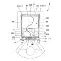
図1に示すように、本実施形態に係るカート装置1は、床面F上を走行可能とされたベース部11と、ベース部11から立設された支持基体21と、支持基体21の上端に設けられた天板31と、天板31に設けられた操作ハンドル部41と、天板31に設けられるとともに、電子機器Eを支持する電子機器支持部51と、電子機器支持部51に支持された電子機器Eと、支持基体21の前方に配された第一物品載置部61と、支持基体21の後方に配された第二物品載置部71とを備えている。
執務者は、電子機器支持部51に支持された電子機器Eを使用可能であるとともに、操作ハンドル部41を把持して操作力を与えることで床面F上でカート装置1を移動させることが可能となっている。
ここで、執務者が操作ハンドル部41と対向するように位置して操作ハンドル部41を押し引きする方向となる図1の紙面左右方向をカート装置1の前後方向とし、操作ハンドル部41を押す側となる紙面右側をカート装置1の「前側」、操作ハンドル部41を引く側となる紙面左側をカート装置1の「後側」と称する。また、平面視して前後方向と直交する方向となる図2の紙面左右方向をカート装置1の左右方向とし、紙面右側をカート装置1の「右側」、紙面左側をカート装置1の「左側」と称する。
以下、各構成の詳細を説明する。Hereinafter, an embodiment of the present invention will be described with reference to the drawings.
As shown in FIG. 1, the cart device 1 according to the present embodiment includes a
The office worker can use the electronic device E supported by the electronic
Here, the left-right direction in FIG. 1, which is the direction in which the office worker faces the
Details of each component will be described below.
図1及び2に示すように、ベース部11は、床面F上を走行可能な複数のキャスター111と、該キャスター111が設けられた脚杆112とを備える。
脚杆112は、支持基体21の下端より、前方及び後方であって、それぞれ左右方向に延びる4本の脚杆112により構成される。
キャスター111は、各脚杆112の先端部の下面に、床面Fに直交する垂直軸周りに旋回可能に設けられている。As shown in FIGS. 1 and 2, the
The
The
支持基体21は、ベース部11の前後方向略中央より後方から上下方向に立設されるとともに筒状の外側支柱121と、該外側支柱121の内部に挿入されている内側支柱122とを備える。
外側支柱121は、ベース部11の前後方向の略中央よりも後方よりであって、左右方向の略中央に設けられている。
また、外側支柱121の前部には、前方に張り出す第一支持部123が設けられ、外側支柱121の後部には、後方に張り出す第二支持部124が設けられている。ここで、第一支持部123、第二支持部124は、後述する第一物品載置部61、第二物品載置部71を支持している。
内側支柱122は、外側支柱121に対して上下方向に進退可能に設けられている。また、内側支柱122の内部には図示しないガススプリングが設けられており、天板31の下面に設けられた操作レバー131を操作することによりガススプリングの上下方向の高さを伸縮させる。これにより、内側支柱122は外側支柱121に対して相対的に上下方向に移動するとともに、天板31の高さを昇降させて調節可能としている。The
The
In addition, a
The
天板31は、上面が床面と平行な状態となるとともに略矩形状に形成され、支持基体21に支持されている。そして、上面は薬品等の物品が載置可能であり、又はカルテ等の記載が可能な作業台として使用することができる。 The
操作ハンドル部41は、天板31の後部であって、左右両側から後方に突設された一対のハンドル取付部141と、該ハンドル取付部141を連結する把持部142とを備える。 The
電子機器支持部51は、天板31の後部であって、左右方向の略中央に設けられた天板延設部151と、該天板延設部151の後部から上方に立設された支持軸152と、該支持軸152の上部に設けられた第一ヒンジ部153と、支持軸152の下部に設けられた第二ヒンジ部154と、電子機器Eを取り付ける電子機器取付部155とを備える。
天板延設部151は、支持軸152の下端から下方に延びて、当該下端から天板31の下面に沿って前方へ延設されている。また、天板延設部151は、図示しないネジ等により天板31に固定されている。
支持軸152は、天板延設部151の後部より上方に立設されるとともに、上部には電子機器取付部155が設けられている。また、支持軸152は、平面視して、天板31の後部よりも後方であって、操作ハンドル部41の把持部142よりも前方に位置している。
図3(a)に示すように、第一ヒンジ部153は、支持軸152の上部に設けられるとともに、左右方向に沿う軸Pを中心に電子機器Eを公知の支持構造によって回動可能としている。よって、左右方向に沿う軸Pを中心に電子機器Eを回動すると、電子機器Eの表面Tを上方に向ける位置Gとすることが可能である。
図3(a)、(b)に示すように、第二ヒンジ部154は、支持軸152の下部に設けられるとともに、左右方向に沿う軸R及び上下方向に沿う軸Qを中心に電子機器Eを公知の支持構造によって回動可能としている。よって、左右方向に沿う軸Rを中心に電子機器Eを回動すると、電子機器Eを天板31の上面に沿わせる状態である位置Iとすることが可能である。また、上下方向に沿う軸Qを中心に電子機器Eを回動すると、電子機器Eの表面Tを前方に向ける位置Hとすることが可能である。
電子機器取付部155は、支持軸152の上部に設けられるとともに、電子機器Eの裏面Bを着脱可能に支持している。The electronic
The top
The
As shown in FIG. 3A, the
As shown in FIGS. 3A and 3B, the
The electronic
電子機器Eは、例えばタブレット型のパソコンであり、執務者は電子機器Eの表面Tを手で触れたり、ペンで押圧することにより、操作可能である。また、執務者は、電子機器取付部155により電子機器Eを取り外した場合には、電子機器Eを手にとって操作することができる。 The electronic device E is, for example, a tablet-type personal computer, and the office worker can operate by touching the surface T of the electronic device E with a hand or pressing it with a pen. In addition, the office worker can operate the electronic device E with his / her hand when the electronic device E is removed by the electronic
第一物品載置部61は、ベース部11と天板31との間に設けられた第一支持部123に支持されるとともに、外側支柱121の前方に配されている。また、第一物品載置部61は、公知の取り付け構造によって、外側支柱121に対する取り付け位置を上下方向に変更可能である。
また、第一物品載置部61は、全体として略板状であり、平面視して略矩形状に形成された底部161と、該底部161の外縁から上方に立ち上がる縁部162とを備える。
底部161は、略矩形状であり、上面が床面に平行な状態に配され、該上面に物品を載置可能としている。
縁部162は、底部161の外縁からわずかに上方に立ち上がるように設けられ、底部161に載置した物品が振動等により落下するのを防止する役割を担っている。
また、図2に示すように、第一物品載置部61は、外側支柱121を中心として左右両側方に延在するとともに、平面視して、第一物品載置部61の左右方向の端部は、天板31の左右方向より内方に位置している。また、第一物品載置部61の前部は、天板31の前部より後方に位置している。
ここで、第一物品載置部61の上方には、前方、右方及び左方に開放された取出空間81が形成されている。よって、執務者は、前方、右方及び左方のいずれかからアクセスして取出空間81より第一物品載置部61に載置した物品を取り出すことが可能である。
また、本実施形態では、第一物品載置部61は上下方向に間隔をおいて2段設けられるとともに、取出空間81は上下方向に間隔をおいて2つ形成されている。The first
The first
The
The
Further, as shown in FIG. 2, the first
Here, an
In the present embodiment, the first
第二物品載置部71は、ベース部11と天板31との間に設けられた第二支持部124に支持されるとともに、外側支柱121の後方に配されている。また、第二物品載置部71は、公知の取り付け構造によって、外側支柱121に対する取り付け位置を上下方向に変更可能である。
また、第二物品載置部71は、平面視して略矩形状に形成された支持部171と、該支持部171の外縁から上方に立ち上がる側壁部172とを備える。
支持部171は、略矩形状で、上面が床面に平行な状態に配され、該上面に物品を載置可能としている。
側壁部172は、支持部171の外縁から上方に立ち上がるように設けられるとともに、該第二物品載置部71に高さのある物品を載置した場合に落下防止する役割を担っている。よって、図1に示すように、第二物品載置部71は、例えば、ボトル等が載置可能としている。
また、図2に示すように、第二物品載置部71は、外側支柱121を中心として左右両側方に延在するとともに、平面視して、第二物品載置部71の左右方向の端部は、天板31の左右方向より内方に位置している。また、第二物品載置部71の後部は、天板31の後部より前方に位置している。
また、本実施形態では、第二物品載置部71は上下方向に間隔をおいて2段設けられている。The second
The second
The
The
Further, as shown in FIG. 2, the second
Further, in the present embodiment, the second
このように構成されたカート装置1では、第一物品載置部61及び第二物品載置部71に物品を載置することができる。また、床面F上を走行可能な複数のキャスター111がベース部11に設けられているため、カート装置1に設けられた操作ハンドル部41を押し引きすることにより、カート装置1を移動させることができる。したがって、執務者は、カート装置1を移動させながら、第一物品載置部61及び第二物品載置部71に載置した物品を使用して執務を行うことができるため、執務者の使い勝手を良好とすることができる。 In the cart device 1 configured as described above, an article can be placed on the first
また、第一物品載置部61、第二物品載置部71の両方に物品を載置することができるため、多くの物品を載置しカート装置1を移動させることができため、物品の運搬面で執務者の執務効率を向上させることができる。 In addition, since articles can be placed on both the first
また、第一物品載置部61及び第二物品載置部71は外側支柱121を中心として左右両側方に延在している。よって、執務者は、カート装置1の後方から、第一物品載置部61にアクセスが可能であるため、第一物品載置部61に載置された物品を取り出したり、又は第一物品載置部61に物品を載置することができる。同様に、執務者は、カート装置1の前方から、第二物品載置部71にアクセスが可能であるため、第二物品載置部71に載置された物品を取り出し、又は第二物品載置部71に物品を載置することができる。したがって、執務者の使い勝手を良好とすることができる。 The first
また、第一物品載置部61は板状に形成されているため、例えば、血圧計やパルスオキシメーターなどの装置を設置することができる。
また、図2に示すように、血圧計や聴診器200等の長尺部材を載置する場合には、第一物品載置部61と第二物品載置部71との両方に渡って載置することができるので好適である。例えば、聴診器200を例に挙げると、聴診器200は患者の体に接触させて心音を取得する心音取得部201と、該心音取得部201に接続されたチューブ202と、該チューブ202の他端に接続されるとともに執務者が心音を聞き取るイヤホン203とを備える。ここで、第一物品載置部61に心音取得部201を載置し、外側支柱121の周辺にチューブ202を沿わせて、第二物品載置部71にイヤホン203を載置することができる。なお、心音取得部201とイヤホン203の載置位置を逆としても構わない。また、血圧計(不図示)にあっては、血圧計は、患者の腕を締付ける布状の締め付け部と、該締め付け部に接続されたチューブと、該チューブの他端に接続されるとともに測定結果を表示する表示部とを備える。ここで、第一物品載置部61に表示部を載置し、外側支柱121の周辺にチューブを沿わせて、第二物品載置部71に締め付け部を載置することができる。したがって、平面視して収容効率良く収容することができるため、執務者の使い勝手を良好とすることができる。
一方、第二物品載置部71に消毒液等の液体の入った容器を載置しても、側壁部172により該容器が転倒するのを防止することができる。Moreover, since the 1st
As shown in FIG. 2, when a long member such as a sphygmomanometer or a
On the other hand, even when a container containing a liquid such as a disinfectant is placed on the second
また、操作ハンドル部41が天板31の後方に突設して設けられているため、執務者は、カート装置1の後方に立ち、操作ハンドル部41を操作してカート装置1を移動させる形態をとることができる。よって、第二物品載置部71に使用頻度の高い物品を載置すれば、執務者の位置から近いために、執務者の使い勝手を良好とすることができる。
また、第二物品載置部71は物品を載置する支持部171と、該支持部171から上方に立ち上がる側壁部172とを備える構成である。よって、執務者は執務する際に、腰を屈めずに立ったままの姿勢で手探りで物品に取り出したとしても、該物品が側壁部172に囲まれていることにより落下することはないため、執務者の使い勝手を良好とすることができる。Further, since the
The second
また、外側支柱121がベース部11の前後方向の略中央より後方よりに設けられるとともに、第一物品載置部61は略板状に形成されている。よって、第一物品載置部61には多くの物品を載置することができるため、カート装置1を移動させれば運搬性が向上し、執務効率を良好とすることができる。
特に、第二物品載置部71に使用頻度の高い物品を載置し、第一物品載置部61に使用頻度の低い物品を載置するとして使い分けをする際には、第一物品載置部61は収容能力が高いために効果的である。
また、第一物品載置部61は、上面が水平状態に形成された底部161と、該底部161の外縁から上方に立ち上がることにより底部161に載置した物品の振動等による落下を防止する役割を担う縁部162とを備える。よって、執務者は、第一物品載置部61に物品を容易に載置することができるとともに、載置された物品が縁部162により落下してしまうことを防止することができる。In addition, the
In particular, when placing a frequently used article on the second
The first
また、平面視して、第一物品載置部61の左右方向の端部は、天板31の左右方向より内方に位置し、第一物品載置部61の前部は、天板31の前部より後方に位置している。また、第二物品載置部71の左右方向の端部は、天板31の左右方向より内方に位置し、第二物品載置部71の後部は、天板31の後部より前方に位置している。よって、第一物品載置部61及び第二物品載置部71を、平面視して天板31の内部に配することができるため、カート装置1全体をコンパクトな形状とすることができる。 Further, in a plan view, the left and right end portions of the first
また、第一物品載置部61の上方には前方、右方及び左方の三方向に開放された取出空間81が形成されているため、執務者は、第一物品載置部61に載置された物品を三方向から容易に取り出すことができるとともに、第一物品載置部61に物品を三方向から容易に載置することができる。したがって、例えば、カート装置1をベッド等の側方に設置した状態で、第一物品載置部61に載置した物品を用いて容易に執務をすることができるため、執務者の使い勝手を良好とすることができる。 In addition, since an
また、第一物品載置部61及び第二物品載置部71に物品を載置しながらカート装置1を移動させることができるとともに、天板31の上方に設けられた電子機器Eを使用して執務をすることができる。ここで、電子機器Eは天板31の上方に設けられた電子機器支持部51に支持されているため、電子機器Eを使用するとともに、天板31も有効活用することができる。さらに、電子機器支持部51は電子機器Eを着脱可能に支持しているため、電子機器Eを使用しない場合には電子機器支持部51から電子機器Eを取り外すことができる。したがって、執務者は、一のカート装置1により、物品を運搬し、電子機器Eを使用するとともに、天板31上で作業することもできるため、執務者の使い勝手を良好とすることができる。 In addition, the cart device 1 can be moved while placing an article on the first
また、電子機器支持部51の支持軸152は、平面視して、天板31の後部より後方であって、操作ハンドル部41の把持部142より前方に位置しているため、電子機器支持部51はカート装置1の外縁から突出しないようにすることが可能である。よって、カート装置1を移動させた場合でも、電子機器支持部51と人及び物が衝突することがないため、電子機器支持部51により人が怪我をしたり、物が破損したりする虞がなく、使用時の安全性を高めることができる。 Further, the
また、天板31の上面に載置した薬品等の液体がこぼれた場合でも、電子機器Eは電子機器支持部51により天板31の上方に設けられているため、電子機器Eに液体がかかる虞がなく、使用時の安全性を高めることができる。 Even when a liquid such as a medicine placed on the top surface of the
また、執務者は、電子機器支持部51の第一ヒンジ部153を回動することにより電子機器Eの画面(表面T。以下同じ。)の角度を変更することができる。よって、例えば、執務者がカート装置1の後方に位置し、電子機器Eの表面Tを後方に向けてカート装置1を移動させている態様、執務者がカート装置1の側方に位置し、電子機器Eの表面Tを右方又は左方に向けて執務する態様、執務者がカート装置1の前方に位置し、電子機器Eの表面Tを前方に向けて天板31上で作業する態様と、様々な態様をとることができる。したがって、執務者の使い勝手を良好とすることができる。 Further, the office worker can change the angle of the screen (surface T; the same applies hereinafter) of the electronic device E by rotating the
また、電子機器取付部155は電子機器Eを着脱可能に支持しているため、電子機器Eを使用しない場合は、電子機器Eを電子機器取付部155から取り外すことができる。よって、電子機器Eを使用しない場合は、電子機器Eを電子機器取付部155から取り外すとともに、第二ヒンジ部154により支持軸152を天板31の上面に沿わせる位置まで回動して、体裁よく電子機器支持部51を天板31の上方に納めることができる。また、電子機器Eはタブレット型のパソコンであるため、電子機器支持部51から電子機器Eを取り外した状態でも、執務者は手にとって電子機器Eを操作でき利便性が高い。 Moreover, since the electronic
また、操作レバー131を操作することにより、内側支柱122を外側支柱121に対して相対的に上下方向に移動するとともに、天板31の高さを変更することができる。よって、執務者の身長、執務時の姿勢に合わせて、天板31の高さを変更でき、執務者の使い勝手を良好とすることができる。 Further, by operating the
また、図1に二点鎖線で示すように、天板31の高さを変更することにより、カート装置1の天板31の下方に他テーブル什器211の天板212を重合させることが可能となり、カート装置1及びテーブル什器211の設置面積を最小限とすることができる。さらに、図1に実線で示すように、カート装置1の天板31とテーブル什器211の天板212を同一の高さとすることにより、カート装置1の天板31及びテーブル什器211の天板212が同一平面上に連続して配されるため、作業スペースが増大し、執務者の使い勝手を良好とすることができる。 In addition, as shown by a two-dot chain line in FIG. 1, by changing the height of the
なお、本実施形態では、電子機器支持部51及び電子機器Eが設けられるとともに、支持基体21が上下方向に伸縮可能な構成としているが、上記に限られず、電子機器Eが設けられていない構成等適宜設計変更可能である。
また、上述した実施の形態において示した動作手順、あるいは各構成部材の諸形状や組み合わせ等は一例であって、本発明の主旨から逸脱しない範囲において設計要求等に基づき種々変更可能である。In the present embodiment, the
Further, the operation procedure shown in the above-described embodiment, or the shapes and combinations of the constituent members are merely examples, and various modifications can be made based on design requirements and the like without departing from the gist of the present invention.
1…カート装置
11…ベース部
21…支持基体
31…天板
41…操作ハンドル部
51…電子機器支持部
61…第一物品載置部
71…第二物品載置部
81…取出空間
171…支持部
172…側壁部
E…電子機器
F…床面DESCRIPTION OF SYMBOLS 1 ...
Claims (6)
Translated fromJapanese該ベース部から立設された支持基体と、
該支持基体の上端に設けられた天板と、
該天板から後方に突設された操作ハンドル部と、
前記ベース部と前記天板との間において、前記支持基体から前方に突出するように設けられた第一物品載置部と、
前記ベース部と前記天板との間において、前記支持基体から後方に突出するように設けられた第二物品載置部とを備え、
前記第一物品載置部は、前記支持基体を中心として左右両側方に延在するとともに、前記支持基体に対して左右両側方を通して前記支持基体よりも後方からアクセス可能とされ、
前記第二物品載置部は、前記支持基体を中心として左右両側方に延在するとともに、前記支持基体に対して左右両側方を通して前記支持基体よりも前方からアクセス可能とされ、
前記第一物品載置部及び前記第二物品載置部は、それぞれ前記支持基体に対する取り付け位置が上下方向に変更可能に構成されていることを特徴とするカート装置。
A base part capable of traveling on the floor,
A support base erected from the base portion;
A top plate provided at the upper end of the support base;
An operation handle portion protruding rearward from the top plate;
A first article placement portion provided between the base portion and the top plate so as to protrude forward from the support base;
A second article mounting portion provided between the base portion and the top plate so as to protrude rearward from the support base;
The first article placement portion extends to the left and right sides around the support base, and is accessible from the rear of the support base through the left and right sides with respect to the support base.
The second article mounting portion extends from the front side of the support base through the left and right sides of the support base, and extends to the left and right sides of the support base.
The cart deviceaccording to claim 1, wherein the first article placement section and the second article placement section are configured such that their attachment positions with respect to the support base can be changed in the vertical direction .
前記第一物品載置部は、略板状に形成され、
前記第二物品載置部は、物品を載置する支持部と、該支持部から上方に立ち上がる側壁部とを備えることを特徴とするカート装置。The cart apparatus according to claim1 , wherein
The first article placement portion is formed in a substantially plate shape,
Said 2nd article mounting part is provided with the support part which mounts an article | item, and the side wall part which stands up from this support part, The cart apparatus characterized by the above-mentioned.
前記第一物品載置部の上方に、前方、右方及び左方に開放された取出空間が形成されていることを特徴とするカート装置。The cart apparatus according to claim 1or2 ,
A cart apparatus, wherein an extraction space opened forward, rightward and leftward is formed above the first article placement portion.
前記天板から上方に設けられるとともに、電子機器を着脱可能に支持する電子機器支持部と、
該電子機器支持部に支持された前記電子機器とを備えることを特徴とするカート装置。The cart apparatus according to any one of claims 1 to3 ,
An electronic device support unit that is provided above the top plate and supports the electronic device in a detachable manner,
A cart apparatus comprising: the electronic device supported by the electronic device support portion.
前記電子機器は、姿勢を変更可能として前記電子機器支持部に支持されていることを特徴とするカート装置。The cart apparatus according to claim4 , wherein
The cart device characterized in that the electronic device is supported by the electronic device support section so that the posture can be changed.
前記支持基体は、上下方向に伸縮可能であることを特徴とするカート装置。In the cart apparatus as described in any one of Claims 1 thru | or5 ,
The cart device according to claim 1, wherein the support base is extendable in the vertical direction.
Priority Applications (1)
| Application Number | Priority Date | Filing Date | Title |
|---|---|---|---|
| JP2011154285AJP5975609B2 (en) | 2011-07-12 | 2011-07-12 | Cart equipment |
Applications Claiming Priority (1)
| Application Number | Priority Date | Filing Date | Title |
|---|---|---|---|
| JP2011154285AJP5975609B2 (en) | 2011-07-12 | 2011-07-12 | Cart equipment |
Related Child Applications (1)
| Application Number | Title | Priority Date | Filing Date |
|---|---|---|---|
| JP2016140800ADivisionJP2016214898A (en) | 2016-07-15 | 2016-07-15 | Cart apparatus |
Publications (2)
| Publication Number | Publication Date |
|---|---|
| JP2013017705A JP2013017705A (en) | 2013-01-31 |
| JP5975609B2true JP5975609B2 (en) | 2016-08-23 |
Family
ID=47689747
Family Applications (1)
| Application Number | Title | Priority Date | Filing Date |
|---|---|---|---|
| JP2011154285AActiveJP5975609B2 (en) | 2011-07-12 | 2011-07-12 | Cart equipment |
Country Status (1)
| Country | Link |
|---|---|
| JP (1) | JP5975609B2 (en) |
Families Citing this family (4)
| Publication number | Priority date | Publication date | Assignee | Title |
|---|---|---|---|---|
| JP5948166B2 (en)* | 2012-06-29 | 2016-07-06 | 株式会社岡村製作所 | Cart equipment |
| JP6554293B2 (en)* | 2015-03-02 | 2019-07-31 | フクダ電子株式会社 | Medical equipment |
| JP6627120B2 (en)* | 2015-07-03 | 2020-01-08 | 株式会社オカムラ | Cart equipment |
| CN107734997A (en)* | 2015-07-03 | 2018-02-23 | 株式会社冈村制作所 | Article mounting portion and device at handtruck |
Family Cites Families (8)
| Publication number | Priority date | Publication date | Assignee | Title |
|---|---|---|---|---|
| JP3588903B2 (en)* | 1996-03-29 | 2004-11-17 | 株式会社岡村製作所 | Computer table |
| JP4331293B2 (en)* | 1998-11-27 | 2009-09-16 | 高園産業株式会社 | Diaper changing car |
| JP2003292126A (en)* | 2002-04-05 | 2003-10-15 | Sugiyasu Corp | Picking cart |
| US20040186357A1 (en)* | 2002-08-20 | 2004-09-23 | Welch Allyn, Inc. | Diagnostic instrument workstation |
| JP4991157B2 (en)* | 2005-02-18 | 2012-08-01 | 東洋理研株式会社 | Barber work table |
| KR20090110707A (en)* | 2008-04-18 | 2009-10-22 | (주)메디슨 | Mobile Cart with Dual Keyboard Input and Dual Keyboard Input |
| WO2010098752A1 (en)* | 2009-02-25 | 2010-09-02 | Humanscale Corporation | Accessory cart |
| JP3160128U (en)* | 2010-04-02 | 2010-06-10 | 青輔實業股▲ふん▼有限公司 | Medical cart |
- 2011
- 2011-07-12JPJP2011154285Apatent/JP5975609B2/enactiveActive
Also Published As
| Publication number | Publication date |
|---|---|
| JP2013017705A (en) | 2013-01-31 |
Similar Documents
| Publication | Publication Date | Title |
|---|---|---|
| US8844951B2 (en) | Integrated support structures for mobile medical systems | |
| JP4345450B2 (en) | Workbench | |
| JP5975609B2 (en) | Cart equipment | |
| WO2012157597A1 (en) | Cart device | |
| CN201888851U (en) | Cart for portable ultrasonic equipment | |
| US20140001929A1 (en) | Mobile information and entertainment unit for hospital patients | |
| JP2016214898A (en) | Cart apparatus | |
| JP2019118463A (en) | Cradle device | |
| JP2009201832A (en) | Medical cart | |
| JP2013017707A (en) | Cart device | |
| JP5802430B2 (en) | Cart equipment | |
| JP2008113916A (en) | Bedside cabinet | |
| JP2014014453A (en) | Cart apparatus | |
| JP5992708B2 (en) | Skirt | |
| JP2017038656A (en) | Medical furniture with top plate | |
| CN210760867U (en) | A special multifunctional cart for pharmacy | |
| JP5752489B2 (en) | Cart equipment | |
| JP5948166B2 (en) | Cart equipment | |
| CN210644177U (en) | Biological monitoring shallow of scope of hospital | |
| JP2013017706A (en) | Cart device | |
| CN205683234U (en) | A kind of portable and collapsible treatment dish | |
| CN205658983U (en) | Salvage bed monitor adjustable shelf | |
| CN213465323U (en) | Multifunctional improved treatment vehicle | |
| CN222341298U (en) | A multifunctional mobile endoscope diagnosis and treatment vehicle | |
| CN215349469U (en) | Support device for medical doctors in oncology |
Legal Events
| Date | Code | Title | Description |
|---|---|---|---|
| A621 | Written request for application examination | Free format text:JAPANESE INTERMEDIATE CODE: A621 Effective date:20140710 | |
| A977 | Report on retrieval | Free format text:JAPANESE INTERMEDIATE CODE: A971007 Effective date:20150323 | |
| A131 | Notification of reasons for refusal | Free format text:JAPANESE INTERMEDIATE CODE: A131 Effective date:20150401 | |
| A521 | Request for written amendment filed | Free format text:JAPANESE INTERMEDIATE CODE: A523 Effective date:20150601 | |
| A131 | Notification of reasons for refusal | Free format text:JAPANESE INTERMEDIATE CODE: A131 Effective date:20151104 | |
| A521 | Request for written amendment filed | Free format text:JAPANESE INTERMEDIATE CODE: A523 Effective date:20151224 | |
| TRDD | Decision of grant or rejection written | ||
| A01 | Written decision to grant a patent or to grant a registration (utility model) | Free format text:JAPANESE INTERMEDIATE CODE: A01 Effective date:20160628 | |
| A61 | First payment of annual fees (during grant procedure) | Free format text:JAPANESE INTERMEDIATE CODE: A61 Effective date:20160719 | |
| R150 | Certificate of patent or registration of utility model | Ref document number:5975609 Country of ref document:JP Free format text:JAPANESE INTERMEDIATE CODE: R150 | |
| S533 | Written request for registration of change of name | Free format text:JAPANESE INTERMEDIATE CODE: R313533 | |
| R350 | Written notification of registration of transfer | Free format text:JAPANESE INTERMEDIATE CODE: R350 | |
| R250 | Receipt of annual fees | Free format text:JAPANESE INTERMEDIATE CODE: R250 | |
| R250 | Receipt of annual fees | Free format text:JAPANESE INTERMEDIATE CODE: R250 | |
| R250 | Receipt of annual fees | Free format text:JAPANESE INTERMEDIATE CODE: R250 | |
| R250 | Receipt of annual fees | Free format text:JAPANESE INTERMEDIATE CODE: R250 | |
| R250 | Receipt of annual fees | Free format text:JAPANESE INTERMEDIATE CODE: R250 | |
| R250 | Receipt of annual fees | Free format text:JAPANESE INTERMEDIATE CODE: R250 | |
| R250 | Receipt of annual fees | Free format text:JAPANESE INTERMEDIATE CODE: R250 |