JP5969304B2 - Management system, management method, control device, and solar cell device - Google Patents
Management system, management method, control device, and solar cell deviceDownload PDFInfo
- Publication number
- JP5969304B2 JP5969304B2JP2012174459AJP2012174459AJP5969304B2JP 5969304 B2JP5969304 B2JP 5969304B2JP 2012174459 AJP2012174459 AJP 2012174459AJP 2012174459 AJP2012174459 AJP 2012174459AJP 5969304 B2JP5969304 B2JP 5969304B2
- Authority
- JP
- Japan
- Prior art keywords
- message
- power
- control device
- solar cell
- devices
- Prior art date
- Legal status (The legal status is an assumption and is not a legal conclusion. Google has not performed a legal analysis and makes no representation as to the accuracy of the status listed.)
- Active
Links
Images


Classifications
- H—ELECTRICITY
- H02—GENERATION; CONVERSION OR DISTRIBUTION OF ELECTRIC POWER
- H02J—CIRCUIT ARRANGEMENTS OR SYSTEMS FOR SUPPLYING OR DISTRIBUTING ELECTRIC POWER; SYSTEMS FOR STORING ELECTRIC ENERGY
- H02J13/00—Circuit arrangements for providing remote indication of network conditions, e.g. an instantaneous record of the open or closed condition of each circuitbreaker in the network; Circuit arrangements for providing remote control of switching means in a power distribution network, e.g. switching in and out of current consumers by using a pulse code signal carried by the network
- H02J13/00006—Circuit arrangements for providing remote indication of network conditions, e.g. an instantaneous record of the open or closed condition of each circuitbreaker in the network; Circuit arrangements for providing remote control of switching means in a power distribution network, e.g. switching in and out of current consumers by using a pulse code signal carried by the network characterised by information or instructions transport means between the monitoring, controlling or managing units and monitored, controlled or operated power network element or electrical equipment
- H02J13/00028—Circuit arrangements for providing remote indication of network conditions, e.g. an instantaneous record of the open or closed condition of each circuitbreaker in the network; Circuit arrangements for providing remote control of switching means in a power distribution network, e.g. switching in and out of current consumers by using a pulse code signal carried by the network characterised by information or instructions transport means between the monitoring, controlling or managing units and monitored, controlled or operated power network element or electrical equipment involving the use of Internet protocols
- H—ELECTRICITY
- H02—GENERATION; CONVERSION OR DISTRIBUTION OF ELECTRIC POWER
- H02J—CIRCUIT ARRANGEMENTS OR SYSTEMS FOR SUPPLYING OR DISTRIBUTING ELECTRIC POWER; SYSTEMS FOR STORING ELECTRIC ENERGY
- H02J13/00—Circuit arrangements for providing remote indication of network conditions, e.g. an instantaneous record of the open or closed condition of each circuitbreaker in the network; Circuit arrangements for providing remote control of switching means in a power distribution network, e.g. switching in and out of current consumers by using a pulse code signal carried by the network
- H02J13/00001—Circuit arrangements for providing remote indication of network conditions, e.g. an instantaneous record of the open or closed condition of each circuitbreaker in the network; Circuit arrangements for providing remote control of switching means in a power distribution network, e.g. switching in and out of current consumers by using a pulse code signal carried by the network characterised by the display of information or by user interaction, e.g. supervisory control and data acquisition systems [SCADA] or graphical user interfaces [GUI]
- H—ELECTRICITY
- H02—GENERATION; CONVERSION OR DISTRIBUTION OF ELECTRIC POWER
- H02J—CIRCUIT ARRANGEMENTS OR SYSTEMS FOR SUPPLYING OR DISTRIBUTING ELECTRIC POWER; SYSTEMS FOR STORING ELECTRIC ENERGY
- H02J13/00—Circuit arrangements for providing remote indication of network conditions, e.g. an instantaneous record of the open or closed condition of each circuitbreaker in the network; Circuit arrangements for providing remote control of switching means in a power distribution network, e.g. switching in and out of current consumers by using a pulse code signal carried by the network
- H02J13/00032—Systems characterised by the controlled or operated power network elements or equipment, the power network elements or equipment not otherwise provided for
- H02J13/00034—Systems characterised by the controlled or operated power network elements or equipment, the power network elements or equipment not otherwise provided for the elements or equipment being or involving an electric power substation
- H—ELECTRICITY
- H02—GENERATION; CONVERSION OR DISTRIBUTION OF ELECTRIC POWER
- H02S—GENERATION OF ELECTRIC POWER BY CONVERSION OF INFRARED RADIATION, VISIBLE LIGHT OR ULTRAVIOLET LIGHT, e.g. USING PHOTOVOLTAIC [PV] MODULES
- H02S40/00—Components or accessories in combination with PV modules, not provided for in groups H02S10/00 - H02S30/00
- H02S40/30—Electrical components
- H02S40/32—Electrical components comprising DC/AC inverter means associated with the PV module itself, e.g. AC modules
- H—ELECTRICITY
- H02—GENERATION; CONVERSION OR DISTRIBUTION OF ELECTRIC POWER
- H02S—GENERATION OF ELECTRIC POWER BY CONVERSION OF INFRARED RADIATION, VISIBLE LIGHT OR ULTRAVIOLET LIGHT, e.g. USING PHOTOVOLTAIC [PV] MODULES
- H02S40/00—Components or accessories in combination with PV modules, not provided for in groups H02S10/00 - H02S30/00
- H02S40/30—Electrical components
- H02S40/34—Electrical components comprising specially adapted electrical connection means to be structurally associated with the PV module, e.g. junction boxes
- H—ELECTRICITY
- H02—GENERATION; CONVERSION OR DISTRIBUTION OF ELECTRIC POWER
- H02S—GENERATION OF ELECTRIC POWER BY CONVERSION OF INFRARED RADIATION, VISIBLE LIGHT OR ULTRAVIOLET LIGHT, e.g. USING PHOTOVOLTAIC [PV] MODULES
- H02S50/00—Monitoring or testing of PV systems, e.g. load balancing or fault identification
- H02S50/10—Testing of PV devices, e.g. of PV modules or single PV cells
- H—ELECTRICITY
- H10—SEMICONDUCTOR DEVICES; ELECTRIC SOLID-STATE DEVICES NOT OTHERWISE PROVIDED FOR
- H10F—INORGANIC SEMICONDUCTOR DEVICES SENSITIVE TO INFRARED RADIATION, LIGHT, ELECTROMAGNETIC RADIATION OF SHORTER WAVELENGTH OR CORPUSCULAR RADIATION
- H10F77/00—Constructional details of devices covered by this subclass
- H10F77/95—Circuit arrangements
- H10F77/953—Circuit arrangements for devices having potential barriers
- H10F77/955—Circuit arrangements for devices having potential barriers for photovoltaic devices
- Y—GENERAL TAGGING OF NEW TECHNOLOGICAL DEVELOPMENTS; GENERAL TAGGING OF CROSS-SECTIONAL TECHNOLOGIES SPANNING OVER SEVERAL SECTIONS OF THE IPC; TECHNICAL SUBJECTS COVERED BY FORMER USPC CROSS-REFERENCE ART COLLECTIONS [XRACs] AND DIGESTS
- Y02—TECHNOLOGIES OR APPLICATIONS FOR MITIGATION OR ADAPTATION AGAINST CLIMATE CHANGE
- Y02B—CLIMATE CHANGE MITIGATION TECHNOLOGIES RELATED TO BUILDINGS, e.g. HOUSING, HOUSE APPLIANCES OR RELATED END-USER APPLICATIONS
- Y02B10/00—Integration of renewable energy sources in buildings
- Y02B10/10—Photovoltaic [PV]
- Y—GENERAL TAGGING OF NEW TECHNOLOGICAL DEVELOPMENTS; GENERAL TAGGING OF CROSS-SECTIONAL TECHNOLOGIES SPANNING OVER SEVERAL SECTIONS OF THE IPC; TECHNICAL SUBJECTS COVERED BY FORMER USPC CROSS-REFERENCE ART COLLECTIONS [XRACs] AND DIGESTS
- Y02—TECHNOLOGIES OR APPLICATIONS FOR MITIGATION OR ADAPTATION AGAINST CLIMATE CHANGE
- Y02E—REDUCTION OF GREENHOUSE GAS [GHG] EMISSIONS, RELATED TO ENERGY GENERATION, TRANSMISSION OR DISTRIBUTION
- Y02E10/00—Energy generation through renewable energy sources
- Y02E10/50—Photovoltaic [PV] energy
- Y—GENERAL TAGGING OF NEW TECHNOLOGICAL DEVELOPMENTS; GENERAL TAGGING OF CROSS-SECTIONAL TECHNOLOGIES SPANNING OVER SEVERAL SECTIONS OF THE IPC; TECHNICAL SUBJECTS COVERED BY FORMER USPC CROSS-REFERENCE ART COLLECTIONS [XRACs] AND DIGESTS
- Y02—TECHNOLOGIES OR APPLICATIONS FOR MITIGATION OR ADAPTATION AGAINST CLIMATE CHANGE
- Y02E—REDUCTION OF GREENHOUSE GAS [GHG] EMISSIONS, RELATED TO ENERGY GENERATION, TRANSMISSION OR DISTRIBUTION
- Y02E40/00—Technologies for an efficient electrical power generation, transmission or distribution
- Y02E40/70—Smart grids as climate change mitigation technology in the energy generation sector
- Y—GENERAL TAGGING OF NEW TECHNOLOGICAL DEVELOPMENTS; GENERAL TAGGING OF CROSS-SECTIONAL TECHNOLOGIES SPANNING OVER SEVERAL SECTIONS OF THE IPC; TECHNICAL SUBJECTS COVERED BY FORMER USPC CROSS-REFERENCE ART COLLECTIONS [XRACs] AND DIGESTS
- Y02—TECHNOLOGIES OR APPLICATIONS FOR MITIGATION OR ADAPTATION AGAINST CLIMATE CHANGE
- Y02P—CLIMATE CHANGE MITIGATION TECHNOLOGIES IN THE PRODUCTION OR PROCESSING OF GOODS
- Y02P80/00—Climate change mitigation technologies for sector-wide applications
- Y02P80/20—Climate change mitigation technologies for sector-wide applications using renewable energy
- Y—GENERAL TAGGING OF NEW TECHNOLOGICAL DEVELOPMENTS; GENERAL TAGGING OF CROSS-SECTIONAL TECHNOLOGIES SPANNING OVER SEVERAL SECTIONS OF THE IPC; TECHNICAL SUBJECTS COVERED BY FORMER USPC CROSS-REFERENCE ART COLLECTIONS [XRACs] AND DIGESTS
- Y04—INFORMATION OR COMMUNICATION TECHNOLOGIES HAVING AN IMPACT ON OTHER TECHNOLOGY AREAS
- Y04S—SYSTEMS INTEGRATING TECHNOLOGIES RELATED TO POWER NETWORK OPERATION, COMMUNICATION OR INFORMATION TECHNOLOGIES FOR IMPROVING THE ELECTRICAL POWER GENERATION, TRANSMISSION, DISTRIBUTION, MANAGEMENT OR USAGE, i.e. SMART GRIDS
- Y04S10/00—Systems supporting electrical power generation, transmission or distribution
- Y04S10/12—Monitoring or controlling equipment for energy generation units, e.g. distributed energy generation [DER] or load-side generation
- Y04S10/123—Monitoring or controlling equipment for energy generation units, e.g. distributed energy generation [DER] or load-side generation the energy generation units being or involving renewable energy sources
- Y—GENERAL TAGGING OF NEW TECHNOLOGICAL DEVELOPMENTS; GENERAL TAGGING OF CROSS-SECTIONAL TECHNOLOGIES SPANNING OVER SEVERAL SECTIONS OF THE IPC; TECHNICAL SUBJECTS COVERED BY FORMER USPC CROSS-REFERENCE ART COLLECTIONS [XRACs] AND DIGESTS
- Y04—INFORMATION OR COMMUNICATION TECHNOLOGIES HAVING AN IMPACT ON OTHER TECHNOLOGY AREAS
- Y04S—SYSTEMS INTEGRATING TECHNOLOGIES RELATED TO POWER NETWORK OPERATION, COMMUNICATION OR INFORMATION TECHNOLOGIES FOR IMPROVING THE ELECTRICAL POWER GENERATION, TRANSMISSION, DISTRIBUTION, MANAGEMENT OR USAGE, i.e. SMART GRIDS
- Y04S10/00—Systems supporting electrical power generation, transmission or distribution
- Y04S10/40—Display of information, e.g. of data or controls
Landscapes
- Engineering & Computer Science (AREA)
- Power Engineering (AREA)
- Human Computer Interaction (AREA)
- Supply And Distribution Of Alternating Current (AREA)
- Photovoltaic Devices (AREA)
- Remote Monitoring And Control Of Power-Distribution Networks (AREA)
- Life Sciences & Earth Sciences (AREA)
- Sustainable Development (AREA)
- Sustainable Energy (AREA)
- Control Of Electrical Variables (AREA)
- Fuel Cell (AREA)
Description
Translated fromJapanese本発明は、太陽光パネルの発電電力を変換するパワーコンディショナーを備える太陽電池装置と、太陽電池装置と通信を行う制御装置とを有する管理システム、管理方法、制御装置及び太陽電池装置に関する。 The present invention relates to a management system, a management method, a control device, and a solar cell device having a solar cell device including a power conditioner that converts power generated by a solar panel and a control device that communicates with the solar cell device.
近年、複数の機器と、複数の機器を制御する制御装置とを有する電力管理システムが提案されている(例えば、特許文献1)。複数の機器は、例えば、エアーコンディショナー、照明装置などの家電機器、及び、太陽電池、蓄電池、燃料発電装置などの分散電源である。制御装置は、例えば、HEMS(Home Energy Management System)、SEMS(Store Energy Management System)、BEMS(Building Energy Management System)、FEMS(Factory Energy Management System)、CEMS(Cluster/Community Energy Management System)などと称される。 In recent years, a power management system having a plurality of devices and a control device that controls the plurality of devices has been proposed (for example, Patent Document 1). The plurality of devices are, for example, home electric appliances such as air conditioners and lighting devices, and distributed power sources such as solar cells, storage batteries, and fuel power generation devices. Controller, for example, HEMS (Home Energy Management System), SEMS (Store Energy Management System), BEMS (Building Energy Management System), FEMS (Factory Energy Management System), referred to as CEMS (Cluster / Community Energy Management System) Is done.
上述した管理システムの普及には、複数の機器と制御装置との間のメッセージフォーマットを共通化することが効果的であり、このようなメッセージフォーマットの共通化が試みられている。 In order to spread the management system described above, it is effective to make a message format common between a plurality of devices and a control device, and attempts have been made to make such a message format common.
上述したメッセージフォーマットの共通化は端緒についたばかりであり、機器を適切に制御するためのメッセージフォーマットについては、様々な検討が必要である。 The above-mentioned standardization of the message format has just begun, and various studies are necessary for the message format for appropriately controlling the device.
そこで、本発明は、上述した課題を解決するためになされたものであり、機器を適切に制御することを可能とする管理システム、管理方法、制御装置及び太陽電池装置を提供することを目的とする。 Then, this invention is made | formed in order to solve the subject mentioned above, and it aims at providing the management system, management method, control apparatus, and solar cell apparatus which can control an apparatus appropriately. To do.
第1の特徴に係る管理システムは、太陽光パネル及び前記太陽光パネルの発電電力を変換するパワーコンディショナーを備える太陽電池装置と、前記太陽電池装置と通信を行う制御装置とを有する。前記制御装置と前記太陽電池装置との間において、前記太陽電池装置のスペックを示すメッセージ及び前記太陽電池装置のステータスを示すメッセージのうち、少なくともいずれかが定義されている。
第1の特徴において、前記制御装置は、前記太陽電池装置のステータスを示すメッセージを前記太陽電池装置に送信することによって、前記太陽電池装置のステータスを前記太陽電池装置に指示する。The management system which concerns on a 1st characteristic has a solar cell apparatus provided with the power conditioner which converts a solar panel and the generated electric power of the said solar panel, and the control apparatus which communicates with the said solar cell apparatus. At least one of a message indicating the specifications of the solar cell device and a message indicating the status of the solar cell device is defined between the control device and the solar cell device.
1st characteristic WHEREIN: The said control apparatus instruct | indicates the status of the said solar cell apparatus to the said solar cell apparatus by transmitting the message which shows the status of the said solar cell apparatus to the said solar cell apparatus.
第1の特徴において、前記制御装置は、前記太陽電池装置のステータスを示すメッセージを前記太陽電池装置から受信することによって、前記太陽電池装置のステータスを取得する。 1st characteristic WHEREIN: The said control apparatus acquires the status of the said solar cell apparatus by receiving the message which shows the status of the said solar cell apparatus from the said solar cell apparatus.
第1の特徴において、前記制御装置は、前記太陽電池装置のスペックを示すメッセージを前記太陽電池装置から受信することによって、前記太陽電池装置のスペックを取得する。 1st characteristic WHEREIN: The said control apparatus acquires the specification of the said solar cell apparatus by receiving the message which shows the specification of the said solar cell apparatus from the said solar cell apparatus.
第1の特徴において、前記制御装置は、前記メッセージの通信に先立って、前記メッセージを扱う機能の有無を示すメッセージを前記太陽電池装置から受信する。 1st characteristic WHEREIN: The said control apparatus receives the message which shows the presence or absence of the function which handles the said message from the said solar cell apparatus prior to communication of the said message.
第1の特徴において、前記太陽電池装置のスペックは、前記パワーコンディショナーが系統に連系された系統連系状態における定格電力、前記パワーコンディショナーが自立端子に接続された自立運転状態における定格電力、及び、前記太陽光パネルの最大出力電力のうち、少なくともいずれかを含む。 1st characteristic WHEREIN: The specification of the said solar cell apparatus is the rated power in the grid connection state in which the said power conditioner was connected to the grid | system, the rated power in the independent operation state in which the said power conditioner was connected to the independent terminal, and And at least one of the maximum output power of the solar panel.
第1の特徴において、前記太陽電池装置のステータスは、前記パワーコンディショナーが系統に連系されているか否か及び前記パワーコンディショナーが自立端子に接続されているか否かのうち、少なくともいずれかを含む。 In the first feature, the status of the solar cell device includes at least one of whether the power conditioner is connected to a grid and whether the power conditioner is connected to a self-supporting terminal.
第2の特徴に係る管理方法は、太陽光パネル及び前記太陽光パネルの発電電力を変換するパワーコンディショナーを備える太陽電池装置と、前記太陽電池装置と通信を行う制御装置とを有する管理システムで用いる。前記制御装置と前記太陽電池装置との間において、前記太陽電池装置のスペックを示すメッセージ及び前記太陽電池装置のステータスを示すメッセージのうち、少なくともいずれかが定義されている。管理方法は、前記制御装置から前記太陽電池装置に対して、前記太陽電池装置のステータスを示すメッセージを送信するステップ、或いは、前記太陽電池装置から前記制御装置に対して、前記太陽電池装置のスペックを示すメッセージ及び前記太陽電池装置のステータスを示すメッセージのうち、少なくともいずれかを送信するステップを備える。 The management method according to the second feature is used in a management system having a solar panel and a solar cell device including a power conditioner that converts the generated power of the solar panel, and a control device that communicates with the solar cell device. . At least one of a message indicating the specifications of the solar cell device and a message indicating the status of the solar cell device is defined between the control device and the solar cell device. The management method includes a step of transmitting a message indicating the status of the solar cell device from the control device to the solar cell device, or a specification of the solar cell device from the solar cell device to the control device. And a step of transmitting at least one of a message indicating the status of the solar cell device.
第3の特徴に係る制御装置は、太陽光パネル及び前記太陽光パネルの発電電力を変換するパワーコンディショナーを備える太陽電池装置と通信を行う。前記制御装置と前記太陽電池装置との間において、前記太陽電池装置のスペックを示すメッセージ及び前記太陽電池装置のステータスを示すメッセージのうち、少なくともいずれかが定義されている。記制御装置は、前記太陽電池装置のスペックを示すメッセージ及び前記太陽電池装置のステータスを示すメッセージのうち、少なくともいずれかを前記太陽電池装置から受信し、或いは、前記太陽電池装置のステータスを示すメッセージを前記太陽電池装置に送信する通信部を備える。 The control apparatus which concerns on a 3rd characteristic communicates with a solar cell apparatus provided with the power conditioner which converts a solar panel and the generated electric power of the said solar panel. At least one of a message indicating the specifications of the solar cell device and a message indicating the status of the solar cell device is defined between the control device and the solar cell device. The control device receives at least one of a message indicating the specifications of the solar cell device and a message indicating the status of the solar cell device from the solar cell device, or a message indicating the status of the solar cell device. The communication part is transmitted to the solar cell device.
第4の特徴に係る太陽電池装置は、太陽光パネル及び前記太陽光パネルの発電電力を変換するパワーコンディショナーを備える。前記太陽電池装置と通信を行う制御装置と前記太陽電池装置との間において、前記太陽電池装置のスペックを示すメッセージ及び前記太陽電池装置のステータスを示すメッセージのうち、少なくともいずれかが定義されている。前記太陽電池装置は、前記太陽電池装置のスペックを示すメッセージ及び前記太陽電池装置のステータスを示すメッセージのうち、少なくともいずれかを前記制御装置に送信し、或いは、前記太陽電池装置のステータスを示すメッセージを前記制御装置から受信する通信部を備える。 A solar cell device according to a fourth feature includes a solar panel and a power conditioner that converts the generated power of the solar panel. At least one of a message indicating the specifications of the solar cell device and a message indicating the status of the solar cell device is defined between the control device that communicates with the solar cell device and the solar cell device. . The solar cell device transmits at least one of a message indicating the specifications of the solar cell device and a message indicating the status of the solar cell device to the control device, or a message indicating the status of the solar cell device Is provided from the control device.
本発明によれば、機器を適切に制御することを可能とする管理システム、管理方法、制御装置及び太陽電池装置を提供することができる。 ADVANTAGE OF THE INVENTION According to this invention, the management system, the management method, control apparatus, and solar cell apparatus which can control an apparatus appropriately can be provided.
以下において、本発明の実施形態に係る管理システムについて、図面を参照しながら説明する。なお、以下の図面の記載において、同一又は類似の部分には、同一又は類似の符号を付している。 Hereinafter, a management system according to an embodiment of the present invention will be described with reference to the drawings. In the following description of the drawings, the same or similar parts are denoted by the same or similar reference numerals.
ただし、図面は模式的なものであり、各寸法の比率などは現実のものとは異なることに留意すべきである。従って、具体的な寸法などは以下の説明を参酌して判断すべきである。また、図面相互間においても互いの寸法の関係や比率が異なる部分が含まれていることは勿論である。 However, it should be noted that the drawings are schematic and ratios of dimensions and the like are different from actual ones. Therefore, specific dimensions and the like should be determined in consideration of the following description. Moreover, it is a matter of course that portions having different dimensional relationships and ratios are included between the drawings.
[実施形態の概要]
実施形態に係る管理システムは、太陽光パネル及び前記太陽光パネルの発電電力を変換するパワーコンディショナーを備える太陽電池装置と、前記太陽電池装置と通信を行う制御装置とを有する。前記制御装置と前記太陽電池装置との間において、前記太陽電池装置のスペックを示すメッセージ及び前記太陽電池装置のステータスを示すメッセージのうち、少なくともいずれかが定義されている。[Outline of Embodiment]
The management system which concerns on embodiment has a solar cell apparatus provided with the power conditioner which converts the solar panel and the generated electric power of the said solar panel, and the control apparatus which communicates with the said solar cell apparatus. At least one of a message indicating the specifications of the solar cell device and a message indicating the status of the solar cell device is defined between the control device and the solar cell device.
実施形態では、制御装置と太陽電池装置との間において、太陽電池装置のスペックを示すメッセージ又は太陽電池装置のステータスを示すメッセージが定義される。従って、これらのメッセージを用いて、太陽電池装置を適切に制御することができる。また、これらのメッセージを用いて、他の機器(負荷、燃料電池装置、蓄電池装置)を適切に制御することもできる。 In the embodiment, a message indicating the specifications of the solar cell device or a message indicating the status of the solar cell device is defined between the control device and the solar cell device. Therefore, the solar cell device can be appropriately controlled using these messages. In addition, other devices (load, fuel cell device, storage battery device) can be appropriately controlled using these messages.
[第1実施形態]
(エネルギー管理システム)
以下において、第1実施形態に係るエネルギー管理システムについて説明する。図1は、第1実施形態に係るエネルギー管理システム100を示す図である。[First Embodiment]
(Energy management system)
Hereinafter, the energy management system according to the first embodiment will be described. FIG. 1 is a diagram illustrating an
図1に示すように、エネルギー管理システム100は、需要家10と、CEMS20と、変電所30と、スマートサーバ40と、発電所50とを有する。なお、需要家10、CEMS20、変電所30及びスマートサーバ40は、ネットワーク60によって接続されている。 As shown in FIG. 1, the
需要家10は、例えば、発電装置及び蓄電装置を有する。発電装置は、例えば、燃料電池のように、燃料ガスを利用して電力を出力する装置である。蓄電装置は、例えば、二次電池などのように、電力を蓄積する装置である。 The
需要家10は、一戸建ての住宅であってもよく、マンションなどの集合住宅であってもよい。或いは、需要家10は、コンビニエンスストア又はスーパーマーケットなどの店舗であってもよく、ビルなどの商用施設であってもよく、工場であってもよい。 The
第1実施形態では、複数の需要家10によって、需要家群10A及び需要家群10Bが構成されている。需要家群10A及び需要家群10Bは、例えば、地理的な地域によって分類される。 In the first embodiment, a
CEMS20は、複数の需要家10と電力系統との間の連系を制御する。なお、CEMS20は、複数の需要家10を管理するため、CEMS(Cluster/Community Energy Management System)と称されることもある。具体的には、CEMS20は、停電時などにおいて、複数の需要家10と電力系統との間を解列する。一方で、CEMS20は、復電時などにおいて、複数の需要家10と電力系統との間を連系する。 The CEMS 20 controls interconnection between the plurality of
第1実施形態では、CEMS20A及びCEMS20Bが設けられている。CEMS20Aは、例えば、需要家群10Aに含まれる需要家10と電力系統との間の連系を制御する。CEMS20Bは、例えば、需要家群10Bに含まれる需要家10と電力系統との間の連系を制御する。 In the first embodiment, a
変電所30は、複数の需要家10に対して、配電線31を介して電力を供給する。具体的には、変電所30は、発電所50から供給を受ける電圧を降圧する。 The substation 30 supplies electric power to the plurality of
第1実施形態では、変電所30A及び変電所30Bが設けられている。変電所30Aは、例えば、需要家群10Aに含まれる需要家10に対して、配電線31Aを介して電力を供給する。変電所30Bは、例えば、需要家群10Bに含まれる需要家10に対して、配電線31Bを介して電力を供給する。 In the first embodiment, a
スマートサーバ40は、複数のCEMS20(ここでは、CEMS20A及びCEMS20B)を管理する。また、スマートサーバ40は、複数の変電所30(ここでは、変電所30A及び変電所30B)を管理する。言い換えると、スマートサーバ40は、需要家群10A及び需要家群10Bに含まれる需要家10を統括的に管理する。スマートサーバ40は、例えば、需要家群10Aに供給すべき電力と需要家群10Bに供給すべき電力とのバランスを取る機能を有する。 The
発電所50は、火力、風力、水力、原子力などによって発電を行う。発電所50は、複数の変電所30(ここでは、変電所30A及び変電所30B)に対して、送電線51を介して電力を供給する。 The
ネットワーク60は、信号線を介して各装置に接続される。ネットワーク60は、例えば、インターネット、広域回線網、狭域回線網、携帯電話網などである。 The
(需要家)
以下において、第1実施形態に係る需要家について説明する。図2は、第1実施形態に係る需要家10の詳細を示す図である。(Customer)
Below, the consumer which concerns on 1st Embodiment is demonstrated. FIG. 2 is a diagram illustrating details of the
図2に示すように、需要家10は、分電盤110と、負荷120と、PV装置130と、蓄電池装置140と、燃料電池装置150と、貯湯装置160と、EMS200とを有する。 As shown in FIG. 2, the
第1実施形態において、需要家10は、電流計180、電流計181及び電流計182を有する。 In the first embodiment, the
電流計180は、燃料電池装置150の負荷追従制御に用いられる。電流計180は、各機器(例えば、蓄電池装置140及び燃料電池装置150)と系統とを接続する電力線上において、蓄電池装置140と電力線との接続点よりも下流(系統から離れた側)、かつ、燃料電池装置150と電力線との接続点よりも上流(系統に近い側)に設けられる。電流計180が負荷120と電力線との接続点よりも上流(系統に近い側)に設けられることは勿論である。 The
電流計181は、蓄電池装置140から系統への電力の流れ(逆潮流)の有無の確認に用いられる。電流計181は、各機器(例えば、蓄電池装置140)と系統とを接続する電力線上において、蓄電池装置140と電力線との接続点よりも上流(系統に近い側)に設けられる。 The
電流計182は、PV装置130によって発電された電力の計測に用いられる。電流計182は、各機器(例えば、PV装置130)と系統とを接続する電力線とPV装置130との接続点よりもPV装置130側に設けられる。 The
第1実施形態において、各機器は、系統に近い順から見て、PV装置130、蓄電池装置140、燃料電池装置150及び負荷120の順で電力線に接続されていることに留意すべきである。 In the first embodiment, it should be noted that each device is connected to the power line in the order of the
分電盤110は、配電線31(系統)に接続されている。分電盤110は、電力線を介して、負荷120、PV装置130、蓄電池装置140及び燃料電池装置150に接続されている。
負荷120は、電力線を介して供給を受ける電力を消費する装置である。例えば、負荷120は、冷蔵庫、冷凍庫、照明、エアコンなどの装置を含む。 The
PV装置130は、PV131と、PCS132とを有する。PV131は、発電装置の一例であり、太陽光の受光に応じて発電を行う太陽光発電装置である。PV131は、発電されたDC電力を出力する。PV131の発電量は、PV131に照射される日射量に応じて変化する。PCS132は、PV131から出力されたDC電力をAC電力に変換する装置(Power Conditioning System)である。PCS132は、電力線を介してAC電力を分電盤110に出力する。 The
第1実施形態において、PV装置130は、PV131に照射される日射量を測定する日射計を有していてもよい。 In the first embodiment, the
PV装置130は、MPPT(Maximum Power Point Tracking)法によって制御される。詳細には、PV装置130は、PV131の動作点(動作点電圧値及び電力値によって定まる点、又は、動作点電圧値と電流値とによって定まる点)を最適化する。 The
蓄電池装置140は、蓄電池141と、PCS142とを有する。蓄電池141は、電力を蓄積する装置である。PCS142は、配電線31(系統)から供給を受けるAC電力をDC電力に変換する装置(Power Conditioning System)である。また、PCS142は、蓄電池141から出力されたDC電力をAC電力に変換する。 The
燃料電池装置150は、燃料電池151と、PCS152とを有する。燃料電池151は、発電装置の一例であり、燃料(ガス)を用いて電力を発電する装置である。PCS152は、燃料電池151から出力されたDC電力をAC電力に変換する装置(Power Conditioning System)である。 The
燃料電池装置150は、負荷追従制御によって動作する。詳細には、燃料電池装置150は、燃料電池151から出力する電力が負荷追従制御の目標電力となるように燃料電池151を制御する。言い換えると、燃料電池装置150は、電流計180によって検出される電流値が目標受電力となるように、燃料電池151から出力する電力を制御する。 The
貯湯装置160は、燃料(ガス)を用いて湯を生成或いは水温を維持する装置である。具体的には、貯湯装置160は、貯湯槽を有しており、燃料(ガス)の燃焼によって生じる熱又は燃料電池151の運転(発電)によって生じる排熱によって、貯湯槽から供給される水を温める。詳細には、貯湯装置160は、貯湯槽から供給される水を温めて、温められた湯を貯湯槽に還流する。 The hot
実施形態において、燃料電池装置150及び貯湯装置160は、給湯ユニット170(給湯システム)を構成することに留意すべきである。 In the embodiment, it should be noted that the
EMS200は、PV装置130、蓄電池装置140、燃料電池装置150及び貯湯装置160を制御する装置(Energy Management System)である。具体的には、EMS200は、PV装置130、蓄電池装置140、燃料電池装置150及び貯湯装置160に信号線を介して接続されており、PV装置130、蓄電池装置140、燃料電池装置150及び貯湯装置160を制御する。また、EMS200は、負荷120の動作モードを制御することによって、負荷120の消費電力を制御する。 The
また、EMS200は、ネットワーク60を介して各種サーバと接続される。各種サーバは、例えば、系統から供給を受ける電力の購入単価、系統から供給を受ける電力の売却単価、燃料ガスの購入単価などの情報(以下、エネルギー料金情報)を格納する。 The
或いは、各種サーバは、例えば、負荷120の消費電力を予測するための情報(以下、消費エネルギー予測情報)を格納する。消費エネルギー予測情報は、例えば、過去の負荷120の消費電力の実績値に基づいて生成されてもよい。或いは、消費エネルギー予測情報は、負荷120の消費電力のモデルであってもよい。 Or various servers store the information (henceforth energy consumption prediction information) for predicting the power consumption of the
或いは、各種サーバは、例えば、PV131の発電量を予測するための情報(以下、PV発電量予測情報)を格納する。PV発電予測情報は、PV131に照射される日射量の予測値であってもよい。或いは、PV発電予測情報は、天気予報、季節、日照時間などであってもよい。 Or various servers store the information (henceforth PV power generation amount prediction information) for predicting the power generation amount of PV131, for example. The PV power generation prediction information may be a predicted value of the amount of solar radiation irradiated on the
(太陽電池装置)
以下において、第1実施形態に係る太陽電池装置について説明する。図3は、第1実施形態に係るPV装置130を示す図である。(Solar cell device)
Hereinafter, the solar cell device according to the first embodiment will be described. FIG. 3 is a diagram illustrating the
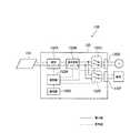
図3に示すように、PV装置130は、PV131と、PCS132とを有する。PCS132は、昇圧コンバータ132Aと、直交変換インバータ132Bと、系統リレー132Cと、系統端子132Dと、自立リレー132Eと、自立端子132Fと、通信部132Gと、制御部132Hとを有する。 As shown in FIG. 3, the
昇圧コンバータ132Aは、PV131から出力される電力(DC電力)をDC/DC変換によって昇圧する。
直交変換インバータ132Bは、昇圧コンバータ132Aから出力される電力(DC電力)をDC/AC変換によって交流電力に変換する。 The
系統リレー132Cは、直交変換インバータ132Bと系統端子132Dとの接続の有無を切り替えるリレースイッチである。 The
系統端子132Dは、系統(又は、系統に接続された機器)とPV装置130とを接続するための端子である。 The
自立リレー132Eは、直交変換インバータ132Bと自立端子132Fとの接続の有無を切り替えるリレースイッチである。 The self-supporting
自立端子132Fは、系統に接続されていない負荷とPV装置130とを接続するための端子(コンセント)である。 The self-supporting
通信部132Gは、EMS200などと通信を行う。第1実施形態において、通信部132Gは、各種メッセージをEMS200に送信する送信部を構成する。通信部132Gは、各種メッセージをEMS200から受信する受信部を構成する。 The communication unit 132G communicates with the
第1実施形態において、EMS200とPV装置130との間において、PV装置130のスペックを示すメッセージ及びPV装置130のステータスを示すメッセージのうち、少なくともいずれかが定義されている。 In the first embodiment, at least one of a message indicating the spec of the
例えば、通信部132Gは、PV装置130のスペックを示すメッセージ及びPV装置130のステータスを示すメッセージのうち、少なくともいずれか一方をEMS200に送信する。或いは、通信部132Gは、PV装置130のステータスを示すメッセージをEMS200から受信する。 For example, the communication unit 132G transmits at least one of a message indicating the spec of the
PV装置130のスペックは、例えば、PCS132が系統に連系された系統連系状態(PCS132が系統端子132Dに接続された状態)における定格電力、PCS132が自立端子132Fに接続された自立運転状態における定格電力、及び、PV131(太陽光パネル)の最大出力電力のうち、少なくともいずれかを含む。 The specifications of the
例えば、系統連系状態において、PV装置130が系統に接続されるため、電流制御によってPV装置130の出力電力が制御される。系統連系状態における定格電力は、PCS132のスペックに依存しており、例えば、4.5kWである。 For example, since the
一方で、自立運転状態において、PV装置130が系統に接続されていないため、電圧制御によってPV装置130の出力電力が制御される。自立運転状態における定格電力は、自立リレー132E及び自立端子132Fのスペックに依存しており、例えば、1.5kWである。 On the other hand, since the
PV131(太陽光パネル)の最大出力電力は、太陽光パネルのスペック及び枚数に依存しており、例えば、4.0kW(200W×20枚)である。ここで、PV131(太陽光パネル)の最大出力電力は、手動で入力されてもよく、過去の発電電力から推定されてもよい。 The maximum output power of the PV 131 (solar panel) depends on the specifications and the number of solar panels, and is, for example, 4.0 kW (200 W × 20 sheets). Here, the maximum output power of the PV 131 (solar panel) may be manually input or may be estimated from past generated power.
PV装置130のステータスは、PCS132が系統に連系されているか否か及びPCS132が自立端子132Fに接続されているか否かのうち、少なくともいずれかを含む。言い換えると、PV装置130のステータスは、系統リレー132CのON/OFF及び自立端子132FのON/OFFのうち、少なくともいずれかを含む。 The status of the
ここで、PV装置130のステータスは、PV装置130から系統への電力供給(逆潮流)が許可されているか否かを含んでもよい。 Here, the status of the
第1実施形態において、通信部132Gは、PV装置130のスペックを示すメッセージの通信に先立って、PV装置130のスペックを示すメッセージを扱う機能の有無を示すメッセージを送信する。或いは、通信部132Gは、PV装置130のステータスを示すメッセージの通信に先立って、PV装置130のステータスを示すメッセージを扱う機能の有無を示すメッセージを送信する。 In the first embodiment, the communication unit 132G transmits a message indicating the presence or absence of a function for handling a message indicating the spec of the
(ネットワーク構成)
以下において、第1実施形態に係るネットワーク構成について説明する。図4は、第1実施形態に係るネットワーク構成を示す図である。(Network configuration)
In the following, a network configuration according to the first embodiment will be described. FIG. 4 is a diagram illustrating a network configuration according to the first embodiment.
図4に示すように、ネットワークは、負荷120、PV装置130、蓄電池装置140、燃料電池装置150、貯湯装置160、EMS200及びユーザ端末300によって構成される。ユーザ端末300は、ユーザ端末310及びユーザ端末320を含む。 As shown in FIG. 4, the network includes a
ユーザ端末310は、EMS200と接続されており、各機器(負荷120、PV装置130、蓄電池装置140、燃料電池装置150、貯湯装置160)の消費エネルギーを可視化するための情報(以下、可視化情報)をウェブブラウザによって表示する。このようなケースにおいて、EMS200は、HTML等の形式で可視化情報を生成して、生成された可視化情報をユーザ端末310に送信する。ユーザ端末310とEMS200との間の接続形式は、有線であってもよく、無線であってもよい。 The
ユーザ端末320は、EMS200と接続されており、可視化情報をアプリケーションによって表示する。このようなケースにおいて、EMS200は、各機器の消費エネルギーを示す情報をユーザ端末320に送信する。ユーザ端末320のアプリケーションは、EMS200から受信する情報に基づいて可視化情報を生成して、生成された可視化情報を表示する。ユーザ端末320とEMS200との間の接続形式は、有線であってもよく、無線であってもよい。 The
上述したように、第1実施形態では、燃料電池装置150及び貯湯装置160が給湯ユニット170を構成する。従って、貯湯装置160は、EMS200と通信を行う機能を有していなくてもよい。このようなケースでは、燃料電池装置150は、貯湯装置160を代理して、貯湯装置160に関するメッセージの通信をEMS200と行う。 As described above, in the first embodiment, the
第1実施形態において、EMS200と各機器(負荷120、PV装置130、蓄電池装置140、燃料電池装置150、貯湯装置160)との間の通信は、所定のプロトコルに従って方式で行われる。所定のプロトコルとしては、例えば、“ECHONET LLite”又は“ECHONET”と呼ばれるプロトコルが挙げられる。しかしながら、実施形態は、これに限定されるものではなく、所定のプロトコルは、“ECHONET Lite”及び“ECHONET”以外のプロトコルであってもよい。 In the first embodiment, communication between the
(EMSの構成)
以下において、第1実施形態に係るEMSについて説明する。図5は、第1実施形態に係るEMS200を示すブロック図である。(Configuration of EMS)
Hereinafter, the EMS according to the first embodiment will be described. FIG. 5 is a block diagram showing the
図5に示すように、EMS200は、受信部210と、送信部220と、制御部230とを有する。 As illustrated in FIG. 5, the
受信部210は、信号線を介して接続された装置から各種信号を受信する。例えば、受信部210は、PV131の発電量を示す情報をPV装置130から受信してもよい。受信部210は、蓄電池141の蓄電量を示す情報を蓄電池装置140から受信してもよい。受信部210は、燃料電池151の発電量を示す情報を燃料電池装置150から受信してもよい。受信部210は、貯湯装置160の貯湯量を示す情報を貯湯装置160から受信してもよい。 The receiving
第1実施形態において、受信部210は、エネルギー料金情報、消費エネルギー予測情報及びPV発電量予測情報を、ネットワーク60を介して各種サーバから受信してもよい。但し、エネルギー料金情報、消費エネルギー予測情報及びPV発電量予測情報は、予めEMS200に記憶されていてもよい。 In the first embodiment, the
第1実施形態において、受信部210は、PV装置130のスペックを示すメッセージ及びPV装置130のステータスを示すメッセージのうち、少なくともいずれか一方をPV装置130から受信する。これによって、受信部210は、PV装置130のスペック又はPV装置130のステータスを取得する。 In the first embodiment, the
第1実施形態において、受信部210は、PV装置130のスペックを示すメッセージの通信に先立って、PV装置130のスペックを示すメッセージを扱う機能の有無を示すメッセージをPV装置130から受信する。或いは、受信部210は、PV装置130のステータスを示すメッセージの通信に先立って、PV装置130のステータスを示すメッセージを扱う機能の有無を示すメッセージをPV装置130から受信する。 In the first embodiment, the
送信部220は、信号線を介して接続された装置に各種信号を送信する。例えば、送信部220は、PV装置130、蓄電池装置140、燃料電池装置150及び貯湯装置160を制御するための信号を各装置に送信する。送信部220は、負荷120を制御するための制御信号を負荷120に送信する。 The
第1実施形態において、送信部220は、PV装置130のステータスを示すメッセージをPV装置130に送信する。これによって、送信部220は、PV装置130のステータスをPV装置130に指示する。詳細には、送信部220は、停電が生じた場合に、自立運転状態を示すメッセージの送信によって、PV装置130が自立運転状態となるようにPV装置130を制御する。或いは、送信部220は、停電から系統が復帰した場合に、系統連系状態を示すメッセージの送信によって、PV装置130が系統連系状態となるようにPV装置130を制御する。或いは、送信部220は、PV装置130のスペックを要求するメッセージをPV装置130に送信する。或いは、送信部220は、PV装置130のステータスを要求するメッセージをPV装置130に送信する。 In the first embodiment, the
第1実施形態において、送信部220は、PV装置130のスペックを示すメッセージの通信に先立って、PV装置130のスペックを示すメッセージを扱う機能の有無を示すメッセージを要求するメッセージをPV装置130に送信する。或いは、送信部220は、PV装置130のステータスを示すメッセージの通信に先立って、PV装置130のステータスを示すメッセージを扱う機能の有無を示すメッセージを要求するメッセージをPV装置130に送信する。 In the first embodiment, prior to communication of a message indicating the spec of the
制御部230は、負荷120、PV装置130、蓄電池装置140、燃料電池装置150及び貯湯装置160を制御する。 The
(メッセージフォーマット)
以下において、第1実施形態に係るメッセージフォーマットについて説明する。図6〜図7は、第1実施形態のメッセージフォーマットの一例を示す図である。(Message format)
The message format according to the first embodiment will be described below. 6 to 7 are diagrams illustrating an example of a message format according to the first embodiment.
第1に、PV装置130のスペックを示すメッセージは、例えば、図6に示すフォーマットを有する。図6に示すように、メッセージは、メッセージ種別のフィールド及びスペックのフィールドを有する。 First, the message indicating the specifications of the
メッセージ種別のフィールドは、メッセージの種別を示しており、第1実施形態では、メッセージがスペックを含むことを示している。 The message type field indicates the message type. In the first embodiment, the message indicates that the message includes a specification.
スペックのフィールドは、PV装置130のスペックを示す。PV装置130のスペックは、上述したように、PCS132が系統に連系された系統連系状態(PCS132が系統端子132Dに接続された状態)における定格電力(系統連系状態)、PCS132が自立端子132Fに接続された自立運転状態における定格電力(自立運転状態)、及び、PV131(太陽光パネル)の最大出力電力(パネル最大出力)のうち、少なくともいずれかを含む。 The specification field indicates the specification of the
例えば、図6に示すように、スペックのフィールドは、定格電力(系統連系状態)及びパネル最大出力の組合せを含んでもよく、定格電力(自立運転状態)及びパネル最大出力の組合せを含んでもよく、定格電力(系統連系状態)、定格電力(自立運転状態)及びパネル最大出力の組合せを含んでもよい。 For example, as shown in FIG. 6, the specification field may include a combination of rated power (system interconnection state) and panel maximum output, or a combination of rated power (self-sustained operation state) and panel maximum output. , A combination of rated power (system interconnection state), rated power (self-sustained operation state), and panel maximum output may be included.
第2に、PV装置130のステータスを示すメッセージは、例えば、図7に示すフォーマットを有する。図7に示すように、メッセージは、メッセージ種別のフィールド及びステータスのフィールドを有する。 Secondly, the message indicating the status of the
メッセージ種別のフィールドは、メッセージの種別を示しており、第1実施形態では、メッセージがステータスを含むことを示している。 The message type field indicates the type of the message. In the first embodiment, the message indicates that the message includes a status.
ステータスのフィールドは、PV装置130のステータスを示す。PV装置130のステータスは、PCS132が系統に連系されているか否か及びPCS132が自立端子132Fに接続されているか否かのうち、少なくともいずれかを含む。言い換えると、PV装置130のステータスは、系統リレー132CのON/OFF及び自立端子132FのON/OFFのうち、少なくともいずれかを含む。PV装置130のステータスは、PV装置130から系統への電力供給(逆潮流)が許可されているか否かを含んでもよい。 The status field indicates the status of the
(管理方法)
以下において、第1実施形態に係る管理方法について説明する。図8は、第1実施形態の管理方法を示すシーケンス図である。(Management method)
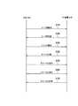
Hereinafter, a management method according to the first embodiment will be described. FIG. 8 is a sequence diagram illustrating the management method according to the first embodiment.
図8に示すように、ステップ10において、EMS200は、PV装置130に対して、PV装置130が対応するコード群を要求するメッセージ(コード群要求)を送信する。コード群要求は、PV装置130のスペックを示すメッセージを扱う機能の有無を示すメッセージを要求するメッセージの一例である。或いは、コード群要求は、PV装置130のステータスを示すメッセージを扱う機能の有無を示すメッセージを要求するメッセージの一例である。 As shown in FIG. 8, in
ステップ20において、PV装置130は、EMS200に対して、PV装置130が対応するコード群を示すメッセージ(コード群応答)を送信する。コード群応答は、PV装置130のスペックを示すメッセージを扱う機能の有無を示すメッセージの一例である。或いは、コード群応答は、PV装置130のステータスを示すメッセージを扱う機能の有無を示すメッセージの一例である。 In step 20, the
ステップ30において、EMS200は、PV装置130に対して、PV装置130のスペックの通知を要求するメッセージ(スペック要求)を送信する。 In step 30, the
ステップ40において、PV装置130は、EMS200に対して、PV装置130のスペックを示すメッセージ(スペック応答)を送信する。 In
ステップ50において、EMS200は、PV装置130のステータスを示すメッセージをPV装置130に送信する。これによって、EMS200は、PV装置130のステータスをPV装置130に指示する。 In
例えば、EMS200は、停電が生じた場合に、自立運転状態を示すメッセージの送信によって、PV装置130が自立運転状態となるようにPV装置130を制御する。或いは、EMS200は、停電から系統が復帰した場合に、系統連系状態を示すメッセージの送信によって、PV装置130が系統連系状態となるようにPV装置130を制御する。 For example, when a power failure occurs, the
ステップ60において、EMS200は、PV装置130に対して、PV装置130のステータスの通知を要求するメッセージ(ステータス要求)を送信する。 In
ステップ70において、PV装置130は、EMS200に対して、PV装置130のステータスを示すメッセージ(ステータス応答)を送信する。 In step 70, the
以上説明したように、第1実施形態では、EMS200とPV装置130との間において、PV装置130のスペックを示すメッセージ及びPV装置130のステータスを示すメッセージのうち、少なくともいずれかが定義されている。従って、これらのメッセージを用いて、PV装置130を適切に制御することができる。また、これらのメッセージを用いて、他の機器(負荷120、蓄電池装置140、燃料電池装置150)を適切に制御することもできる。 As described above, in the first embodiment, at least one of the message indicating the spec of the
例えば、EMS200は、PV装置130のスペックを示すメッセージによって定格出力(自立運転状態)及びパネル最大出力を把握しているため、PV装置130の自立運転状態を適切に制御することができる。また、EMS200は、PV装置130のステータスを示すメッセージによってPV装置130が自立運転状態(自立リレー132E=ON)であることが通知された場合に、PV装置130のスペックを示すメッセージによって定格出力(自立運転状態)及びパネル最大出力を把握していれば、蓄電池装置140、燃料電池装置150及び自立端子132Fに接続された負荷を適切に制御することができる。 For example, since the
同様に、EMS200は、PV装置130のスペックを示すメッセージによって定格出力(系統連系状態)及びパネル最大出力を把握しているため、PV装置130の系統連系状態を適切に制御することができる。また、EMS200は、PV装置130のステータスを示すメッセージによってPV装置130が系統連系状態(系統リレー132C=ON)であることが通知された場合に、PV装置130のスペックを示すメッセージによって定格出力(自立運転状態)及びパネル最大出力を把握していれば、蓄電池装置140、燃料電池装置150及び系統端子132Dに接続された負荷を適切に制御することができる。 Similarly, since the
[その他の実施形態]
本発明は上述した実施形態によって説明したが、この開示の一部をなす論述及び図面は、この発明を限定するものであると理解すべきではない。この開示から当業者には様々な代替実施形態、実施例及び運用技術が明らかとなろう。[Other Embodiments]
Although the present invention has been described with reference to the above-described embodiments, it should not be understood that the descriptions and drawings constituting a part of this disclosure limit the present invention. From this disclosure, various alternative embodiments, examples and operational techniques will be apparent to those skilled in the art.
EMS200は、HEMS(Home Energy Management System)であってもよく、SEMS(Store Energy Management System)であってもよく、BEMS(Building Energy Management System)であってもよく、FEMS(Factory Energy Management System)であってもよい。 The
実施形態では、需要家10は、負荷120、PV装置130、蓄電池装置140、燃料電池装置150及び貯湯装置160を有する。しかしながら、需要家10は、少なくとも、PV装置130を有していればよい。 In the embodiment, the
実施形態では特に触れていないが、PV装置130の初期設定を行うタイミング、停電から復旧したタイミング、PV装置130の電源が投入されたタイミング、EMS200の電源が投入されたタイミング、PV装置130の設定を確認する必要が生じたタイミングにおいて、コード群要求及びコード群応答の送受信が行われることが好ましい。 Although not specifically mentioned in the embodiment, the timing of initial setting of the
実施形態では特に触れていないが、PV装置130は、EMS200からの要求ではなくて、自律的に各種メッセージをEMS200に送信してもよい。例えば、PV装置130は、予め定められた条件が満たされた場合に、各種メッセージをEMS200に送信する。 Although not specifically mentioned in the embodiment, the
実施形態では特に触れていないが、PV装置130は、コード群応答とともに、PV装置130のスペックを示すメッセージをEMS200に送信してもよい。 Although not particularly mentioned in the embodiment, the
10…需要家、20…CEMS、30…変電所、31…配電線、40…スマートサーバ、50…発電所、51…送電線、60…ネットワーク、100…エネルギー管理システム、110…分電盤、120…負荷、130…PV装置、131…PV、132…PCS、140…蓄電池装置、141…蓄電池、142…PCS、150…燃料電池装置、151…燃料電池、152…PCS、160…貯湯装置、170…給湯装置、180、181、182…電流計、200…EMS、210…受信部、220…送信部、230…制御部、300、310、320…ユーザ端末 DESCRIPTION OF
Claims (9)
Translated fromJapanese前記需要家に設けられる制御装置とを備え、
前記複数の機器と前記制御装置との間の通信は、予め定められた所定プロトコルに従った方式で行われ、
前記制御装置は、前記所定プロトコルに従って前記複数の機器と前記制御装置との間で共通化された所定フォーマットを有するメッセージを受信し、
前記複数の機器は、少なくとも、太陽光パネル及び前記太陽光パネルの発電電力を変換するパワーコンディショナーを備える太陽電池装置を含み、
前記制御装置は、前記所定フォーマットを有するメッセージとして、前記パワーコンディショナーの系統連系時の第1定格電力を示す第1メッセージと、前記パワーコンディショナーの自立運転時の第2定格電力を示す第2メッセージとを前記太陽電池装置からそれぞれ識別できる態様で受信可能であることを特徴とする管理システム。A plurality of devices installed in the consumer;
A control device provided in the consumer,
Communication between the plurality of devices and the control device is performed in a manner according to a predetermined protocol,
The control device receives a message having a predetermined format shared between the plurality of devices and the control device according to the predetermined protocol;
The plurality of devices include at least a solar cell device including a solar panel and a power conditioner that converts generated power of the solar panel,
The control device, wherein a message having a predetermined format, wherein the power conditionerand the first message indicating afirst rated powerduring system interconnectionofthesecond showingthesecond Teikakudenforce during autonomous operationof the power conditioner management system characterizedreceivable der Rukotoin a manner that can identify eachand a message from the solar cell device.
前記複数の機器と前記制御装置との間の通信は、予め定められた所定プロトコルに従った方式で行われ、
前記制御装置が、前記所定プロトコルに従って前記複数の機器と前記制御装置との間で共通化された所定フォーマットを有するメッセージを受信するステップAを備え、
前記複数の機器は、少なくとも、太陽光パネル及び前記太陽光パネルの発電電力を変換するパワーコンディショナーを備える太陽電池装置を含み、
前記制御装置は、前記所定フォーマットを有するメッセージとして、前記パワーコンディショナーの系統連系時の第1定格電力を示す第1メッセージと、前記パワーコンディショナーの自立運転時の第2定格電力を示す第2メッセージとを前記太陽電池装置からそれぞれ受信可能であり、
前記制御装置は、受信したメッセージから前記第1定格電力と前記第2定格電力とが識別可能であることを特徴とする管理方法。A management method used in a management system comprising a plurality of devices provided in a consumer and a control device provided in the consumer,
Communication between the plurality of devices and the control device is performed in a manner according to a predetermined protocol,
The control device comprises a step A for receiving a message having a predetermined format shared between the plurality of devices and the control device according to the predetermined protocol,
The plurality of devices include at least a solar cell device including a solar panel and a power conditioner that converts generated power of the solar panel,
Thecontrol device, wherein a message having a predetermined format, wherein the power conditionerand the first message indicating afirst rated powerduring system interconnectionofthesecond showingthesecond Teikakudenforce during autonomous operationof the power conditionerand a messageis capable of receiving fromeach of said solar celldevice,
The control device managementmethod and from the received message to the first rated power and the second rated power and wherein theidentifiable der Rukoto.
前記所定プロトコルに従って前記複数の機器と前記制御装置との間で共通化された所定フォーマットを有するメッセージを受信する受信部を備え、
前記複数の機器は、少なくとも、太陽光パネル及び前記太陽光パネルの発電電力を変換するパワーコンディショナーを備える太陽電池装置を含み、
前記受信部は、前記所定フォーマットを有するメッセージとして、前記パワーコンディショナーの系統連系時の第1定格電力を示す第1メッセージと、前記パワーコンディショナーの自立運転時の第2定格電力を示す第2メッセージとを前記太陽電池装置からそれぞれ受信可能であり、
前記制御装置は、受信したメッセージから前記第1定格電力と前記第2定格電力とが識別可能であることを特徴とする制御装置。A control device that is provided in a consumer provided with a plurality of devices, and that communicates with the plurality of devices in a method according to a predetermined protocol,
A receiving unit for receiving a message having a predetermined format shared between the plurality of devices and the control device according to the predetermined protocol;
The plurality of devices include at least a solar cell device including a solar panel and a power conditioner that converts generated power of the solar panel,
The receiving unit is configured as a message having a predetermined format, wherein the power conditionerand the first message indicating afirst rated powerduring system interconnectionofasecond ofasecond Teikakudenforce during autonomous operationof the power conditionerand a messageis capable of receiving fromeach of said solar celldevice,
Said control device, a controldevice and the received message to the first rated power and the second rated power and wherein theidentifiable der Rukoto.
前記複数の機器と前記制御装置との間の通信は、予め定められた所定プロトコルに従った方式で行われ、
前記所定プロトコルに従って前記複数の機器と前記制御装置との間で共通化された所定フォーマットを有するメッセージを送信する送信部を備え、
前記送信部は、前記所定フォーマットを有するメッセージとして、前記パワーコンディショナーの系統連系時の第1定格電力を示す第1メッセージと、前記パワーコンディショナーの自立運転時の第2定格電力を示す第2メッセージとを前記制御装置にそれぞれ識別できる態様で送信可能であることを特徴とする太陽電池装置。A solar panel and one of a plurality of devices that are provided in a consumer provided with the control device and communicate with the control device in a method according to a predetermined protocol, A solar cell device including a power conditioner that converts electric power,
Communication between the plurality of devices and the control device is performed in a manner according to a predetermined protocol,
A transmission unit for transmitting a message having a predetermined format shared between the plurality of devices and the control device according to the predetermined protocol;
And the transmission unit, said as a message having a predetermined format, wherein the power conditionerand the first message indicating afirst rated powerduring system interconnectionofthesecond showingthesecond Teikakudenforce during autonomous operationof the power conditioner photovoltaic device according to claimtransmittable der Rukotoin a manner that can identify eachand a message to the controller.
Priority Applications (8)
| Application Number | Priority Date | Filing Date | Title |
|---|---|---|---|
| JP2012174459AJP5969304B2 (en) | 2012-08-06 | 2012-08-06 | Management system, management method, control device, and solar cell device |
| EP13827673.8AEP2882072B8 (en) | 2012-08-06 | 2013-08-06 | Management system, management method, control device, and photovoltaic cell device |
| US14/420,186US9979347B2 (en) | 2012-08-06 | 2013-08-06 | Management system, management method, control apparatus, and photovoltaic cell apparatus |
| CN201810391225.2ACN108565297B (en) | 2012-08-06 | 2013-08-06 | Management system, management method, control device, and power conditioner |
| CN201380041895.7ACN104604123A (en) | 2012-08-06 | 2013-08-06 | Management system, management method, control device, and photovoltaic cell device |
| PCT/JP2013/071226WO2014024871A1 (en) | 2012-08-06 | 2013-08-06 | Management system, management method, control device, and photovoltaic cell device |
| JP2016135457AJP6162862B2 (en) | 2012-08-06 | 2016-07-07 | Management system, management method, control device, and power conditioner |
| US15/958,823US10944357B2 (en) | 2012-08-06 | 2018-04-20 | Management system, management method, control apparatus, and photovoltaic cell apparatus |
Applications Claiming Priority (1)
| Application Number | Priority Date | Filing Date | Title |
|---|---|---|---|
| JP2012174459AJP5969304B2 (en) | 2012-08-06 | 2012-08-06 | Management system, management method, control device, and solar cell device |
Related Child Applications (1)
| Application Number | Title | Priority Date | Filing Date |
|---|---|---|---|
| JP2016135457ADivisionJP6162862B2 (en) | 2012-08-06 | 2016-07-07 | Management system, management method, control device, and power conditioner |
Publications (2)
| Publication Number | Publication Date |
|---|---|
| JP2014033593A JP2014033593A (en) | 2014-02-20 |
| JP5969304B2true JP5969304B2 (en) | 2016-08-17 |
Family
ID=50068095
Family Applications (2)
| Application Number | Title | Priority Date | Filing Date |
|---|---|---|---|
| JP2012174459AActiveJP5969304B2 (en) | 2012-08-06 | 2012-08-06 | Management system, management method, control device, and solar cell device |
| JP2016135457AActiveJP6162862B2 (en) | 2012-08-06 | 2016-07-07 | Management system, management method, control device, and power conditioner |
Family Applications After (1)
| Application Number | Title | Priority Date | Filing Date |
|---|---|---|---|
| JP2016135457AActiveJP6162862B2 (en) | 2012-08-06 | 2016-07-07 | Management system, management method, control device, and power conditioner |
Country Status (5)
| Country | Link |
|---|---|
| US (2) | US9979347B2 (en) |
| EP (1) | EP2882072B8 (en) |
| JP (2) | JP5969304B2 (en) |
| CN (2) | CN104604123A (en) |
| WO (1) | WO2014024871A1 (en) |
Families Citing this family (14)
| Publication number | Priority date | Publication date | Assignee | Title |
|---|---|---|---|---|
| JP2016054632A (en)* | 2014-09-04 | 2016-04-14 | パナソニックIpマネジメント株式会社 | Management device for solar battery, photovoltaic power generation system and program |
| WO2016047228A1 (en)* | 2014-09-24 | 2016-03-31 | ソニー株式会社 | Information transmission device and information transmission method |
| US20180041824A1 (en)* | 2015-02-25 | 2018-02-08 | Kyocera Corporation | Power converting apparatus, distribution board, and operation switching method |
| US9397504B1 (en)* | 2015-04-22 | 2016-07-19 | Solarcity Corporation | Hybrid inverter power control system for PV string, battery, grid and back-up loads |
| US10965153B2 (en)* | 2016-02-05 | 2021-03-30 | Duke Energy Corporation | Methods of microgrid communications and connection transitions |
| US20170363666A1 (en)* | 2016-06-16 | 2017-12-21 | Enphase Energy, Inc. | Method and apparatus for energy flow visualization |
| KR101727741B1 (en) | 2016-08-26 | 2017-04-17 | (주) 동보파워텍 | High efficiency photovoltaic inverter system with 3-level boost converter |
| JP6825866B2 (en)* | 2016-09-27 | 2021-02-03 | 京セラ株式会社 | Power management method, power management device, fuel cell device and power management system |
| JP6761042B2 (en)* | 2016-09-27 | 2020-09-23 | 京セラ株式会社 | Power management method, power management device, power conversion device and power management system |
| US11316471B2 (en) | 2016-11-08 | 2022-04-26 | Tesla, Inc. | Manual transfer switch for onsite energy generation and storage systems |
| US10992257B2 (en) | 2017-03-16 | 2021-04-27 | Solarcity Corporation | State of health mechanisms for energy generation systems |
| CN108233421B (en)* | 2018-02-05 | 2020-09-08 | 华为技术有限公司 | Photovoltaic power generation system and photovoltaic power transmission method |
| CN113162106A (en)* | 2020-01-23 | 2021-07-23 | 华为技术有限公司 | Energy storage system and photovoltaic energy storage system |
| CN114256879A (en)* | 2022-01-27 | 2022-03-29 | 青岛海信日立空调系统有限公司 | Photovoltaic air conditioner, control method thereof and photovoltaic air conditioning system |
Family Cites Families (17)
| Publication number | Priority date | Publication date | Assignee | Title |
|---|---|---|---|---|
| JPH1073440A (en)* | 1996-08-30 | 1998-03-17 | Brother Ind Ltd | Vehicle information supply system |
| JP2002152976A (en)* | 2000-11-13 | 2002-05-24 | Sharp Corp | Distributed power supply system |
| JP2006048105A (en)* | 2004-07-30 | 2006-02-16 | East Japan Railway Co | Information distribution system and information distribution network |
| JP4617122B2 (en) | 2004-09-08 | 2011-01-19 | キヤノン株式会社 | Developer transport member, developing device, and process cartridge |
| US8204709B2 (en)* | 2005-01-18 | 2012-06-19 | Solar Sentry Corporation | System and method for monitoring photovoltaic power generation systems |
| JP2006290209A (en) | 2005-04-13 | 2006-10-26 | Hcx:Kk | On-vehicle information processor |
| JP5164245B2 (en)* | 2007-03-29 | 2013-03-21 | 大阪瓦斯株式会社 | Power relay device, power device, and power relay method |
| JP4900606B2 (en)* | 2007-10-22 | 2012-03-21 | シャープ株式会社 | Power interconnection switching system and power interconnection switching method |
| JP2009284590A (en)* | 2008-05-20 | 2009-12-03 | Osaka Gas Co Ltd | Power generation system |
| JP5270315B2 (en) | 2008-11-27 | 2013-08-21 | 株式会社日立製作所 | Automatic meter reading method, automatic meter reading system, automatic meter reading device, and smart meter |
| EP2219276B1 (en)* | 2009-02-11 | 2015-12-02 | SMA Solar Technology AG | Photovoltaic assembly for three-phase feeding into an electric energy supply network |
| JP2010226942A (en)* | 2009-02-26 | 2010-10-07 | Sanyo Electric Co Ltd | Grid interconnection device, grid interconnection system, and power control system |
| WO2010140664A1 (en)* | 2009-06-05 | 2010-12-09 | ソフトバンクモバイル株式会社 | Power supply adapter and power supply system |
| CN201563081U (en)* | 2009-10-30 | 2010-08-25 | 国琏电子(上海)有限公司 | Solar conversion module and power supply system using same |
| KR101084215B1 (en)* | 2009-12-16 | 2011-11-17 | 삼성에스디아이 주식회사 | Energy storage system and its control method |
| US8452461B2 (en) | 2011-05-10 | 2013-05-28 | First Solar, Inc | Control system for photovoltaic power plant |
| JP6252927B2 (en) | 2011-10-18 | 2017-12-27 | パナソニックIpマネジメント株式会社 | Power distribution system and wiring apparatus used therefor |
- 2012
- 2012-08-06JPJP2012174459Apatent/JP5969304B2/enactiveActive
- 2013
- 2013-08-06EPEP13827673.8Apatent/EP2882072B8/enactiveActive
- 2013-08-06WOPCT/JP2013/071226patent/WO2014024871A1/enactiveApplication Filing
- 2013-08-06USUS14/420,186patent/US9979347B2/enactiveActive
- 2013-08-06CNCN201380041895.7Apatent/CN104604123A/enactivePending
- 2013-08-06CNCN201810391225.2Apatent/CN108565297B/enactiveActive
- 2016
- 2016-07-07JPJP2016135457Apatent/JP6162862B2/enactiveActive
- 2018
- 2018-04-20USUS15/958,823patent/US10944357B2/enactiveActive
Also Published As
| Publication number | Publication date |
|---|---|
| CN108565297A (en) | 2018-09-21 |
| EP2882072B1 (en) | 2024-09-25 |
| EP2882072A1 (en) | 2015-06-10 |
| EP2882072B8 (en) | 2024-10-30 |
| CN104604123A (en) | 2015-05-06 |
| US20180248514A1 (en) | 2018-08-30 |
| US10944357B2 (en) | 2021-03-09 |
| US20150229268A1 (en) | 2015-08-13 |
| US9979347B2 (en) | 2018-05-22 |
| JP2016187303A (en) | 2016-10-27 |
| CN108565297B (en) | 2022-08-19 |
| JP6162862B2 (en) | 2017-07-12 |
| EP2882072A4 (en) | 2016-04-13 |
| JP2014033593A (en) | 2014-02-20 |
| WO2014024871A1 (en) | 2014-02-13 |
Similar Documents
| Publication | Publication Date | Title |
|---|---|---|
| JP6162862B2 (en) | Management system, management method, control device, and power conditioner | |
| JP6121607B2 (en) | Management system, management method, control device, and storage battery device | |
| JP6042959B2 (en) | Power management system, power management method, power control device, and storage battery device | |
| JP6339318B2 (en) | Information device, control system, and control method | |
| JP5988757B2 (en) | Power management system, power management method, power control device, and fuel cell device | |
| JP5988758B2 (en) | Power management system, power management method, power control device, and fuel cell device | |
| JP6208457B2 (en) | Control device, control system, and control method | |
| JP6328830B2 (en) | Power conditioner, power management system, power management method, and power management apparatus | |
| JP6121605B2 (en) | Power management system, power management method, power control device, and fuel cell device | |
| JP6286093B2 (en) | Management system, management method, control device, and power conditioner | |
| JP6400143B2 (en) | POWER MANAGEMENT SYSTEM, POWER MANAGEMENT METHOD, FUEL CELL DEVICE, AND POWER CONTROL DEVICE | |
| JP2017042042A (en) | Management system, management method, control device, and storage battery device | |
| JP6359714B2 (en) | Management system, management method, control device, and storage battery device | |
| JP6751693B2 (en) | Control devices, information devices, control systems and control methods | |
| JP2018186700A (en) | Management system, management method, control device, and storage battery device | |
| JP2017175910A (en) | Power management system, power management method, power control apparatus, and distributed power supply | |
| JP2014032940A (en) | Management system, management method, control device, and hot-water supply system | |
| JP2016015340A (en) | Management system, management method, control apparatus, and fuel cell apparatus |
Legal Events
| Date | Code | Title | Description |
|---|---|---|---|
| A621 | Written request for application examination | Free format text:JAPANESE INTERMEDIATE CODE: A621 Effective date:20150115 | |
| A131 | Notification of reasons for refusal | Free format text:JAPANESE INTERMEDIATE CODE: A131 Effective date:20150825 | |
| A521 | Request for written amendment filed | Free format text:JAPANESE INTERMEDIATE CODE: A523 Effective date:20151026 | |
| A131 | Notification of reasons for refusal | Free format text:JAPANESE INTERMEDIATE CODE: A131 Effective date:20151215 | |
| A131 | Notification of reasons for refusal | Free format text:JAPANESE INTERMEDIATE CODE: A131 Effective date:20160329 | |
| A521 | Request for written amendment filed | Free format text:JAPANESE INTERMEDIATE CODE: A523 Effective date:20160412 | |
| TRDD | Decision of grant or rejection written | ||
| A01 | Written decision to grant a patent or to grant a registration (utility model) | Free format text:JAPANESE INTERMEDIATE CODE: A01 Effective date:20160607 | |
| A61 | First payment of annual fees (during grant procedure) | Free format text:JAPANESE INTERMEDIATE CODE: A61 Effective date:20160707 | |
| R150 | Certificate of patent or registration of utility model | Ref document number:5969304 Country of ref document:JP Free format text:JAPANESE INTERMEDIATE CODE: R150 |