JP5968926B2 - Information processing apparatus and information processing program - Google Patents
Information processing apparatus and information processing programDownload PDFInfo
- Publication number
- JP5968926B2 JP5968926B2JP2014010050AJP2014010050AJP5968926B2JP 5968926 B2JP5968926 B2JP 5968926B2JP 2014010050 AJP2014010050 AJP 2014010050AJP 2014010050 AJP2014010050 AJP 2014010050AJP 5968926 B2JP5968926 B2JP 5968926B2
- Authority
- JP
- Japan
- Prior art keywords
- coordinates
- line
- unit
- sight
- correction
- Prior art date
- Legal status (The legal status is an assumption and is not a legal conclusion. Google has not performed a legal analysis and makes no representation as to the accuracy of the status listed.)
- Expired - Fee Related
Links
Images


Landscapes
- User Interface Of Digital Computer (AREA)
Description
Translated fromJapanese本発明は、情報処理装置及び情報処理プログラムに係り、特にタッチ入力の誤動作を補正する情報処理装置及び情報処理プログラムに関する。 The present invention relates to an information processing apparatus and an information processing program, and more particularly to an information processing apparatus and an information processing program that correct a malfunction of touch input.
従来から、文書や画像を印刷可能な複合機(Multifunctional Peripheral, MFP)等の画像形成装置が存在する。 Conventionally, there are image forming apparatuses such as multifunction peripherals (MFPs) capable of printing documents and images.
このような画像形成装置では、表示部のGUIに対する指示をタッチ入力で行うタッチパネルを備えるものが存在する。しかしながら、このようなタッチパネルにおいては、ユーザーが意図しているのとは異なる箇所へタッチ入力してしまうという誤操作が発生することがある。誤操作が発生した場合、指示を取り消し、再度正しいタッチ入力を行うことが必要となり、ユーザーの負担となる。
誤操作は、ユーザーがタッチ入力を正確に行うことで、ある程度防止することが可能である。しかし、例えば、表示部に表示されたキーの画像をタッチ入力することで文字入力を行うソフトウェアキーボード等では、キーの画像が密集して配置される。このような場合、ユーザーが誤操作をしないように正しく操作することは困難である。Some of such image forming apparatuses include a touch panel that performs an instruction to the GUI of the display unit by touch input. However, in such a touch panel, an erroneous operation may occur in which touch input is performed at a location different from the user's intention. When an erroneous operation occurs, it is necessary to cancel the instruction and perform correct touch input again, which is a burden on the user.
An erroneous operation can be prevented to some extent by the user performing accurate touch input. However, for example, in a software keyboard that inputs characters by touch-inputting the key images displayed on the display unit, the key images are densely arranged. In such a case, it is difficult for the user to operate correctly so as not to make an erroneous operation.
ここで、ソフトウェアキーボードの入力について、特許文献1を参照すると、情報を表示する表示部と、表示部の近傍を撮影する撮影部と、撮影部により撮影された画像情報を解析する画像解析部と、画像解析部の解析結果に基づいて、表示部に表示されている情報を拡大表示する拡大処理部とを備える画像表示装置が開示されている。
特許文献1の技術によれば、表示画面の視認性を向上させつつ、誤操作の発生を抑えることができる。Here, referring to
According to the technique of
しかしながら、特許文献1の技術は、視線により表示される箇所を拡大することで、表示される情報が少なくなるという問題があった。 However, the technique of
本発明は、このような状況に鑑みてなされたものであって、上述の問題点を解消することを課題とする。 This invention is made | formed in view of such a situation, Comprising: Let it be a subject to eliminate the above-mentioned problem.
本発明の情報処理装置は、ユーザーによるタッチ入力の操作点の座標を検出するタッチパネルと、前記ユーザーによる前記タッチパネルのタッチ入力の時点から特定の時間の範囲で、前記ユーザーの視線が向けられた前記タッチパネル上の注視点の座標を算出する視線検出手段と、該視線検出手段により算出された前記タッチパネル上の前記注視点の座標から特定の範囲の視線補正領域を算出する視線補正領域算出手段と、前記操作点の座標が、前記視線補正領域算出手段により算出された前記視線補正領域内にあった場合には前記操作点の座標を前記注視点の座標に変更し、前記視線補正領域内になかった場合には前記操作点の座標を変更しない操作座標視線補正手段と、前記操作座標視線補正手段により変更された又は変更されなかった前記操作点の座標に対応する表示を行う表示部とを備え、前記操作座標視線補正手段は、前記操作座標視線補正手段による前記操作点の座標の変更後に、前記ユーザーが前記表示の修正を行うとき、前記表示の修正に対応するタッチ入力の操作点の座標を変更しないことを特徴とする。
本発明の情報処理装置は、前記操作座標視線補正手段による前記操作点の座標の変更後に、前記ユーザーが前記表示の修正を行った場合に、前記時間の範囲と前記視線補正領域の範囲とを修正する視線補正時間領域修正手段を備えることを特徴とする。
本発明の情報処理プログラムは、情報処理装置により実行される情報処理プログラムにおいて、ユーザーによるタッチ入力の操作点の座標を検出し、前記ユーザーによるタッチ入力の時点から特定の時間の範囲で、前記ユーザーの視線が向けられたタッチパネル上の注視点の座標を算出し、算出された前記タッチパネル上の前記注視点の座標から特定の範囲の視線補正領域を算出し、前記操作点の座標が、算出された前記視線補正領域内にあった場合には前記操作点の座標を前記注視点の座標に変更し、前記視線補正領域内になかった場合には前記操作点の座標を変更せず、前記操作点の座標の変更後に、前記ユーザーが表示の修正を行うとき、前記表示の修正に対応するタッチ入力の操作点の座標を変更せず、変更された又は変更されなかった前記操作点の座標に対応する表示を行うことを特徴とする。
本発明の情報処理プログラムは、前記操作点の座標の変更後に、前記ユーザーが前記表示の修正を行った場合に、前記時間の範囲と前記視線補正領域の範囲とを修正することを特徴とする。The information processing apparatus according to the present invention includes a touch panel that detects coordinates of an operation point of a touch input by a user, and the user's line of sight is directed within a specific time range from the time of the touch input of the touch panel by the user. Gaze detection means for calculating the coordinates of the gaze point on the touch panel, and gaze correction area calculation means for calculating a gaze correction area in a specific range from the coordinates of the gaze point on the touch panel calculated by the gaze detection means, If the coordinates of the operation point are within the line-of-sight correction area calculated by the line-of-sight correction area calculation means, the coordinates of the operation point are changed to the coordinates of the gazing point, and are not within the line-of-sight correction area. wherein the operation coordinate sight correcting means does not change the coordinates of the operatingpoint, has not been altered or changed by the operation coordinate sight correcting means when theA display unit that performs display corresponding to the coordinates of the operation point, and the operation coordinate line-of-sight correction unit corrects the display after the operation coordinate line-of-sight correction unit changes the coordinates of the operation point. In this case, the coordinates of the operation point of the touch input corresponding to the correction of the display are not changed .
In the information processing apparatus according to the present invention, when the user corrects the display after changing the coordinates of the operation point by the operation coordinate line-of-sight correction means, the time range and the range of the line-of-sight correction region are obtained. It comprises eye gaze correction time area correction means for correction.
An information processing program of the present invention is an information processing program executed by an information processing apparatus, which detects coordinates of an operation point of a touch input by a user, and the user within a specific time range from the time of the touch input by the user. line of sight and calculates the coordinates of the gaze point on themotor touch paneldirected is, line of sight correction region of the specified range from the coordinates of the gaze point on the calculated the touch panel is calculated, the coordinates of the operation point, calculates The coordinates of the operation point are changed to the coordinates of the gazing point if the coordinates are within the line-of-sight correction area, and the coordinates of the operation points arenot changed when the coordinates are not within the line-of-sight correction area.When the user corrects the display after changing the coordinates of the operating point, the coordinates of the operating point of the touch input corresponding to the correction of the display are not changed, but are changed or not changed. It was andperforming display corresponding to the coordinates of the operation point.
The information processing program according to the present invention corrects the range of time and the range of the line-of-sight correction area when the user corrects the display after changing the coordinates of the operation point. .
本発明によれば、タッチ入力の操作点が視線補正領域内にあった場合は、操作点の座標をユーザーの注視点の座標に変更し、なかった場合には操作点の座標を変更しないことにより、拡大表示を行わなくて誤操作を防止でき、表示できる情報を減少させない情報処理装置を提供することができる。 According to the present invention, when the operation point of the touch input is within the line-of-sight correction region, the coordinate of the operation point is changed to the coordinate of the user's point of interest, and when there is not, the coordinate of the operation point is not changed. Accordingly, it is possible to provide an information processing apparatus that can prevent an erroneous operation without performing enlarged display and does not reduce the information that can be displayed.
<実施の形態>
〔画像形成装置1の全体構成〕
まず、図1及び図2を参照して、画像形成装置1(情報処理装置)の全体の構成について説明する。<Embodiment>
[Overall Configuration of Image Forming Apparatus 1]
First, the overall configuration of the image forming apparatus 1 (information processing apparatus) will be described with reference to FIGS. 1 and 2.
画像形成装置1は、画像処理部11、原稿読取部12、原稿給送部13、搬送部14、ネットワーク送受信部15、操作パネル部16、画像形成部17(画像形成手段)、タイマー部18、記憶部19、及び視線検出部20(視線検出手段)が、制御部10に接続されている。各部は、制御部10によって動作制御される。 The
制御部10は、GPP(General Purpose Processor)、CPU(Central Processing Unit、中央処理装置)、MPU(Micro Processing Unit)、DSP(Digital Signal Processor)、GPU(Graphics Processing Unit)、ASIC(Application Specific Processor、特定用途向けプロセッサー)等の情報処理手段である。
制御部10は、記憶部19のROMやHDDに記憶されている制御プログラムを読み出して、この制御プログラムをRAMに展開させて実行することで、後述する機能ブロックの各手段として動作させられる。また、制御部10は、図示しない外部の端末や操作パネル部16から入力された指示情報に応じて、装置全体を制御する。The
The
画像処理部11は、DSP(Digital Signal Processor)やGPU(Graphics Processing Unit)等の制御演算手段である。画像処理部11は、画像データに対して画像処理を行う手段であり、例えば、拡大縮小、濃度調整、階調調整、画像改善等の各種画像処理を行う。
画像処理部11は、原稿読取部12で読み取られた画像を、記憶部19に印刷データとして記憶する。この際、画像処理部11は、印刷データをPDFやTIFF等のフォーマットのファイル単位に変換することも可能である。The
The
原稿読取部12は、セットされた原稿を読み取る(スキャン)手段である。
原稿給送部13は、原稿読取部12で読み取られる原稿を搬送する手段である。
搬送部14は、給紙カセットから記録紙を搬送し、画像形成部17で画像形成させ、その後にスタックトレイへ搬送する。The
The
The
ネットワーク送受信部15は、LAN、無線LAN、WAN、携帯電話網等の外部ネットワークに接続するためのLANボードや無線送受信機等を含むネットワーク接続手段である。
ネットワーク送受信部15は、データ通信用の回線ではデータを送受信し、音声電話回線では音声信号を送受信する。The network transmission /
The network transmission /
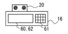
操作パネル部16は、タッチパネル60(入力手段)、ボタン部61(入力手段)、及び表示部62(表示手段)とを備えている。 The
タッチパネル60は、ユーザーが指の押下による操作(以下、「タッチ入力」という。)をした座標等の指示を取得するための静電容量方式、抵抗膜方式、超音波検出方式等のタッチ入力手段である。また、タッチパネル60は、表示部62と一体的に構成されていてもよい。
タッチパネル60は、GUI(Graphical User Interface)等によりユーザーの各種指示を取得する。具体的には、タッチパネル60は、ユーザーがタッチ入力した座標を、操作点200(図3)として検出する。タッチパネル60は、この際、操作点200を、表示部62上の座標と対応する座標として検出してもよい。
なお、タッチパネル60がマルチタッチ対応の場合は、複数の座標を検出してもよい。また、タッチパネル60は、専用のペン等のペン先で入力された座標を検出してもよい。また、タッチパネル60は、ユーザーが押下した押圧を検出してもよい。また、タッチパネル60は、静電容量式や超音波式等の場合、ユーザーの指が非接触でも、表示部62上の座標を操作点200として検出してもよい。この場合、表示部62からの距離を検出してもよい。The
The
Note that when the
ボタン部61は、機械式のスイッチや静電容量式のスイッチ等を含む入力手段である。ボタン部61は、スタートキー、テンキー、コピーやスキャナーやファクシミリ送受信等の動作モードの切り換え、選択された文書の印刷/送信/受信等に係る指示を取得するためのボタン等を含んでいる。 The
表示部62は、LCD(Liquid Crystal Display)、OEL(Organic Electro-Luminescence)、FED(Field Emission Display)等の平面ディスプレイパネル、プロジェクタ、ステータス表示用LED等の表示手段である。表示部62は、各種操作画面を表示する。
表示部62は、GUIの各種画像を表示させることが可能である。また、表示部62には、タッチパネル60上でユーザーに文字等の入力をさせるためのソフトウェアキーボード(Software keyboard)を表示させることも可能である。表示部62は、この際に、操作座標視線補正部110(図3)により変更された又は変更されなかった操作点200の座標に対応する表示を行うことも可能である。なお、表示部62は、記憶部19に記憶された、プレビュー(preview)の画像等も表示可能である。The
The
タイマー部18は、CPU内蔵クロック、リアルタイムクロック、GPS(Global Positioning System)受信機、NTPクライアント等の時刻取得手段である。タイマー部18は、誤差の少ない実時間の時刻情報を取得することが可能である。
また、タイマー部18は、設定された時間の経過後、割り込み等を発生させるタイマーを設定可能である。The
The
画像形成部17は、ユーザーの出力指示により、記憶部19に記憶され、原稿読取部12で読み取られ、又は外部の端末から取得されたデータから記録紙への画像形成を行わせる。 The
記憶部19は、ROM(Read Only Memory)、RAM(Random Access Memory)等の半導体メモリーやHDD(Hard Disk Drive)等の記録媒体を用いた記憶手段である。
記憶部19のROMやHDDには画像形成装置1の動作制御を行うための制御プログラムが記憶されている。これに加えて、記憶部19は、ユーザーのアカウント設定も記憶している。また、記憶部19には、ユーザー毎の文書ボックス等の領域が含まれていてもよい。The
A control program for controlling the operation of the
視線検出部20は、例えば、複数のカメラとDSP等とを備えた視線検出手段である。図2に、画像形成装置1の操作パネル部16と視線検出部20の外観の例を示す。
視線検出部20は、例えば、撮像した画像データから、ユーザーの顔と目とを検出し、更に視線を三次元のベクトル形式等で算出する。視線検出部20は、ユーザーの視線とタッチパネル60との交点の座標(以下、「注視座標」という。)を算出し、注視点220(図3)に設定する。視線検出部20は、この際、ユーザーによるタッチパネル60のタッチ入力の時点の前後の時間範囲210において、注視座標の平均値や、最も注視した時間が長かった座標を、注視点220の座標として算出する。また、視線検出部20は、各注視座標を注視した時間、注視座標の移動のベクトル、注視座標の分散等から、注視点220の算出の確からしさの注視確率等の値を算出してもよい。
なお、時間範囲210は、対象のタッチ入力の前後のタッチ入力の間の時間よりも短い値に設定される。タッチ入力の間隔には個人差があるので、ユーザーが操作パネル部16を使用したときのタッチ入力の間隔の平均値を測定しておき、この実測値に基づいてユーザー毎の時間範囲210を定めてもよい。たとえば、時間範囲210は、タッチ入力の間隔の平均値としてもよいし、この平均値を一定数で割った値としてもよい。
また、視線検出部20は、操作パネル部16に設置することができる。図2に示す例では、視線検出部20が操作パネル部16の端部に設置されているが、操作パネル部16の面上に設置されていてもよく、操作パネル部16に内蔵されていてもよい。また、視線検出部20は、操作パネル部16から離れた位置に設置されていてもよい。また、視線検出部20は、ユーザーを照らす照明部等も備えていてもよい。The line-of-
For example, the line-of-
The
Further, the line-of-
なお、画像形成装置1において、制御部10及び画像処理部11は、GPU内蔵CPU等やチップ・オン・モジュールパッケージのように、一体的に形成されていてもよい。
また、制御部10及び画像処理部11は、RAMやROMやフラッシュメモリー等を内蔵していてもよい。
また、画像形成装置1は、ファクシミリの送受信を行うFAX送受信部を備えていてもよい。In the
The
Further, the
〔画像形成装置1の制御構成〕
次に、図3により、画像形成装置1の制御構成について説明する。
画像形成装置1の制御部10は、視線補正領域算出部100(視線補正領域算出手段)、操作座標視線補正部110(操作座標視線補正手段)、及び視線補正時間領域修正部120(視線補正時間領域修正手段)を備えている。
記憶部19は、操作点200、時間範囲210、注視点220、視線補正領域230、視線補正範囲240を記憶している。[Control Configuration of Image Forming Apparatus 1]
Next, the control configuration of the
The
The
視線補正領域算出部100は、視線検出部20により算出されたタッチパネル60上の注視点220の座標と視線補正範囲240とから視線補正領域230の座標を算出し、記憶部19に記憶する。視線補正領域算出部100は、例えば、注視点220を中心の座標として、視線補正範囲240内の座標を視線補正領域230として算出する。 The line-of-sight correction
操作座標視線補正部110は、操作点200の座標を、視線補正領域算出部100により算出された視線補正領域230に対応して変更する。操作座標視線補正部110は、操作点200が視線補正領域230内にあった場合には、操作点200の座標を注視点220の座標に変更する。また、操作座標視線補正部110は、操作点200が視線補正領域230内になかった場合には、操作点200の座標を変更しない。
また、操作座標視線補正部110は、これら座標補正後に、GUIの各処理を呼び出す。
また、操作座標視線補正部110は、操作座標視線補正部110による操作点200の座標の変更後に、ユーザーが操作点200の座標に対応するタッチ入力の表示の修正を行うとき、表示の修正に対応するタッチ入力の操作点200の座標を変更しないような処理を行ってもよい。The operation coordinate line-of-
Further, the operation coordinate line-of-
The operation coordinate line-of-
視線補正時間領域修正部120は、時間範囲210と視線補正領域230の設定された範囲とを修正する。視線補正時間領域修正部120は、操作座標視線補正部110による操作点200の座標の変更後に、ユーザーがGUIの入力された指示を修正した場合に、これを検出して修正を行う。視線補正時間領域修正部120は、この際、時間範囲210を設定値から変更し、又は、視線補正領域230の広さ若しくは形状を変更する。 The line-of-sight correction time
操作点200は、タッチパネル60により検出された、ユーザーによるタッチ入力の操作点の座標のデータである。操作点200には、表示部62の画面上の表示座標が設定されていてもよい。また、操作点200は、押圧やマルチタッチのタッチ順、移動の向きや加速度等のデータを含んでいてもよい。 The
時間範囲210は、視線検出部20により注視点220の座標を算出する時間(期間)の範囲を指定するデータである。時間範囲210は、ソフトウェアキーボードの場合、タッチパネル60のタッチ入力の時点の前後で、数μ秒〜数秒程度の算出開始時点と算出終了時点との間の範囲を設定可能である。 The
注視点220は、視線検出部20により算出されたユーザーの視線が向けられたタッチパネル60上の注視点の座標のデータである。注視点220には、表示部62の画面上の表示座標等、操作点200と比較可能な座標が設定される。また、注視点220は、各注視座標を注視した時間、注視座標の移動のベクトル、注視座標の分散の値、注視確率等の値等も含まれていてもよい。 The
視線補正領域230は、操作座標視線補正部110により操作点200の座標が変更される領域の座標のデータである。視線補正領域230は、注視点220の座標と、視線補正範囲240とにより、視線補正領域算出部100により算出される。 The line-of-
視線補正範囲240は、視線補正領域算出部100により視線補正領域230を算出するための特定の範囲の座標群や数式等のデータである。視線補正範囲240の座標群等の初期値としては、例えば、注視点220からソフトウェアキーボードの隣接する数個のキーの領域が含まれるような距離の範囲の値であってもよい。また、この範囲の大きさや広さは、視線補正時間領域修正部120により修正されてもよい。
なお、視線補正範囲240は、注視点220を中心とする円形、楕円形、又は任意の範囲の形状を特定するためのデータであってもよい。また、この範囲の形状が楕円形の場合、ソフトウェアキーボードのキーを縦横に含ませる数に応じた長軸と短軸の範囲を設定してもよい。また、この範囲の形状として、ソフトウェアキーボードのキーを複数個含むような領域の形状そのものを指定してもよい。The line-of-
Note that the line-of-
ここで、画像形成装置1の制御部10は、記憶部19に記憶された制御プログラムを実行することで、視線補正領域算出部100、操作座標視線補正部110、及び視線補正時間領域修正部120として機能させられる。
また、上述の画像形成装置1の各部は、本発明の画像形成方法を実行するハードウェア資源となる。Here, the
Each unit of the
〔画像形成装置1による操作座標視線補正処理〕
次に、図4〜図5を参照して、本発明の実施の形態に係る画像形成装置1による操作座標視線補正処理の説明を行う。
本実施形態の操作座標視線補正処理では、視線の先にある注視点220を中心とした視線補正範囲240を、視線補正領域230として算出する。その後、タッチ入力が行われた操作点200が視線補正領域230の内部であった場合、注視点220がタッチされたものとして操作点200の座標を変更する(以下、このように視線により操作点200の座標を特定の条件で補正することを「視線補正する」と呼ぶ。)。操作点200が視線補正領域230の外部であった場合、操作点200の座標を変更せず、そのまま操作箇所がタッチされたものと判断する。
本実施形態の操作座標視線補正処理は、主に制御部10が、記憶部19に記憶されたプログラムを、各部と協働し、ハードウェア資源を用いて実行する。
以下で、図4のフローチャートを参照して、操作座標視線補正処理の詳細をステップ毎に説明する。[Operation Coordinate Gaze Correction Processing by Image Forming Apparatus 1]
Next, the operation coordinate line-of-sight correction processing by the
In the operation coordinate line-of-sight correction process of the present embodiment, a line-of-
In the operation coordinate line-of-sight correction processing of the present embodiment, the
Hereinafter, details of the operation coordinate line-of-sight correction processing will be described step by step with reference to the flowchart of FIG.
(ステップS101)
まず、制御部10が、視線補正領域算出部100として、視線検出開始処理を行う。
制御部10は、GUIによりソフトウェアキーボード等、タッチパネル60によりユーザーの指示を取得する画面が表示された場合、視線検出部20による視線検出を開始させる。これにより、視線検出部20は、視線検出を開始し、注視点220の算出を開始する。(Step S101)
First, the
When the screen for acquiring a user instruction is displayed on the
(ステップS102)
次に、タッチパネル60が、操作点検出処理を行う。
タッチパネル60は、ユーザーによる指の押下によるタッチ入力を検出すると、タッチ入力された操作点200に座標を設定して記憶部19に記憶する。また、タッチパネル60は、このタッチ入力の時点を視線検出部20に通知する。(Step S102)
Next, the
When the
(ステップS103)
次に、視線検出部20が、注視点算出処理を行う。
視線検出部20は、タッチ入力の時点の前後の時間範囲210において、ユーザーの視線が向けられたタッチパネル60上の注視座標のデータを算出する。視線検出部20は、算出した注視座標のデータから、注視点220の座標を算出し、記憶部19に記憶する。視線検出部20は、注視点220の座標を算出したことを、制御部10に通知する。(Step S103)
Next, the
The line-of-
(ステップS104)
次に、制御部10が、視線補正領域算出部100として、視線補正領域算出処理を行う。
制御部10は、視線検出部20からの通知により、注視点220を中心とした視線補正範囲240の座標群等を、視線補正領域230として算出する。
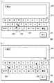
図5(a)の画面例500、及び図5(b)の画面例501には、注視点220を中心としてソフトウェアキーボードのキーの画像を1個〜3個程度含むような距離の円形に算出された視線補正領域230として算出される例が示されている。図5(a)(b)においては、文字の入力欄である表示欄600と、この表示欄600に文字を入力するためのソフトウェアキーボード610とが描画されている。また、ボタン700は、入力を完了したことを示すボタンである。(Step S104)
Next, the
The
In the screen example 500 in FIG. 5A and the screen example 501 in FIG. 5B, the distance is calculated so as to include one to three key images of the software keyboard with the
(ステップS105)
次に、制御部10が、操作座標視線補正部110として、操作点200が視線補正領域230内か否かを判断する。制御部10は、図5(a)の画面例500のように、操作点200が視線補正領域230の内側であった場合には、Yesと判断する。制御部10は、逆に、図5(b)の画面例501のように、操作点200が視線補正領域230の外側であった場合には、Noと判定する。なお、制御部10は、操作点200が補正領域の内部であっても、注視確率等の値が閾値以下であった場合には、Noと判定してもよい。
Yesの場合、制御部10は、処理をステップS106に進める。
Noの場合、制御部10は、処理をステップS107に進める。(Step S105)
Next, the
In the case of Yes, the
In No, the
(ステップS106)
操作点200が視線補正領域230の内側であった場合、制御部10は、操作座標視線補正部110として、操作点座標変更処理を行う。
制御部10は、操作点の座標を注視点220の座標に変更する。制御部10は、この際、操作点の座標を単純に注視点220の座標に変更するのではなく、特定の座標に変更してもよい。この特定の座標は、例えば、注視点220が含まれるソフトウェアキーボードのキーの中心等であってもよい。(Step S106)
When the
The
(ステップS107)
ここで、制御部10は、操作座標視線補正部110として、操作点指示操作実行処理を行う。
制御部10は、操作点200(ステップS106の操作点座標変更処理を行った場合、注視点220に変更された操作点200である。また、ステップS106の操作点座標変更処理を行わなかった場合、タッチ入力された操作点200である。)の座標について、ユーザーのタッチ入力に対応する処理を実行させるようGUIに通知する。これにより、例えば、GUIがソフトウェアキーボードの場合、制御部10は、通知された操作点200の箇所のキーに対応する文字等を、GUIにより入力し、表示部62の入力欄等に表示させる。(Step S107)
Here, the
The
(ステップS108)
次に、制御部10が、視線補正時間領域修正部120として、ユーザー修正ありか否かを判定する。制御部10は、ステップS107において入力され表示された文字等について、ユーザーによる修正があった場合に、Yesと判定する。具体的に説明すると、制御部10は、ソフトウェアキーボードの場合、ユーザーが入力された文字を「修正」のキーを押下する等して、別の文字をタッチ入力した場合には、修正があったため、Yesと判定する。制御部10は、それ以外の場合、例えば、修正せずに他の文字を入力し、又は完了のボタン700を押下した場合には、Noと判定する。
Yesの場合、制御部10は、処理をステップS109に進める。
Noの場合、制御部10は、操作座標視線補正処理を終了する。(Step S108)
Next, the
In the case of Yes, the
In No, the
(ステップS109)
上述のステップS108において、ユーザーによる修正があった場合、制御部10が、視線補正時間領域修正部120として、操作点座標変更抑制処理を行う。
上述の別の文字のタッチ入力は、ユーザー修正時のタッチ入力の操作点の座標に対応するキーに基づいて行われる。
このとき、制御部10は、別の文字のタッチ入力の操作点に対して、操作座標視線補正部110による、操作点座標変更処理を行わないように制御する。つまり、制御部10は、表示の修正に対応するタッチ入力の操作点200の座標を変更しない。
なお、記憶部19に記憶された設定によっては、この処理の際、操作点200の座標の変更の範囲を小さくしたり、そもそも変更しないように構成してもよい。(Step S109)
In step S108 described above, when there is a correction by the user, the
The touch input of another character described above is performed based on a key corresponding to the coordinates of the operation point of the touch input at the time of user correction.
At this time, the
Depending on the settings stored in the
(ステップS110)
次に、制御部10が、視線補正時間領域修正部120として、視線補正時間領域修正処理を行う。
制御部10は、例えば、ソフトウェアキーボードの場合、時間範囲210を設定値から変更することができる。
また、制御部10は、例えば、変更される前の操作点200の座標が修正されたキーの座標であった場合には、変更される前の操作点200の座標が視線補正範囲240に含まれなくなるよう、視線補正範囲240が狭くなるよう修正する。また、制御部10は、逆に、注視点220の座標が、修正されたキーの座標であった場合には、操作点200の座標が視線補正範囲240に含まれるよう視線補正範囲240が広くなるよう修正する。
以上により、本発明の実施の形態に係る操作座標視線補正処理を終了する。(Step S110)
Next, the
For example, in the case of a software keyboard, the
In addition, for example, when the coordinates of the
Thus, the operation coordinate line-of-sight correction processing according to the embodiment of the present invention is completed.
以上のように構成することで、以下のような効果を得ることができる。
従来、特許文献1の技術では、視線の先の画像を拡大表示することで、表示できる情報が少なくなっていた。
これに対して、本発明の実施の形態に係る画像形成装置1は、ユーザーによるタッチ入力の操作点200の座標を検出するタッチパネル60と、ユーザーによるタッチパネル60のタッチ入力の時点からの時間範囲210で、ユーザーの視線が向けられたタッチパネル60上の注視点220の座標を算出する視線検出部20と、視線検出部20により算出されたタッチパネル60上の注視点220の座標から視線補正範囲240の視線補正領域230を算出する視線補正領域算出部100と、操作点200の座標が、視線補正領域算出部100により算出された視線補正領域230内にあった場合には注視点220の座標に変更し、視線補正領域230内になかった場合には操作点200の座標を変更しない操作座標視線補正部110とを備えることを特徴とする。
このように構成することで、表示内容が拡大され表示文字数等が変更されることなく、誤操作を防止したタッチ入力を行うことが可能となる。これにより、表示できる情報が減少することがなくなり、ユーザーの使い勝手を向上させることができる。
また、特許文献1の技術では、視線検出により表示内容が変化することで、ユーザーを混乱させ、ユーザーによる表示内容の読み取り等が困難になり、操作性が悪くなることがあった。
これに対して、本実施形態の画像形成装置1は、視線補正の際、表示部62に表示される表示内容が拡大されないため、ユーザーを混乱させることがなくなり、操作性を向上させることができる。With the configuration described above, the following effects can be obtained.
Conventionally, in the technique of
In contrast, the
With this configuration, it is possible to perform touch input that prevents an erroneous operation without expanding the display contents and changing the number of display characters. As a result, the information that can be displayed does not decrease, and the user-friendliness can be improved.
Further, in the technique of
On the other hand, in the
また、本実施形態の画像形成装置1は、操作座標視線補正部110による操作点200の座標の変更後に、ユーザーが修正を行った場合に、時間範囲210と視線補正範囲240とを修正する視線補正時間領域修正部120を備えることを特徴とする。
このように構成することで、ユーザーの視線補正の精度を向上させ、ユーザーの意図する箇所のキー等を指示できるようになり、操作性を向上させることができる。Further, the
With this configuration, it is possible to improve the accuracy of the user's line-of-sight correction, and to designate a key or the like at a location intended by the user, thereby improving operability.
以上をまとめると、本実施形態の画像形成装置1は、タッチパネルの操作に対して、視線検出の結果に基づいた操作点200を補正することで、誤操作を防止する。つまり、誤操作による修正を防止し、ユーザーが効率的なタッチ入力を行うことが可能となる。これにより:
・ユーザーの意図と異なる箇所へのタッチ入力による誤操作の発生を防止することができる。
・視線検出を利用した操作であっても、ユーザーが混乱することがない。
・視線検出を利用した操作であっても、操作の精度が高い。
・表示部に表示される情報を変更しない。
・視線の先にある範囲内で発生する誤操作を防止する。
・視線の先にある範囲外で意図的に操作することが可能となる。In summary, the
-It is possible to prevent the occurrence of erroneous operations due to touch input at locations different from the user's intention.
・ Users will not be confused by operations using eye gaze detection.
・ Even if the operation uses gaze detection, the accuracy of the operation is high.
・ Do not change the information displayed on the display.
-Prevent misoperations that occur within the line of sight.
-It is possible to operate intentionally outside the range that is beyond the line of sight.
なお、本実施形態においては、ソフトウェアキーボードのキーのタッチ入力を視線補正する例について説明した。しかしながら、本実施形態の操作座標視線補正処理は、ソフトウェアキーボード以外にも、タッチパネル60上でタッチ入力してGUI上の画像等を選択するような処理に全て適用可能である。つまり、制御部10は、例えば、プレビュー画像やサムネイル画像の選択、ファイルの選択といった、選択する画像や文字等が近接している場合に、本実施形態の操作座標視線補正処理を適用するよう制御することが可能である。また、制御部10は、誤操作が少ないGUI上の画面については、本実施形態の操作座標視線補正処理を適用しないように制御することも可能である。
このような構成により、ユーザーの使い勝手をよくすることができる。In the present embodiment, an example in which line-of-sight correction is performed on a touch input of a key on a software keyboard has been described. However, the operation coordinate line-of-sight correction processing according to the present embodiment can be applied to all processing other than the software keyboard, such as touch input on the
With such a configuration, user convenience can be improved.
また、本実施形態においては、表示部62の画面と一体となったタッチパネル60の入力について説明した。しかしながら、表示部62とタッチパネル60とが分離されているような構成であってもよい。この場合にも、視線検出部20は、分離されたタッチパネル60へのユーザーの視線を検知することができる。
これにより、タッチパネル60のコストを削減することができる。Moreover, in this embodiment, the input of the
Thereby, the cost of the
また、本実施形態においては、画像形成装置1のタッチパネルでの誤操作の防止について説明した。
しかしながら、本発明は、画像形成装置以外の情報処理装置にも適用できる。たとえばタッチパネルを備えるスマートフォン、携帯電話、PC(Personal Computer)、PDA(Personal Data Assistant)、テレビジョン等にも適法可能である。In the present embodiment, the prevention of erroneous operation on the touch panel of the
However, the present invention can also be applied to an information processing apparatus other than the image forming apparatus. For example, it can be legally applied to a smart phone equipped with a touch panel, a mobile phone, a PC (Personal Computer), a PDA (Personal Data Assistant), a television, and the like.
また、上記実施の形態の構成及び動作は例であって、本発明の趣旨を逸脱しない範囲で適宜変更して実行することができることは言うまでもない。 Further, the configuration and operation of the above-described embodiment are examples, and it goes without saying that they can be appropriately modified and executed without departing from the gist of the present invention.
1 画像形成装置
10 制御部
11 画像処理部
12 原稿読取部
13 原稿給送部
14 搬送部
15 ネットワーク送受信部
16 操作パネル部
17 画像形成部
18 タイマー部
19 記憶部
20 視線検出部
60 タッチパネル
61 ボタン部
62 表示部
100 視線補正領域算出部
110 操作座標視線補正部
120 視線補正時間領域修正部
200 操作点
210 時間範囲
220 注視点
230 視線補正領域
240 視線補正範囲
500、501 画面例
600 表示欄
610 ソフトウェアキーボード
700 ボタンDESCRIPTION OF
Claims (4)
Translated fromJapanese前記ユーザーによる前記タッチパネルのタッチ入力の時点から特定の時間の範囲で、前記ユーザーの視線が向けられた前記タッチパネル上の注視点の座標を算出する視線検出手段と、
該視線検出手段により算出された前記タッチパネル上の前記注視点の座標から特定の範囲の視線補正領域を算出する視線補正領域算出手段と、
前記操作点の座標が、前記視線補正領域算出手段により算出された前記視線補正領域内にあった場合には前記操作点の座標を前記注視点の座標に変更し、前記視線補正領域内になかった場合には前記操作点の座標を変更しない操作座標視線補正手段と、
前記操作座標視線補正手段により変更された又は変更されなかった前記操作点の座標に対応する表示を行う表示部とを備え、
前記操作座標視線補正手段は、前記操作座標視線補正手段による前記操作点の座標の変更後に、前記ユーザーが前記表示の修正を行うとき、前記表示の修正に対応するタッチ入力の操作点の座標を変更しない
ことを特徴とする情報処理装置。A touch panel that detects the coordinates of the operation point of the touch input by the user;
Gaze detection means for calculating coordinates of a point of gaze on the touch panel to which the user's gaze is directed in a specific time range from the time of touch input of the touch panel by the user;
Gaze correction area calculation means for calculating a gaze correction area of a specific range from the coordinates of the gazing point on the touch panel calculated by the gaze detection means;
If the coordinates of the operation point are within the line-of-sight correction area calculated by the line-of-sight correction area calculation means, the coordinates of the operation point are changed to the coordinates of the gazing point, and are not within the line-of-sight correction area. Operation coordinate line-of-sight correction means that does not change the coordinates of the operation point in the case of,
A display unit that performs display corresponding to the coordinates of the operation point changed or not changed by the operation coordinate line-of-sight correction means,
The operation coordinate line-of-sight correction means, when the user corrects the display after the change of the coordinates of the operation point by the operation coordinate line-of-sight correction means, displays the coordinates of the operation point of the touch input corresponding to the correction of the display. An information processing apparatus that isnot changed .
ことを特徴とする請求項1に記載の情報処理装置。Line-of-sight correction time region correction means for correcting the time range and the range of the line-of-sight correction region when the user corrects the display after changing the coordinates of the operation point by the operation coordinate line-of-sight correction unit. The information processing apparatus according to claim 1, further comprising:
ユーザーによるタッチ入力の操作点の座標を検出し、
前記ユーザーによるタッチ入力の時点から特定の時間の範囲で、前記ユーザーの視線が向けられたタッチパネル上の注視点の座標を算出し、
算出された前記タッチパネル上の前記注視点の座標から特定の範囲の視線補正領域を算出し、
前記操作点の座標が、算出された前記視線補正領域内にあった場合には前記操作点の座標を前記注視点の座標に変更し、前記視線補正領域内になかった場合には前記操作点の座標を変更せず、
前記操作点の座標の変更後に、前記ユーザーが表示の修正を行うとき、前記表示の修正に対応するタッチ入力の操作点の座標を変更せず、
変更された又は変更されなかった前記操作点の座標に対応する表示を行う
ことを特徴とする情報処理プログラム。In an information processing program executed by an information processing device,
Detects the coordinates of the touch input operation point by the user,
Wherein a range of a certain time from the time of the user by the touch input, and calculates the coordinates of the gaze point on themotor touch panel that the user's line of sightdirected,
Calculate a gaze correction area of a specific range from the calculated coordinates of the gazing point on the touch panel,
When the coordinates of the operation point are within the calculated gaze correction area, the coordinates of the operation point are changed to the coordinates of the gazing point, and when the coordinate is not within the gaze correction area, the operation point is changed.Without changing the coordinates of
After the change of the coordinates of the operation point, when the user corrects the display, without changing the coordinates of the operation point of the touch input corresponding to the correction of the display,
An information processing programfor performing display corresponding to the coordinates of the operation point which has been changed or not changed .
ことを特徴とする請求項3に記載の情報処理プログラム。The information processing program according to claim 3.
Priority Applications (4)
| Application Number | Priority Date | Filing Date | Title |
|---|---|---|---|
| JP2014010050AJP5968926B2 (en) | 2014-01-23 | 2014-01-23 | Information processing apparatus and information processing program |
| CN201410841631.6ACN104808836B (en) | 2014-01-23 | 2014-12-30 | Electronic equipment and operation assisting method |
| US14/600,151US9471178B2 (en) | 2014-01-23 | 2015-01-20 | Electronic device, method, and program for supporting touch panel operation |
| EP15152301.6AEP2899611B1 (en) | 2014-01-23 | 2015-01-23 | Electronic device, method, and program for supporting touch panel operation |
Applications Claiming Priority (1)
| Application Number | Priority Date | Filing Date | Title |
|---|---|---|---|
| JP2014010050AJP5968926B2 (en) | 2014-01-23 | 2014-01-23 | Information processing apparatus and information processing program |
Publications (2)
| Publication Number | Publication Date |
|---|---|
| JP2015138426A JP2015138426A (en) | 2015-07-30 |
| JP5968926B2true JP5968926B2 (en) | 2016-08-10 |
Family
ID=53769368
Family Applications (1)
| Application Number | Title | Priority Date | Filing Date |
|---|---|---|---|
| JP2014010050AExpired - Fee RelatedJP5968926B2 (en) | 2014-01-23 | 2014-01-23 | Information processing apparatus and information processing program |
Country Status (1)
| Country | Link |
|---|---|
| JP (1) | JP5968926B2 (en) |
Families Citing this family (1)
| Publication number | Priority date | Publication date | Assignee | Title |
|---|---|---|---|---|
| JP7099444B2 (en) | 2017-04-03 | 2022-07-12 | ソニーグループ株式会社 | Information processing equipment, information processing methods, and programs |
Family Cites Families (5)
| Publication number | Priority date | Publication date | Assignee | Title |
|---|---|---|---|---|
| JP3330239B2 (en)* | 1994-09-22 | 2002-09-30 | アイシン・エィ・ダブリュ株式会社 | Screen touch input device |
| JPH0895702A (en)* | 1994-09-27 | 1996-04-12 | Oki Electric Ind Co Ltd | Method and device for correcting coordinate input detection position |
| JP3705871B2 (en)* | 1996-09-09 | 2005-10-12 | 株式会社リコー | Display device with touch panel |
| JP2009110275A (en)* | 2007-10-30 | 2009-05-21 | Sharp Corp | Display input device and parallax correction method thereof |
| JP2013222438A (en)* | 2012-04-19 | 2013-10-28 | Nec Casio Mobile Communications Ltd | Processing apparatus, and detection position correction method and program |
- 2014
- 2014-01-23JPJP2014010050Apatent/JP5968926B2/ennot_activeExpired - Fee Related
Also Published As
| Publication number | Publication date |
|---|---|
| JP2015138426A (en) | 2015-07-30 |
Similar Documents
| Publication | Publication Date | Title |
|---|---|---|
| CN104808836B (en) | Electronic equipment and operation assisting method | |
| US20140145991A1 (en) | Information processing apparatus installed with touch panel as user interface | |
| JP5932858B2 (en) | Electronic device and operation screen display program | |
| US9354801B2 (en) | Image processing apparatus, image processing method, and storage medium storing program | |
| US9323494B2 (en) | Image processing system, image processing apparatus, portable information terminal, computer-readable storage medium with enhanced display capabilities | |
| US9648181B2 (en) | Touch panel device and image processing apparatus | |
| US9237247B2 (en) | Communication device, method for controlling the same, and non-transitory computer readable medium storing program for the same | |
| JP2018207186A (en) | Portable terminal and electronic system | |
| JP6121564B2 (en) | Information processing apparatus, image forming apparatus, and information processing method | |
| US10645246B2 (en) | Non-transitory computer-readable medium and portable device | |
| JP5968926B2 (en) | Information processing apparatus and information processing program | |
| JP5976708B2 (en) | Electronic equipment and operation support program | |
| JP2018205849A (en) | Mobile terminal and electronic system | |
| JP6665575B2 (en) | program | |
| US11523011B2 (en) | Image forming apparatus and numerical value counting method | |
| JP6176284B2 (en) | Operation display system, operation display device, and operation display program | |
| US20180205839A1 (en) | Image forming apparatus and image forming method | |
| JP6973524B2 (en) | program | |
| JP2011175516A (en) | Input device and input control program | |
| JP2017204189A (en) | Electronic device and image forming apparatus | |
| JP2015069575A (en) | Image processing system, image processing method, and image processing program | |
| US20170013149A1 (en) | Display control device, method for displaying screen, and computer-readable storage medium for computer program | |
| JP2017054396A (en) | Information processing apparatus having touch panel, control method of information processing apparatus, and program | |
| JP2017091200A (en) | Display input device and image forming apparatus having the same | |
| JP2014099089A (en) | Display control device, display control method, and display control program |
Legal Events
| Date | Code | Title | Description |
|---|---|---|---|
| A621 | Written request for application examination | Free format text:JAPANESE INTERMEDIATE CODE: A621 Effective date:20151120 | |
| A871 | Explanation of circumstances concerning accelerated examination | Free format text:JAPANESE INTERMEDIATE CODE: A871 Effective date:20160225 | |
| A975 | Report on accelerated examination | Free format text:JAPANESE INTERMEDIATE CODE: A971005 Effective date:20160330 | |
| A131 | Notification of reasons for refusal | Free format text:JAPANESE INTERMEDIATE CODE: A131 Effective date:20160405 | |
| A521 | Request for written amendment filed | Free format text:JAPANESE INTERMEDIATE CODE: A523 Effective date:20160517 | |
| TRDD | Decision of grant or rejection written | ||
| A01 | Written decision to grant a patent or to grant a registration (utility model) | Free format text:JAPANESE INTERMEDIATE CODE: A01 Effective date:20160607 | |
| A61 | First payment of annual fees (during grant procedure) | Free format text:JAPANESE INTERMEDIATE CODE: A61 Effective date:20160706 | |
| R150 | Certificate of patent or registration of utility model | Ref document number:5968926 Country of ref document:JP Free format text:JAPANESE INTERMEDIATE CODE: R150 | |
| LAPS | Cancellation because of no payment of annual fees |