Movatterモバイル変換


[0]ホーム

URL:


JP5967958B2 - Power supply apparatus and program - Google Patents

Power supply apparatus and program
Download PDF

Info

Publication number
JP5967958B2
JP5967958B2JP2012021133AJP2012021133AJP5967958B2JP 5967958 B2JP5967958 B2JP 5967958B2JP 2012021133 AJP2012021133 AJP 2012021133AJP 2012021133 AJP2012021133 AJP 2012021133AJP 5967958 B2JP5967958 B2JP 5967958B2
Authority
JP
Japan
Prior art keywords
power
electronic device
antenna
cpu
power supply
Prior art date
Legal status (The legal status is an assumption and is not a legal conclusion. Google has not performed a legal analysis and makes no representation as to the accuracy of the status listed.)
Expired - Fee Related
Application number
JP2012021133A
Other languages
Japanese (ja)
Other versions
JP2013162579A (en
Inventor
章弘 田邉
章弘 田邉
Current Assignee (The listed assignees may be inaccurate. Google has not performed a legal analysis and makes no representation or warranty as to the accuracy of the list.)
Canon Inc
Original Assignee
Canon Inc
Priority date (The priority date is an assumption and is not a legal conclusion. Google has not performed a legal analysis and makes no representation as to the accuracy of the date listed.)
Filing date
Publication date
Application filed by Canon IncfiledCriticalCanon Inc
Priority to JP2012021133ApriorityCriticalpatent/JP5967958B2/en
Publication of JP2013162579ApublicationCriticalpatent/JP2013162579A/en
Application grantedgrantedCritical
Publication of JP5967958B2publicationCriticalpatent/JP5967958B2/en
Expired - Fee Relatedlegal-statusCriticalCurrent
Anticipated expirationlegal-statusCritical

Links

Images

Landscapes

Description

Translated fromJapanese

本発明は、電子機器に無線で電力を供給することができる電力供給装置に関する。The present invention relates toa power supply apparatusand the likecapable of supplying power wirelesslyto the electronic apparatus.

近年、コネクタで接続することなく無線によって電力を出力するための一次コイルを持つ給電装置と、給電装置から供給される電力を無線で受け付けるための二次コイルを持つ電子機器とを含む給電システムが知られている。  In recent years, a power feeding system including a power feeding device having a primary coil for outputting power wirelessly without being connected by a connector, and an electronic device having a secondary coil for wirelessly receiving power supplied from the power feeding device. Are known.

このような給電システムにおいて、電子機器は、給電装置から二次コイルを介して受け取る電力によって電池の充電を行うことが知られている(特許文献1)。  In such a power supply system, it is known that an electronic device charges a battery with electric power received from a power supply device via a secondary coil (Patent Document 1).

特開2001−275266号公報JP 2001-275266 A

従来、給電装置は、一次コイルを介して電子機器に電力を供給し、電子機器は、二次コイルを介して給電装置から供給される電力を受電していた。  Conventionally, a power feeding device supplies power to an electronic device via a primary coil, and the electronic device receives power supplied from the power feeding device via a secondary coil.

しかし、一次コイルと二次コイルとの間に金属等の異物が挿入された場合、給電装置から出力される電力が異物に供給されてしまい、その影響によって、給電装置は、電子機器に対して適切な給電を行えなくなってしまうという問題があった。  However, when a foreign object such as metal is inserted between the primary coil and the secondary coil, the power output from the power supply device is supplied to the foreign material, and the power supply device is There was a problem that proper power supply could not be performed.

このような問題を防止するために、給電装置は、給電を行う際に、給電装置の近傍に異物が存在するか否かの検出を行い、異物が検出された場合、異物に電力が供給されないように給電を制御することが必要となってきている。  In order to prevent such problems, the power supply apparatus detects whether or not a foreign object exists in the vicinity of the power supply apparatus when supplying power, and if a foreign object is detected, power is not supplied to the foreign object. Thus, it is necessary to control power feeding.

そこで、本発明は、異物の検出を行うことができ、異物の有無に応じ給電制御を行うことができるようにすることを目的とする。Accordingly, the present invention is the detection of foreign mattercan rowUkoto aims tobe able to perform the power supplycontrol according to the presence or absence of foreign matter.

本発明に係る電力供給装置は、電子機器に無線で電力を供給する電力供給手段と、前記電子機器に無線で電力を供給するためのアンテナと前記電子機器が有するアンテナとの間の共振周波数が所定の周波数になるようにするための共振手段と、前記電子機器に無線で電力を供給するためのアンテナから出力される電力の進行波と前記電子機器に無線で電力を供給するためのアンテナから出力される電力の反射波とに基づいて定在波比を計算する計算手段と、前記電子機器に無線で電力を供給するためのアンテナから出力される電力の進行波と前記電子機器に無線で電力を供給するためのアンテナから出力される電力の反射波とに基づいて計算された定在波比が所定の値以上でない場合に、前記電子機器に無線で電力を供給するためのアンテナから出力される電力の進行波と前記電子機器に無線で電力を供給するためのアンテナから出力される電力の反射波とに基づいて計算される定在波比が1に近い値になるように前記共振手段を調整する調整手段と、異物が存在すると判定した場合に、前記電子機器に無線で供給される電力を制御する制御手段であって、前記電子機器に無線で電力を供給するためのアンテナから出力される電力の進行波と前記電子機器に無線で電力を供給するためのアンテナから出力される電力の反射波とに基づいて計算された定在波比が前記所定の値以上である場合に、異物が存在すると判定し、前記調整手段が前記共振手段を調整した後に計算された定在波比が前記所定の値以上である場合にも、異物が存在すると判定する前記制御手段とを有することを特徴とする
本発明に係るプログラムは、コンピュータを、電子機器に無線で電力を供給する電力供給手段と、前記電子機器に無線で電力を供給するためのアンテナと前記電子機器が有するアンテナとの間の共振周波数が所定の周波数になるようにするための共振手段と、前記電子機器に無線で電力を供給するためのアンテナから出力される電力の進行波と前記電子機器に無線で電力を供給するためのアンテナから出力される電力の反射波とに基づいて定在波比を計算する計算手段と、前記電子機器に無線で電力を供給するためのアンテナから出力される電力の進行波と前記電子機器に無線で電力を供給するためのアンテナから出力される電力の反射波とに基づいて計算された定在波比が所定の値以上でない場合に、前記電子機器に無線で電力を供給するためのアンテナから出力される電力の進行波と前記電子機器に無線で電力を供給するためのアンテナから出力される電力の反射波とに基づいて計算される定在波比が1に近い値になるように前記共振手段を調整する調整手段と、異物が存在すると判定した場合に、前記電子機器に無線で供給される電力を制御する制御手段であって、前記電子機器に無線で電力を供給するためのアンテナから出力される電力の進行波と前記電子機器に無線で電力を供給するためのアンテナから出力される電力の反射波とに基づいて計算された定在波比が前記所定の値以上である場合に、異物が存在すると判定し、前記調整手段が前記共振手段を調整した後に計算された定在波比が前記所定の値以上である場合にも、異物が存在すると判定する前記制御手段として機能させるためのプログラムである。
Thepower supply device according to the present invention includes apower supply unitthat wirelessly supplies power to an electronic device, an antenna for supplying power to the electronic device wirelessly, and a resonance frequency between the antenna of the electronic device. Resonance means for achieving a predetermined frequency, a traveling wave of power output from an antenna for supplying power to the electronic device wirelessly, and an antenna for supplying power to the electronic device wirelessly Calculation means for calculating a standing wave ratio based on the reflected wave of the output power, a traveling wave of power output from an antenna for supplying power to the electronic device wirelessly, and a wireless to the electronic device An antenna for wirelessly supplying power to the electronic device when a standing wave ratio calculated based on a reflected wave of power output from the antenna for supplying power is not equal to or greater than a predetermined value So that the standing wave ratio calculated based on the traveling wave of power output from the antenna and the reflected wave of power output from the antenna for supplying power to the electronic device wirelessly becomes a value close to 1. An adjustment unit that adjusts the resonance unit; and a control unit that controls power supplied wirelessly to the electronic device when it is determined that a foreign object is present. A standing wave ratio calculated based on a traveling wave of power output from the antenna and a reflected wave of power output from the antenna for wirelessly supplying power to the electronic device is greater than or equal to the predetermined value. The control means for determining that there is a foreign object even if the standing wave ratio calculated after the adjustment means has adjusted the resonance means is greater than or equal to the predetermined value. Special features To.
The program according to the present invention includes a computer, a power supply unit that wirelessly supplies power to an electronic device, an antenna for supplying power to the electronic device wirelessly, and a resonance frequency between the antenna of the electronic device Resonance means for setting the frequency to a predetermined frequency, a traveling wave of power output from an antenna for supplying power to the electronic device wirelessly, and an antenna for supplying power to the electronic device wirelessly A calculation means for calculating a standing wave ratio based on a reflected wave of power output from the antenna, a traveling wave of power output from an antenna for supplying power to the electronic device wirelessly, and a wireless to the electronic device When the standing wave ratio calculated based on the reflected wave of the power output from the antenna for supplying the power at is not greater than a predetermined value, the power is supplied to the electronic device wirelessly The standing wave ratio calculated based on the traveling wave of the power output from the antenna and the reflected wave of the power output from the antenna for wirelessly supplying power to the electronic device is close to 1. Adjusting means for adjusting the resonance means, and control means for controlling the power supplied to the electronic device wirelessly when it is determined that a foreign object is present, wherein the power is supplied to the electronic device wirelessly A standing wave ratio calculated based on a traveling wave of power output from an antenna for performing power and a reflected wave of power output from an antenna for wirelessly supplying power to the electronic device is the predetermined value In the case of the above, it is determined that there is a foreign object, and it is determined that there is a foreign object even when the standing wave ratio calculated after the adjustment unit adjusts the resonance unit is greater than or equal to the predetermined value. As a control means Is a program to function.

本発明によれば、異物の検出を行うことができ、異物の有無に応じ給電制御を行うことができる。According to the present invention, the detection of the foreign mattercan rowUkoto, power supplycontrol can andTURMERIC rowsaccording to the presence or absence of the foreign substance.

実施例1における給電システムの一例を示す図である。It is a figure which shows an example of the electric power feeding system in Example 1. FIG.実施例1における給電システムのブロック図の一例を示す図である。It is a figure which shows an example of the block diagram of the electric power feeding system in Example 1. FIG.実施例1における給電装置100の整合回路104の構成の一例を示す図である。3 is a diagram illustrating an example of a configuration of amatching circuit 104 of thepower supply apparatus 100 according to Embodiment 1. FIG.実施例1における給電装置100の反射電力検出回路112の構成の一例を示す図である。FIG. 3 is a diagram illustrating an example of a configuration of a reflectedpower detection circuit 112 of thepower supply apparatus 100 according to the first embodiment.実施例1における給電装置によって行われる異物検出処理の一例を示すフローチャートである。3 is a flowchart illustrating an example of a foreign object detection process performed by the power supply apparatus according to the first embodiment.実施例1における給電装置によって行われる調整処理の一例を示すフローチャートである。6 is a flowchart illustrating an example of adjustment processing performed by the power supply apparatus according to the first embodiment.実施例2における給電装置によって行われる調整処理の一例を示すフローチャートである。10 is a flowchart illustrating an example of adjustment processing performed by the power supply apparatus according to the second embodiment.実施例3における給電装置100の整合回路104の構成の一例を示す図である。FIG. 10 is a diagram illustrating an example of a configuration of amatching circuit 104 of apower feeding apparatus 100 according to a third embodiment.

[実施例1]
以下、本発明の実施例1について、図面を参照して詳細に説明する。実施例1に係る給電システムは、図1に示すように給電装置100と、電子機器200とを有する。実施例1における給電システムにおいて、給電装置100と電子機器200との距離が所定の範囲内に存在する場合、給電装置100は、電子機器200に無線給電を行う。また、給電装置100と電子機器200との距離が所定の範囲内に存在する場合、電子機器200は、給電装置100から出力される電力を無線により受け取る。また、給電装置100と電子機器200との距離が所定の範囲内に存在しない場合、電子機器200は、給電装置100から電力を受け取ることができない。なお、所定の範囲とは、給電装置100と電子機器200とが通信を行うことができる範囲であるものとする。
[Example 1]
Hereinafter, Example 1 of the present invention will be described in detail with reference to the drawings. The power supply system according to the first embodiment includes apower supply apparatus 100 and anelectronic device 200 as illustrated in FIG. In the power supply system according to the first embodiment, when the distance between thepower supply apparatus 100 and theelectronic device 200 is within a predetermined range, thepower supply apparatus 100 performs wireless power supply to theelectronic device 200. When the distance between thepower supply apparatus 100 and theelectronic device 200 is within a predetermined range, theelectronic device 200 receives the power output from thepower supply apparatus 100 wirelessly. Further, when the distance between thepower supply apparatus 100 and theelectronic device 200 does not exist within a predetermined range, theelectronic device 200 cannot receive power from thepower supply apparatus 100. Note that the predetermined range is a range in which thepower supply apparatus 100 and theelectronic device 200 can communicate with each other.

なお、給電装置100は、複数の電子機器に対しても、並行して電力を無線で供給することができるものであってもよいものとする。  Note that thepower supply apparatus 100 may be capable of wirelessly supplying power to a plurality of electronic devices in parallel.

電子機器200は、カメラ等の撮像装置であってもよく、音声データや映像データの再生を行う再生装置であってもよい。また、電子機器200は、携帯電話やスマートフォンのようなモバイル機器であってもよいものとする。また、電子機器200は、電池211を含む電池パックであってもよい。  Theelectronic device 200 may be an imaging device such as a camera or a playback device that plays back audio data and video data. Theelectronic device 200 may be a mobile device such as a mobile phone or a smartphone.Electronic device 200 may be a batterypack including battery 211.

また、電子機器200は、給電装置100から供給される電力によって駆動する車のような装置であってもよい。また、電子機器200は、テレビジョン放送を受信する装置、映像データを表示するディスプレイ、またはパーソナルコンピュータであってもよいものとする。また、電子機器200は、電池211が装着されていない場合であっても、給電装置100から供給される電力を用いて動作する装置であってもよい。  Further, theelectronic device 200 may be a device such as a car that is driven by electric power supplied from thepower supply device 100. Theelectronic device 200 may be a device that receives a television broadcast, a display that displays video data, or a personal computer.Electronic device 200 may be a device that operates using power supplied frompower supply device 100 even whenbattery 211 is not attached.

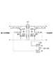
図2は、実施例1に係る給電システムのブロック図を示す。給電装置100は、図2に示すように、変換部101、発振器102、電力生成部103、整合回路104、変復調回路105、給電アンテナ106、CPU107、ROM108、RAM109、表示部110、操作部111及び反射電力検出回路112を有する。  FIG. 2 is a block diagram of the power feeding system according to the first embodiment. As shown in FIG. 2, thepower feeding apparatus 100 includes aconversion unit 101, anoscillator 102, apower generation unit 103, amatching circuit 104, a modulation /demodulation circuit 105, apower feeding antenna 106, aCPU 107, aROM 108, aRAM 109, adisplay unit 110, anoperation unit 111, and A reflectedpower detection circuit 112 is included.

変換部101は、不図示のAC電源と給電装置100とが接続されている場合、不図示のAC電源から供給される交流電力を直流電力に変換し、変換した直流電力を給電装置100に供給する。  When the AC power supply (not shown) and thepower supply apparatus 100 are connected, theconversion unit 101 converts AC power supplied from the AC power supply (not shown) into DC power, and supplies the converted DC power to thepower supply apparatus 100. To do.

発振器102は、変換部101から供給される電力をCPU107によって設定された目標値に対応する電力に変換するように電力生成部103を制御するために用いられる周波数を発振する。なお、発振器102は、水晶振動子等を用いる。  Theoscillator 102 oscillates a frequency used to control thepower generation unit 103 so as to convert the power supplied from theconversion unit 101 into power corresponding to the target value set by theCPU 107. Theoscillator 102 uses a crystal resonator or the like.

電力生成部103は、変換部101から供給される電力と、発振器102によって発振される周波数とに基づいて、給電アンテナ106を介して外部に出力するための電力を生成する。電力生成部103は、内部にFET等を有し、発振器102によって発振される周波数に応じて、内部のFETのソース・ドレインの端子間に流れる電流を制御し、外部に出力するための電力を生成する。なお、電力生成部103によって生成された電力は、反射電力検出回路112を介して、整合回路104に供給される。また、電力生成部103によって生成される電力には、第1の電力と、第2の電力とがある。  Thepower generation unit 103 generates power to be output to the outside via thefeeding antenna 106 based on the power supplied from theconversion unit 101 and the frequency oscillated by theoscillator 102. Thepower generation unit 103 includes an FET or the like inside, controls the current flowing between the source and drain terminals of the internal FET according to the frequency oscillated by theoscillator 102, and generates power for output to the outside. Generate. The power generated by thepower generation unit 103 is supplied to thematching circuit 104 via the reflectedpower detection circuit 112. Further, the power generated by thepower generation unit 103 includes a first power and a second power.

第1の電力は、給電装置100が電子機器200と無線通信を行うために電子機器200に供給するための電力である。第2の電力は、給電装置100が電子機器200に対して給電を行う場合に電子機器200に供給するための電力である。例えば、第1の電力は、1W以下の電力であり、第2の電力は、2W〜10Wまでの電力である。なお、第2の電力は、10W以上の電力であってもよい。なお、第1の電力は、第2の電力よりも低い電力であるものとする。また、第1の電力は、給電装置100が無線通信を行うために用いられる電力であれば、1W以下の電力に限られないものとする。  The first power is power that thepower supply apparatus 100 supplies to theelectronic device 200 in order to perform wireless communication with theelectronic device 200. The second power is power that is supplied to theelectronic device 200 when thepower supply apparatus 100 supplies power to theelectronic device 200. For example, the first power is 1 W or less, and the second power is 2 W to 10 W. Note that the second power may be 10 W or more. Note that the first power is lower than the second power. In addition, the first power is not limited to 1 W or less as long as the power is used for thepower supply apparatus 100 to perform wireless communication.

なお、給電装置100が第1の電力を電子機器200に供給している場合、給電装置100は、給電アンテナ106を介して電子機器200とNFC(Near Field Communication)規格に対応する無線通信を行うことができる。しかし、給電装置100が第2の電力を電子機器200に供給している場合、給電装置100は、給電アンテナ106を介して電子機器200とNFC規格に対応する無線通信を行うことができないものとする。  Note that when thepower supply apparatus 100 supplies the first electric power to theelectronic device 200, thepower supply apparatus 100 performs wireless communication corresponding to the NFC (Near Field Communication) standard with theelectronic device 200 via thepower supply antenna 106. be able to. However, when thepower supply apparatus 100 supplies the second power to theelectronic device 200, thepower supply apparatus 100 cannot perform wireless communication corresponding to the NFC standard with theelectronic apparatus 200 via thepower supply antenna 106. To do.

整合回路104は、発振器102によって発振される周波数に応じて、給電アンテナ106と、給電装置100に対応する装置が有する受電アンテナとの間で共振を行うための共振回路である。また、整合回路104は、電力生成部103と給電アンテナ106との間のインピーダンスマッチングを行うための回路である。  Thematching circuit 104 is a resonance circuit for performing resonance between thepower feeding antenna 106 and the power receiving antenna included in the device corresponding to thepower feeding device 100 in accordance with the frequency oscillated by theoscillator 102. Thematching circuit 104 is a circuit for performing impedance matching between thepower generation unit 103 and the feedingantenna 106.

図3に整合回路104の構成を示す。整合回路104は、図3に示すように、可変コンデンサ301、可変コンデンサ302、コイル303及び抵抗304を有する。  FIG. 3 shows the configuration of thematching circuit 104. As illustrated in FIG. 3, thematching circuit 104 includes a variable capacitor 301, avariable capacitor 302, acoil 303, and a resistor 304.

CPU107は、発振器102によって発振される周波数を、共振周波数fに設定するために、可変コンデンサ301や可変コンデンサ302の値を制御する。なお、共振周波数fは、給電装置100と、給電装置100によって給電される装置とが共振を行うために用いられる周波数である。  TheCPU 107 controls the values of the variable capacitor 301 and thevariable capacitor 302 in order to set the frequency oscillated by theoscillator 102 to the resonance frequency f. Note that the resonance frequency f is a frequency used for resonance between thepower feeding device 100 and a device fed by thepower feeding device 100.

共振周波数fは、下記の数式(1)によって示されるものとする。Lは、整合回路104のインダクタンス、Cは、整合回路104のキャパシタンスを示す。  The resonance frequency f is assumed to be represented by the following mathematical formula (1). L represents the inductance of thematching circuit 104, and C represents the capacitance of thematching circuit 104.

Figure 0005967958
Figure 0005967958

また、可変コンデンサ301及び可変コンデンサ302は、インピーダンスマッチングを行うために用いられる。  The variable capacitor 301 and thevariable capacitor 302 are used for impedance matching.

CPU107は、発振器102によって発振される周波数が、共振周波数fになるように整合回路104に含まれる可変コンデンサ301や可変コンデンサ302を制御する。また、整合回路104のキャパシタンスCを変更する方法として、複数のコンデンサを並列に配置し、リレーICなどで切り替えるようにしてもよい。  TheCPU 107 controls the variable capacitor 301 and thevariable capacitor 302 included in thematching circuit 104 so that the frequency oscillated by theoscillator 102 becomes the resonance frequency f. Further, as a method of changing the capacitance C of thematching circuit 104, a plurality of capacitors may be arranged in parallel and switched by a relay IC or the like.

また、整合回路104は、可変コンデンサ301、可変コンデンサ302、コイル303及び抵抗304以外にも、さらに他の素子を有していてもよいものとする。  Thematching circuit 104 may further include other elements in addition to the variable capacitor 301, thevariable capacitor 302, thecoil 303, and the resistor 304.

なお、共振周波数fは、商用周波数である50/60Hzであってもよく、10〜数十MHzであってもよく、13.56MHzの周波数であってもよいものとする。  The resonance frequency f may be a commercial frequency of 50/60 Hz, 10 to several tens of MHz, or 13.56 MHz.

さらに、整合回路104は、給電アンテナ106に流れる電流及び給電アンテナ106に供給される電圧の変化を検出することもできる。  Further, thematching circuit 104 can detect a change in the current flowing through thepower feeding antenna 106 and the voltage supplied to thepower feeding antenna 106.

なお、発振器102によって発振される周波数が、共振周波数fに設定された状態において、電力生成部103によって生成された電力は、整合回路104を介して給電アンテナ106に供給される。  Note that, in a state where the frequency oscillated by theoscillator 102 is set to the resonance frequency f, the power generated by thepower generation unit 103 is supplied to thefeeding antenna 106 via thematching circuit 104.

変復調回路105は、給電装置100と電子機器200との間で、NFC規格に対応する無線通信を行うために用いられる回路である。給電装置100が電子機器200を制御するための制御データ(以下、コマンドと呼ぶ。)を電子機器200に送信する場合、変復調回路105は、NFC規格に対応するプロトコルに基づいて、電力生成部103によって生成された電力の変調を行う。  Themodem circuit 105 is a circuit used for performing wireless communication corresponding to the NFC standard between thepower supply apparatus 100 and theelectronic device 200. When thepower supply apparatus 100 transmits control data (hereinafter referred to as a command) for controlling theelectronic device 200 to theelectronic device 200, themodem circuit 105 is based on a protocol corresponding to the NFC standard. Modulates the power generated by

変復調回路105は、電力生成部103によって発生された電力を、振幅変位を利用したASK(Amplitude Shift Keying)変調によって、パルス信号に変換する。コマンドとして変換されたパルス信号は、給電アンテナ106を介して電子機器200に送信される。電子機器200に送信されたパルス信号は、電子機器200に解析されることによって、「1」の情報と、「0」の情報とを含むビットデータとして電子機器200に検出される。なお、ASK変調は、振幅変位を利用した変調であり、ICカードと、カードリーダとの通信等で用いられる。  Themodem circuit 105 converts the power generated by thepower generation unit 103 into a pulse signal by ASK (Amplitude Shift Keying) modulation using amplitude displacement. The pulse signal converted as a command is transmitted to theelectronic device 200 via thepower feeding antenna 106. The pulse signal transmitted to theelectronic device 200 is detected by theelectronic device 200 as bit data including “1” information and “0” information by being analyzed by theelectronic device 200. ASK modulation is modulation using amplitude displacement, and is used for communication between an IC card and a card reader.

さらに、変復調回路105は、所定の符合化方式に対応する符合化回路を有する。  Further, themodem circuit 105 has an encoding circuit corresponding to a predetermined encoding system.

変復調回路105は、整合回路104によって検出される給電アンテナ106に流れる電流の変化に応じて、電子機器200に送信したコマンドに対する電子機器200からの応答データや電子機器200からの制御データを符号化回路により復調することができる。このことによって、変復調回路105は、電子機器200に送信したコマンドに対する応答データや電子機器200から送信される制御データを、負荷変調方式に基づいて、電子機器200から受信することができる。  The modulation /demodulation circuit 105 encodes response data from theelectronic device 200 to the command transmitted to theelectronic device 200 and control data from theelectronic device 200 in accordance with a change in the current flowing through thepower supply antenna 106 detected by thematching circuit 104. Demodulated by the circuit. Thus, themodem circuit 105 can receive response data for the command transmitted to theelectronic device 200 and control data transmitted from theelectronic device 200 from theelectronic device 200 based on the load modulation method.

変復調回路105は、CPU107からの指示に応じてコマンドを電子機器200に送信する。さらに、変復調回路105は、電子機器200から応答データや制御データを受信した場合、受信した応答データや制御データを復調してCPU107に供給する。  Themodem circuit 105 transmits a command to theelectronic device 200 in accordance with an instruction from theCPU 107. Further, when receiving response data and control data from theelectronic device 200, themodem circuit 105 demodulates the received response data and control data and supplies the demodulated data to theCPU 107.

給電アンテナ106は、電力生成部103により生成された電力を外部に出力するためのアンテナである。給電装置100は、給電アンテナ106を介して電子機器200に電力を供給したり、給電アンテナ106を介して電子機器200にコマンドを送信する。また、給電装置100は、給電アンテナ106を介して、電子機器200から制御データ及び電子機器200に送信したコマンドに対応する応答データを受信する。  Thepower feeding antenna 106 is an antenna for outputting the power generated by thepower generation unit 103 to the outside. Thepower supply apparatus 100 supplies power to theelectronic device 200 via thepower supply antenna 106 or transmits a command to theelectronic device 200 via thepower supply antenna 106. In addition, thepower supply apparatus 100 receives control data from theelectronic device 200 and response data corresponding to the command transmitted to theelectronic device 200 via thepower supply antenna 106.

CPU(Central Processing Unit)107は、ROM108に記憶されているコンピュータプログラムを実行することによって、給電装置100を制御する。CPU107は、電力生成部103を制御することによって電子機器200に供給する電力を制御する。  A CPU (Central Processing Unit) 107 controls thepower supply apparatus 100 by executing a computer program stored in theROM 108. TheCPU 107 controls the power supplied to theelectronic device 200 by controlling thepower generation unit 103.

また、CPU107は、カウンタ107aを有する。カウンタ107aは、給電装置100で行われる処理に関する回数をカウントする。また、カウンタ107aによってカウントされる回数に対する閾値は、ROM108にあらかじめ記録されている。また、カウンタ107aによって計測される時間を示す情報は、RAM109に記録される。  TheCPU 107 has acounter 107a. Thecounter 107 a counts the number of times related to processing performed by thepower supply apparatus 100. Further, a threshold for the number of times counted by thecounter 107a is recorded in theROM 108 in advance. Information indicating the time measured by thecounter 107 a is recorded in theRAM 109.

ROM108は、給電装置100を制御するコンピュータプログラム及び給電装置100に関するパラメータ等の情報を記憶する。ROM108には、補正テーブルが記録されている。なお、補正テーブルとは、電子機器200のステータスデータと、VSWRに対応する補正値とが関連付けられているテーブルである。なお、電子機器200のステータスデータには、電子機器200の動作状態を示す情報や電子機器200の移動状態を示す情報等が含まれる。  TheROM 108 stores information such as a computer program for controlling thepower supply apparatus 100 and parameters related to thepower supply apparatus 100. A correction table is recorded in theROM 108. The correction table is a table in which the status data of theelectronic device 200 is associated with the correction value corresponding to the VSWR. The status data of theelectronic device 200 includes information indicating the operating state of theelectronic device 200, information indicating the moving state of theelectronic device 200, and the like.

RAM109は、書き換え可能なメモリであり、給電装置100を制御するコンピュータプログラム、給電装置100に関するパラメータ等の情報、変復調回路105によって電子機器200から受信されたデータ等を記録する。  TheRAM 109 is a rewritable memory, and records a computer program for controlling thepower supply apparatus 100, information on parameters related to thepower supply apparatus 100, data received from theelectronic device 200 by themodem circuit 105, and the like.

表示部110は、RAM109から供給される映像データ及びROM108から供給される映像データのいずれか一つを表示する。  Thedisplay unit 110 displays one of the video data supplied from theRAM 109 and the video data supplied from theROM 108.

操作部111は、給電装置100を操作するためのユーザインターフェースを提供する。操作部111は、給電装置100の電源ボタン及び給電装置100のモード切換ボタン等を有し、各ボタンはスイッチ、タッチパネル等により構成される。CPU107は、操作部111を介して入力されたユーザの指示に従って給電装置100を制御する。  Theoperation unit 111 provides a user interface for operating thepower supply apparatus 100. Theoperation unit 111 includes a power button of thepower supply apparatus 100, a mode switching button of thepower supply apparatus 100, and the like, and each button includes a switch, a touch panel, and the like. TheCPU 107 controls thepower supply apparatus 100 in accordance with a user instruction input via theoperation unit 111.

反射電力検出回路112は、給電アンテナ106によって出力される電力の進行波の振幅電圧V1を示す情報と、給電アンテナ106によって出力される電力の反射波の振幅電圧V2を示す情報とを検出する。反射電力検出回路112によって検出された振幅電圧V1を示す情報及び振幅電圧V2を示す情報は、CPU107に供給される。CPU107は、反射電力検出回路112から供給された振幅電圧V1を示す情報及び振幅電圧V2を示す情報をRAM109に記録する。  The reflectedpower detection circuit 112 detects information indicating the amplitude voltage V1 of the traveling wave of power output from thepower supply antenna 106 and information indicating the amplitude voltage V2 of the reflected wave of power output from thepower supply antenna 106. Information indicating the amplitude voltage V1 and information indicating the amplitude voltage V2 detected by the reflectedpower detection circuit 112 are supplied to theCPU 107. TheCPU 107 records information indicating the amplitude voltage V <b> 1 and information indicating the amplitude voltage V <b> 2 supplied from the reflectedpower detection circuit 112 in theRAM 109.

反射電力検出回路112の構成の一例を、図4に示す。反射電力検出回路112は、図4に示すように、トロイダルコア401、コンデンサ402、コンデンサ403、ダイオード404、抵抗405、コンデンサ406、コンデンサ407、ダイオード408及び抵抗409を有する。さらに、反射電力検出回路112は、A/Dコンバータ410及びA/Dコンバータ411を有する。  An example of the configuration of the reflectedpower detection circuit 112 is shown in FIG. As shown in FIG. 4, the reflectedpower detection circuit 112 includes atoroidal core 401, a capacitor 402, acapacitor 403, adiode 404, aresistor 405, a capacitor 406, acapacitor 407, adiode 408, and aresistor 409. Further, the reflectedpower detection circuit 112 includes an A /D converter 410 and an A /D converter 411.

反射電力検出回路112は、給電アンテナ106によって出力される電力の進行波をCM(誘導性結合及び容量性結合)結合によって、コンデンサ407の電圧として検出する。さらに、反射電力検出回路112は、検出されたコンデンサ407の電圧をA/Dコンバータ410によってアナログ値からデジタル値に変更してからCPU107に供給する。反射電力検出回路112は、給電アンテナ106によって出力される電力の反射波をCM結合によって、コンデンサ403の電圧として検出する。さらに、反射電力検出回路112は、検出されたコンデンサ403の電圧をA/Dコンバータ411によってアナログ値からデジタル値に変更してからCPU107に供給する。  The reflectedpower detection circuit 112 detects the traveling wave of the power output from the feedingantenna 106 as the voltage of thecapacitor 407 by CM (inductive coupling and capacitive coupling) coupling. Further, the reflectedpower detection circuit 112 changes the detected voltage of thecapacitor 407 from an analog value to a digital value by the A /D converter 410 and then supplies it to theCPU 107. The reflectedpower detection circuit 112 detects the reflected wave of the power output from the feedingantenna 106 as the voltage of thecapacitor 403 by CM coupling. Further, the reflectedpower detection circuit 112 changes the detected voltage of thecapacitor 403 from an analog value to a digital value by the A /D converter 411 and then supplies it to theCPU 107.

なお、反射電力検出回路112において、トロイダルコア401によって誘導性結合が行われ、コンデンサ402及びコンデンサ406によって容量性結合が行われる。  In the reflectedpower detection circuit 112, inductive coupling is performed by thetoroidal core 401, and capacitive coupling is performed by the capacitor 402 and the capacitor 406.

CPU107は、A/Dコンバータ410から供給された電圧を進行波の振幅電圧V1として検出し、A/Dコンバータ411から供給された電圧を反射波の振幅電圧V2として検出する。CPU107は、進行波の振幅電圧V1と、反射波の振幅電圧V2とによって、電圧反射係数ρを取得する。さらに、CPU107は、電圧反射係数ρによって電圧定在波比VSWR(Voltage Standing Wave Ratio)を算出する。  TheCPU 107 detects the voltage supplied from the A /D converter 410 as the amplitude voltage V1 of the traveling wave, and detects the voltage supplied from the A /D converter 411 as the amplitude voltage V2 of the reflected wave. TheCPU 107 obtains the voltage reflection coefficient ρ from the traveling wave amplitude voltage V1 and the reflected wave amplitude voltage V2. Further, theCPU 107 calculates a voltage standing wave ratio VSWR (Voltage Standing Wave Ratio) based on the voltage reflection coefficient ρ.

電圧定在波比VSWRは、給電アンテナ106から出力される電力の進行波と、給電アンテナ106から出力される電力の反射波との関係を示す値である。電圧定在波比VSWRの値が1に近いほど、反射電力が少なく、給電装置100から外部の電子機器に対して供給される電力の損失が少なく、効率が良い状態であることを示す。  The voltage standing wave ratio VSWR is a value indicating a relationship between a traveling wave of power output from thepower feeding antenna 106 and a reflected wave of power output from thepower feeding antenna 106. The closer the value of the voltage standing wave ratio VSWR is to 1, the smaller the reflected power, the less the loss of power supplied from thepower supply apparatus 100 to an external electronic device, and the better the efficiency.

下記の数式(2)は、電圧反射係数ρを示すものとする。  The following formula (2) represents the voltage reflection coefficient ρ.

Figure 0005967958
Figure 0005967958

下記の数式(3)は、電圧定在波比VSWRを示すものとする。  The following mathematical formula (3) represents the voltage standing wave ratio VSWR.

Figure 0005967958
Figure 0005967958

なお、以下、電圧定在波比VSWRを「VSWR」と呼ぶ。  Hereinafter, the voltage standing wave ratio VSWR is referred to as “VSWR”.

CPU107は、算出したVSWRを用いて、給電装置100の近傍に異物が存在するか否かを判定する。  TheCPU 107 determines whether there is a foreign object near thepower supply apparatus 100 using the calculated VSWR.

次に、図2を参照して、電子機器200の構成の一例について説明を行う。電子機器200は、受電アンテナ201、整合回路202、整流平滑回路203、変復調回路204、CPU205、ROM206、RAM207、電流・電圧検出部208、レギュレータ209、充電制御部210、電池211及びセンサ212を有する。  Next, an example of the configuration of theelectronic device 200 will be described with reference to FIG. Theelectronic device 200 includes apower receiving antenna 201, amatching circuit 202, a rectifying /smoothing circuit 203, a modulation /demodulation circuit 204, aCPU 205, aROM 206, aRAM 207, a current /voltage detection unit 208, aregulator 209, acharge control unit 210, abattery 211, and a sensor 212. .

受電アンテナ201は、給電装置100から供給される電力を受電するためのアンテナである。電子機器200は、受電アンテナ201を介して、給電装置100から電力を受電したり、給電装置100とNFC規格に対応する通信を行う。また、電子機器200は、受電アンテナ201を介して給電装置100からコマンドを受信した場合、給電装置100から受信したコマンドに対応する応答データを給電装置100に送信する。  Thepower receiving antenna 201 is an antenna for receiving power supplied from thepower supply apparatus 100. Theelectronic device 200 receives power from thepower feeding apparatus 100 via thepower receiving antenna 201 and performs communication corresponding to the NFC standard with thepower feeding apparatus 100. In addition, when theelectronic device 200 receives a command from thepower supply apparatus 100 via thepower receiving antenna 201, theelectronic apparatus 200 transmits response data corresponding to the command received from thepower supply apparatus 100 to thepower supply apparatus 100.

整合回路202は、給電装置100の共振周波数fと同じ周波数で受電アンテナ201が共振するように、インピーダンスマッチングを行うための共振回路である。整合回路202は、整合回路104と同様に可変コンデンサ、コイル及び抵抗等を有する。CPU205は、給電装置100の共振周波数fと同じ周波数で受電アンテナ201が共振するように、整合回路202を制御する。また、整合回路202は、受電アンテナ201によって受電される電力を整流平滑回路203に供給する。  Thematching circuit 202 is a resonance circuit for performing impedance matching so that thepower receiving antenna 201 resonates at the same frequency as the resonance frequency f of thepower feeding apparatus 100. Thematching circuit 202 includes a variable capacitor, a coil, a resistor, and the like, like thematching circuit 104. TheCPU 205 controls thematching circuit 202 so that thepower receiving antenna 201 resonates at the same frequency as the resonance frequency f of thepower supply apparatus 100. In addition, thematching circuit 202 supplies power received by thepower receiving antenna 201 to the rectifying and smoothingcircuit 203.

整流平滑回路203は、受電アンテナ201によって受電された電力からコマンド及びノイズを取り除き、直流電力を生成する。さらに、整流平滑回路203は、生成した直流電力を電流・電圧検出部208を介してレギュレータ209に供給する。整流平滑回路203は、受電アンテナ201によって受電される電力から取り除いたコマンドを変復調回路204に供給する。整流平滑回路203によって生成された直流電力は、レギュレータ209に供給される。  The rectifying and smoothingcircuit 203 removes commands and noise from the power received by thepower receiving antenna 201 to generate DC power. Further, the rectifying /smoothing circuit 203 supplies the generated DC power to theregulator 209 via the current /voltage detection unit 208. The rectifying /smoothing circuit 203 supplies the command removed from the power received by thepower receiving antenna 201 to themodem circuit 204. The DC power generated by the rectifying /smoothing circuit 203 is supplied to theregulator 209.

変復調回路204は、整流平滑回路203から供給されたコマンドを給電装置100に対応する通信プロトコルに応じて解析し、コマンドの解析結果をCPU205に供給する。給電装置100から電子機器200に第1の電力が供給されている場合、CPU205は、コマンドに対する応答データを給電装置100に送信するために変復調回路204に含まれる負荷を変動させるように変復調回路204を制御する。変復調回路204に含まれる負荷が変化する場合、給電アンテナ106に流れる電流が変化する。これにより、給電装置100は、給電アンテナ106に流れる電流の変化を検出することによって、電子機器200から送信されるコマンド対する応答データを受信する。  Themodem circuit 204 analyzes the command supplied from the rectifying /smoothing circuit 203 in accordance with the communication protocol corresponding to thepower supply apparatus 100, and supplies the command analysis result to theCPU 205. When the first power is supplied from thepower supply apparatus 100 to theelectronic device 200, theCPU 205 modulates the load included in themodem circuit 204 in order to transmit response data to the command to thepower supply apparatus 100. To control. When the load included in themodem circuit 204 changes, the current flowing through thepower supply antenna 106 changes. Thereby, thepower feeding apparatus 100 receives response data to the command transmitted from theelectronic device 200 by detecting a change in the current flowing through thepower feeding antenna 106.

CPU205は、変復調回路204から供給された解析結果に応じて変復調回路204が受信したコマンドがどのコマンドであるかを判定し、受信したコマンドに対応するコマンドコードによって指定されている処理や動作を行うように電子機器200を制御する。また、CPU205は、ROM206に記憶されているコンピュータプログラムを実行することによって、電子機器200を制御する。  TheCPU 205 determines which command the command received by the modulation /demodulation circuit 204 is based on the analysis result supplied from the modulation /demodulation circuit 204, and performs the processing and operation specified by the command code corresponding to the received command. In this way, theelectronic device 200 is controlled. TheCPU 205 controls theelectronic device 200 by executing a computer program stored in theROM 206.

ROM206は、電子機器200を制御するコンピュータプログラムを記憶する。また、ROM206には、電子機器200に関する情報等が記録される。RAM207は、書き換え可能なメモリであり、電子機器200を制御するコンピュータプログラム、給電装置100から送信されたデータ等を記録する。さらに、RAM207は、電子機器200のステータスデータを記録する。  TheROM 206 stores a computer program that controls theelectronic device 200. TheROM 206 records information about theelectronic device 200 and the like. TheRAM 207 is a rewritable memory and records a computer program for controlling theelectronic device 200, data transmitted from thepower supply apparatus 100, and the like. Further, theRAM 207 records status data of theelectronic device 200.

電子機器200のステータスデータには、電子機器200の動作モードを示す情報、電子機器200の動作のために消費される電力を示す情報及び電子機器200の負荷の状態を示す情報の少なくとも一つが含まれる。また、電子機器200のステータスデータには、電子機器200の位置を示す情報や電子機器200の移動距離を示す情報が含まれていても良いものとする。CPU205は、定期的に電子機器200のステータスデータを検出し、RAM207に記録する。  The status data of theelectronic device 200 includes at least one of information indicating an operation mode of theelectronic device 200, information indicating power consumed for the operation of theelectronic device 200, and information indicating a load state of theelectronic device 200. It is. The status data of theelectronic device 200 may include information indicating the position of theelectronic device 200 and information indicating the movement distance of theelectronic device 200. TheCPU 205 periodically detects status data of theelectronic device 200 and records it in theRAM 207.

電流・電圧検出部208は、整流平滑回路203から供給される電力の電圧と電流を検出し、検出した電圧情報及び電流情報をCPU205に供給する。  The current /voltage detection unit 208 detects the voltage and current of the power supplied from the rectifying /smoothing circuit 203 and supplies the detected voltage information and current information to theCPU 205.

レギュレータ209は、CPU205からの指示に応じて、整流平滑回路203から供給される電力及び電池211から供給される電力のいずれか一つを電子機器200に供給するように制御する。  Theregulator 209 controls to supply one of the power supplied from the rectifying /smoothing circuit 203 and the power supplied from thebattery 211 to theelectronic device 200 in accordance with an instruction from theCPU 205.

充電制御部210は、レギュレータ209から電力を供給される場合、電池211の充電の制御を行う。電池211は、電子機器200に着脱可能な電池である。また、電池211は、充電可能な二次電池であり、例えば、リチウムイオン電池等である。また、電池211は、リチウムイオン電池以外のものであっても良いものとする。  The chargingcontrol unit 210 controls charging of thebattery 211 when power is supplied from theregulator 209. Thebattery 211 is a battery that can be attached to and detached from theelectronic device 200. Thebattery 211 is a rechargeable secondary battery, such as a lithium ion battery. Thebattery 211 may be other than a lithium ion battery.

センサ212は、電子機器200の位置を検出するセンサである。センサ212によって検出された電子機器200の位置を示す情報はCPU205に供給される。電子機器200の位置を示す情報とは、例えば、給電装置100の給電アンテナ106が設置された面に対する電子機器200の受電アンテナ201の位置を示す情報である。また、電子機器200の位置を示す情報は、例えば、給電装置100の給電アンテナ106が設置された面上に置かれている電子機器200の位置を示す情報であってもよい。また、電子機器200の位置を示す情報は、給電装置100の給電アンテナ106が設置された面上の空中に存在する電子機器200の位置を示す情報であってもよい。  The sensor 212 is a sensor that detects the position of theelectronic device 200. Information indicating the position of theelectronic device 200 detected by the sensor 212 is supplied to theCPU 205. The information indicating the position of theelectronic device 200 is information indicating the position of thepower receiving antenna 201 of theelectronic device 200 with respect to the surface on which thepower supply antenna 106 of thepower supply apparatus 100 is installed, for example. Further, the information indicating the position of theelectronic device 200 may be information indicating the position of theelectronic device 200 placed on the surface where thepower supply antenna 106 of thepower supply apparatus 100 is installed, for example. Further, the information indicating the position of theelectronic device 200 may be information indicating the position of theelectronic device 200 existing in the air on the surface where thepower supply antenna 106 of thepower supply apparatus 100 is installed.

CPU205は、定期的にセンサ212によって検出される位置情報を取得し、取得した位置情報に応じて、電子機器200の移動距離を示す情報を検出する。なお、電子機器200の位置を示す情報及び電子機器200の移動距離を示す情報はRAM207に記録される。  TheCPU 205 periodically acquires position information detected by the sensor 212, and detects information indicating the movement distance of theelectronic device 200 according to the acquired position information. Information indicating the position of theelectronic device 200 and information indicating the movement distance of theelectronic device 200 are recorded in theRAM 207.

なお、センサ212は、電子機器200がユーザによって動かされた距離を検出するセンサであってもよいものとする。  The sensor 212 may be a sensor that detects the distance that theelectronic device 200 has been moved by the user.

なお、給電アンテナ106及び受電アンテナ201は、ヘリカルアンテナであっても、ループアンテナであってもよく、メアンダラインアンテナ等の平面状のアンテナであってもよいものとする。  Note that the feedingantenna 106 and thepower receiving antenna 201 may be a helical antenna, a loop antenna, or a planar antenna such as a meander line antenna.

また、実施例1において、給電装置100によって行われる処理は、給電装置100が電磁界結合によって電子機器200に対して無線で電力を供給するシステムにおいても適用できるものとする。また、実施例1において、給電装置100によって行われる処理は、電極を給電装置100に設け、かつ、電極を電子機器200に設けた場合に、給電装置100が電界結合によって電力を電子機器200に供給するシステムにおいても、適用できるものとする。また、実施例1において、給電装置100によって行われる処理は、給電装置100が電磁誘導によって無線で電子機器200に電力を供給するシステムにおいても、適用できるものとする。  In the first embodiment, the process performed by thepower supply apparatus 100 is also applicable to a system in which thepower supply apparatus 100 supplies power to theelectronic device 200 wirelessly by electromagnetic field coupling. In the first embodiment, the process performed by thepower supply apparatus 100 is performed when the electrode is provided in thepower supply apparatus 100 and the electrode is provided in theelectronic device 200. It can also be applied to the supplying system. In the first embodiment, the process performed by thepower supply apparatus 100 is also applicable to a system in which thepower supply apparatus 100 supplies power to theelectronic device 200 wirelessly by electromagnetic induction.

また、実施例1において、給電装置100は、電子機器200に対して無線で電力を出力し、電子機器200は、給電装置100から無線で電力を受電するものとした。しかし、「無線」を「非接触」や「無接点」と言い換えてもよいものとする。  In the first embodiment, thepower supply apparatus 100 outputs power to theelectronic device 200 wirelessly, and theelectronic apparatus 200 receives power from thepower supply apparatus 100 wirelessly. However, “wireless” may be rephrased as “non-contact” or “non-contact”.

実施例1において、給電装置100は、NFC規格に対応する無線通信を電子機器200と行うものとする。このため、CPU107は、給電装置100における共振周波数fが、13.56MHzになるように設定するものとする。  In the first embodiment, it is assumed that thepower supply apparatus 100 performs wireless communication corresponding to the NFC standard with theelectronic device 200. For this reason, CPU107 shall set so that the resonant frequency f in theelectric power feeder 100 may be 13.56 MHz.

(異物検出処理)
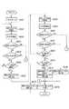
次に、実施例1において、給電装置100によって行われる異物検出処理について、図5のフローチャートを用いて説明する。異物検出処理は、CPU107がROM108に格納されているコンピュータプログラムを実行することにより実現することができる。図5に示す異物検出処理は、異物が給電装置100の近傍に存在するか否かを検出し、異物の有無に応じて、給電を制御するための処理を含む。
(Foreign matter detection processing)
Next, the foreign object detection process performed by thepower supply apparatus 100 in the first embodiment will be described with reference to the flowchart of FIG. The foreign object detection process can be realized by theCPU 107 executing a computer program stored in theROM 108. The foreign object detection process illustrated in FIG. 5 includes a process for detecting whether or not a foreign object exists in the vicinity of thepower supply apparatus 100 and controlling power supply according to the presence or absence of the foreign object.

なお、異物とは、NFC規格に対応する無線通信を行う手段及び給電装置100から供給される電力を受電するための手段の少なくとも一つを有していないデバイスである。また、異物は、給電装置100から供給される電力によって故障する可能性のあるデバイスであっても良いものとする。なお、異物は、例えば、金属やICカードのようなものであるものとする。また、異物は、給電装置100に対応していない装置であっても良いものとする。  Note that a foreign object is a device that does not have at least one of means for performing wireless communication corresponding to the NFC standard and means for receiving power supplied from thepower supply apparatus 100. Further, the foreign object may be a device that may break down due to electric power supplied from thepower supply apparatus 100. The foreign material is assumed to be, for example, a metal or an IC card. Further, the foreign object may be a device that does not correspond to thepower supply device 100.

給電装置100と電子機器200との距離が所定の範囲内に存在することがCPU107によって検出された場合に、電子機器200が給電の対象として選択されたとき、CPU107は、電子機器200に第2の電力を供給するように給電装置100を制御する。  When theCPU 107 detects that the distance between thepower supply apparatus 100 and theelectronic device 200 is within a predetermined range, when theelectronic device 200 is selected as a power supply target, theCPU 107 causes theelectronic device 200 to Thepower supply apparatus 100 is controlled so as to supply the electric power.

S501において、CPU107は、第2の電力を給電アンテナ106を介して電子機器200に供給するように発振器102、電力生成部103及び整合回路104を制御する。この場合、本フローチャートは、S502に進む。  In step S <b> 501, theCPU 107 controls theoscillator 102, thepower generation unit 103, and thematching circuit 104 so as to supply the second power to theelectronic device 200 via thepower supply antenna 106. In this case, the flowchart proceeds to S502.

S502において、CPU107は、可変コンデンサ301のキャパシタンスの値を設定値C1に設定し、可変コンデンサ302のキャパシタンスの値を設定値C2に設定する。さらに、CPU107は、可変コンデンサ301のキャパシタンスの値が設定値C1に設定され、かつ、可変コンデンサ302のキャパシタンスの値が設定値C2に設定された状態で、VSWRを算出する。さらに、CPU107は、現在、設定されている設定値C1、設定値C2及び取得したVSWRを関連付けてRAM109に記録する。この場合、本フローチャートは、S503に進む。なお、S502において、CPU107によって算出されるVSWRを「VSWR1」と呼ぶものとする。  In S502, theCPU 107 sets the value of the capacitance of the variable capacitor 301 to the set value C1, and sets the value of the capacitance of thevariable capacitor 302 to the set value C2. Further, theCPU 107 calculates VSWR in a state where the capacitance value of the variable capacitor 301 is set to the set value C1 and the capacitance value of thevariable capacitor 302 is set to the set value C2. Furthermore, theCPU 107 records the set value C1, the set value C2, and the acquired VSWR that are currently set in theRAM 109 in association with each other. In this case, the flowchart proceeds to S503. In S502, the VSWR calculated by theCPU 107 is referred to as “VSWR1”.

なお、設定値C1及び設定値C2は、あらかじめROM108に記録されている値であってもよい。また、設定値C1及び設定値C2は、給電装置100と電子機器200との距離が所定の範囲内に存在すると判定される前に、給電装置100の共振周波数fが、13.56MHzとなるように調整されたキャパシタンスの値であっても良いものとする。  Note that the setting value C1 and the setting value C2 may be values recorded in theROM 108 in advance. In addition, the set value C1 and the set value C2 are set so that the resonance frequency f of thepower supply apparatus 100 becomes 13.56 MHz before it is determined that the distance between thepower supply apparatus 100 and theelectronic device 200 is within a predetermined range. It may be a capacitance value adjusted to.

S503において、CPU107は、RAM109に記録されているVSWR1が所定値A以上であるか否かを判定する。所定値Aは、異物が給電装置100の近傍に存在するか否かを検出するための閾値である。例えば、所定値Aは、3〜4までの値である。CPU107によって、VSWR1が所定値A以上でないと判定された場合(S503でNo)、本フローチャートは、S503からS504に進む。CPU107によって、VSWR1が所定値A以上であると判定された場合(S503でYes)、CPU107は、異物を検出する。  In step S <b> 503, theCPU 107 determines whether VSWR <b> 1 recorded in theRAM 109 is greater than or equal to a predetermined value A. The predetermined value A is a threshold value for detecting whether or not a foreign object exists in the vicinity of thepower supply apparatus 100. For example, the predetermined value A is a value from 3 to 4. If theCPU 107 determines that VSWR1 is not equal to or greater than the predetermined value A (No in S503), the process proceeds from S503 to S504. When theCPU 107 determines that VSWR1 is equal to or greater than the predetermined value A (Yes in S503), theCPU 107 detects a foreign object.

給電装置100の近傍に異物が置かれた場合、VSWRは、急激に大きく変化する。この場合、給電装置100の近傍に異物が置かれた場合におけるVSWRの値は、給電装置100の近傍に給電装置100に対応する装置が置かれた場合におけるVSWRの値よりも大きくなる。そのため、給電装置100の近傍に給電装置100に対応する装置が置かれた場合におけるVSWRの値よりも大きい値になるように、所定値Aを設定することにより、CPU107は、VSWRと所定値Aとを比較することで、異物を検出することができる。この場合(S503でYes)、本フローチャートは、S503からS520に進む。  When a foreign object is placed in the vicinity of thepower supply apparatus 100, the VSWR changes greatly abruptly. In this case, the value of VSWR when a foreign object is placed in the vicinity ofpower supply apparatus 100 is larger than the value of VSWR when a device corresponding topower supply apparatus 100 is placed in the vicinity ofpower supply apparatus 100. Therefore, by setting the predetermined value A so that the value becomes larger than the value of VSWR when a device corresponding to thepower supply device 100 is placed in the vicinity of thepower supply device 100, theCPU 107 causes the VSWR and the predetermined value A to be set. Can be detected. In this case (Yes in S503), the flowchart proceeds from S503 to S520.

S504において、CPU107は、後述の調整処理を行う。調整処理は、VSWRが1となるように、可変コンデンサ301のキャパシタンスの値及び可変コンデンサ302のキャパシタンスの値を調整するための処理である。調整処理がCPU107によって行われた場合、CPU107は、可変コンデンサ301のキャパシタンスの値を調整するための設定値C3及び可変コンデンサ302キャパシタンスの値を調整するための設定値C4を取得する。この場合、本フローチャートは、S505に進む。  In step S504, theCPU 107 performs an adjustment process described later. The adjustment process is a process for adjusting the capacitance value of the variable capacitor 301 and the capacitance value of thevariable capacitor 302 so that VSWR becomes 1. When the adjustment process is performed by theCPU 107, theCPU 107 acquires a setting value C3 for adjusting the capacitance value of the variable capacitor 301 and a setting value C4 for adjusting the value of thevariable capacitor 302 capacitance. In this case, the flowchart proceeds to S505.

S505において、可変コンデンサ301のキャパシタンスの値を設定値C3に設定し、可変コンデンサ302のキャパシタンスの値を設定値C4に設定する。さらに、CPU107は、可変コンデンサ301のキャパシタンスの値が設定値C3に設定され、かつ、可変コンデンサ302のキャパシタンスの値が設定値C4に設定された状態で、VSWRを算出する。さらに、CPU107は、現在、設定されている設定値C3、設定値C4及び取得したVSWRを関連付けてRAM109に記録する。この場合、本フローチャートは、S506に進む。なお、S505において、CPU107によって算出されるVSWRを「VSWR2」と呼ぶものとする。なお、VSWR2は、VSWR1とは別にRAM109に記録されるものとする。  In S505, the value of the capacitance of the variable capacitor 301 is set to the set value C3, and the value of the capacitance of thevariable capacitor 302 is set to the set value C4. Further, theCPU 107 calculates VSWR with the capacitance value of the variable capacitor 301 set to the set value C3 and the capacitance value of thevariable capacitor 302 set to the set value C4. Further, theCPU 107 records the set value C3, the set value C4, and the acquired VSWR that are currently set in theRAM 109 in association with each other. In this case, the flowchart proceeds to S506. In step S505, the VSWR calculated by theCPU 107 is referred to as “VSWR2”. Note that VSWR2 is recorded in theRAM 109 separately from VSWR1.

S506において、CPU107は、RAM109に記録されているVSWR2が所定値A以上であるか否かを判定する。CPU107によって、VSWR2が所定値A以上でないと判定された場合(S506でNo)、本フローチャートは、S506からS507に進む。CPU107によって、VSWR2が所定値A以上であると判定された場合(S506でYes)、CPU107は、異物を検出する。この場合(S506でYes)、本フローチャートは、S506からS520に進む。  In step S506, theCPU 107 determines whether or not VSWR2 recorded in theRAM 109 is equal to or greater than a predetermined value A. When theCPU 107 determines that VSWR2 is not equal to or greater than the predetermined value A (No in S506), the process proceeds from S506 to S507. When theCPU 107 determines that VSWR2 is equal to or greater than the predetermined value A (Yes in S506), theCPU 107 detects a foreign object. In this case (Yes in S506), the flowchart proceeds from S506 to S520.

S507において、CPU107は、S502と同様に、可変コンデンサ301のキャパシタンスの値を設定値C1に設定し、可変コンデンサ302のキャパシタンスの値を設定値C2に設定し、VSWRを算出する。さらに、CPU107は、現在、設定されている設定値C1、設定値C2及び取得したVSWRを関連付けてRAM109に記録する。この場合、本フローチャートは、S508に進む。なお、S507において、CPU107によって算出されるVSWRを「VSWR3」と呼ぶものとする。なお、VSWR3は、VSWR1やVSWR2とは別にRAM109に記録されるものとする。  In S507, as in S502, theCPU 107 sets the capacitance value of the variable capacitor 301 to the set value C1, sets the capacitance value of thevariable capacitor 302 to the set value C2, and calculates VSWR. Furthermore, theCPU 107 records the set value C1, the set value C2, and the acquired VSWR that are currently set in theRAM 109 in association with each other. In this case, the flowchart proceeds to S508. In S507, the VSWR calculated by theCPU 107 is referred to as “VSWR3”. Note that VSWR3 is recorded in theRAM 109 separately from VSWR1 and VSWR2.

S508において、CPU107は、第1の電力を給電アンテナ106を介して電子機器200に供給するように電力生成部103を制御する。この場合、本フローチャートはS509に進む。  In step S <b> 508, theCPU 107 controls thepower generation unit 103 to supply the first power to theelectronic device 200 via thepower feeding antenna 106. In this case, the flowchart proceeds to S509.

S509において、CPU107は、電子機器200のステータスデータを取得するために、NFC規格に対応する無線通信を行うように変復調回路105を制御する。電子機器200のステータスデータが変復調回路105によって取得された場合、CPU107は、取得した電子機器200のステータスデータをRAM109に記録する。この場合、本フローチャートは、S510に進む。  In step S <b> 509, theCPU 107 controls the modulation /demodulation circuit 105 to perform wireless communication corresponding to the NFC standard in order to acquire the status data of theelectronic device 200. When the status data of theelectronic device 200 is acquired by the modulation /demodulation circuit 105, theCPU 107 records the acquired status data of theelectronic device 200 in theRAM 109. In this case, the flowchart proceeds to S510.

S510において、CPU107は、S509において取得された電子機器200のステータスデータを用いて、電子機器200のステータスが変更されたか否かを判定する。CPU107によって、電子機器200のステータスが変更されていないと判定された場合(S510でNo)、本フローチャートは、S510からS511に進む。CPU107によって、電子機器200のステータスが変更されたと判定された場合(S510でYes)、本フローチャートは、S510からS518に進む。  In S510, theCPU 107 determines whether the status of theelectronic device 200 has been changed using the status data of theelectronic device 200 acquired in S509. When theCPU 107 determines that the status of theelectronic device 200 has not been changed (No in S510), the process proceeds from S510 to S511. If theCPU 107 determines that the status of theelectronic device 200 has been changed (Yes in S510), the process proceeds from S510 to S518.

S511において、CPU107は、RAM109に記録されているVSWR3が所定値A以上であるか否かを判定する。CPU107によって、VSWR3が所定値A以上でないと判定された場合(S511でNo)、本フローチャートは、S511からS512に進む。CPU107によって、VSWR3が所定値A以上であると判定された場合(S511でYes)、CPU107は、異物を検出する。この場合(S511でYes)、本フローチャートは、S511からS520に進む。  In S511, theCPU 107 determines whether or not VSWR3 recorded in theRAM 109 is equal to or greater than a predetermined value A. If theCPU 107 determines that VSWR3 is not equal to or greater than the predetermined value A (No in S511), the process proceeds from S511 to S512. When theCPU 107 determines that VSWR3 is equal to or greater than the predetermined value A (Yes in S511), theCPU 107 detects a foreign object. In this case (Yes in S511), the flowchart proceeds from S511 to S520.

S512において、CPU107は、RAM109に記録されているVSWR1とVSWR3とを比較することによって、VSWR1とVSWR3との差分D1を算出する。さらに、CPU107は、差分D1が所定値B以上であるか否かを判定する。所定値Bは、所定値Bは、異物が給電装置100の近傍に存在するか否かを検出するための閾値である。CPU107によって、差分D1が所定値B以上でないと判定された場合(S512でNo)、本フローチャートは、S512からS513に進む。CPU107によって、差分D1が所定値B以上であると判定された場合(S512でYes)、CPU107は、異物を検出する。  In S512, theCPU 107 calculates a difference D1 between VSWR1 and VSWR3 by comparing VSWR1 and VSWR3 recorded in theRAM 109. Furthermore, theCPU 107 determines whether or not the difference D1 is greater than or equal to a predetermined value B. The predetermined value B is a threshold value for detecting whether or not a foreign object exists in the vicinity of thepower supply apparatus 100. When theCPU 107 determines that the difference D1 is not greater than or equal to the predetermined value B (No in S512), the process proceeds from S512 to S513. When theCPU 107 determines that the difference D1 is equal to or greater than the predetermined value B (Yes in S512), theCPU 107 detects a foreign object.

給電装置100の近傍に異物が置かれた場合、給電装置100の近傍に異物が置かれた場合におけるVSWRの変化量は、給電装置100の近傍に給電装置100に対応する装置が置かれた場合におけるVSWRの変化量よりも大きくなる。そのため、給電装置100の近傍に給電装置100に対応する装置が置かれた場合におけるVSWRの変化量よりも大きい値になるように所定値Bを設定することで、CPU107は、VSWRの変化量と所定値Bとを比較し、異物を検出することができる。この場合(S512でYes)、本フローチャートは、S512からS520に進む。  The amount of change in VSWR when a foreign object is placed in the vicinity of thepower supply apparatus 100 or a foreign object is placed in the vicinity of thepower supply apparatus 100 is the case where a device corresponding to thepower supply apparatus 100 is placed in the vicinity of thepower supply apparatus 100 It becomes larger than the amount of change in VSWR. Therefore, by setting the predetermined value B to be a value larger than the amount of change in VSWR when a device corresponding to thepower supply device 100 is placed in the vicinity of thepower supply device 100, theCPU 107 determines the amount of change in VSWR as The foreign object can be detected by comparing with the predetermined value B. In this case (Yes in S512), the flowchart proceeds from S512 to S520.

S513において、CPU107は、S505と同様に、可変コンデンサ301のキャパシタンスの値を設定値C3に設定し、可変コンデンサ302のキャパシタンスの値を設定値C4に設定し、VSWRを算出する。さらに、CPU107は、現在、設定されている設定値C3、設定値C4及び取得したVSWRを関連付けてRAM109に記録する。この場合、本フローチャートは、S514に進む。なお、S513において、CPU107によって算出されるVSWRを「VSWR4」と呼ぶものとする。なお、VSWR4は、VSWR1、VSWR2やVSWR4とは別にRAM109に記録されるものとする。  In S513, as in S505, theCPU 107 sets the value of the capacitance of the variable capacitor 301 to the set value C3, sets the value of the capacitance of thevariable capacitor 302 to the set value C4, and calculates VSWR. Further, theCPU 107 records the set value C3, the set value C4, and the acquired VSWR that are currently set in theRAM 109 in association with each other. In this case, the flowchart proceeds to S514. In S513, the VSWR calculated by theCPU 107 is referred to as “VSWR4”. Note that VSWR4 is recorded in theRAM 109 separately from VSWR1, VSWR2, and VSWR4.

S514において、CPU107は、S509において取得された電子機器200のステータスデータを用いて、電子機器200のステータスが変更されたか否かを判定する。CPU107によって、電子機器200のステータスが変更されていないと判定された場合(S514でNo)、本フローチャートは、S514からS515に進む。CPU107によって、電子機器200のステータスが変更されたと判定された場合(S514でYes)、本フローチャートは、S514からS519に進む。  In step S514, theCPU 107 determines whether the status of theelectronic device 200 has been changed using the status data of theelectronic device 200 acquired in step S509. If theCPU 107 determines that the status of theelectronic device 200 has not been changed (No in S514), the flowchart proceeds from S514 to S515. If theCPU 107 determines that the status of theelectronic device 200 has been changed (Yes in S514), the process proceeds from S514 to S519.

S515において、CPU107は、RAM109に記録されているVSWR4が所定値A以上であるか否かを判定する。CPU107によって、VSWR4が所定値A以上でないと判定された場合(S515でNo)、本フローチャートは、S515からS516に進む。CPU107によって、VSWR4が所定値A以上であると判定された場合(S515でYes)、CPU107は、異物を検出する。この場合(S515でYes)、本フローチャートは、S515からS520に進む。  In S515, theCPU 107 determines whether or not VSWR4 recorded in theRAM 109 is equal to or greater than a predetermined value A. When theCPU 107 determines that VSWR4 is not equal to or greater than the predetermined value A (No in S515), the flowchart proceeds from S515 to S516. When theCPU 107 determines that the VSWR 4 is equal to or greater than the predetermined value A (Yes in S515), theCPU 107 detects a foreign object. In this case (Yes in S515), the flowchart proceeds from S515 to S520.

S516において、CPU107は、RAM109に記録されているVSWR2とVSWR4とを比較することによって、VSWR2とVSWR4との差分D2を算出する。さらに、CPU107は、差分D2が所定値B以上であるか否かを判定する。CPU107によって、差分D2が所定値B以上でないと判定された場合(S516でNo)、本フローチャートは、S516からS517に進む。CPU107によって、差分D2が所定値B以上であると判定された場合(S516でYes)、本フローチャートは、S516からS520に進む。  In S516, theCPU 107 calculates a difference D2 between VSWR2 and VSWR4 by comparing VSWR2 and VSWR4 recorded in theRAM 109. Furthermore, theCPU 107 determines whether or not the difference D2 is greater than or equal to a predetermined value B. When theCPU 107 determines that the difference D2 is not equal to or greater than the predetermined value B (No in S516), the flowchart proceeds from S516 to S517. When theCPU 107 determines that the difference D2 is equal to or greater than the predetermined value B (Yes in S516), the flowchart proceeds from S516 to S520.

S517において、CPU107は、電子機器200に対する給電を停止するか否かを判定する。CPU107によって、電子機器200に対する給電を停止すると判定された場合(S517でYes)、本フローチャートは、S517からS521に進む。  In step S517, theCPU 107 determines whether to stop power supply to theelectronic device 200. When it is determined by theCPU 107 that power supply to theelectronic device 200 is stopped (Yes in S517), the process proceeds from S517 to S521.

CPU107によって、電子機器200に対する給電を停止しないと判定された場合(S517でNo)、本フローチャートは、S521からS501に戻る。この場合、CPU107は、再び、第2の電力を電子機器200に供給するように給電装置100を制御する。  When theCPU 107 determines that power supply to theelectronic device 200 is not stopped (No in S517), the flowchart returns from S521 to S501. In this case, theCPU 107 controls thepower supply apparatus 100 so as to supply the second power to theelectronic device 200 again.

電子機器200のステータスが変更されたと判定された場合(S510でYes)、S518において、CPU107は、電子機器200のステータスの変化に応じて、VSWR3を補正する。  When it is determined that the status of theelectronic device 200 has been changed (Yes in S510), in S518, theCPU 107 corrects theVSWR 3 in accordance with the change in the status of theelectronic device 200.

これは、電子機器200の動作モードや負荷の状態が変化した場合、または、電子機器200の移動距離が特定の距離以上である場合、電子機器200のステータスの変化に伴い、VSWRが変化する場合があるからである。この場合、CPU107は、異物が給電装置100の近傍に存在しない場合であっても、電子機器200のステータスの変化によるVSWRの変化を、異物が給電装置100の近傍に置かれたことによるVSWRの変化であると誤検出してしまう場合があった。  This is because when the operation mode or load state of theelectronic device 200 changes, or when the movement distance of theelectronic device 200 is greater than or equal to a specific distance, the VSWR changes as the status of theelectronic device 200 changes. Because there is. In this case, even if the foreign object does not exist in the vicinity of thepower supply apparatus 100, theCPU 107 changes the VSWR due to the change in the status of theelectronic device 200 and changes the VSWR due to the foreign object being placed in the vicinity of thepower supply apparatus 100. In some cases, it was erroneously detected as a change.

このような誤検出を防ぐため、CPU107は、ROM108に記録されている補正テーブルと、電子機器200から取得された電子機器200のステータスデータとを用いて、補正値を検出し、検出された補正値に応じて、VSWR3を補正する。さらに、CPU107は、RAM109に記録されているVSWR3が補正されたVSWR3に上書きされるようにする。この場合、本フローチャートは、S511に進む。  In order to prevent such erroneous detection, theCPU 107 detects a correction value by using the correction table recorded in theROM 108 and the status data of theelectronic device 200 acquired from theelectronic device 200, and detects the detected correction. VSWR3 is corrected according to the value. Furthermore, theCPU 107 causes theVSWR 3 recorded in theRAM 109 to be overwritten on the correctedVSWR 3. In this case, the flowchart proceeds to S511.

電子機器200のステータスが変更されたと判定された場合(S514でYes)、S519において、CPU107は、電子機器200のステータスの変化に応じて、VSWR4を補正する。CPU107は、ROM108に記録されている補正テーブルと、電子機器200から取得された電子機器200のステータスデータとを用いて、補正値を検出し、検出された補正値に応じて、VSWR4を補正する。さらに、CPU107は、RAM109に記録されているVSWR4が補正されたVSWR4に上書きされるようにする。この場合、本フローチャートは、S515に進む。  When it is determined that the status of theelectronic device 200 has been changed (Yes in S514), in S519, theCPU 107 corrects the VSWR 4 according to the change in the status of theelectronic device 200. TheCPU 107 detects a correction value using the correction table recorded in theROM 108 and the status data of theelectronic device 200 acquired from theelectronic device 200, and corrects the VSWR 4 according to the detected correction value. . Furthermore, theCPU 107 causes the VSWR 4 recorded in theRAM 109 to be overwritten on the corrected VSWR 4. In this case, the flowchart proceeds to S515.

S520において、CPU107は、異物が検出されたことを通知するための警告データを表示するように表示部110を制御する。この場合、本フローチャートは、S521に進む。  In step S520, theCPU 107 controls thedisplay unit 110 to display warning data for notifying that a foreign object has been detected. In this case, the flowchart proceeds to S521.

S521において、CPU107は、給電アンテナ106を介して外部に出力している電力を制限するようにするために発振器102、電力生成部103及び整合回路104の少なくとも一つを制御する。  In step S <b> 521, theCPU 107 controls at least one of theoscillator 102, thepower generation unit 103, and thematching circuit 104 in order to limit the power output to the outside via thepower supply antenna 106.

例えば、給電アンテナ106を介して、外部に第1の電力が出力されている場合、CPU107は、第1の電力の出力を停止するように制御する。また、給電アンテナ106を介して、外部に第2の電力が出力されている場合、CPU107は、第2の電力の出力を停止するように制御する。  For example, when the first power is output to the outside via thepower supply antenna 106, theCPU 107 controls to stop the output of the first power. In addition, when the second power is output to the outside via thepower supply antenna 106, theCPU 107 controls to stop the output of the second power.

また、例えば、給電アンテナ106を介して、外部に第1の電力が出力されている場合、CPU107は、第1の電力の値が徐々に小さくなるように制御してもよい。また、給電アンテナ106を介して、外部に第2の電力が出力されている場合、CPU107は、第2の電力から第1の電力を出力するように制御してから第1の電力の出力を停止するように制御してもよい。  Further, for example, when the first power is output to the outside via thepower feeding antenna 106, theCPU 107 may perform control so that the value of the first power gradually decreases. In addition, when the second power is output to the outside via thepower feeding antenna 106, theCPU 107 performs control so that the first power is output from the second power, and then outputs the first power. You may control to stop.

この場合、本フローチャートは終了する。なお、CPU107は、給電を停止する前に、給電を停止することを電子機器200やユーザに通知するようにしてもよい。  In this case, this flowchart ends. Note that theCPU 107 may notify theelectronic device 200 or the user that the power supply is stopped before the power supply is stopped.

なお、所定値A及び所定値Bは、あらかじめROM108に記録されているものであっても、電子機器200から取得されたデータに応じてCPU107によって設定されるものであってもよいものとする。  Note that the predetermined value A and the predetermined value B may be recorded in theROM 108 in advance or may be set by theCPU 107 according to data acquired from theelectronic device 200.

また、S502からS507までの処理は、給電装置100が第2の電力を出力している場合に、CPU107によって行われるようにしたが、これに限られないものとする。例えば、S502からS507までの処理は、給電装置100が第1の電力を出力している場合に、CPU107によって行われてもよいものとする。  Further, the processing from S502 to S507 is performed by theCPU 107 when thepower supply apparatus 100 outputs the second power, but is not limited thereto. For example, the processing from S502 to S507 may be performed by theCPU 107 when thepower supply apparatus 100 outputs the first power.

(調整処理)
次に、実施例1において、S504において給電装置100によって行われる調整処理について、図6のフローチャートを用いて説明する。調整処理は、CPU107がROM108に格納されているコンピュータプログラムを実行することにより実現することができる。
(Adjustment process)
Next, the adjustment process performed by thepower supply apparatus 100 in S504 in the first embodiment will be described with reference to the flowchart of FIG. The adjustment process can be realized by theCPU 107 executing a computer program stored in theROM 108.

S601において、CPU107は、RAM109に記録されている第1の回数T1、第2の回数T2及び第3の回数T3の値をリセットするように制御する。この場合、本フローチャートは、S602に進む。なお、第1の回数T1、第2の回数T2及び第3の回数T3は、カウンタ107aによってカウントされる値であり、第1の回数T1、第2の回数T2及び第3の回数T3については後述する。  In step S601, theCPU 107 controls to reset the values of the first number of times T1, the second number of times T2, and the third number of times T3 recorded in theRAM 109. In this case, the flowchart proceeds to S602. The first number of times T1, the second number of times T2, and the third number of times T3 are values counted by thecounter 107a. Regarding the first number of times T1, the second number of times T2, and the third number of times T3, It will be described later.

給電装置100の近傍に電子機器200が存在する場合、整合回路104のインダクタンスLやCPU107によって算出されるVSWRが電子機器200から影響を受ける場合があった。このような場合において、給電装置100が電子機器200に給電する場合、給電装置100は、電力の損失を減少させ、効率よく電力の伝送を行うようにする必要がある。電力の伝送を効率良く行うためには、VSWRが1になることが望ましい。このため、CPU107は、整合回路104に含まれる可変コンデンサ301及び可変コンデンサ302の少なくとも一つを制御し、反射電力検出回路112によって検出されるVSWRが1になるように調整する。  When theelectronic device 200 exists in the vicinity of thepower supply apparatus 100, the inductance L of thematching circuit 104 and the VSWR calculated by theCPU 107 may be affected by theelectronic device 200. In such a case, when thepower supply apparatus 100 supplies power to theelectronic device 200, thepower supply apparatus 100 needs to reduce power loss and efficiently transmit power. In order to efficiently transmit power, it is desirable that VSWR is 1. Therefore, theCPU 107 controls at least one of the variable capacitor 301 and thevariable capacitor 302 included in thematching circuit 104 and adjusts so that the VSWR detected by the reflectedpower detection circuit 112 becomes 1.

S602において、CPU107は、共振周波数fが13.56MHzになるようにしながら、VSWRの値が1以上になるように可変コンデンサ301のキャパシタンスの値を変更するようにする。さらに、CPU107は、変更された可変コンデンサ301のキャパシタンスの値をRAM109に記録する。CPU107は、第1の回数T1に1を加算するようにカウンタ107aを制御する。なお、第1の回数T1は、可変コンデンサ301のキャパシタンスの値が変更された回数を示す。この場合、本フローチャートはS603に進む。  In S602, theCPU 107 changes the capacitance value of the variable capacitor 301 so that the value of VSWR becomes 1 or more while the resonance frequency f is 13.56 MHz. Further, theCPU 107 records the changed value of the capacitance of the variable capacitor 301 in theRAM 109. TheCPU 107 controls thecounter 107a so as to add 1 to the first number of times T1. The first number of times T1 indicates the number of times the capacitance value of the variable capacitor 301 has been changed. In this case, the flowchart proceeds to S603.

S603において、CPU107は、VSWRを算出し、S602において変更された可変コンデンサ301のキャパシタンスの値と算出されたVSWRとを関連付けてRAM109に記録する。この場合、本フローチャートは、S604に進む。なお、S603において、CPU107によって算出されるVSWRを「VSWR5」と呼ぶものとする。なお、VSWR5は、VSWR1、VSWR2、VSWR3やVSWR4とは別にRAM109に記録されるものとする。  In S603, theCPU 107 calculates VSWR, and records the value of the capacitance of the variable capacitor 301 changed in S602 in association with the calculated VSWR in theRAM 109. In this case, the flowchart proceeds to S604. In S603, the VSWR calculated by theCPU 107 is referred to as “VSWR5”. Note that VSWR5 is recorded in theRAM 109 separately from VSWR1, VSWR2, VSWR3, and VSWR4.

S604において、CPU107は、RAM109に記録されているVSWR5が所定値C以下であり、かつ、1以上であるか否かを判定する。所定値Cは、VSWRに対応する閾値である。例えば、所定値Cは、1.1〜1.3までの値である。CPU107によって、VSWR5が、所定値C以下であり、かつ、1以上であると判定された場合(S604でYes)、本フローチャートは、S604からS615に進む。  In S604, theCPU 107 determines whether or not VSWR5 recorded in theRAM 109 is equal to or less than a predetermined value C and equal to or greater than 1. The predetermined value C is a threshold value corresponding to VSWR. For example, the predetermined value C is a value from 1.1 to 1.3. When theCPU 107 determines that VSWR5 is equal to or less than the predetermined value C and is equal to or greater than 1 (Yes in S604), the process proceeds from S604 to S615.

CPU107によって、VSWR5が、所定値Cよりも大きいと判定された場合(S604でNo)、本フローチャートは、S604からS605に進む。CPU107によって、VSWR5が、1よりも小さいと判定された場合(S604でNo)、本フローチャートは、S604からS605に進む。  When theCPU 107 determines that VSWR5 is larger than the predetermined value C (No in S604), the process proceeds from S604 to S605. When theCPU 107 determines that VSWR5 is smaller than 1 (No in S604), the process proceeds from S604 to S605.

S605において、CPU107は、RAM109に記録されているVSWR5が所定値D以上であるか否かを判定する。所定値Dは、VSWRに対応する閾値である。例えば、所定値Dは、2〜2.5までの値である。CPU107によって、VSWR5が所定値D以上でないと判定された場合(S605でNo)、本フローチャートは、S605からS607に進む。CPU107によって、VSWR5が所定値D以上であると判定された場合(S605でYes)、本フローチャートは、S605からS606に進む。  In step S <b> 605, theCPU 107 determines whether or not the VSWR 5 recorded in theRAM 109 is greater than or equal to a predetermined value D. The predetermined value D is a threshold value corresponding to VSWR. For example, the predetermined value D is a value from 2 to 2.5. When theCPU 107 determines that VSWR5 is not equal to or greater than the predetermined value D (No in S605), the process proceeds from S605 to S607. When theCPU 107 determines that VSWR5 is equal to or greater than the predetermined value D (Yes in S605), the process proceeds from S605 to S606.

S606において、CPU107は、RAM109に記録されている第1の回数T1が所定の回数E以上であるか否かを判定する。所定の回数Eは、第1の回数T1に対応する閾値である。例えば、所定の回数Eは、1以上の値であればどのような値であっても良いものとする。CPU107によって、第1の回数T1が所定の回数E以上であると判定された場合(S606でYes)、本フローチャートは、S606からS607に進む。CPU107によって、第1の回数T1が所定の回数E以上でないと判定された場合(S606でNo)、本フローチャートは、S606からS602に戻る。  In step S <b> 606, theCPU 107 determines whether or not the first number of times T <b> 1 recorded in theRAM 109 is equal to or greater than the predetermined number of times E. The predetermined number E is a threshold value corresponding to the first number T1. For example, the predetermined number of times E may be any value as long as the value is 1 or more. If theCPU 107 determines that the first number of times T1 is equal to or greater than the predetermined number of times E (Yes in S606), the process proceeds from S606 to S607. When theCPU 107 determines that the first number of times T1 is not equal to or greater than the predetermined number of times E (No in S606), the flowchart returns from S606 to S602.

S607において、CPU107は、変更された可変コンデンサ301のキャパシタンスの値の中で算出されたVSWRが最も1に近くなるように、可変コンデンサ301のキャパシタンスの値を設定する。この場合、本フローチャートはS608に進む。  In step S <b> 607, theCPU 107 sets the capacitance value of the variable capacitor 301 so that the calculated VSWR is closest to 1 among the changed capacitance values of the variable capacitor 301. In this case, the flowchart proceeds to S608.

S608において、CPU107は、共振周波数fが13.56MHzになるようにしながら、VSWRの値が1以上になるように可変コンデンサ302のキャパシタンスの値を変更するようにする。さらに、CPU107は、変更された可変コンデンサ302のキャパシタンスの値をRAM109に記録する。CPU107は、第2の回数T2に1を加算するようにカウンタ107aを制御する。なお、第2の回数T2は、可変コンデンサ302のキャパシタンスの値が変更された回数を示す。この場合、本フローチャートはS609に進む。  In step S <b> 608, theCPU 107 changes the capacitance value of thevariable capacitor 302 so that the value of VSWR becomes 1 or more while the resonance frequency f is 13.56 MHz. Further, theCPU 107 records the changed capacitance value of thevariable capacitor 302 in theRAM 109. TheCPU 107 controls thecounter 107a so as to add 1 to the second number of times T2. Note that the second number of times T2 indicates the number of times the capacitance value of thevariable capacitor 302 has been changed. In this case, the flowchart proceeds to S609.

S609において、CPU107は、VSWRを算出し、S608において変更された可変コンデンサ302のキャパシタンスの値と算出されたVSWRとを関連付けてRAM109に記録する。この場合、本フローチャートは、S610に進む。なお、S609において、CPU107によって算出されるVSWRを「VSWR6」と呼ぶものとする。なお、VSWR6は、VSWR1、VSWR2、VSWR3、VSWR4やVSWR5とは別にRAM109に記録されるものとする。  In S609, theCPU 107 calculates VSWR, and records the value of the capacitance of thevariable capacitor 302 changed in S608 in association with the calculated VSWR in theRAM 109. In this case, the flowchart proceeds to S610. In S609, the VSWR calculated by theCPU 107 is referred to as “VSWR6”. Note that VSWR6 is recorded in theRAM 109 separately from VSWR1, VSWR2, VSWR3, VSWR4, and VSWR5.

S610において、CPU107は、RAM109に記録されているVSWR6が所定値C以下であり、かつ、1以上であるか否かを判定する。CPU107によって、VSWR6が、所定値C以下であり、かつ、1以上であると判定された場合(S610でYes)、本フローチャートは、S610からS615に進む。CPU107によって、VSWR6が、所定値Cよりも大きいと判定された場合(S610でNo)、本フローチャートは、S610からS611に進む。CPU107によって、VSWR6が、1よりも小さいと判定された場合(S610でNo)、本フローチャートは、S610からS611に進む。  In step S610, theCPU 107 determines whether the VSWR 6 recorded in theRAM 109 is equal to or less than a predetermined value C and equal to or greater than 1. When theCPU 107 determines that the VSWR 6 is equal to or less than the predetermined value C and equal to or greater than 1 (Yes in S610), the process proceeds from S610 to S615. When theCPU 107 determines that VSWR6 is greater than the predetermined value C (No in S610), the process proceeds from S610 to S611. When theCPU 107 determines that VSWR6 is smaller than 1 (No in S610), the flowchart proceeds from S610 to S611.

S611において、CPU107は、RAM109に記録されているVSWR6が所定値F以上であるか否かを判定する。所定値Fは、VSWRに対応する閾値である。例えば、所定値Fは、1.3〜1.5までの値である。CPU107によって、VSWR6が所定値F以上でないと判定された場合(S611でNo)、本フローチャートは、S611からS616に進む。CPU107によって、VSWR6が所定値F以上であると判定された場合(S611でYes)、本フローチャートは、S611からS612に進む。  In step S611, theCPU 107 determines whether or not the VSWR 6 recorded in theRAM 109 is equal to or greater than a predetermined value F. The predetermined value F is a threshold value corresponding to VSWR. For example, the predetermined value F is a value from 1.3 to 1.5. When theCPU 107 determines that the VSWR 6 is not equal to or greater than the predetermined value F (No in S611), the flowchart proceeds from S611 to S616. When theCPU 107 determines that the VSWR 6 is equal to or greater than the predetermined value F (Yes in S611), the flowchart proceeds from S611 to S612.

S612において、CPU107は、RAM109に記録されている第2の回数T2が所定の回数G以上であるか否かを判定する。所定の回数Gは、第2の回数T2に対応する閾値である。例えば、所定の回数Gは、1以上の値であればどのような値であっても良いものとする。CPU107によって、第2の回数T2が所定の回数G以上でないと判定された場合(S612でNo)、本フローチャートは、S612からS608に戻る。CPU107によって、第2の回数T2が所定の回数G以上であると判定された場合(S612でYes)、CPU107は、第3の回数T3に1を加算するようにカウンタ107aを制御する。なお、第3の回数T3は、S602〜S612までの処理が行われた回数を示す。CPU107によって、第2の回数T2が所定の回数G以上であると判定された場合(S612でYes)、本フローチャートは、S612からS613に進む。  In S612, theCPU 107 determines whether or not the second number of times T2 recorded in theRAM 109 is equal to or greater than the predetermined number of times G. The predetermined number of times G is a threshold value corresponding to the second number of times T2. For example, the predetermined number of times G may be any value as long as the value is 1 or more. When theCPU 107 determines that the second number of times T2 is not equal to or greater than the predetermined number of times G (No in S612), the process returns from S612 to S608. When theCPU 107 determines that the second number of times T2 is equal to or greater than the predetermined number of times G (Yes in S612), theCPU 107 controls thecounter 107a to add 1 to the third number of times T3. The third number of times T3 indicates the number of times that the processing from S602 to S612 has been performed. When theCPU 107 determines that the second number of times T2 is equal to or greater than the predetermined number of times G (Yes in S612), the flowchart proceeds from S612 to S613.

S613において、CPU107は、RAM109に記録されている第3の回数T3が所定の回数H以上であるか否かを判定する。所定の回数Hは、第3の回数T3に対応する閾値である。例えば、所定の回数Hは、1以上の値であればどのような値であっても良いものとする。CPU107によって、第3の回数T3が所定の回数H以上であると判定された場合(S613でYes)、本フローチャートは、S613からS614に進む。CPU107によって、第3の回数T3が所定の回数H以上でないと判定された場合(S613でNo)、本フローチャートは、S613からS617に進む。  In step S613, theCPU 107 determines whether or not the third number T3 recorded in theRAM 109 is equal to or greater than the predetermined number H. The predetermined number of times H is a threshold value corresponding to the third number of times T3. For example, the predetermined number of times H may be any value as long as the value is 1 or more. If theCPU 107 determines that the third number T3 is equal to or greater than the predetermined number H (Yes in S613), the process proceeds from S613 to S614. When theCPU 107 determines that the third number T3 is not equal to or greater than the predetermined number H (No in S613), the process proceeds from S613 to S617.

S614において、CPU107は、変更された可変コンデンサ301のキャパシタンスの値と変更された可変コンデンサ302のキャパシタンスの値との組み合わせの中で、算出されたVSWRが最も1に近くなるようなキャパシタンスの組み合わせを設定する。この場合、CPU107は、算出されたVSWRが最も1に近くなるように、可変コンデンサ301のキャパシタンスの値及び可変コンデンサ302のキャパシタンスの値を設定する。この場合、本フローチャートはS615に進む。  In step S <b> 614, theCPU 107 selects a combination of capacitances such that the calculated VSWR is closest to 1 among combinations of the changed capacitance value of the variable capacitor 301 and the changed capacitance value of thevariable capacitor 302. Set. In this case, theCPU 107 sets the capacitance value of the variable capacitor 301 and the capacitance value of thevariable capacitor 302 so that the calculated VSWR is closest to 1. In this case, the flowchart proceeds to S615.

S615において、CPU107は、現在、設定されている可変コンデンサ301のキャパシタンスの値を設定値C3としてRAM109に記録する。さらに、CPU107は、現在、設定されている可変コンデンサ302のキャパシタンスの値を設定値C4としてRAM109に記録する。この場合、本フローチャートは終了する。なお、このことによって、CPU107は、設定値C3及び設定値C4を取得することができる。  In S615, theCPU 107 records the currently set capacitance value of the variable capacitor 301 in theRAM 109 as the set value C3. Further, theCPU 107 records the currently set value of the capacitance of thevariable capacitor 302 in theRAM 109 as the set value C4. In this case, this flowchart ends. As a result, theCPU 107 can acquire the set value C3 and the set value C4.

S616において、CPU107は、変更された可変コンデンサ302のキャパシタンスの値の中で、算出されたVSWRが最も1に近くなるように可変コンデンサ302のキャパシタンスの値を設定する。この場合、本フローチャートはS615に進む。  In step S <b> 616, theCPU 107 sets the capacitance value of thevariable capacitor 302 so that the calculated VSWR is closest to 1 among the changed capacitance values of thevariable capacitor 302. In this case, the flowchart proceeds to S615.

S617において、CPU107は、S616と同様に、変更された可変コンデンサ302のキャパシタンスの値の中で、算出されたVSWRが最も1に近くなるように可変コンデンサ302のキャパシタンスの値を設定する。この場合、本フローチャートはS602に戻る。  In S617, as in S616, theCPU 107 sets the capacitance value of thevariable capacitor 302 so that the calculated VSWR is closest to 1 among the changed capacitance values of thevariable capacitor 302. In this case, the flowchart returns to S602.

このように、実施例1に係る給電装置100は、外部に出力する電力の反射に関するVSWRを用いて異物の検出を行うようにした。このため、給電装置100は、電力を電子機器200に供給している場合に異物が給電装置100の近傍に置かれた場合であっても、異物の存在を検出することができる。  As described above, thepower supply apparatus 100 according to the first embodiment detects a foreign object using the VSWR related to the reflection of the power output to the outside. For this reason, thepower supply apparatus 100 can detect the presence of a foreign object even when the foreign object is placed in the vicinity of thepower supply apparatus 100 when power is supplied to theelectronic device 200.

また、給電装置100は、VSWRの値及びVSWRの変化量に応じて、異物の検出を行うようにしたので、電子機器200のステータスの変化に伴うVSWRの変化を異物の影響によるVSWRの変化として誤検出しないようにすることができる。  In addition, since thepower supply apparatus 100 detects foreign matter according to the value of VSWR and the amount of change in VSWR, the change in VSWR accompanying the change in status of theelectronic device 200 is regarded as the change in VSWR due to the influence of the foreign matter. It is possible to prevent false detection.

さらに、給電装置100は、異物を検出した場合、電子機器200への電力の供給を制限するようにするので、異物に電力を供給しないようにしながら、電子機器200に対して安全に電力を供給するようにすることができる。このため、給電装置100によって検出された異物が金属である場合、金属を給電装置100からの給電によって発熱させないようにすることができる。また、給電装置100によって検出された異物がICカードのようなデバイスである場合、ICカードを給電装置100からの給電によって故障させないようにすることができる。  Furthermore, thepower supply apparatus 100 restricts the supply of power to theelectronic device 200 when a foreign object is detected. Therefore, thepower supply apparatus 100 supplies power safely to theelectronic device 200 without supplying power to the foreign object. To be able to. For this reason, when the foreign material detected by thepower supply apparatus 100 is a metal, it is possible to prevent the metal from being heated by the power supply from thepower supply apparatus 100. When the foreign matter detected by thepower supply apparatus 100 is a device such as an IC card, the IC card can be prevented from being damaged by power supply from thepower supply apparatus 100.

したがって、給電装置100は、異物の有無に応じて、適切な給電を行うようにすることができる。  Therefore, thepower supply apparatus 100 can perform appropriate power supply according to the presence or absence of foreign matter.

なお、給電装置100は、VSWRを用いて異物を検出するようにしたが、SWRを用いて異物を検出するようにしても良いものとする。  Note that thepower supply apparatus 100 detects foreign objects using VSWR, but may detect foreign objects using SWR.

[実施例2]
以下、本発明に係る実施例2について、説明を行う。なお、実施例2が実施例1と同様な構成を有する場合や、実施例1と同様な処理及び動作を行う場合、共通する説明を省略する。
[Example 2]
Hereinafter, Example 2 according to the present invention will be described. In addition, when Example 2 has the same configuration as that of Example 1 or when processing and operations similar to Example 1 are performed, common description is omitted.

(調整処理)
次に、実施例2において、CPU107によって図5の異物検出処理のS504において給電装置100によって行われる調整処理について、図7のフローチャートを用いて説明する。図7の調整処理は、CPU107がROM108に格納されているコンピュータプログラムを実行することにより実現することができる。
(Adjustment process)
Next, the adjustment process performed by thepower supply apparatus 100 in step S504 of the foreign object detection process of FIG. 5 by theCPU 107 in the second embodiment will be described with reference to the flowchart of FIG. The adjustment process in FIG. 7 can be realized by theCPU 107 executing a computer program stored in theROM 108.

なお、実施例1において説明された調整処理と同様である処理の説明を省略し、異なる処理について説明を行う。  In addition, description of the process similar to the adjustment process demonstrated in Example 1 is abbreviate | omitted, and a different process is demonstrated.

なお、図7のS701〜S703、S706〜S708、S711及びS712は、図6のS602〜S604、S608〜S610、S614及びS615と共通する処理を行うため、説明を省略する。  7 are the same as S602 to S604, S608 to S610, S614, and S615 of FIG. 6, and thus description thereof is omitted.

S704において、CPU107は、RAM109に記録されているVSWR5が所定値D以上であるか否かを判定する。所定値Dは、VSWRに対応する閾値である。CPU107によって、VSWR5が所定値D以上でないと判定された場合(S704でNo)、本フローチャートは、S704からS706に進む。CPU107によって、VSWR5が所定値D以上であると判定された場合(S704でYes)、本フローチャートは、S704からS705に進む。  In step S <b> 704, theCPU 107 determines whether the VSWR 5 recorded in theRAM 109 is equal to or greater than a predetermined value D. The predetermined value D is a threshold value corresponding to VSWR. If theCPU 107 determines that VSWR5 is not equal to or greater than the predetermined value D (No in S704), the process proceeds from S704 to S706. When theCPU 107 determines that VSWR5 is equal to or greater than the predetermined value D (Yes in S704), the process proceeds from S704 to S705.

S705において、CPU107は、可変コンデンサ301のキャパシタンスの値の変更を全てのパターン行ったか否かを判定する。CPU107によって、可変コンデンサ301のキャパシタンスの値の変更を全てのパターン行っていないと判定された場合(S705でNo)、本フローチャートは、S705からS701に戻る。CPU107によって、可変コンデンサ301のキャパシタンスの値の変更を全てのパターン行ったと判定された場合(S705でYes)、本フローチャートは、S705からS706に進む。  In step S <b> 705, theCPU 107 determines whether all patterns of changing the capacitance value of the variable capacitor 301 have been performed. If it is determined by theCPU 107 that the capacitance value of the variable capacitor 301 has not been changed in all patterns (No in S705), the process returns from S705 to S701. If theCPU 107 determines that all the patterns of changing the capacitance value of the variable capacitor 301 have been performed (Yes in S705), the process proceeds from S705 to S706.

S709において、CPU107は、RAM109に記録されているVSWR6が所定値F以上であるか否かを判定する。CPU107によって、VSWR6が所定値F以上でないと判定された場合(S709でNo)、本フローチャートは、S709からS711に進む。CPU107によって、VSWR6が所定値F以上であると判定された場合(S709でYes)、本フローチャートは、S709からS710に進む。  In step S709, theCPU 107 determines whether the VSWR 6 recorded in theRAM 109 is equal to or greater than a predetermined value F. When theCPU 107 determines that the VSWR 6 is not equal to or greater than the predetermined value F (No in S709), the flowchart proceeds from S709 to S711. If theCPU 107 determines that VSWR6 is equal to or greater than the predetermined value F (Yes in S709), the process proceeds from S709 to S710.

S710において、CPU107は、可変コンデンサ302のキャパシタンスの値の変更を全てのパターン行ったか否かを判定する。CPU107によって、可変コンデンサ302のキャパシタンスの値の変更を全てのパターン行っていないと判定された場合(S710でNo)、本フローチャートは、S710からS706に戻る。CPU107によって、可変コンデンサ302のキャパシタンス値の変更を全てのパターン行ったと判定された場合(S710でYes)、本フローチャートは、S710からS711に進む。  In step S <b> 710, theCPU 107 determines whether all patterns of changing the capacitance value of thevariable capacitor 302 have been performed. When it is determined by theCPU 107 that the capacitance value of thevariable capacitor 302 has not been changed in all patterns (No in S710), the flowchart returns from S710 to S706. If theCPU 107 determines that all patterns of changing the capacitance value of thevariable capacitor 302 have been performed (Yes in S710), the process proceeds from S710 to S711.

なお、実施例2において、給電装置100が実施例1と共通する処理を行う場合においては、実施例1と同様な効果が得られるものとする。  In the second embodiment, when thepower supply apparatus 100 performs a process common to the first embodiment, the same effect as that of the first embodiment is obtained.

実施例2に係る給電装置100は、可変コンデンサ301のキャパシタンスの値を全パターン変更し、全パターンのキャパシタンスの値に対応するVSWRを用いて、設定値C3を取得するようにした。さらに、給電装置100は、可変コンデンサ302のキャパシタンスの値を全パターン変更し、全パターンのキャパシタンス値に対応するVSWRを用いて、設定値C4を取得するようにした。  Thepower supply apparatus 100 according to the second embodiment changes all the capacitance values of the variable capacitor 301 and acquires the setting value C3 using the VSWR corresponding to the capacitance values of all the patterns. Furthermore, thepower supply apparatus 100 changes all the capacitance values of thevariable capacitor 302 and acquires the set value C4 using the VSWR corresponding to the capacitance values of all the patterns.

このことによって、可変コンデンサ301が設定値C3に設定され、かつ、可変コンデンサ302が設定値C4に設定されている間、給電装置100は、電子機器200に対する電力の伝送を効率良く行うことができる。  Thus, while the variable capacitor 301 is set to the set value C3 and thevariable capacitor 302 is set to the set value C4, thepower feeding apparatus 100 can efficiently transmit power to theelectronic device 200. .

なお、実施例1及び2に係る給電装置100の整合回路104は、図3に示すような回路として説明を行ったが、これに限られないものとする。給電装置100の整合回路104は、例えば、図8に示すような回路であっても良いものとする。図8に示される整合回路104は、可変コンデンサ301及び可変コンデンサ302の他にさらに、可変コンデンサ305及び可変コンデンサ306を有する。なお、給電装置100が図8のような整合回路104を有する場合、図5の異物検出処理及びS504の調整処理が行われる場合、CPU107は、可変コンデンサ305を可変コンデンサ301と同様に制御する。また、この場合、CPU107は、可変コンデンサ306を可変コンデンサ302と同様に制御するようにする。  Thematching circuit 104 of thepower supply apparatus 100 according to the first and second embodiments has been described as a circuit as illustrated in FIG. 3, but is not limited thereto. Thematching circuit 104 of thepower supply apparatus 100 may be a circuit as shown in FIG. 8, for example. Thematching circuit 104 illustrated in FIG. 8 further includes a variable capacitor 305 and avariable capacitor 306 in addition to the variable capacitor 301 and thevariable capacitor 302. When thepower supply apparatus 100 includes thematching circuit 104 as illustrated in FIG. 8, theCPU 107 controls the variable capacitor 305 in the same manner as the variable capacitor 301 when the foreign object detection process and the adjustment process in S <b> 504 illustrated in FIG. 5 are performed. In this case, theCPU 107 controls thevariable capacitor 306 in the same manner as thevariable capacitor 302.

実施例1及び2において、給電装置100と電子機器200とがNFC規格に対応する無線通信を行うものとして説明を行った。しかし、これに限られないものとする。例えば、給電装置100と電子機器200とがRFID(Radio Frequency IDentification)等のISO/IEC 18092規格に対応する無線通信を行っても良いものとする。また、例えば、給電装置100と電子機器200とがMIFARE(登録商標)の規格に対応する無線通信を行っても良いものとする。また、例えば、給電装置100と電子機器200とがFelica(登録商標)の規格に対応する無線通信を行っても良いものとする。また、例えば、給電装置100と電子機器200とがTransfer Jet(登録商標)の規格に対応する無線通信を行っても良いものとする。  In the first and second embodiments, thepower supply apparatus 100 and theelectronic device 200 are described as performing wireless communication corresponding to the NFC standard. However, it is not limited to this. For example, thepower supply apparatus 100 and theelectronic device 200 may perform wireless communication corresponding to ISO / IEC 18092 standards such as RFID (Radio Frequency IDentification). Further, for example, thepower supply apparatus 100 and theelectronic device 200 may perform wireless communication corresponding to the MIFARE (registered trademark) standard. Further, for example, thepower supply apparatus 100 and theelectronic device 200 may perform wireless communication corresponding to the Felica (registered trademark) standard. In addition, for example, thepower supply apparatus 100 and theelectronic device 200 may perform wireless communication corresponding to the Transfer Jet (registered trademark) standard.

給電装置100と電子機器200とがNFC規格以外の規格に対応する無線通信を行う場合、CPU107は、給電装置100の共振周波数fが、NFC規格以外の規格に対応する周波数となるように整合回路104を制御するものとする。例えば、給電装置100と電子機器200とがTransfer Jet規格に対応する無線通信を行う場合、CPU107は、給電装置100の共振周波数fが、Transfer Jet規格に対応する周波数となるように整合回路104を制御する。  When thepower supply apparatus 100 and theelectronic device 200 perform wireless communication corresponding to a standard other than the NFC standard, theCPU 107 matches the matching circuit so that the resonance frequency f of thepower supply apparatus 100 becomes a frequency corresponding to a standard other than the NFC standard. 104 is controlled. For example, when thepower supply apparatus 100 and theelectronic device 200 perform wireless communication corresponding to the Transfer Jet standard, theCPU 107 sets thematching circuit 104 so that the resonance frequency f of thepower supply apparatus 100 becomes a frequency corresponding to the Transfer Jet standard. Control.

給電装置は、外部に所定の電力を出力する給電手段と、第1の値と第2の値とを用いて、異物を検出する制御手段とを有し、前記第1の値は、外部装置と共振を行うための共振手段の状態が第1の状態である場合に検出される前記所定の電力の反射を示す値であり、前記第2の値は、前記第1の値が検出された後に前記共振手段の状態が第2の状態から前記第1の状態に変更された場合に検出される所定の電力の反射を示す値であることを特徴とする。  The power supply apparatus includes a power supply unit that outputs predetermined power to the outside, and a control unit that detects a foreign object using the first value and the second value. The first value is an external device. And a value indicating the reflection of the predetermined power detected when the state of the resonance means for resonating is the first state, and the second value is the first value detected. It is a value indicating a reflection of predetermined power detected when the state of the resonance means is changed from the second state to the first state later.

(他の実施例)
本発明に係る給電装置100は、実施例1及び2で説明した給電装置100に限定されるものではない。例えば、本発明に係る給電装置100は、複数の装置から構成されるシステムにより実現することも可能である。
(Other examples)
Thepower supply apparatus 100 according to the present invention is not limited to thepower supply apparatus 100 described in the first and second embodiments. For example, thepower supply apparatus 100 according to the present invention can be realized by a system including a plurality of apparatuses.

また、実施例1及び2で説明した様々な処理及び機能は、コンピュータプログラムにより実現することも可能である。この場合、本発明に係るコンピュータプログラムは、コンピュータ(CPU等を含む)で実行可能であり、実施例1及び2で説明した様々な機能を実現することになる。  The various processes and functions described in the first and second embodiments can also be realized by a computer program. In this case, the computer program according to the present invention can be executed by a computer (including a CPU and the like), and realizes various functions described in the first and second embodiments.

本発明に係るコンピュータプログラムは、コンピュータ上で稼動しているOS(Operating System)などを利用して、実施例1及び2で説明した様々な処理及び機能を実現してもよいことは言うまでもない。  It goes without saying that the computer program according to the present invention may realize various processes and functions described in the first and second embodiments using an OS (Operating System) running on the computer.

本発明に係るコンピュータプログラムは、コンピュータ読取可能な記録媒体から読み出され、コンピュータで実行されることになる。コンピュータ読取可能な記録媒体には、ハードディスク装置、光ディスク、CD−ROM、CD−R、メモリカード、ROM等を用いることができる。また、本発明に係るコンピュータプログラムは、通信インターフェースを介して外部装置からコンピュータに提供され、当該コンピュータで実行されるようにしてもよい。  The computer program according to the present invention is read from a computer-readable recording medium and executed by the computer. As the computer-readable recording medium, a hard disk device, an optical disk, a CD-ROM, a CD-R, a memory card, a ROM, or the like can be used. The computer program according to the present invention may be provided from an external device to a computer via a communication interface and executed by the computer.

100 給電装置
200 電子機器
100power supply device 200 electronic device

Claims (2)

Translated fromJapanese
電子機器無線で電力を供給する電力供給手段と、
前記電子機器に無線で電力を供給するためのアンテナと前記電子機器が有するアンテナとの間の共振周波数が所定の周波数になるようにするための共振手段と、
前記電子機器に無線で電力を供給するためのアンテナから出力される電力の進行波と前記電子機器に無線で電力を供給するためのアンテナから出力される電力の反射波とに基づいて定在波比を計算する計算手段と、
前記電子機器に無線で電力を供給するためのアンテナから出力される電力の進行波と前記電子機器に無線で電力を供給するためのアンテナから出力される電力の反射波とに基づいて計算された定在波比が所定の値以上でない場合に、前記電子機器に無線で電力を供給するためのアンテナから出力される電力の進行波と前記電子機器に無線で電力を供給するためのアンテナから出力される電力の反射波とに基づいて計算される定在波比が1に近い値になるように前記共振手段を調整する調整手段と、
異物が存在すると判定した場合に、前記電子機器に無線で供給される電力を制御する制御手段であって、前記電子機器に無線で電力を供給するためのアンテナから出力される電力の進行波と前記電子機器に無線で電力を供給するためのアンテナから出力される電力の反射波とに基づいて計算された定在波比が前記所定の値以上である場合に、異物が存在すると判定し、前記調整手段が前記共振手段を調整した後に計算された定在波比が前記所定の値以上である場合にも、異物が存在すると判定する前記制御手段と
を有することを特徴とする電力供給装置。
Apower supply means forsupplying powerwirelessly to theelectronic apparatus,
Resonance means for causing a resonance frequency between an antenna for supplying electric power to the electronic device wirelessly and an antenna of the electronic device to be a predetermined frequency;
A standing wave based on a traveling wave of power output from an antenna for supplying power to the electronic device wirelessly and a reflected wave of power output from an antenna for supplying power to the electronic device wirelessly A calculation means for calculating the ratio;
Calculated based on a traveling wave of power output from an antenna for supplying power to the electronic device wirelessly and a reflected wave of power output from an antenna for supplying power to the electronic device wirelessly When the standing wave ratio is not equal to or higher than a predetermined value, the traveling wave of power output from the antenna for supplying power to the electronic device wirelessly and the output from the antenna for supplying power to the electronic device wirelessly Adjusting means for adjusting the resonance means so that the standing wave ratio calculated based on the reflected wave of the electric power to be a value close to 1;
When it is determined that there is a foreign object, control means for controlling the power supplied wirelessly to the electronic device, and a traveling wave of power output from an antenna for supplying the electronic device wirelessly When a standing wave ratio calculated based on a reflected wave of power output from an antenna for supplying power to the electronic device wirelessly is greater than or equal to the predetermined value, it is determined that a foreign object exists, characterized inthat the standing wave ratio in which the adjusting means is calculated after adjusting the resonance means predetermined in each case is greater than or equalto have the <br/>and the control unit determines that foreign matter is present Apower supply device.
コンピュータを、Computer
電子機器に無線で電力を供給する電力供給手段と、Power supply means for supplying power to electronic devices wirelessly;
前記電子機器に無線で電力を供給するためのアンテナと前記電子機器が有するアンテナとの間の共振周波数が所定の周波数になるようにするための共振手段と、Resonance means for causing a resonance frequency between an antenna for supplying electric power to the electronic device wirelessly and an antenna of the electronic device to be a predetermined frequency;
前記電子機器に無線で電力を供給するためのアンテナから出力される電力の進行波と前記電子機器に無線で電力を供給するためのアンテナから出力される電力の反射波とに基づいて定在波比を計算する計算手段と、A standing wave based on a traveling wave of power output from an antenna for supplying power to the electronic device wirelessly and a reflected wave of power output from an antenna for supplying power to the electronic device wirelessly A calculation means for calculating the ratio;
前記電子機器に無線で電力を供給するためのアンテナから出力される電力の進行波と前記電子機器に無線で電力を供給するためのアンテナから出力される電力の反射波とに基づいて計算された定在波比が所定の値以上でない場合に、前記電子機器に無線で電力を供給するためのアンテナから出力される電力の進行波と前記電子機器に無線で電力を供給するためのアンテナから出力される電力の反射波とに基づいて計算される定在波比が1に近い値になるように前記共振手段を調整する調整手段と、Calculated based on a traveling wave of power output from an antenna for supplying power to the electronic device wirelessly and a reflected wave of power output from an antenna for supplying power to the electronic device wirelessly When the standing wave ratio is not equal to or higher than a predetermined value, the traveling wave of power output from the antenna for supplying power to the electronic device wirelessly and the output from the antenna for supplying power to the electronic device wirelessly Adjusting means for adjusting the resonance means so that the standing wave ratio calculated based on the reflected wave of the electric power to be a value close to 1;
異物が存在すると判定した場合に、前記電子機器に無線で供給される電力を制御する制御手段であって、前記電子機器に無線で電力を供給するためのアンテナから出力される電力の進行波と前記電子機器に無線で電力を供給するためのアンテナから出力される電力の反射波とに基づいて計算された定在波比が前記所定の値以上である場合に、異物が存在すると判定し、前記調整手段が前記共振手段を調整した後に計算された定在波比が前記所定の値以上である場合にも、異物が存在すると判定する前記制御手段When it is determined that there is a foreign object, control means for controlling the power supplied wirelessly to the electronic device, and a traveling wave of power output from an antenna for supplying the electronic device wirelessly When a standing wave ratio calculated based on a reflected wave of power output from an antenna for supplying power to the electronic device wirelessly is greater than or equal to the predetermined value, it is determined that a foreign object exists, The control means for determining that foreign matter is present even when the standing wave ratio calculated after the adjustment means has adjusted the resonance means is greater than or equal to the predetermined value.
として機能させるためのプログラム。Program to function as.
JP2012021133A2012-02-022012-02-02 Power supply apparatus and programExpired - Fee RelatedJP5967958B2 (en)

Priority Applications (1)

Application NumberPriority DateFiling DateTitle
JP2012021133AJP5967958B2 (en)2012-02-022012-02-02 Power supply apparatus and program

Applications Claiming Priority (1)

Application NumberPriority DateFiling DateTitle
JP2012021133AJP5967958B2 (en)2012-02-022012-02-02 Power supply apparatus and program

Publications (2)

Publication NumberPublication Date
JP2013162579A JP2013162579A (en)2013-08-19
JP5967958B2true JP5967958B2 (en)2016-08-10

Family

ID=49174429

Family Applications (1)

Application NumberTitlePriority DateFiling Date
JP2012021133AExpired - Fee RelatedJP5967958B2 (en)2012-02-022012-02-02 Power supply apparatus and program

Country Status (1)

CountryLink
JP (1)JP5967958B2 (en)

Families Citing this family (3)

* Cited by examiner, † Cited by third party
Publication numberPriority datePublication dateAssigneeTitle
JP2015159667A (en)*2014-02-242015-09-03キヤノン株式会社power supply device
US10971952B2 (en)2016-01-212021-04-06Maxell, Ltd.Wireless power transfer device
JP6877953B2 (en)*2016-10-282021-05-26キヤノン株式会社 Contactless power supply device, control method of contactless power supply device, program

Family Cites Families (3)

* Cited by examiner, † Cited by third party
Publication numberPriority datePublication dateAssigneeTitle
JP5258521B2 (en)*2008-11-142013-08-07トヨタ自動車株式会社 Power supply system
JP5431774B2 (en)*2009-04-142014-03-05富士通テン株式会社 Wireless power transmission apparatus and wireless power transmission method
JP4996722B2 (en)*2010-06-302012-08-08株式会社東芝 Power transmission system and power transmission device

Also Published As

Publication numberPublication date
JP2013162579A (en)2013-08-19

Similar Documents

PublicationPublication DateTitle
JP5751858B2 (en) Power supply apparatus and control method
JP5893285B2 (en) Power supply apparatus and program
JP5796987B2 (en) Power supply apparatus, power supply method, and program
JP5713714B2 (en) Power supply apparatus and control method
JP5804694B2 (en) Electronic apparatus and method
US9362782B2 (en)Electronic apparatus, control method, and recording medium
JP6032900B2 (en) Electronics
KR102078073B1 (en)Power supply apparatus
JP5854640B2 (en) Electronic device, power receiving method and program
JP6418867B2 (en) Power supply device
JP5959862B2 (en) Power supply apparatus and program
JP2014007863A (en)Power supply device, control method, and program
JP6671920B2 (en) Power transmission device and control method thereof
JP6406955B2 (en) Electronics
US20170063433A1 (en)Power transmission apparatus and method for controlling power transmission
JP6700856B2 (en) Power supply device, power reception device, control method thereof, and program
JP6410476B2 (en) ELECTRONIC DEVICE, ITS CONTROL METHOD, PROGRAM, AND POWER SUPPLY DEVICE
JP5967958B2 (en) Power supply apparatus and program
JP2018133855A (en) Power supply device
JP2018133857A (en) Power supply equipment
JP6168869B2 (en) Power supply device
KR20160034815A (en)Electronic apparatus and power supply apparatus
JP2019103327A (en)Power supply device, power receiving device, control method of the same, and program
JP2017121099A (en)Electronic apparatus
JP2017121097A (en)Power supply apparatus

Legal Events

DateCodeTitleDescription
A621Written request for application examination

Free format text:JAPANESE INTERMEDIATE CODE: A621

Effective date:20150202

A977Report on retrieval

Free format text:JAPANESE INTERMEDIATE CODE: A971007

Effective date:20151124

A131Notification of reasons for refusal

Free format text:JAPANESE INTERMEDIATE CODE: A131

Effective date:20151201

A521Request for written amendment filed

Free format text:JAPANESE INTERMEDIATE CODE: A523

Effective date:20160201

TRDDDecision of grant or rejection written
A01Written decision to grant a patent or to grant a registration (utility model)

Free format text:JAPANESE INTERMEDIATE CODE: A01

Effective date:20160607

A61First payment of annual fees (during grant procedure)

Free format text:JAPANESE INTERMEDIATE CODE: A61

Effective date:20160705

R151Written notification of patent or utility model registration

Ref document number:5967958

Country of ref document:JP

Free format text:JAPANESE INTERMEDIATE CODE: R151

LAPSCancellation because of no payment of annual fees

[8]ページ先頭

©2009-2025 Movatter.jp