JP5966535B2 - Information processing apparatus, program, and information processing method - Google Patents
Information processing apparatus, program, and information processing methodDownload PDFInfo
- Publication number
- JP5966535B2 JP5966535B2JP2012086195AJP2012086195AJP5966535B2JP 5966535 B2JP5966535 B2JP 5966535B2JP 2012086195 AJP2012086195 AJP 2012086195AJP 2012086195 AJP2012086195 AJP 2012086195AJP 5966535 B2JP5966535 B2JP 5966535B2
- Authority
- JP
- Japan
- Prior art keywords
- image
- unit
- display
- information processing
- processing apparatus
- Prior art date
- Legal status (The legal status is an assumption and is not a legal conclusion. Google has not performed a legal analysis and makes no representation as to the accuracy of the status listed.)
- Expired - Fee Related
Links
Images


Classifications
- G—PHYSICS
- G06—COMPUTING OR CALCULATING; COUNTING
- G06F—ELECTRIC DIGITAL DATA PROCESSING
- G06F3/00—Input arrangements for transferring data to be processed into a form capable of being handled by the computer; Output arrangements for transferring data from processing unit to output unit, e.g. interface arrangements
- G06F3/01—Input arrangements or combined input and output arrangements for interaction between user and computer
- G—PHYSICS
- G06—COMPUTING OR CALCULATING; COUNTING
- G06F—ELECTRIC DIGITAL DATA PROCESSING
- G06F1/00—Details not covered by groups G06F3/00 - G06F13/00 and G06F21/00
- G06F1/16—Constructional details or arrangements
- G06F1/1613—Constructional details or arrangements for portable computers
- G06F1/1633—Constructional details or arrangements of portable computers not specific to the type of enclosures covered by groups G06F1/1615 - G06F1/1626
- G06F1/1662—Details related to the integrated keyboard
- G06F1/1673—Arrangements for projecting a virtual keyboard
- G—PHYSICS
- G06—COMPUTING OR CALCULATING; COUNTING
- G06F—ELECTRIC DIGITAL DATA PROCESSING
- G06F3/00—Input arrangements for transferring data to be processed into a form capable of being handled by the computer; Output arrangements for transferring data from processing unit to output unit, e.g. interface arrangements
- G06F3/01—Input arrangements or combined input and output arrangements for interaction between user and computer
- G06F3/03—Arrangements for converting the position or the displacement of a member into a coded form
- G06F3/041—Digitisers, e.g. for touch screens or touch pads, characterised by the transducing means
- G06F3/042—Digitisers, e.g. for touch screens or touch pads, characterised by the transducing means by opto-electronic means
- G06F3/0425—Digitisers, e.g. for touch screens or touch pads, characterised by the transducing means by opto-electronic means using a single imaging device like a video camera for tracking the absolute position of a single or a plurality of objects with respect to an imaged reference surface, e.g. video camera imaging a display or a projection screen, a table or a wall surface, on which a computer generated image is displayed or projected
- G06F3/0426—Digitisers, e.g. for touch screens or touch pads, characterised by the transducing means by opto-electronic means using a single imaging device like a video camera for tracking the absolute position of a single or a plurality of objects with respect to an imaged reference surface, e.g. video camera imaging a display or a projection screen, a table or a wall surface, on which a computer generated image is displayed or projected tracking fingers with respect to a virtual keyboard projected or printed on the surface
- G—PHYSICS
- G06—COMPUTING OR CALCULATING; COUNTING
- G06F—ELECTRIC DIGITAL DATA PROCESSING
- G06F3/00—Input arrangements for transferring data to be processed into a form capable of being handled by the computer; Output arrangements for transferring data from processing unit to output unit, e.g. interface arrangements
- G06F3/01—Input arrangements or combined input and output arrangements for interaction between user and computer
- G06F3/048—Interaction techniques based on graphical user interfaces [GUI]
- G06F3/0487—Interaction techniques based on graphical user interfaces [GUI] using specific features provided by the input device, e.g. functions controlled by the rotation of a mouse with dual sensing arrangements, or of the nature of the input device, e.g. tap gestures based on pressure sensed by a digitiser
- G06F3/0488—Interaction techniques based on graphical user interfaces [GUI] using specific features provided by the input device, e.g. functions controlled by the rotation of a mouse with dual sensing arrangements, or of the nature of the input device, e.g. tap gestures based on pressure sensed by a digitiser using a touch-screen or digitiser, e.g. input of commands through traced gestures
- G06F3/04886—Interaction techniques based on graphical user interfaces [GUI] using specific features provided by the input device, e.g. functions controlled by the rotation of a mouse with dual sensing arrangements, or of the nature of the input device, e.g. tap gestures based on pressure sensed by a digitiser using a touch-screen or digitiser, e.g. input of commands through traced gestures by partitioning the display area of the touch-screen or the surface of the digitising tablet into independently controllable areas, e.g. virtual keyboards or menus
- H—ELECTRICITY
- H04—ELECTRIC COMMUNICATION TECHNIQUE
- H04N—PICTORIAL COMMUNICATION, e.g. TELEVISION
- H04N23/00—Cameras or camera modules comprising electronic image sensors; Control thereof
- H04N23/60—Control of cameras or camera modules
- H04N23/61—Control of cameras or camera modules based on recognised objects
- H—ELECTRICITY
- H04—ELECTRIC COMMUNICATION TECHNIQUE
- H04N—PICTORIAL COMMUNICATION, e.g. TELEVISION
- H04N23/00—Cameras or camera modules comprising electronic image sensors; Control thereof
- H04N23/60—Control of cameras or camera modules
- H04N23/67—Focus control based on electronic image sensor signals
- G—PHYSICS
- G03—PHOTOGRAPHY; CINEMATOGRAPHY; ANALOGOUS TECHNIQUES USING WAVES OTHER THAN OPTICAL WAVES; ELECTROGRAPHY; HOLOGRAPHY
- G03B—APPARATUS OR ARRANGEMENTS FOR TAKING PHOTOGRAPHS OR FOR PROJECTING OR VIEWING THEM; APPARATUS OR ARRANGEMENTS EMPLOYING ANALOGOUS TECHNIQUES USING WAVES OTHER THAN OPTICAL WAVES; ACCESSORIES THEREFOR
- G03B13/00—Viewfinders; Focusing aids for cameras; Means for focusing for cameras; Autofocus systems for cameras
- G03B13/18—Focusing aids
- G03B13/30—Focusing aids indicating depth of field
Landscapes
- Engineering & Computer Science (AREA)
- General Engineering & Computer Science (AREA)
- Theoretical Computer Science (AREA)
- Human Computer Interaction (AREA)
- Physics & Mathematics (AREA)
- General Physics & Mathematics (AREA)
- Multimedia (AREA)
- Computer Hardware Design (AREA)
- Signal Processing (AREA)
- User Interface Of Digital Computer (AREA)
- Projection Apparatus (AREA)
- Controls And Circuits For Display Device (AREA)
- Input From Keyboards Or The Like (AREA)
- Image Input (AREA)
- Image Processing (AREA)
- Studio Devices (AREA)
- Measurement Of Optical Distance (AREA)
Description
Translated fromJapanese本技術は、画像を投影し、又はディスプレイに表示する情報処理装置、プログラム及び情報処理方法に関する。 The present technology relates to an information processing apparatus, a program, and an information processing method for projecting an image or displaying the image on a display.
近年、キーボード等の入力装置の画像を投影面に投影し、投影面に対するユーザの操作を操作入力として受け付ける入力装置が開発されている。当該入力装置は、投影面をカメラによって撮影することにより、ユーザの操作、例えば手の動き等を判別することが可能に構成されている。 In recent years, an input device has been developed that projects an image of an input device such as a keyboard onto a projection surface and receives a user operation on the projection surface as an operation input. The input device is configured to be able to determine a user operation, for example, a hand movement or the like, by photographing a projection plane with a camera.
例えば、特許文献1には、キーボード像の投影面を複数の撮影手段によって撮影し、撮影データを解析して投影面に接触したユーザの指の位置を特定し、操作入力として受け付けるデータ入力方法及びデータ入力装置が開示されている。複数の撮影手段によって投影面を撮影することにより、キーボード像においてユーザの手の影となる領域を減少させることが可能とされている。 For example,
しかしながら、特許文献1に記載のデータ入力装置は、上述のように複数の撮影手段が必要であり、専用のハードウェアが必要となると考えられる。近年、ノート型パソコンや携帯電話等、撮影手段を備えるデバイスが多く普及しているが、ほとんどのデバイスでは一方向に一つのカメラしか設けられておらず、特許文献1に記載の発明をそのまま適用することができない。 However, the data input device described in
以上のような事情に鑑み、本技術の目的は、撮影された画像に基づいて撮影範囲に含まれる物体の立体的配置を反映した画像を生成することが可能な情報処理装置、プログラム及び情報処理方法を提供することにある。 In view of the circumstances as described above, an object of the present technology is to provide an information processing apparatus, a program, and an information processing capable of generating an image reflecting a three-dimensional arrangement of an object included in a shooting range based on a shot image. It is to provide a method.
本技術の一形態に係る情報処理装置は、画像取得部と、距離検出部と、画像生成部とを具備する。
上記画像取得部は、撮影部によって異なる合焦距離で撮影された複数の撮影画像を取得する。
上記距離検出部は、上記複数の撮影画像に基づいて、上記撮影部の撮影範囲に含まれる物体と上記撮影部の距離を検出する。
上記画像生成部は、上記距離に基づいて、画像表示部によって表示される表示画像を生成する。An information processing apparatus according to an embodiment of the present technology includes an image acquisition unit, a distance detection unit, and an image generation unit.
The image acquisition unit acquires a plurality of captured images captured at different in-focus distances by the imaging unit.
The distance detection unit detects a distance between an object included in the imaging range of the imaging unit and the imaging unit based on the plurality of captured images.
The image generation unit generates a display image displayed by the image display unit based on the distance.
この構成によれば、撮影部によって撮影された撮影画像を利用して、撮影範囲に含まれる物体と撮影部の距離が検出される。即ち、物体を検出するためのセンサ等が別途必要ではなく、多くの情報処理装置が備える撮影部によって物体の立体的配置を取得することが可能となる。 According to this configuration, the distance between the object included in the imaging range and the imaging unit is detected using the captured image captured by the imaging unit. That is, a sensor or the like for detecting an object is not required separately, and the three-dimensional arrangement of the object can be acquired by a photographing unit included in many information processing apparatuses.
上記画像取得部は、上記複数の撮影画像のそれぞれにおいて、焦点が合っている領域である合焦領域を抽出し、上記距離検出部は、上記合焦領域の分布に基づいて上記距離を検出してもよい。 The image acquisition unit extracts a focus area that is a focused area in each of the plurality of captured images, and the distance detection unit detects the distance based on the distribution of the focus area. May be.
この構成によれば、各撮影画像における合焦領域から、その撮影画像が撮影された合焦距離における物体の存在を検出することが可能である。 According to this configuration, it is possible to detect the presence of an object at the in-focus distance at which the captured image is captured from the in-focus area in each captured image.
、
上記画像生成部は、上記距離に基づいて、表示対象物の画像である表示対象物画像に変更を加え、上記表示画像を生成してもよい。,
The image generation unit may generate a display image by changing the display target image that is an image of the display target based on the distance.
この構成によれば、物体の立体的配置に応じて表示画像を生成し、表示することが可能である。 According to this configuration, it is possible to generate and display a display image according to the three-dimensional arrangement of objects.
上記画像生成部は、上記距離に基づいて画像マスクを生成し、上記画像マスクを上記表示対象物画像と合成して上記表示画像を生成してもよい。 The image generation unit may generate an image mask based on the distance, and generate the display image by combining the image mask with the display object image.
この構成によれば、物体の立体的配置に応じて画像マスクの範囲を変更することが可能であり、物体に表示対象物画像が重複することを防止することが可能となる。 According to this configuration, it is possible to change the range of the image mask according to the three-dimensional arrangement of the object, and it is possible to prevent the display object image from overlapping the object.
上記画像生成部は、上記距離に基づいて上記物体の画像を抽出し、上記物体の画像を上記表示対象物画像と合成して上記表示画像を生成する。 The image generation unit extracts an image of the object based on the distance, and generates the display image by combining the image of the object with the display object image.
この構成によれば、撮影画像から物体の画像のみを抽出し、物体の画像と表示対象物画像を合成することが可能となる。 According to this configuration, it is possible to extract only the image of the object from the photographed image and synthesize the image of the object and the display object image.
上記画像生成部は、上記距離に基づいて上記物体の凹凸を検出し、上記表示対象物画像を上記凹凸に応じて補正し、上記表示画像を生成してもよい。 The image generation unit may detect unevenness of the object based on the distance, correct the display object image according to the unevenness, and generate the display image.
この構成によれば、物体の凹凸に応じて表示対象物画像を補正することによって、物体の凹凸による表示対象物画像の歪みを防止することが可能となる。 According to this configuration, it is possible to prevent distortion of the display target image due to the unevenness of the object by correcting the display target image according to the unevenness of the object.
この構成によれば、入力装置の画像に物体(例えばユーザの手等)の立体的配置を反映させることが可能である。 According to this configuration, it is possible to reflect the three-dimensional arrangement of an object (for example, a user's hand) in the image of the input device.
上記画像取得部は、上記距離に基づいて、上記撮影部が撮影する合焦距離の範囲を制御してもよい。 The image acquisition unit may control a focus distance range captured by the imaging unit based on the distance.
この構成によれば、撮影部によって物体が存在しない合焦距離の範囲、即ち撮影する必要のない合焦距離の範囲の撮影を防止することが可能である。 According to this configuration, it is possible to prevent the photographing unit from photographing in a focusing distance range in which no object exists, that is, a focusing distance range that does not require photographing.
上記情報処理装置は、上記距離に基づいて、ユーザによる操作入力を処理する入力処理部をさらに具備してもよい。 The information processing apparatus may further include an input processing unit that processes an operation input by a user based on the distance.
この構成によれば、撮影部による撮影画像を利用して、ユーザによって操作される物体(手等)の立体的配置を取得し、操作入力の処理に利用することができる。 According to this configuration, a three-dimensional arrangement of an object (hand or the like) operated by the user can be acquired using an image captured by the imaging unit and used for operation input processing.
本技術の一形態に係る情報処理装置は、撮影部と、画像取得部と、距離検出部と、画像表示部とを具備する。
上記撮影部は、異なる合焦距離で複数の撮影画像を撮影する。
上記画像取得部は、上記複数の撮影画像を取得する。
上記距離検出部は、上記撮影画像に基づいて、上記撮影部の撮影範囲に含まれる物体と上記撮影部の距離を検出する。
上記画像生成部は、上記距離に基づいて、表示画像を生成する。
上記画像表示部は、上記表示画像を表示する。An information processing apparatus according to an embodiment of the present technology includes an imaging unit, an image acquisition unit, a distance detection unit, and an image display unit.
The imaging unit captures a plurality of captured images at different in-focus distances.
The image acquisition unit acquires the plurality of captured images.
The distance detection unit detects a distance between an object included in the imaging range of the imaging unit and the imaging unit based on the captured image.
The image generation unit generates a display image based on the distance.
The image display unit displays the display image.
上記画像表示部は、上記表示画像を投影面に投影してもよい。 The image display unit may project the display image on a projection plane.
上記画像表示部は、上記表示画像を表示画面に表示してもよい。 The image display unit may display the display image on a display screen.
本技術の一形態に係るプログラムは、画像取得部と、距離検出部と、画像姿勢部とを具備する。
上記画像取得部は、撮影部によって異なる合焦距離で撮影された複数の撮影画像を取得する。
上記距離検出部は、上記複数の撮影画像に基づいて、上記撮影部の撮影範囲に含まれる物体と上記撮影部の距離を検出する。
上記プログラムは、上記距離に基づいて、画像表示部によって表示される表示画像を生成する。A program according to an embodiment of the present technology includes an image acquisition unit, a distance detection unit, and an image posture unit.
The image acquisition unit acquires a plurality of captured images captured at different in-focus distances by the imaging unit.
The distance detection unit detects a distance between an object included in the imaging range of the imaging unit and the imaging unit based on the plurality of captured images.
The program generates a display image displayed by the image display unit based on the distance.
本技術の一形態に係るプログラムは、画像取得部が、撮影部によって異なる合焦距離で撮影された複数の撮影画像を取得する。
距離検出部が、上記複数の撮影画像に基づいて、上記撮影部の撮影範囲に含まれる物体と上記撮影部の距離を検出する。
画像生成部が、上記距離に基づいて、画像表示部によって表示される表示画像を生成する。In the program according to an embodiment of the present technology, the image acquisition unit acquires a plurality of captured images captured at different in-focus distances by the imaging unit.
A distance detection unit detects a distance between an object included in the imaging range of the imaging unit and the imaging unit based on the plurality of captured images.
An image generation part produces | generates the display image displayed by an image display part based on the said distance.
以上のように、本技術によれば、撮影された画像に基づいて撮影範囲に含まれる物体の立体的配置を反映した画像を生成することが可能な情報処理装置、プログラム及び情報処理方法を提供することが可能である。 As described above, according to the present technology, there is provided an information processing apparatus, a program, and an information processing method capable of generating an image reflecting a three-dimensional arrangement of objects included in a shooting range based on a shot image. Is possible.
(第1の実施形態)
本技術の第1の実施形態に係る情報処理装置について説明する。(First embodiment)
An information processing apparatus according to the first embodiment of the present technology will be described.
[情報処理装置の構成]
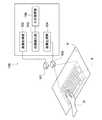
図1は、第1の実施形態に係る情報処理装置100の構成を示す模式図である。同図に示すように、情報処理装置100は、撮影部101、画像取得部102、距離検出部103、画像生成部104、画像表示部105及び入力処理部106を有する。撮影部101は画像取得部102と接続され、画像取得部102は距離検出部103に接続されている。距離検出部103は画像生成部104と接続され、画像生成部104は画像表示部105に接続されている。入力処理部106は距離検出部103に接続されている。情報処理装置100は、画像の生成、表示が可能なあらゆる装置、例えば、パーソナルコンピュータ等の各種コンピュータ、携帯電話、携帯型情報端末等であるものとすることができる。[Configuration of information processing device]
FIG. 1 is a schematic diagram illustrating a configuration of an
図1においては、投影面P(例えば、机など)に画像表示部105によって表示対象物(例えばキーボード)の画像(以下、表示画像)Sが投影されている。ユーザが表示画像Sを参照して投影面Pに対して入力操作(例えばタイピング)を実施しているものとし、ユーザの手を手Hとして示す。 In FIG. 1, an image (hereinafter referred to as a display image) S of a display object (for example, a keyboard) is projected on a projection plane P (for example, a desk) by an
撮影部101は、CCD(Charge Coupled Device)やCMOS(Complementary Metal Oxide Semiconductor)等の撮像素子と必要な光学系を備え、撮影範囲の画像を撮影する。撮影部101は、その合焦距離(撮影部101と焦点の距離)を変更可能なものであり、画像取得部102による制御を受けて合焦距離(フォーカス)を変更するものとすることができる。撮影部101は、撮影した画像(以下、撮影画像)を画像取得部102に出力する。 The
画像取得部102は、撮影部101によって撮影された撮影画像を取得し、距離検出部103に供給する。画像取得部102は、撮影部101を制御し、その合焦距離を変更すると共に画像を撮影させるものとすることができる。詳細は後述するが、画像取得部102は、複数の合焦距離で撮影部101に撮影画像を撮影させるものとすることができる。 The
距離検出部103は、画像取得部102から供給された複数の撮影画像に対して所定の画像処理を実行し、撮影部101の撮影範囲に含まれる物体(ここではユーザの手H)と撮影部101の距離(以下、物体距離とする)を検出する。距離検出部103は物体距離を入力処理部106及び画像生成部104に供給する。 The
画像生成部104は、画像取得部102から供給された複数の撮影画像に対して所定の画像処理を実行し、その処理結果に基づいて画像表示部105によって表示される表示画像Sを生成する。詳細は後述するが、画像生成部104は、物体距離に基づいて画像マスクを生成し、この画像マスクを用いて表示画像Sを生成する。 The
画像表示部105は、画像の投影が可能なもの(プロジェクタ)であり、画像生成部104によって生成された表示画像Sを投影面Pに投影する。画像表示部105は、任意の方式のプロジェクタであるものとすることができる。画像表示部105は撮影部101と近接して配置されているものが好適である。 The
入力処理部106は、距離検出部103から供給された物体距離に基づいてユーザの操作入力を判断し、操作入力に対する入力処理を実行する。詳細は後述するが、入力処理部106は、投影面Pに対してのユーザの手Hの接触を検出し、その接触箇所と表示画像Sの位置関係から、ユーザの操作入力を判断するものとすることができる。入力処理部106によって生成された入力処理は、情報処理装置100のオペレーティングシステムに供給される。 The
情報処理装置100は以上のような構成を有する。画像取得部102、距離検出部103、画像生成部104及び入力処理部106は、ソフトウェアとハードウェアの協働によって実現される機能的構成であるものとすることができ、物理的に情報処理装置100の筐体に収容されているものに限られず、ネットワーク上に実装されているものであってもよい。 The
[情報処理装置の動作]
図2は、情報処理装置100の動作を示すフローチャートである。[Operation of information processing device]
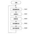
FIG. 2 is a flowchart showing the operation of the
図2に示すように、画像取得部102は、撮影画像を取得する(St101)。図3は、画像取得部102による撮影画像の取得に係るフローチャートであり、図4は撮影画像の取得の様子を示す模式図である。 As shown in FIG. 2, the
図3に示すように、画像取得部102は撮影部101を制御し、その合焦距離を初期値に設定する(St111)。初期値は、撮影部101から投影面Pが十分に含まれると予想される距離であり、撮影部101の情報処理装置100における配置等に応じて設定することが可能である。図4に、初期値の合焦距離を含む面をA面として示す。 As shown in FIG. 3, the
画像取得部102は、撮影部101に当該合焦距離(A面)で画像を撮影させる(St112)。画像取得部102は、A面において撮影された撮影画像に対して合焦領域の抽出(St112)を実行する。合焦領域は、撮影画像において焦点が合っている領域であり、例えば撮影画像における各画素のコントラスト、あるいは位相差から検出することが可能である。 The
続いて画像取得部102は、撮影画像において合焦領域が検出されたか否かを確認する(St113)。画像取得部102は合焦領域を検出した場合(St114;Yes)、合焦距離を移動させる(St115)。具体的には、画像取得部102は、合焦距離を初期値(A面)から撮影部101のより近傍(B面)に変更させる。A面とB面の間隔は任意であり、被写界深度が浅ければ、例えば数mmとすることができる。 Subsequently, the
画像取得部102は、合焦領域が検出されている限りにおいて合焦距離の変更と撮影以下のプロセスを繰り返し実行する。画像取得部102は、合焦領域を検出しなかった場合(St114、No)、撮影画像の取得を終了する。例えば図4においては最後に合焦領域が検出される(手Hが存在する)合焦距離がC面にあるとすると、撮影画像の撮影はA面とC面の間で所定間隔で実行されることになる。なお、A面とC面の間で所定間隔で実行された際に、投影面Pの手前にも合焦領域が検出されるが、投影面Pが机のような平面あるいは手と比較して凸凹が少ない曲面では、投影面Pでの合焦領域はほとんど直線状を成し、あきらかに手のような立体物とは異なる合焦領域データとなりうるため、削除できる。 As long as the in-focus area is detected, the
以上のようにして画像取得部102は、少なくともユーザの手Hが含まれる範囲において所定の間隔で撮影された複数の撮影画像を取得する。また、画像取得部102は、物体(手H)の検出に利用した合焦領域のデータを保持しておく。 As described above, the
続いて図2に戻り、距離検出部103は、撮影部101の撮影範囲に含まれる物体(手H)の撮影部101との距離(物体距離)を検出する(St102)。具体的には、距離検出部103は、各撮影画像における合焦領域の分布から、各撮影画像毎に手Hの位置を特定することによって物体の立体的な配置(手Hの各部と撮影部101の距離)を検出することが可能である。距離検出部103は物体距離を画像生成部104に供給する。 Subsequently, returning to FIG. 2, the
続いて、画像生成部104は、画像マスクを生成する(St103)。画像生成部104は、距離検出部103によって検出された物体距離を用いて投影面Pより撮影部101に近接する面(例えばC面)に投射される手Hの形状を求め、画像マスクとする。図5は画像生成部104によって生成される画像マスクMの例を示す。 Subsequently, the
続いて画像生成部104は、必要に応じて画像マスクMの最適化を実行する(St104)。図6及び図7は、画像生成部104による画像マスクMの最適化を示す模式図である。画像生成部104は、例えば、図6に示すように画像マスクMを所定の割合(例えば5〜10%程度)で拡大させるものとすることができる。あるいは投影面Pでの影が気になるのであれば所定の割合(例えば−5〜−10%程度)で縮小させるなどマスク最適値は連続的に増減できる。また画像生成部104は、図7に示すように、画像マスクMの境界を不鮮明化させることも可能である。このような画像マスクMの最適化により、従来の指の側面などに投影される見苦しい余分な投影が低減され、後述する表示画像Sの視認性を向上させることが可能となる。境界の不鮮明化により境界線の曖昧さが生じさせることにより、指の細かな動きに対して実時間でその都度マスクデータを高速で更新する必要がなくなるため、情報処理の低減ができ、電池使用機器では使用時間の増大が望める。 Subsequently, the
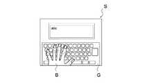
続いて画像生成部104は、画像マスクMを用いて表示画像Sを生成する(St105)。図8は、画像生成部104による表示画像Sの生成を示す模式図である。同図に示すように、画像生成部104は、画像マスクMを表示対象物(ここではキーボード)の画像(以下、表示対象物画像)Gに合成し、表示画像Sを生成する。 Subsequently, the
続いて画像生成部104は、生成した表示画像Sを画像表示部105に供給し、投影させる(St106)。図9は画像表示部105によって投影される表示画像Sを示す図である。同図に示すように、画像マスクMには表示対象物画像Gが表示されないので、表示対象物画像Gがユーザの手H上に投影されず、視認性の悪化を防止することが可能である。この際、画像生成部104は、画像マスクMに相当する領域の描写に必要な電力をカットする電力制御を実行してもよい。 Subsequently, the
なお、表示画像Sの生成及び投影と並行して、入力処理部106は、ユーザの操作入力に対する入力処理を実行する。入力処理部106は、距離検出部103から供給される手Hと撮影部101の距離(物体距離)から、手Hが投影面Pに接触しているか否かを判断することが可能である。入力処理部106は、例えば手Hの投影面Pへの接触箇所と表示画像Sの位置関係から、ユーザの操作入力を判断するものとすることができる。 In parallel with the generation and projection of the display image S, the
以上のように、本実施形態においては、異なる合焦距離で撮影された複数の撮影画像から撮影範囲に含まれる物体(手H)と撮影部101の距離を検出することが可能であり、当該距離を利用して画像マスクを生成することが可能である。これにより、手Hへの表示対象物画像Gの投影が防止され、ユーザの視認性の悪化を防止することができる。 As described above, in the present embodiment, it is possible to detect the distance between the object (hand H) included in the shooting range and the
(第2の実施形態)
本技術の第2の実施形態に係る情報処理装置について説明する。(Second Embodiment)
An information processing apparatus according to the second embodiment of the present technology will be described.
[情報処理装置の構成]
図10は、第2の実施形態に係る情報処理装置200の構成を示す模式図である。同図に示すように、情報処理装置200は、撮影部201、画像取得部202、距離検出部203、画像生成部204、画像表示部205及び入力処理部206を有する。撮影部201は画像取得部202と接続され、画像取得部202は距離検出部203に接続されている。距離検出部203は画像生成部204と接続され、画像生成部204は画像表示部205に接続されている。入力処理部206は距離検出部203に接続されている。情報処理装置200は、画像の生成、表示が可能なあらゆる装置、例えば、パーソナルコンピュータ等の各種コンピュータ、携帯電話、携帯型情報端末等であるものとすることができる。[Configuration of information processing device]
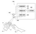
FIG. 10 is a schematic diagram illustrating a configuration of the
図10においては、ユーザが何も表示されていない操作面P(普通の机など)に対して入力操作(例えばタイピングの動作)を実施しているものとし、ユーザの手を手Hとして示す。手Hを含む操作面Pが撮影部201によって撮影され、手Hの画像と、表示対象物(例えばキーボード)の画像が合成された画像が表示画像Sとして画像表示部205に表示されているものとする。 In FIG. 10, it is assumed that an input operation (for example, typing operation) is performed on the operation surface P (normal desk or the like) on which no user is displayed, and the user's hand is indicated as a hand H. An operation surface P including a hand H is photographed by the photographing
撮影部201は、CCD(Charge Coupled Device)やCMOS(Complementary Metal Oxide Semiconductor)等の撮像素子と必要な光学系を備え、撮影範囲の画像を撮影する。撮影部201は、その合焦距離(撮影部201と焦点の距離)を変更可能なものであり、画像取得部202による制御を受けて合焦距離(フォーカス)を変更するものとすることができる。撮影部201は、撮影した画像(以下、撮影画像)を画像取得部202に出力する。撮影部201は、画像表示部205(ディスプレイ等)に搭載されているものが好適である。 The
画像取得部202は、撮影部201によって撮影された撮影画像を取得し、距離検出部203に供給する。画像取得部202は、撮影部201を制御し、その合焦距離を変更すると共に画像を撮影させるものとすることができる。詳細は後述するが、画像取得部202は、複数の合焦距離で撮影部201に撮影画像を撮影させるものとすることができる。 The
距離検出部203は、画像取得部202から供給された複数の撮影画像に対して所定の画像処理を実行し、撮影部201の撮影範囲に含まれる物体(ここではユーザの手H)と撮影部201の距離(以下、物体距離とする)を検出する。距離検出部203は物体距離を入力処理部206及び画像生成部204に供給する。 The
画像生成部204は、画像取得部202から供給された複数の撮影画像に対して所定の画像処理を実行し、その処理結果に基づいて画像表示部205によって表示される表示画像Sを生成する。詳細は後述するが、画像生成部204は、物体距離に基づいて撮影画像から手Hの画像を抽出し、この手Hの画像を用いて表示画像Sを生成する。 The
画像表示部205は、画像の表示が可能なもの(ディスプレイ)であり、画像生成部204によって生成された表示画像Sを表示画面に表示する。画像表示部205は、任意の方式のディスプレイであるものとすることができる。上述のように画像表示部205には撮影部201が搭載されるものとすることができる。 The
入力処理部206は、距離検出部203から供給された物体距離に基づいてユーザの操作入力を判断し、操作入力に対する入力処理を実行する。詳細は後述するが、入力処理部206は、操作面Pに対してのユーザの手Hの接触を検出し、その接触箇所と撮影部201の位置関係から、ユーザの操作入力を判断するものとすることができる。入力処理部206によって生成された入力処理は、情報処理装置200のオペレーティングシステムに供給される。 The
情報処理装置200は以上のような構成を有する。画像取得部202、距離検出部203、画像生成部204及び入力処理部206は、ソフトウェアとハードウェアの協働によって実現される機能的構成であるものとすることができ、物理的に情報処理装置200の筐体に収容されているものに限られず、ネットワーク上に実装されているものであってもよい。 The
[情報処理装置の動作]
図11は、情報処理装置200の動作を示すフローチャートである。[Operation of information processing device]
FIG. 11 is a flowchart showing the operation of the
図11に示すように、画像取得部202は、撮影画像を取得する(St201)。画像取得部202は、第1の実施形態と同様にして撮影画像を取得することが可能である。即ち、画像取得部202は、撮影部201の合焦距離を移動させながら、少なくともユーザの手Hが含まれる範囲において所定の間隔で撮影された複数の撮影画像を取得する。また、画像取得部202は、物体(手H)の検出に利用した合焦領域のデータを保持しておく。 As shown in FIG. 11, the
続いて距離検出部203は、撮影部201の撮影範囲に含まれる物体(手H)の撮影部201との距離(物体距離)を検出する(St202)。具体的には、距離検出部203は、各撮影画像における合焦領域の分布から、各撮影画像毎に手Hの位置を特定することによって物体の立体的な配置(手Hの各部と撮影部201の距離)を検出することが可能である。距離検出部203は物体距離を画像生成部204に供給する。 Subsequently, the
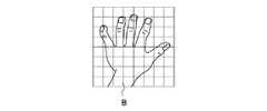
続いて画像生成部204は、物体距離を用いて物体画像(手Hの画像)を抽出する(St203)。具体的には画像生成部204は、画像取得部202によって取得された複数の撮影画像のうちのひとつの画像、例えば最も合焦領域が大きい(焦点が合っている)画像を選択する。画像生成部204は、物体距離を利用してその撮影画像から手Hに相当する画像領域(物体画像)を抽出することができる。図12は画像生成部204によって抽出された物体画像Bを示す模式図である。 Subsequently, the
続いて画像生成部204は、必要に応じて抽出した物体画像Bを変換する(St204)。図12に示すように、物体画像Bは、撮影部201と手Hの位置関係によっては、手Hの撮影部201に接近する側が拡大される場合がある。図13は、変換された物体画像Bを示す模式図である。画像生成部204は図13に示すように物体画像Bの撮影部201に接近する領域を圧縮し、撮影部201から離間する領域を伸張させることによって物体画像Bを変換することができる。これにより、ユーザの視点と撮影部201の視点が異なることによる物体画像Bの変形を防止することができる。 Subsequently, the
続いて画像生成部204は、表示画像を生成する(St205)。図14は画像生成部204によって生成される表示画像Sを示す模式図である。同図に示すように画像生成部204は、物体画像Bと表示対象物(ここではキーボード)の画像(以下、表示対象物画像)Gとを重畳させ、表示画像Sを生成する。画像生成部204はこの際、物体画像Bと表示対象物画像Gの位置合わせを実行する。画像生成部204は例えば、物体画像Bのうち手Hの左小指に相当する領域をキーボードの「Q」キー付近、右小指に相当する領域をキーボードの「Enter」キー付近に合わせるものとすることができる。この位置合わせは頻繁に実行すると、対象物画像Gの描写がぶれるため、最初に表示画像を生成する際に実行すればよい。 Subsequently, the
画像生成部204は、表示画像Sを生成する際、物体画像Bに透過処理を施すことも可能である。図15は、物体画像に透過処理を施して生成される表示画像Sを示す模式図である。同図に示すように物体画像Bに透過処理を施すことによって、表示対象物画像Gが物体画像Bを透過して表示され、ユーザによる視認が可能となる。また、画像生成部204は、透過処理に替わり、物体画像B上に着色を施し、物体画像B(即ち手H)をユーザに明示するものとすることも可能である。 When generating the display image S, the
画像生成部204は、生成した表示画像Sを画像表示部205に出力し、図10に示すようにその表示画面に表示させる(St206)。ユーザは、何も表示されていない操作面Pに対する操作入力を、画像表示部205に表示される表示対象物画像Gを参照して実施することが可能である。 The
なお、表示画像Sの生成及び表示と並行して、入力処理部206は、ユーザの操作入力に対する入力処理を実行する。入力処理部206は、距離検出部203から供給される手Hの各部と撮影部201の距離(物体距離)から、手Hが操作面Pに接触しているか否かを判断することが可能である。入力処理部206は、例えば手Hの操作面Pへの接触箇所と撮影部201の位置関係から、ユーザの操作入力を判断するものとすることができる。 In parallel with the generation and display of the display image S, the
以上のように、本実施形態においては、異なる合焦距離で撮影された複数の撮影画像から撮影範囲に含まれる物体(手H)と撮影部201の距離を検出することが可能であり、当該距離を利用して当該物体の画像を抽出することが可能である。これにより、当該物体と表示対象物画像と合成した表示画像が表示され、ユーザは表示画像を参照して入力処理を実行することが可能となる。 As described above, in the present embodiment, it is possible to detect the distance between the object (hand H) included in the shooting range and the
(第3の実施形態)
本技術の第3の実施形態に係る情報処理装置について説明する。(Third embodiment)
An information processing apparatus according to the third embodiment of the present technology will be described.
[情報処理装置の構成]
図16は、第3の実施形態に係る情報処理装置300の構成を示す模式図である。同図に示すように、情報処理装置300は、撮影部301、画像取得部302、距離検出部303、画像生成部304、画像表示部305及び入力処理部306を有する。撮影部301は画像取得部302と接続され、画像取得部302は距離検出部303に接続されている。距離検出部303は画像生成部304と接続され、画像生成部304は画像表示部305に接続されている。入力処理部306は距離検出部303に接続されている。情報処理装置300は、画像の生成、投影が可能なあらゆる装置、例えば、パーソナルコンピュータ等の各種コンピュータ、携帯電話、携帯型情報端末等であるものとすることができる。[Configuration of information processing device]
FIG. 16 is a schematic diagram illustrating a configuration of an
図16においては、表示対象物(例えばキーボード)の画像(表示画像S)がユーザの手H1の表面である投影面Pに投影されている。ユーザが表示画像Sを参照して投影面Pに対して入力操作(例えばタイピング)を実施しているものとし、入力操作に用いられるユーザの手を手H2として示す。 In FIG. 16, an image (display image S) of a display object (for example, a keyboard) is projected onto a projection plane P that is the surface of the user's hand H1. It is assumed that the user performs an input operation (for example, typing) on the projection plane P with reference to the display image S, and the user's hand used for the input operation is indicated as a hand H2.
撮影部301は、CCD(Charge Coupled Device)やCMOS(Complementary Metal Oxide Semiconductor)等の撮像素子と必要な光学系を備え、撮撮範囲の画像を撮影する。撮影部301は、その合焦距離(撮影部301と焦点の距離)を変更可能なものであり、画像取得部302による制御を受けて合焦距離(フォーカス)を変更するものとすることができる。撮影部301は、撮影した画像(以下、撮影画像)を画像取得部202に出力する。 The
なお撮影部301は、上述の撮像素子だけ限られず、TOF(time-of-flight)方式等の専用の距離画像の計測方式を用いてもよい。TOF方式は、光の到達時間を基に物体の距離を計測するものであり、赤外線等の不可視光をパルス変調して画角内に照射し、撮像素子側でこのパルスの位相遅れを計測することで、物体までの距離を割り出すものである。(参考URL:http://www.nikkei.com/tech/news/article/g=96958A9C93819499E0E6E2E1E48DE0E6E2E0E0E2E3E0E2E2E2E2E2E2;da=96958A88889DE2E4E1E2E5E0E6E2E0E7E2E6E0E2E3E2E2E2E2E2E2E2) Note that the photographing
画像取得部302は、撮影部301によって撮影された撮影画像を取得し、距離検出部303に供給する。画像取得部302は、撮影部301を制御し、その合焦距離を変更すると共に画像を撮影させるものとすることができる。詳細は後述するが、画像取得部302は、複数の合焦距離で撮影部301に撮影画像を撮影させるものとすることができる。 The
距離検出部303は、画像取得部302から供給された複数の撮影画像に対して所定の画像処理を実行し、撮影部301の撮影範囲に含まれる物体(ここでは手H1)と撮影部301の距離(以下、物体距離とする)を検出する。距離検出部303は物体距離を入力処理部306及び画像生成部304に供給する。 The
画像生成部304は、画像取得部302から供給された複数の撮影画像に対して所定の画像処理を実行し、その処理結果に基づいて画像表示部305によって投影される表示画像Sを生成する。詳細は後述するが、画像生成部304は、物体距離に基づいて投影面Pの凹凸を検出し、その凹凸に応じて補正された画像を表示画像Sとして生成する。 The
画像表示部305は、画像の投影が可能なもの(プロジェクタ)であり、画像生成部304によって生成された表示画像Sを投影面Pに投影する。画像表示部305は、任意の方式のプロジェクタであるものとすることができる。画像表示部305は撮影部301と近接して配置されているものが好適である。 The
入力処理部306は、距離検出部303から供給された物体距離に基づいてユーザの操作入力を判断し、操作入力に対する入力処理を実行する。詳細は後述するが、入力処理部306は、投影面Pに対してのユーザの手H2の接触を検出し、その接触箇所と撮影部301の位置関係から、ユーザの操作入力を判断するものとすることができる。入力処理部306によって生成された入力処理は、情報処理装置300のオペレーティングシステムに供給される。 The
情報処理装置300は以上のような構成を有する。画像取得部302、距離検出部303、画像生成部304及び入力処理部306は、ソフトウェアとハードウェアの協働によって実現される機能的構成であるものとすることができ、物理的に情報処理装置300の筐体に収容されているものに限られず、ネットワーク上に実装されているものであってもよい。 The
[情報処理装置の動作]
図17は、情報処理装置300の動作を示すフローチャートである。[Operation of information processing device]
FIG. 17 is a flowchart showing the operation of the
図17に示すように、画像取得部302は、撮影画像を取得する(St301)。画像取得部302は、第1の実施形態と同様にして撮影画像を取得することが可能である。即ち、画像取得部302は、撮影部301の合焦距離を移動させながら、少なくともユーザの手H1が含まれる範囲において所定の間隔で撮影された複数の撮影画像を取得するまた、画像取得部202は、物体(手H1)の検出に利用した合焦領域のデータを保持しておく。 As shown in FIG. 17, the
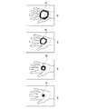
図18は、撮影画像が撮影された合焦距離を含む面を示す模式図である。図18に示す手H1のA面、B面、C面及びD面において撮影画像が撮影されたものとする。図19は各撮影画像における合焦領域を示す模式図である。図19(a)は図18のA面において撮影された撮影画像における合焦領域Rを示し、同様に、図19(b)は図18のB面、図19(c)は図18のC面、図19(d)は図18のD面のそれぞれにおいて撮影された撮影画像における合焦領域Rを示す。図19に示すように、手H1(投影面P)の凹凸に応じて撮影部301との距離が異なるため、各撮影画像において合焦領域の分布が異なる。 FIG. 18 is a schematic diagram illustrating a surface including a focusing distance on which a captured image is captured. It is assumed that the photographed images are photographed on the A surface, the B surface, the C surface, and the D surface of the hand H1 illustrated in FIG. FIG. 19 is a schematic diagram showing a focus area in each captured image. FIG. 19A shows the in-focus area R in the captured image taken on the A plane in FIG. 18. Similarly, FIG. 19B shows the B plane in FIG. 18 and FIG. 19C shows the C in FIG. FIG. 19D shows the in-focus area R in the captured image taken on each of the D planes in FIG. As shown in FIG. 19, since the distance from the
続いて距離検出部303は、撮影部301の撮影範囲に含まれる物体(手H1)の撮影部301との距離(物体距離)を検出する(St302)。具体的には、距離検出部303は、各撮影画像における合焦領域Rの分布から、各撮影画像毎に手H1の位置を特定することによって投影面Pの凹凸(手H1の各部と撮影部301の距離)を検出することが可能である。距離検出部303は物体距離を画像生成部304に供給する。 Subsequently, the
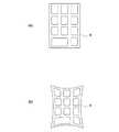
続いて画像生成部304は、物体距離を用いて表示対象物の画像(以下、表示対象物画像)Gの補正を実行する(St303)。図20は、表示対象物画像Gの補正の例を示す模式図である。画像生成部304は、図20(a)に示す表示対象物画像Gを、距離検出部303によって検出された投影面Pの凹凸に合わせて図20(b)に示すように補正する。画像生成部304は、投影面Pのうち、撮影部201に接近している領域(凸領域)に投影される表示対象物画像Gの領域を縮小し、撮影部201から離間している領域(凹領域)に投影される表示対象物画像Gの領域を拡大するように補正することができる。 Subsequently, the
画像生成部304は、上記ように補正した表示対象物画像Gを用いて表示画像Sを生成する(St304)。画像生成部304は、生成した表示画像Sを画像表示部305に出力し、投影面Pに投影させる(St305)。図21は、投影面Pに投影された表示画像Sを示す模式図である。同図に示すように、表示画像Sは投影面Pの凹凸に応じて補正されているため、投影面Pの凹凸による画像の歪みが生じない。 The
なお、表示画像Sの生成及び投影と並行して、入力処理部306は、ユーザの操作入力に対する入力処理を実行する。入力処理部306は、距離検出部303から供給される手H2の各部と撮影部301の距離(物体距離)から、手H2が投影面Pに接触しているか否かを判断することが可能である。入力処理部206は、例えば手H2の投影面Pへの接触箇所と撮影部301の位置関係から、ユーザの操作入力を判断するものとすることができる。 In parallel with the generation and projection of the display image S, the
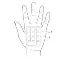
本実施形態においては、検出した物体距離を表示対象物画像Gの生成に利用したが、利用したがこれに限られない。例えば物体距離を利用してユーザの手H1上にマーカを表示するものとすることも可能である。図22はユーザの手H1上に投影されたマーカMを示す模式図である。これにより、ユーザは指の位置を確認し易くなる。また、手Hが操作対象物(キーボード等)に接近するに連れてマーカMの大きさあるいは強度を大きくして表示することも可能である。 In the present embodiment, the detected object distance is used for generating the display target image G. However, the display is not limited to this. For example, a marker can be displayed on the user's hand H1 using the object distance. FIG. 22 is a schematic diagram showing the marker M projected on the user's hand H1. This makes it easier for the user to confirm the finger position. Further, the size or strength of the marker M can be increased and displayed as the hand H approaches the operation target (keyboard or the like).
以上のように、本実施形態においては、異なる合焦距離で撮影された複数の撮影画像から撮影範囲に含まれる物体(手H1)と撮影部301の距離を検出することが可能であり、当該距離を利用して表示対象物画像の補正を実施することが可能である。これにより、当該物体表面(投影面P)の凹凸による画像の歪みが発生せず、ユーザの視認性を良好なものとすることができる。 As described above, in the present embodiment, the distance between the object (hand H1) included in the shooting range and the
本技術は上記各実施形態にのみ限定されるものではなく、本技術の要旨を逸脱しない範囲内において変更することが可能である。 The present technology is not limited only to the above-described embodiments, and can be changed without departing from the gist of the present technology.
上記各実施形態において、表示対象物はキーボードであるものとしたが、これに限られない。例えばマウス等の他の入力装置とすることも可能である。その場合、ポインティング範囲を円や四角などで明示させてもよい。また、上記各実施形態において、撮影部の撮影範囲に含まれる物体はユーザの手であるものとしたが、これに限られない。例えばスタイラス等とすることも可能である。また、手のひらの距離認識時のように撮影部からの距離変化が少ないときは、高速で距離データを更新する必要がない。 In each said embodiment, although the display target object shall be a keyboard, it is not restricted to this. For example, other input devices such as a mouse may be used. In that case, the pointing range may be specified by a circle or a square. Further, in each of the above embodiments, the object included in the shooting range of the shooting unit is the user's hand, but is not limited thereto. For example, a stylus or the like can be used. Further, when there is little change in the distance from the photographing unit as in palm distance recognition, it is not necessary to update the distance data at high speed.
なお、本技術は以下のような構成も採ることができる。
(1)
撮影部によって異なる合焦距離で撮影された複数の撮影画像を取得する画像取得部と、
上記複数の撮影画像に基づいて、上記撮影部の撮影範囲に含まれる物体と上記撮影部の距離を検出する距離検出部と、
上記距離に基づいて、画像表示部によって表示される表示画像を生成する画像生成部と
を具備する情報処理装置。In addition, this technique can also take the following structures.
(1)
An image acquisition unit for acquiring a plurality of captured images taken at different in-focus distances by the imaging unit;
A distance detection unit that detects a distance between an object included in the imaging range of the imaging unit and the imaging unit based on the plurality of captured images;
An information processing apparatus comprising: an image generation unit that generates a display image displayed by the image display unit based on the distance.
(2)
上記(1)に記載の情報処理装置であって、
上記画像取得部は、上記複数の撮影画像のそれぞれにおいて、焦点が合っている領域である合焦領域を抽出し、
上記距離検出部は、上記合焦領域の分布に基づいて上記距離を検出する
情報処理装置。(2)
The information processing apparatus according to (1) above,
The image acquisition unit extracts an in-focus area that is an in-focus area in each of the plurality of captured images.
The distance detection unit detects the distance based on the distribution of the focus area.
(3)
上記(1)又は(2)に記載の情報処理装置であって、
上記画像生成部は、上記距離に基づいて、表示対象物の画像である表示対象物画像に変更を加え、上記表示画像を生成する
情報処理装置。(3)
The information processing apparatus according to (1) or (2) above,
The image generation unit changes the display object image, which is an image of the display object, based on the distance, and generates the display image.
(4)
上記(1)から(3)のうちいずれか一つに記載の情報処理装置であって、
上記画像生成部は、上記距離に基づいて画像マスクを生成し、上記画像マスクを上記表示対象物画像と合成して上記表示画像を生成する
情報処理装置。(4)
The information processing apparatus according to any one of (1) to (3) above,
The image generation unit generates an image mask based on the distance, and generates the display image by combining the image mask with the display object image.
(5)
上記(1)から(4)のうちいずれか一つに記載の情報処理装置であって、
上記画像生成部は、上記距離に基づいて上記物体の画像を抽出し、上記物体の画像を上記表示対象物画像と合成して上記表示画像を生成する
情報処理装置。(5)
The information processing apparatus according to any one of (1) to (4) above,
The image generation unit extracts an image of the object based on the distance, and combines the image of the object with the display object image to generate the display image.
(6)
上記(1)から(5)のうちいずれか一つに記載の情報処理装置であって、
上記画像生成部は、上記距離に基づいて上記物体の凹凸を検出し、上記表示対象物画像を上記凹凸に応じて補正し、上記表示画像を生成する
情報処理装置。(6)
The information processing apparatus according to any one of (1) to (5) above,
The image generation unit detects unevenness of the object based on the distance, corrects the display object image according to the unevenness, and generates the display image.
(7)
上記(1)から(6)のうちいずれか一つに記載の情報処理装置であって、
上記表示対象物画像は、入力装置の画像である
情報処理装置。(7)
The information processing apparatus according to any one of (1) to (6) above,
The display object image is an image of an input device.
(8)
上記(1)から(7)のうちいずれか一つに記載の情報処理装置であって、
上記画像取得部は、上記距離に基づいて、上記撮影部が撮影する合焦距離の範囲を制御する
情報処理装置。(8)
The information processing apparatus according to any one of (1) to (7) above,
The image acquisition unit controls an in-focus distance range captured by the imaging unit based on the distance.
(9)
上記(1)から(8)のうちいずれか一つに記載の情報処理装置であって、
上記距離に基づいて、ユーザによる操作入力を処理する入力処理部をさらに具備する
情報処理装置。(9)
The information processing apparatus according to any one of (1) to (8) above,
An information processing apparatus further comprising an input processing unit that processes an operation input by a user based on the distance.
(10)
異なる合焦距離で複数の撮影画像を撮影する撮影部と、
上記複数の撮影画像を取得する画像取得部と、
上記撮影画像に基づいて、上記撮影部の撮影範囲に含まれる物体と上記撮影部の距離を検出する距離検出部と、
上記距離に基づいて、表示画像を生成する画像生成部と、
上記表示画像を表示する画像表示部と
を具備する情報処理装置。(10)
A shooting unit that takes a plurality of shot images at different in-focus distances;
An image acquisition unit for acquiring the plurality of captured images;
A distance detection unit that detects a distance between an object included in the imaging range of the imaging unit and the imaging unit based on the captured image;
An image generating unit that generates a display image based on the distance;
An information processing apparatus comprising: an image display unit that displays the display image.
(11)
上記(10)に記載の情報処理装置であって、
上記画像表示部は、上記表示画像を投影面に投影する
情報処理装置。(11)
The information processing apparatus according to (10) above,
The image display unit projects the display image onto a projection surface.
(12)
上記(10)又は(11)に記載の情報処理装置であって、
上記画像表示部は、上記表示画像を表示画面に表示する
情報処理装置。(12)
The information processing apparatus according to (10) or (11) above,
The image display unit displays the display image on a display screen.
(13)
撮影部によって異なる合焦距離で撮影された複数の撮影画像を取得する画像取得部と、
上記複数の撮影画像に基づいて、上記撮影部の撮影範囲に含まれる物体と上記撮影部の距離を検出する距離検出部と、
上記距離に基づいて、画像表示部によって表示される表示画像を生成する画像生成部と
として情報処理装置を機能させるプログラム。(13)
An image acquisition unit for acquiring a plurality of captured images taken at different in-focus distances by the imaging unit;
A distance detection unit that detects a distance between an object included in the imaging range of the imaging unit and the imaging unit based on the plurality of captured images;
A program that causes an information processing apparatus to function as an image generation unit that generates a display image displayed by an image display unit based on the distance.
(14)
画像取得部が、撮影部によって異なる合焦距離で撮影された複数の撮影画像を取得し、
距離検出部が、上記複数の撮影画像に基づいて、上記撮影部の撮影範囲に含まれる物体と上記撮影部の距離を検出し、
画像生成部が、上記距離に基づいて、画像表示部によって表示される表示画像を生成する
情報処理方法。(14)
The image acquisition unit acquires a plurality of captured images captured at different in-focus distances by the imaging unit,
A distance detection unit detects a distance between an object included in the imaging range of the imaging unit and the imaging unit based on the plurality of captured images,
An information processing method in which an image generation unit generates a display image displayed by an image display unit based on the distance.
100、200、300…情報処理装置
101、201、301…撮影部
102、202、302…画像取得部
103、203、303…距離検出部
104、204、304…画像生成部
105、205、305…画像表示部
106、206、306…入力処理部DESCRIPTION OF
Claims (12)
Translated fromJapanese前記合焦領域の分布に基づいて、前記撮影部の撮影範囲に含まれる物体の立体的な配置を検出する距離検出部と、
前記立体的な配置に基づいて、表示対象物の画像である表示対象物画像に変更を加え、画像表示部によって表示される表示画像を生成する画像生成部と
を具備する情報処理装置。An image acquisition unit that acquires a plurality of captured images captured at different in-focus distances by the imaging unit,and extracts a focused area that is a focused area in each of the plurality of captured images ;
A distance detection unit that detects athree-dimensional arrangement of an object included in the imaging range of the imaging unit based onthe distribution of thefocus area ;
An information processing apparatus comprising: an image generation unit configuredto change a display target image that is an image of a display target based on thethree-dimensional arrangement and generate a display image displayed by the image display unit.
前記画像生成部は、前記立体的な配置に基づいて画像マスクを生成し、前記画像マスクを前記表示対象物画像と合成して前記表示画像を生成する
情報処理装置。The information processing apparatus according to claim1 ,
The image generation unit generates an image mask based on thethree-dimensional arrangement, and combines the image mask with the display object image to generate the display image.
前記画像生成部は、前記立体的な配置に基づいて前記物体の画像を抽出し、前記物体の画像を前記表示対象物画像と合成して前記表示画像を生成する
情報処理装置。An information processing apparatus according to claim2 ,
The image generation unit extracts an image of the object based on thethree-dimensional arrangement , and generates the display image by combining the image of the object with the display target image.
前記画像生成部は、前記立体的な配置に基づいて前記物体の凹凸を検出し、前記表示対象物画像を前記凹凸に応じて補正し、前記表示画像を生成する
情報処理装置。An information processing apparatus according to claim2 ,
The image generation unit detects unevenness of the object based on thethree-dimensional arrangement , corrects the display target image according to the unevenness, and generates the display image.
前記表示対象物画像は、入力装置の画像である
情報処理装置。An information processing apparatus according to any one of claims2 to4 ,
The display object image is an image of an input device.
前記画像取得部は、前記立体的な配置に基づいて、前記撮影部が撮影する合焦距離の範囲を制御する
情報処理装置。An information processing apparatus according to any one of claims 1 to5 ,
The image acquisition unit controls an in-focus distance range captured by the imaging unit based on thestereoscopic arrangement .
前記立体的な配置に基づいて、ユーザによる操作入力を処理する入力処理部をさらに具備する
情報処理装置。The information processing apparatus according to any one of claims 1 to6 ,
An information processing apparatus further comprising an input processing unit that processes an operation input by a user based on thethree-dimensional arrangement .
前記複数の撮影画像を取得し、前記複数の撮影画像のそれぞれにおいて、焦点があっている領域である合焦領域を抽出する画像取得部と、
前記合焦領域の分布に基づいて、前記撮影部の撮影範囲に含まれる物体の立体的な配置を検出する距離検出部と、
前記立体的な配置に基づいて、表示対象物の画像である表示対象物画像に変更を加え、画像表示部によって表示される表示画像を生成する画像生成部と
前記表示画像を表示する画像表示部と
を具備する情報処理装置。A shooting unit that takes a plurality of shot images at different in-focus distances;
An image acquisition unit that acquires theplurality of captured images and extracts a focused area that is a focused area in each of the plurality of captured images ;
A distance detection unit that detects athree-dimensional arrangement of an object included in the imaging range of the imaging unit based onthe distribution of thefocus area ;
An image generation unit that generates a display image to be displayed byan image display unit bychanging a display target image that is an image of a display target based on thethree-dimensional arrangement , and an image display unit that displays the display image An information processing apparatus comprising:
前記画像表示部は、前記表示画像を投影面に投影する
情報処理装置。The information processing apparatus according to claim8 ,
The image display unit is an information processing apparatus that projects the display image onto a projection surface.
前記画像表示部は、前記表示画像を表示画面に表示する
情報処理装置。The information processing apparatus according to claim8 ,
The image display unit displays the display image on a display screen.
前記合焦領域の分布に基づいて、前記撮影部の撮影範囲に含まれる物体の立体的な配置を検出する距離検出部と、
前記立体的な配置に基づいて、表示対象物の画像である表示対象物画像に変更を加え、画像表示部によって表示される表示画像を生成する画像生成部と
して情報処理装置を機能させるプログラム。An image acquisition unit that acquires a plurality of captured images captured at different in-focus distances by the imaging unit,and extracts a focused area that is a focused area in each of the plurality of captured images ;
A distance detection unit that detects athree-dimensional arrangement of an object included in the imaging range of the imaging unit based onthe distribution of thefocus area ;
A program for causing an information processing apparatus to function as an image generation unitthat changes a display target image that is an image of a display target based on thethree-dimensional arrangement and generates a display image displayed by the image display unit .
距離検出部が、前記合焦領域の分布に基づいて、前記撮影部の撮影範囲に含まれる物体の立体的な配置を検出し、
画像生成部が、前記立体的な配置に基づいて、表示対象物の画像である表示対象物画像に変更を加え、画像表示部によって表示される表示画像を生成する
情報処理方法。Image acquisition unitacquires a plurality of images captured by different focusing distances by the photographing unit,in each of the plurality of captured images, extracts a focus area is an area in focus,
A distance detection unit detectsa three-dimensional arrangement of an object included in the shooting range of the shooting unit based onthe distribution of thefocus area ,
An information processing method in which an image generation unitchanges a display object image, which is an image of a display object , based on thethree-dimensional arrangement , and generates a display image displayed by the image display unit.
Priority Applications (4)
| Application Number | Priority Date | Filing Date | Title |
|---|---|---|---|
| JP2012086195AJP5966535B2 (en) | 2012-04-05 | 2012-04-05 | Information processing apparatus, program, and information processing method |
| US13/849,765US9001034B2 (en) | 2012-04-05 | 2013-03-25 | Information processing apparatus, program, and information processing method |
| EP13161342.4AEP2648082A3 (en) | 2012-04-05 | 2013-03-27 | Information processing apparatus comprising an image generation unit and an imaging unit, related program, and method |
| CN201310108288.XACN103365488B (en) | 2012-04-05 | 2013-03-29 | Information processing device, program, and information processing method |
Applications Claiming Priority (1)
| Application Number | Priority Date | Filing Date | Title |
|---|---|---|---|
| JP2012086195AJP5966535B2 (en) | 2012-04-05 | 2012-04-05 | Information processing apparatus, program, and information processing method |
Publications (3)
| Publication Number | Publication Date |
|---|---|
| JP2013218395A JP2013218395A (en) | 2013-10-24 |
| JP2013218395A5 JP2013218395A5 (en) | 2015-04-09 |
| JP5966535B2true JP5966535B2 (en) | 2016-08-10 |
Family
ID=48190081
Family Applications (1)
| Application Number | Title | Priority Date | Filing Date |
|---|---|---|---|
| JP2012086195AExpired - Fee RelatedJP5966535B2 (en) | 2012-04-05 | 2012-04-05 | Information processing apparatus, program, and information processing method |
Country Status (4)
| Country | Link |
|---|---|
| US (1) | US9001034B2 (en) |
| EP (1) | EP2648082A3 (en) |
| JP (1) | JP5966535B2 (en) |
| CN (1) | CN103365488B (en) |
Families Citing this family (15)
| Publication number | Priority date | Publication date | Assignee | Title |
|---|---|---|---|---|
| CN104272218B (en)* | 2012-06-30 | 2017-03-08 | 惠普发展公司,有限责任合伙企业 | Virtual hand based on joint data |
| CN103809755B (en)* | 2014-02-19 | 2017-11-07 | 联想(北京)有限公司 | A kind of information processing method and electronic equipment |
| US9766806B2 (en) | 2014-07-15 | 2017-09-19 | Microsoft Technology Licensing, Llc | Holographic keyboard display |
| JP6528774B2 (en)* | 2014-07-30 | 2019-06-12 | ソニー株式会社 | INFORMATION PROCESSING APPARATUS, INFORMATION PROCESSING METHOD, AND PROGRAM |
| CN105320258B (en)* | 2014-08-05 | 2019-01-01 | 深圳Tcl新技术有限公司 | Virtual keyboard system and its entering method |
| EP3180721A4 (en) | 2014-08-15 | 2018-04-04 | The University of British Columbia | Methods and systems for performing medical procedures and for accessing and/or manipulating medically relevant information |
| US9898809B2 (en)* | 2015-11-10 | 2018-02-20 | Nanjing University | Systems, methods and techniques for inputting text into mobile devices using a camera-based keyboard |
| US11188143B2 (en)* | 2016-01-04 | 2021-11-30 | Microsoft Technology Licensing, Llc | Three-dimensional object tracking to augment display area |
| US11513637B2 (en) | 2016-01-25 | 2022-11-29 | Hiroyuki Ikeda | Image projection device |
| KR102471422B1 (en) | 2017-02-17 | 2022-11-30 | 엔제트 테크놀러지스 인크. | Method and system for non-contact control in surgical environment |
| JP7286612B2 (en)* | 2018-02-19 | 2023-06-05 | 株式会社村上開明堂 | Operation detection device and operation detection method |
| CN110971821A (en)* | 2019-11-28 | 2020-04-07 | 武汉兴图新科电子股份有限公司 | Method for controlling camera pan-tilt or preset point through keyboard |
| EP4325345A4 (en) | 2021-09-06 | 2024-08-14 | Samsung Electronics Co., Ltd. | ELECTRONIC DEVICE FOR CAPTURING USER INPUT VIA A VIRTUAL KEYBOARD AND OPERATING METHOD THEREFOR |
| US20230136028A1 (en)* | 2021-11-03 | 2023-05-04 | Jin Alexander Yu | Ergonomic eyes-off-hand multi-touch input |
| CN118113151B (en)* | 2023-10-16 | 2024-11-12 | 潍坊幻视软件科技有限公司 | A system for setting colliders for hand input |
Family Cites Families (29)
| Publication number | Priority date | Publication date | Assignee | Title |
|---|---|---|---|---|
| US6621524B1 (en)* | 1997-01-10 | 2003-09-16 | Casio Computer Co., Ltd. | Image pickup apparatus and method for processing images obtained by means of same |
| US6614422B1 (en)* | 1999-11-04 | 2003-09-02 | Canesta, Inc. | Method and apparatus for entering data using a virtual input device |
| JP2002298142A (en)* | 2001-03-29 | 2002-10-11 | Minolta Co Ltd | Person image detecting method, storage medium recording program for executing the method, person image detecting device, and image pick-up device having this device |
| US20030226968A1 (en)* | 2002-06-10 | 2003-12-11 | Steve Montellese | Apparatus and method for inputting data |
| JP3880582B2 (en)* | 2004-02-13 | 2007-02-14 | Necビューテクノロジー株式会社 | Projector with multiple cameras |
| DE102004015947A1 (en)* | 2004-03-25 | 2005-10-13 | Arnold & Richter Cine Technik Gmbh & Co Betriebs Kg | Method and device for adjusting the focus on the camera lens of a motion picture camera |
| US20070115261A1 (en)* | 2005-11-23 | 2007-05-24 | Stereo Display, Inc. | Virtual Keyboard input system using three-dimensional motion detection by variable focal length lens |
| JP2008123316A (en) | 2006-11-14 | 2008-05-29 | Konica Minolta Holdings Inc | Data input method and data input device |
| US7683962B2 (en)* | 2007-03-09 | 2010-03-23 | Eastman Kodak Company | Camera using multiple lenses and image sensors in a rangefinder configuration to provide a range map |
| KR101378329B1 (en)* | 2007-09-28 | 2014-03-27 | 삼성전자주식회사 | Digital photographing apparatus, method for controlling the same, and recording medium storing program to implement the method |
| JP5173665B2 (en)* | 2008-08-08 | 2013-04-03 | キヤノン株式会社 | Image capturing apparatus, distance calculation method thereof, and focused image acquisition method |
| US8736751B2 (en)* | 2008-08-26 | 2014-05-27 | Empire Technology Development Llc | Digital presenter for displaying image captured by camera with illumination system |
| US8339503B2 (en)* | 2008-09-10 | 2012-12-25 | Panasonic Corporation | Lens barrel and imaging device |
| JP5038283B2 (en)* | 2008-11-05 | 2012-10-03 | キヤノン株式会社 | Imaging system and lens device |
| JP5294805B2 (en)* | 2008-11-05 | 2013-09-18 | キヤノン株式会社 | Imaging system and lens device |
| TW201026034A (en)* | 2008-12-31 | 2010-07-01 | Altek Corp | Automatic focusing method in high-noise environment and the device thereof |
| KR20100080704A (en)* | 2009-01-02 | 2010-07-12 | 삼성전자주식회사 | Method and apparatus for obtaining image data |
| US8199248B2 (en)* | 2009-01-30 | 2012-06-12 | Sony Corporation | Two-dimensional polynomial model for depth estimation based on two-picture matching |
| WO2011106797A1 (en)* | 2010-02-28 | 2011-09-01 | Osterhout Group, Inc. | Projection triggering through an external marker in an augmented reality eyepiece |
| US20110234481A1 (en)* | 2010-03-26 | 2011-09-29 | Sagi Katz | Enhancing presentations using depth sensing cameras |
| US8045046B1 (en)* | 2010-04-13 | 2011-10-25 | Sony Corporation | Four-dimensional polynomial model for depth estimation based on two-picture matching |
| US20120200673A1 (en)* | 2010-06-15 | 2012-08-09 | Junichi Tagawa | Imaging apparatus and imaging method |
| CN101930338A (en)* | 2010-07-19 | 2010-12-29 | 苏州佳世达电通有限公司 | Touch system and control method thereof |
| US20130135199A1 (en)* | 2010-08-10 | 2013-05-30 | Pointgrab Ltd | System and method for user interaction with projected content |
| WO2012023004A1 (en)* | 2010-08-18 | 2012-02-23 | Sony Ericsson Mobile Communications Ab | Adaptable projection on occluding object in a projected user interface |
| WO2012037290A2 (en)* | 2010-09-14 | 2012-03-22 | Osterhout Group, Inc. | Eyepiece with uniformly illuminated reflective display |
| EP2642245B1 (en)* | 2010-11-17 | 2020-11-11 | Panasonic Corporation | Image pickup device and distance measuring method |
| US8433187B2 (en)* | 2011-01-18 | 2013-04-30 | DigitalOptics Corporation MEMS | Distance estimation systems and method based on a two-state auto-focus lens |
| WO2012117733A1 (en)* | 2011-03-02 | 2012-09-07 | パナソニック株式会社 | Imaging device, semiconductor integrated circuit, and imaging method |
- 2012
- 2012-04-05JPJP2012086195Apatent/JP5966535B2/ennot_activeExpired - Fee Related
- 2013
- 2013-03-25USUS13/849,765patent/US9001034B2/enactiveActive
- 2013-03-27EPEP13161342.4Apatent/EP2648082A3/ennot_activeWithdrawn
- 2013-03-29CNCN201310108288.XApatent/CN103365488B/ennot_activeExpired - Fee Related
Also Published As
| Publication number | Publication date |
|---|---|
| US20130265219A1 (en) | 2013-10-10 |
| US9001034B2 (en) | 2015-04-07 |
| EP2648082A2 (en) | 2013-10-09 |
| EP2648082A3 (en) | 2016-01-20 |
| CN103365488B (en) | 2018-01-26 |
| CN103365488A (en) | 2013-10-23 |
| JP2013218395A (en) | 2013-10-24 |
Similar Documents
| Publication | Publication Date | Title |
|---|---|---|
| JP5966535B2 (en) | Information processing apparatus, program, and information processing method | |
| JP5822400B2 (en) | Pointing device with camera and mark output | |
| CN104205804B (en) | Image processing device, photographing device and image processing method | |
| JP5450739B2 (en) | Image processing apparatus and image display apparatus | |
| US7944498B2 (en) | Multi-focal camera apparatus and methods and mediums for generating focus-free image and autofocus image using the multi-focal camera apparatus | |
| US10571246B2 (en) | Imaging processing apparatus, distance measuring apparatus and processing system | |
| JP5560721B2 (en) | Image processing apparatus, image display system, and image processing method | |
| CN109218606B (en) | Image pickup control apparatus, control method thereof, and computer readable medium | |
| CN108377342A (en) | Double-camera shooting method and device, storage medium and terminal | |
| JP6251851B2 (en) | Focus control device, focus control method, focus control program, lens device, imaging device | |
| EP3062286A1 (en) | Optical distortion compensation | |
| WO2018045596A1 (en) | Processing method and mobile device | |
| JP6687103B2 (en) | Image processing system, image processing method and program | |
| WO2011096571A1 (en) | Input device | |
| JP2020009099A (en) | Image processing device, image processing method, and program | |
| Lee et al. | Fast-rolling shutter compensation based on piecewise quadratic approximation of a camera trajectory | |
| KR102860387B1 (en) | Method for Stabilization at high magnification and Electronic Device thereof | |
| JP5939469B2 (en) | Browsing device and browsing system | |
| JP6291795B2 (en) | Imaging system and imaging method | |
| JP6236580B2 (en) | Focus control device, focus control method, focus control program, lens device, imaging device | |
| JP6514889B2 (en) | INFORMATION PROCESSING APPARATUS, INFORMATION PROCESSING PROGRAM, INFORMATION PROCESSING SYSTEM, AND INFORMATION PROCESSING METHOD | |
| JP6242009B2 (en) | Video transfer system, terminal, program, and method for displaying a shooting area frame superimposed on a wide area image | |
| US9832377B2 (en) | Data acquiring method and electronic device thereof | |
| JP6919374B2 (en) | Image processing equipment, image processing methods and programs | |
| JP5397245B2 (en) | Information processing apparatus and information processing method |
Legal Events
| Date | Code | Title | Description |
|---|---|---|---|
| A521 | Request for written amendment filed | Free format text:JAPANESE INTERMEDIATE CODE: A523 Effective date:20150218 | |
| A621 | Written request for application examination | Free format text:JAPANESE INTERMEDIATE CODE: A621 Effective date:20150218 | |
| A977 | Report on retrieval | Free format text:JAPANESE INTERMEDIATE CODE: A971007 Effective date:20160127 | |
| A131 | Notification of reasons for refusal | Free format text:JAPANESE INTERMEDIATE CODE: A131 Effective date:20160202 | |
| A521 | Request for written amendment filed | Free format text:JAPANESE INTERMEDIATE CODE: A523 Effective date:20160328 | |
| TRDD | Decision of grant or rejection written | ||
| A01 | Written decision to grant a patent or to grant a registration (utility model) | Free format text:JAPANESE INTERMEDIATE CODE: A01 Effective date:20160607 | |
| A61 | First payment of annual fees (during grant procedure) | Free format text:JAPANESE INTERMEDIATE CODE: A61 Effective date:20160620 | |
| R151 | Written notification of patent or utility model registration | Ref document number:5966535 Country of ref document:JP Free format text:JAPANESE INTERMEDIATE CODE: R151 | |
| R250 | Receipt of annual fees | Free format text:JAPANESE INTERMEDIATE CODE: R250 | |
| LAPS | Cancellation because of no payment of annual fees |