JP5962629B2 - Coke oven construction method - Google Patents
Coke oven construction methodDownload PDFInfo
- Publication number
- JP5962629B2 JP5962629B2JP2013220127AJP2013220127AJP5962629B2JP 5962629 B2JP5962629 B2JP 5962629B2JP 2013220127 AJP2013220127 AJP 2013220127AJP 2013220127 AJP2013220127 AJP 2013220127AJP 5962629 B2JP5962629 B2JP 5962629B2
- Authority
- JP
- Japan
- Prior art keywords
- brick
- wall
- lowermost
- module
- wall module
- Prior art date
- Legal status (The legal status is an assumption and is not a legal conclusion. Google has not performed a legal analysis and makes no representation as to the accuracy of the status listed.)
- Active
Links
Images


Landscapes
- Furnace Housings, Linings, Walls, And Ceilings (AREA)
Description
Translated fromJapanese本発明は、コークス炉の炉体構築方法に関するものである。 The present invention relates to a furnace body construction method for a coke oven.
コークス炉の炉体は、複数の煉瓦を積み上げた煉瓦積み構造体であり、主に、蓄熱室、コーベル、燃焼室、炭化室、及び炉頂からなる。燃焼室と炭化室は炉団方向と呼ばれる方向に沿って交互にそれぞれ複数配列されている。また、燃焼室と炭化室は、燃焼室の周囲を囲む煉瓦壁によって区画されている。燃焼室は、煉瓦壁で周囲を囲まれた領域内においてフリュー(煙道)と呼称される複数の小室に区画されている。 The furnace body of the coke oven is a brick structure in which a plurality of bricks are stacked, and mainly includes a heat storage chamber, a corbel, a combustion chamber, a carbonization chamber, and a furnace top. A plurality of combustion chambers and carbonization chambers are alternately arranged along a direction called a furnace group direction. Further, the combustion chamber and the carbonization chamber are partitioned by a brick wall surrounding the combustion chamber. The combustion chamber is partitioned into a plurality of small chambers called flue (flues) in an area surrounded by a brick wall.
コークス炉では、燃焼室で燃焼ガスを燃焼して発生した熱を煉瓦壁を介して燃焼室から炭化室へ伝熱することで炭化室内の石炭を乾留して炭化し、コークスを生成している。原料となる石炭が投入された炭化室の内部は、石炭の炭化に必要な1000℃以上の温度に熱せられる。炭化が終了すると、炭化室の長手方向において互いに対向する2つの側面の蓋、所謂炉蓋を開放し、一方の側面側(マシンサイド側)から他方の側面側(コークスサイド側)に向けて、生成されたコークスを押出機で押し出す。押し出されたコークスは、炉蓋の外に配置された消火車に収容される。その後、炉蓋を閉じ、更に炭化室の上部に設けられた装入口から原料となる石炭を装入する。コークス炉では、この一連のサイクルを1つの炭化室あたり1日1回程度繰り返している。この一連のサイクルにおいて、炭化室の内部は、コークスを押し出すときや、石炭を装入するときに一時的に冷却される。また、コークスの押し出しに伴う煉瓦壁の摩耗や装入される石炭の衝突等の衝撃も受けている。 In the coke oven, the heat generated by burning the combustion gas in the combustion chamber is transferred from the combustion chamber to the carbonization chamber via the brick wall, so that the coal in the carbonization chamber is carbonized by distillation to produce coke. . The inside of the carbonization chamber into which the coal as the raw material is charged is heated to a temperature of 1000 ° C. or higher necessary for carbonization of the coal. When carbonization is completed, the two side lids facing each other in the longitudinal direction of the carbonization chamber, so-called furnace lids, are opened, from one side (machine side) to the other side (coke side), The produced coke is extruded with an extruder. The extruded coke is accommodated in a fire extinguisher arranged outside the furnace lid. Thereafter, the furnace lid is closed, and coal as a raw material is charged from a charging port provided at the upper part of the carbonization chamber. In the coke oven, this series of cycles is repeated about once a day for one carbonization chamber. In this series of cycles, the inside of the carbonization chamber is temporarily cooled when coke is pushed out or when coal is charged. In addition, there are impacts such as the wear of brick walls and the impact of the coal to be charged due to the extrusion of coke.
こうした操業を繰り返すことから、特に燃焼室の周囲を囲む煉瓦壁は熱的、機械的な衝撃を受け、煉瓦壁を構成する煉瓦の目地や煉瓦内部に亀裂が発生することがある。このような亀裂が進行すると、燃焼室と炭化室とが連通してしまう。このような亀裂による連通が生じると、石炭を装入するときの炭化室内の粉塵が燃焼室に流出したり、石炭を乾留するときに発生するコークス炉ガスの一部が燃焼室側へ流出したりするといった現象を生じ、これら粉塵や石炭ガスが燃焼室内でススとなるなどの影響があり、好ましくない。 Since these operations are repeated, especially the brick wall surrounding the combustion chamber is subjected to thermal and mechanical shocks, and cracks may occur in the joints of the bricks constituting the brick wall and in the bricks. When such a crack progresses, the combustion chamber and the carbonization chamber communicate with each other. If such cracks occur, dust in the carbonization chamber when charging coal flows into the combustion chamber, or a portion of the coke oven gas generated when carbonizing the coal flows out to the combustion chamber. This is not preferable because there is an effect that dust and coal gas become soot in the combustion chamber.
そこで、コークス炉においては、定期的に、煉瓦壁の煉瓦に対して亀裂や角欠けなどの有無を点検し、必要に応じて溶射による補修や、煉瓦壁の積み替えによる部分的な補修が行われている。特許文献1には、大型型成形モジュールを使用してコークス炉を修理する技術が開示されている。この技術は、修理する部分の煉瓦の複数個分の大きさで新たに型成形した大型型成形モジュールを使用することにより、コークス炉において加熱壁を整備する時間を短縮することができるというものである。 Therefore, in the coke oven, the bricks on the brick wall are regularly inspected for cracks and chipped corners, and repaired by thermal spraying or partial repair by replacing the brick wall as necessary. ing. Patent Document 1 discloses a technique for repairing a coke oven using a large mold module. This technology can shorten the time required for maintenance of the heating wall in the coke oven by using a large mold module that has been newly molded in the size of a plurality of bricks to be repaired. is there.
ところで、コークス炉の炉体老朽に伴う全面的な更新では、既設煉瓦を解体した後に築炉工による手積み工法が取られているのが一般的である。この築炉工による手積み工法では、炉体の炉体構築現場において、1段毎に煉瓦積みしており、築炉工の配置上ある程度の密集しか許されないため、構築に掛かる時間をかなり必要とし、炉体構築期間が長くなる。特に、燃焼室の煉瓦壁における積み替え作業は、狭所のため、構築に掛かる時間がさらに長くなる。 By the way, in the full renewal accompanying the furnace body aging of the coke oven, it is general that a hand-built construction method is adopted after the existing brick is demolished. In this method of building by hand construction, bricks are piled up one step at the furnace construction site of the furnace body, and only a certain amount of density is allowed due to the construction of the furnace construction, so a considerable amount of time is required for construction. And the furnace construction period becomes longer. In particular, since the transshipment work on the brick wall of the combustion chamber is narrow, the time required for construction becomes even longer.
そこで、本発明者は、燃焼室の周囲を囲む煉瓦壁が平面方向において閉じた環状形状になっていることに着目し、本発明をなした。
なお、前述の特許文献1の技術においても、炉体の炉体構築現場で大型型成形モジュールを1段毎に煉瓦積みしている。
本発明の目的は、コークス炉の炉体構築期間の短縮を図ることが可能な技術を提供することにある。Therefore, the present inventor made the present invention by paying attention to the fact that the brick wall surrounding the combustion chamber has an annular shape closed in the plane direction.
In the technique of Patent Document 1 described above, large-sized molded modules are bricked one by one at the furnace body construction site of the furnace body.
The objective of this invention is providing the technique which can aim at shortening of the furnace body construction period of a coke oven.
(1)本発明に係るコークス炉の炉体構築方法は、(a)炉体構築現場から離れた別地において、互いに直交する第1及び第2の方向を含む平面方向に複数の煉瓦を並べてなる煉瓦層が前記平面方向と直交する第3の方向に複数段積層された複数の煉瓦壁モジュールを予め形成する工程と、(b)前記炉体構築現場において、前記複数の煉瓦壁モジュールの各々の前記第3の方向が一致するように、前記複数の煉瓦壁モジュールを複数段積層して煉瓦壁を形成する工程と、を備える。 (1) A method for constructing a coke oven according to the present invention includes: (a) a plurality of bricks arranged in a plane direction including a first direction and a second direction orthogonal to each other at a separate site away from a furnace construction site. Forming a plurality of brick wall modules in which a plurality of brick layers are laminated in a third direction orthogonal to the planar direction, and (b) each of the plurality of brick wall modules at the furnace body construction site. Forming a brick wall by laminating the plurality of brick wall modules in a plurality of stages so that the third direction of the first and second directions coincides.
上述した手段(1)によれば、炉体の一部もしくは全体の更新時や新築時において、炉体構築現場に1つの煉瓦壁モジュールを据え付けることにより、その煉瓦壁モジュールの煉瓦層の段数に相当する分の煉瓦積みが完了するので、1段毎に煉瓦積みする場合と比較して、煉瓦壁の構築に掛かる現地施工の時間を短くすることができる。煉瓦壁モジュールの形成においては、築炉工が密集することの制約が緩和され、また複数の煉瓦壁モジュールを同時に形成することも可能である。この結果、コークス炉の炉体構築期間の短縮を図ることができる。 According to the above-mentioned means (1), when one or all of the furnace body is renewed or newly constructed, one brick wall module is installed at the furnace body construction site, so that the number of brick layers of the brick wall module is increased. Since the corresponding amount of brickwork is completed, it is possible to shorten the time for on-site construction required for building the brick wall as compared with the case of brickworking one step at a time. In the formation of the brick wall module, the restriction of the dense construction of the furnace builders is eased, and a plurality of brick wall modules can be formed at the same time. As a result, the furnace construction period of the coke oven can be shortened.
(2)前記手段(1)に記載のコークス炉の炉体構築方法において、
前記煉瓦壁モジュールは、前記第1の方向に延在し、前記第2の方向において互いに離間する第1及び第2の外壁部分と、前記第2の方向に延在し、前記第1の方向において互いに離間し、かつ前記第1及び第2の外壁部分にそれぞれ連結された第3及び第4の外壁部分と、前記第1乃至第4の外壁部分で周囲を囲まれた領域内において前記第2の方向に延在し、前記第1及び第2の外壁部分にそれぞれ連結され、かつ前記第1の方向に所定の間隔をおいて配列された複数の内壁部分とを有し、前記第1及び第2の外壁部分が前記第3及び第4の外壁部分よりも長い平面形状で形成され、かつ前記第1乃至第4の外壁部分からなる外周囲が閉じた環状形状になっており、前記第1乃至第4の外壁部分で周囲を囲まれた領域が、前記複数の内壁部分で区画された複数のフリュー領域を有する燃焼室であることが好ましい。(2) In the method for constructing a coke oven according to the means (1),
The brick wall module extends in the first direction and is spaced apart from each other in the second direction, and extends in the second direction and extends in the first direction. And the third and fourth outer wall portions connected to the first and second outer wall portions, respectively, and in the region surrounded by the first to fourth outer wall portions. A plurality of inner wall portions extending in two directions, connected to the first and second outer wall portions and arranged at predetermined intervals in the first direction, and And the second outer wall portion is formed in a planar shape longer than the third and fourth outer wall portions, and has an annular shape in which the outer periphery composed of the first to fourth outer wall portions is closed, A region surrounded by the first to fourth outer wall portions is the plurality of inner walls. It is preferably a combustion chamber having a plurality of flue regions partitioned in minutes.
前述した手段(2)によれば、煉瓦壁モジュールは、第1乃至第4の外壁部分で周囲を囲まれた燃焼室と、複数の内壁部分で区画された複数のフリュー領域とを有しているので、この複数の煉瓦壁モジュール10を積層することにより、煉瓦壁を構築できると共に、この煉瓦壁で周囲を囲まれた燃焼室を構築することができる。
また、煉瓦壁モジュールは、第1乃至第4の外壁部分からなる外周囲が閉じた環状形状になっており、平面方向において他の煉瓦もしくは他の煉瓦壁モジュールを繋いで燃焼室を構成する必要がないので、炉体構築現場で容易に燃焼室を構築することができる。According to the means (2) described above, the brick wall module has a combustion chamber surrounded by the first to fourth outer wall portions and a plurality of flue regions partitioned by the plurality of inner wall portions. Therefore, by laminating the plurality of
In addition, the brick wall module has an annular shape with the outer periphery made up of the first to fourth outer wall portions closed, and it is necessary to configure a combustion chamber by connecting other bricks or other brick wall modules in the planar direction. Therefore, the combustion chamber can be easily constructed at the furnace construction site.
(3)前記手段(1)又は(2)に記載のコークス炉の炉体構築方法において、
前記(b)工程は、前記複数の煉瓦壁モジュールの各々において、前記煉瓦壁モジュールを据え付ける相手側の煉瓦と、前記煉瓦壁モジュールの最下段の煉瓦との間にモルタルを介在して前記相手側の煉瓦に前記煉瓦壁モジュールを据え付ける据付工程を含み、
前記据付工程において、前記相手側の煉瓦と前記煉瓦壁モジュールの最下段の煉瓦との間に、前記相手側の煉瓦と前記煉瓦壁モジュールの最下段の煉瓦との離間距離を確保するスペーサが設けられていることが好ましい。(3) In the method for constructing a coke oven body according to the means (1) or (2),
In the step (b), in each of the plurality of brick wall modules, a mortar is interposed between a mating brick on which the brick wall module is installed and a lowermost brick of the brick wall module. An installation step of installing the brick wall module on the brick of
In the installation step, a spacer is provided between the mating brick and the lowermost brick of the brick wall module to ensure a separation distance between the mating brick and the lowermost brick of the brick wall module. It is preferable that
前述した手段(3)によれば、煉瓦壁モジュールを据え付ける相手側の煉瓦と煉瓦壁モジュールの最下段の煉瓦との間にモルタルを介在して相手側の煉瓦に煉瓦壁モジュールを据え付ける際、相手側の煉瓦と煉瓦壁モジュールの最下段の煉瓦との離間距離がスペーサによって確保されるので、重量が大きい煉瓦壁モジュールを据え付ける場合においても、モルタルが目地から押し出されることなく、モルタルの厚さを確保することができる。この結果、煉瓦壁モジュールを用いて構築する場合においても、寸法精度の高いコークス炉の炉体を構築することができる。 According to the above means (3), when the brick wall module is installed on the mating brick with the mortar interposed between the mating brick on which the brick wall module is installed and the bottom brick of the brick wall module, The distance between the brick on the side and the bottom brick of the brick wall module is secured by the spacer, so even when installing a heavy brick wall module, the thickness of the mortar can be reduced without being pushed out of the joint. Can be secured. As a result, even when building using a brick wall module, a furnace body of a coke oven with high dimensional accuracy can be built.
(4)前記手段(3)に記載のコークス炉の炉体構築方法において、
前記スペーサは、前記煉瓦壁モジュールの最下段の煉瓦の下面に該下面から突出するようにして予め形成されていることが好ましい。
前述した手段(4)によれば、相手側の煉瓦に煉瓦壁モジュールを据え付ける前に、スペーサを個別に配置する手間を省くことができるので、炉体構築現場での煉瓦壁モジュールの据え付けを容易にすることができる。この結果、寸法精度の高いコークス炉の炉体を構築することができると共に、スペーサを個別に配置する場合と比較してコークス炉の炉体構築期間をさらに短縮することができる。(4) In the method for constructing a coke oven body according to the means (3),
The spacer is preferably formed in advance so as to protrude from the lower surface of the lowermost brick of the brick wall module.
According to the above-mentioned means (4), it is possible to save the trouble of arranging the spacers individually before installing the brick wall module on the other brick, so it is easy to install the brick wall module at the furnace construction site. Can be. As a result, a furnace body of a coke oven with high dimensional accuracy can be constructed, and the furnace body construction period of the coke oven can be further shortened compared to the case where the spacers are individually arranged.
(5)前記手段(2)に記載のコークス炉の炉体構築方法おいて、
前記別地から前記炉体構築現場に前記複数の煉瓦壁モジュールを個々に搬送フレームで搬送する搬送工程をさらに有し、
前記煉瓦壁モジュールは、前記第1の外壁部分の最下段の煉瓦と前記第2の外壁部分の最下段の煉瓦とが前記第2の方向において互いに支持された構造になっており、
前記搬送工程において、前記搬送フレームは、前記第1の外壁部分の最下段の煉瓦と前記第2の外壁部分の最下段の煉瓦とをその内方に向かって挟持することにより前記煉瓦壁モジュールを把持することが好ましい。(5) In the method for constructing a coke oven body according to the means (2),
A transport step of transporting the plurality of brick wall modules individually from the separate ground to the furnace body construction site with a transport frame;
The brick wall module has a structure in which a lowermost brick of the first outer wall portion and a lowermost brick of the second outer wall portion are supported with each other in the second direction,
In the transporting step, the transport frame sandwiches the brick wall module by sandwiching the lowermost brick of the first outer wall portion and the lowermost brick of the second outer wall portion inward. It is preferable to grip.
前述した手段(5)によれば、搬送フレームは、第1の外壁部分の最下段の煉瓦と第2の外壁部分の最下段の煉瓦とをその内方に向かって挟持することにより煉瓦壁モジュールを把持しているので、搬送フレームが煉瓦壁モジュールを把持した状態で相手側の煉瓦にモルタルを介在して煉瓦壁モジュールを据え付けることができる。
また、煉瓦壁モジュールは、第1の外壁部分の最下段の煉瓦と第2の外壁部分の最下段の煉瓦とが第2の方向において互いに支持された構造になっているので、前記第1の外壁部分の最下段の煉瓦と前記第2の外壁部分の最下段の煉瓦とをその内方に向かって挟持しても煉瓦が内方に位置ずれするような不具合を抑制できる。According to the means (5) described above, the transport frame is configured such that the brick wall module is configured by sandwiching the lowermost brick of the first outer wall portion and the lowermost brick of the second outer wall portion inward. Therefore, the brick wall module can be installed with the mortar interposed in the mating brick in a state where the conveyance frame grips the brick wall module.
Further, the brick wall module has a structure in which the lowermost brick of the first outer wall portion and the lowermost brick of the second outer wall portion are supported by each other in the second direction. Even if the lowermost brick of the outer wall portion and the lowermost brick of the second outer wall portion are sandwiched inward, it is possible to suppress a problem that the brick is displaced inward.
(6)前記手段(5)に記載のコークス炉の炉体構築方法おいて、
前記第1の外壁部分の最下段の煉瓦は、前記第1の外壁部分を構成する第1の部分及び前記内壁部分を構成する第2の部分を有し、前記第1の部分の幅が前記第2の部分の幅よりも広いT字形の平面形状で形成され、前記第2の外壁部分の最下段の煉瓦は、前記第2の外壁部分を構成する第1の部分及び前記内壁部分を構成する第2の部分を有し、前記第1の部分の幅が前記第2の部分の幅よりも広いT字形の平面形状で形成されていることが好ましい。(6) In the method for constructing a coke oven body according to the means (5),
The lowermost brick of the first outer wall part has a first part constituting the first outer wall part and a second part constituting the inner wall part, and the width of the first part is Formed in a T-shaped planar shape wider than the width of the second portion, the lowermost brick of the second outer wall portion constitutes the first portion and the inner wall portion constituting the second outer wall portion Preferably, the first portion is formed in a T-shaped planar shape having a width wider than that of the second portion.
前述の手段(6)によれば、第1の外壁部分の最下段の煉瓦と第2の外壁部分の最下段の煉瓦とが第2の方向において互いに支持された状態で第1の方向において互いに隣り合う2つの内壁部分の間隔を確保することができる。 According to the means (6) described above, the lowermost brick of the first outer wall portion and the lowermost brick of the second outer wall portion are mutually supported in the first direction while being supported with each other in the second direction. The space | interval of two adjacent inner wall parts can be ensured.
本願において開示される発明のうち代表的なものによって得られる効果を簡単に説明すれば、下記のとおりである。
本発明によれば、コークス炉の炉体構築期間の短縮を図ることができる。The effects obtained by the representative ones of the inventions disclosed in the present application will be briefly described as follows.
According to the present invention, the furnace body construction period of the coke oven can be shortened.
以下、本発明の一実施形態に係るコークス炉の炉体構築について、図1乃至図19を用いて説明する。なお、図面を見易くするため、図3、図5、図16、図18においては、後述する煉瓦壁モジュールの最下段(1段目)に位置する煉瓦をハッチングで示している。また、図10及び図11は煉瓦壁モジュールの底面図であるため、煉瓦壁モジュールの平面図である図7及び図8に対して第1の外壁部分10aと第2の外壁部分10bとが紙面に向かって上下入れ替わっている。 Hereinafter, the construction of a coke oven furnace according to an embodiment of the present invention will be described with reference to FIGS. In addition, in order to make drawing easy to see, in FIG.3, FIG.5, FIG.16, FIG. 18, the brick located in the lowest step (1st step) of the brick wall module mentioned later is shown by hatching. Since FIGS. 10 and 11 are bottom views of the brick wall module, the first
まず、コークス炉の炉体の構成について図1乃至図3を用いて説明する。
本実施形態に係るコークス炉は、図1乃至図3に示す炉体1を備えている。また、本実施形態に係るコークス炉は、図示していないが、炭槽、移動機(装炭車,押出機,ガイド車,消火車)、消火設備等を備えている。
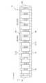
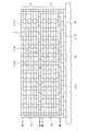
炉体1は、複数の煉瓦2を積み上げた煉瓦積み構造体であり、X方向又はY方向に沿う横目地2bは連続目地であるが、Z方向に沿う縦目地2aは段毎に交互になった千鳥配列をとっている。また、炉体1は、主に、蓄熱室3、コーベル4、燃焼室5、炭化室7、及び炉頂8からなり、燃焼室5と炭化室7とがY方向に沿って交互にそれぞれ複数配列されている。燃焼室5と炭化室7は、燃焼室5の周囲を囲むようにして形成された煉瓦壁6で区画されている。燃焼室5は、煉瓦壁6で周囲を囲まれた領域内において複数のフリュー領域5aに区画されている。First, the structure of the furnace body of a coke oven is demonstrated using FIG. 1 thru | or FIG.
The coke oven according to the present embodiment includes a furnace body 1 shown in FIGS. 1 to 3. In addition, the coke oven according to the present embodiment includes a charcoal tank, a moving machine (a charcoal car, an extruder, a guide car, a fire extinguisher), a fire extinguishing facility, and the like, although not shown.
The furnace body 1 is a brickwork structure in which a plurality of
煉瓦壁6及び炭化室7は、互いに直交するX方向(長手方向)及びY方向(短手方向)を含む平面方向においてX方向に延在し、このX方向を長手方向とする長尺状で形成されている。また、煉瓦壁6及び炭化室7は、X方向及びY方向とそれぞれ直交するZ方向(高さ方向)に高さを有する構成になっている。本実施形態において、煉瓦壁6及び炭化室7は、X方向の長さが約16m程度、Z方向の高さが約6〜8m程度である。また、煉瓦壁6のY方向の幅は約750〜1150mm程度、炭化室7のY方向の幅は約400〜600mm程度である。 The
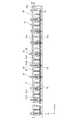
燃焼室5の周囲を囲む煉瓦壁6は、図4乃至図11に示す煉瓦壁モジュール10を用いたモジュール工法で構築されている。本実施形態では、1つの煉瓦壁6に対して5個の煉瓦壁モジュール10が用いられている(図3参照)。煉瓦壁モジュール10は、炉体1の一部もしくは全体の更新時や新築時の構築に用いることができる。
次に、煉瓦壁モジュール10の構成について図4乃至図11を用いて説明する。The
Next, the structure of the
煉瓦壁モジュール10は、X方向及びY方向を含む平面方向において複数の煉瓦2を並べてなる煉瓦層が該平面方向と直交するZ方向に複数段積層された煉瓦積み構造になっている。本実施形態では、煉瓦壁モジュール10は、例えば8段積層構造になっている(図5参照)。
ここで、煉瓦壁モジュール10の説明において、下から数えて第8段目、すなわち最上段の煉瓦層を構成する煉瓦2を個別に煉瓦13と呼ぶこともある。また、下から数えて第1段目、すなわち最下段の煉瓦層を構成する煉瓦2を個別に煉瓦14と呼ぶこともある。The
Here, in the description of the
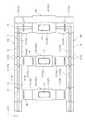
煉瓦壁モジュール10は、X方向に延在し、Y方向において互いに離間する第1及び第2の外壁部分10a,10bと、Y方向に延在し、X方向において互いに離間し、かつ第1及び第2の外壁部分10a,10bのそれぞれに連結された第3及び第4の外壁部分10c,10dとを有している。
また、煉瓦壁モジュール10は、第1乃至第4の外壁部分10a〜10dで周囲を囲まれた領域内においてY方向に延在し、第1及び第2の外壁部分10a,10bのそれぞれに連結され、かつX方向に所定の間隔を置いて配列された複数の内壁部分10eとを有している。The
The
そして、煉瓦壁モジュール10は、第1及び第2の外壁部分10a,10bが第3及び第4の外壁部分10c,10dよりも長い長方形の平面形状で形成されている。
ここで、煉瓦壁モジュール10は、第1乃至第4の外壁部分10a〜10dで周囲を囲まれた領域を有し、この領域は前述した燃焼室5に対応するので、煉瓦壁モジュール10においても燃焼室5と呼ぶ。また、第1乃至第4の外壁部分10a〜10dで周囲を囲まれた領域は複数の内壁部分10eで複数の小室に区画されており、この小室は前述のフリュー領域5aに対応するので、煉瓦壁モジュール10においてもフリュー領域5aと呼ぶ。すなわち、煉瓦壁モジュール10は、第1乃至第4の外壁部分10a〜10dで周囲を囲まれた燃焼室5が、複数の内壁部分10eにより複数のフリュー領域5aに区画されている。The
Here, the
煉瓦壁モジュール10において、X方向及びY方向を含む平面方向において互いに隣り合う2つの煉瓦2の間の縦目地2a、及び、Z方向において互いに隣り合い2つの煉瓦2の間の横目地2bは、モルタル19で充填されている(図6参照)。煉瓦2及びモルタル19は例えば耐熱性の珪石材料で形成されている。
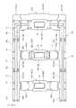
煉瓦壁モジュール10において、最上段(第8段目)の煉瓦層は、図7及び図8に示すように、主に、異形の煉瓦13a〜煉瓦13g、フロント煉瓦と呼称される異形の煉瓦13r〜13t等を含む複数の煉瓦13(煉瓦2)の組み合わせによって構成されている。In the
In the
最上段(第8段目)の煉瓦層において、第1及び第2の外壁部分10a,10bは、煉瓦13a、13b、13c、13d,13e,13r,13sの組み合わせによって形成されている。また、第3及び第4の外壁部分10c,10dは、内方に向かって2列になっており、煉瓦13d,13e,13fからなる列と、煉瓦13r,13s,13tからなる列との組み合わせによって形成されている。また、内壁部分10eは、煉瓦の組み合わせが異なる2種類の内壁部分10e1,10e2があり、一方の内壁部分10e1は煉瓦13b、13fの組み合わせによって形成され、他方の内壁部分10e2は煉瓦13c、13gの組み合わせによって形成されている。 In the uppermost (eighth) brick layer, the first and second
最上段の第1及び第2の外壁部分10a,10bにおいて、煉瓦13a、13b、13c、13d,13eは、X方向においてそれぞれ互いに連結されている。また、最上段の第3及び第4の外壁部分10c,10dにおいて、外側の列を構成する煉瓦13r,13s,13t、内側の列を構成する煉瓦13d,13e,13fは、Y方向において列毎にそれぞれ互いに連結されている。 In the uppermost first and second
煉瓦13b及び13cは、外壁部分及び内壁部分を構成している。第1の外壁部分10a及び内壁部分10e(10e1)を構成する煉瓦13bと、第2の外壁部分10b及び内壁部分10e(10e1)を構成する煉瓦13bとは、煉瓦13fを介在して互いに支持されている。また、第1の外壁部分10a及び内壁部分10e(10e2)を構成する煉瓦13cと、第2の外壁部分10b及び内壁部分10e(10e2)を構成する煉瓦13cとは、煉瓦13gを介在して互いに支持されている。 The
なお、第2段目から第7段目の煉瓦層においても、最上段(第8段目)の煉瓦層と同様の煉瓦13の組み合わせによって構成されている。ただし、同一煉瓦層内(X方向又はY方向)において互いに隣り合う2つの煉瓦2の間の縦目地2aがZ方向(積層方向)において互いに隣り合う2つの煉瓦層に亘って一直線状に繋がるのを避けるため、例えば煉瓦13b及び13fの組み合わせからなる煉瓦群と、煉瓦13c及び13gの組み合わせからなる煉瓦群との配置を段毎(層毎)に入れ替える等の工夫がなされている。 Note that the second to seventh brick layers are also configured by a combination of
煉瓦壁モジュール10において、最下段(第1段目)の煉瓦層は、図10及び図11に示すように、主に、異形の煉瓦14b〜煉瓦14g、フロント煉瓦と呼称される異形の煉瓦14r〜14t等を含む複数の煉瓦14(煉瓦2)の組み合わせによって構成されている。
最下段(第1段目)の煉瓦層において、第1及び第2の外壁部分10a,10bは、煉瓦14b,14c,14d,14e,14r,14sの組み合わせによって形成されている。また、第3及び第4の外壁部分10c,10dは、内方に向かって2列になっており、煉瓦14d,14e,14fからなる列と、煉瓦14r,14s,14tからなる列との組み合わせによって形成されている。また、内壁部分10eは、煉瓦の組み合わせが異なる2種類の内壁部分10e1,10e2があり、一方の内壁部分10e1は煉瓦14b、14fの組み合わせによって形成され、他方の内壁部分10e2は煉瓦14c、14gの組み合わせによって形成されている。In the
In the lowermost (first) brick layer, the first and second
最下段の第1及び第2の外壁部分10a,10bにおいて、煉瓦14b、14c、14d,14eは、X方向においてそれぞれ互いに連結されている。また、最下段の第3及び第4の外壁部分10c,10dにおいて、外側の列を構成する煉瓦14r,14s,14t、内側の列を構成する煉瓦14d,13e,14fは、Y方向において列毎にそれぞれ互いに連結されている。 In the lowermost first and second
煉瓦14b及び14cは、外壁部分及び内壁部分を構成している。煉瓦14b及び14cは、外壁部分(10a,10b)を構成する部分の幅が内壁部分(10e1,10e2)を構成する部分の幅よりも広いT字形の平面形状になっている。すなわち、第1の外壁部分10aの最下段の煉瓦14b,14cは、第1の外壁部分10aを構成する第1の部分14b1,14c1及び内壁部分10eを構成する第2の部分14b2,14c2を有し、この第1の部分14b1,14c1の幅が第2の部分14b2,14c2の幅よりも広いT字形の平面形状で形成されている。また、第2の外壁部分10bの最下段の煉瓦14b,14cも、第2の外壁部分10bを構成する第1の部分14b1,14c1及び内壁部分10eを構成する第2の部分14b2,14c2を有し、この第1の部分14b1,14c1の幅が第2の部分14b2,14c2の幅よりも広いT字形の平面形状で形成されている。 The
煉瓦14d及び14eは、X方向に延在する外壁部分(10a,10b)及びY方向に延在する外壁部分(10c,10d)を構成し、L字形の平面形状になっている。
煉瓦14r及び煉瓦14sは、X方向に延在する外壁部分(10a,10b)とY方向に延在する外壁部分(10c,10d)とが交差する角部に配置されているので、X方向に延在する外壁部分(10a,10b)及びY方向に延在する外壁部分(10c,10d)を構成している。The
Since the
第1の外壁部分10a及び内壁部分10e(10e1)を構成する煉瓦14bと、第2の外壁部分10b及び内壁部分(10e1)を構成する煉瓦14bとは、煉瓦14fを介在して互いに支持されている。また、第1の外壁部分10a及び内壁部分(10e2)を構成する煉瓦14cと、第2の外壁部分10b及び内壁部分(10e2)を構成する煉瓦14cとは、煉瓦14gを介在して互いに支持されている。また、第1の外壁部分10aを構成する煉瓦14rと、第2の外壁部分10bを構成する煉瓦14sとは、煉瓦14tを介在して互いに支持されている。 The
すなわち、本実施形態の煉瓦壁モジュール10は、最下段(第1段目)の煉瓦層において、第1の外壁部分10aを構成する煉瓦(14b,14c,14d,14r)と第2の外壁部分10bを構成する煉瓦(14b,14c,14e,14s)とがY方向において互いに支持された構造になっている。
第2段目〜第8段目(最上段)の煉瓦13f、13g(図8参照)、及び第1段目(最下段)の煉瓦14f、14g(図11参照)は、その厚さ方向、すなわちZ方向に延びる通気孔15を有している。この通気孔15は、各煉瓦層に亘って連通している。煉瓦13や煉瓦14には、通気孔15を通る気体をフリュー領域5aに噴出すための穴が設けられていてもよい。That is, the
The second to eighth (top)
各煉瓦層(各段)の煉瓦2は、図8、図9及び図11に示すように、その厚さ方向(Z方向)において互いに反対側に位置する上面及び下面のうち、上面に嵌合凹部16が設けられ、下面に嵌合凸部17が設けられている。この嵌合凹部16と嵌合凸部17は、Z方向(煉瓦の厚さ方向)において互いに隣り合う上下2つの煉瓦2のずれ止めの役割を持ち、下側の煉瓦2の嵌合凹部16に上側の煉瓦2の嵌合凸部17が嵌め込まれることによって上下2つの煉瓦2の位置決めが成される。 As shown in FIGS. 8, 9, and 11, the
なお、煉瓦壁モジュール10の最下段の煉瓦14(煉瓦2)の嵌合凸部17は、煉瓦壁モジュール10を据え付ける相手側の煉瓦の嵌合凹部、例えば炉体構築現場に最初に据え付ける初段の煉瓦壁モジュール10の場合は炉体構築現場の煉瓦の嵌合凹部に、炉体構築現場に既に据え付けられた下段の煉瓦壁モジュール10に上段の煉瓦壁モジュール10を据え付ける場合は下段の煉瓦壁モジュール10の最上段の煉瓦13の嵌合凹部16に嵌め込まれ、両者の位置決めが成される。 In addition, the fitting
煉瓦壁モジュール10は、最下段(1段目)の煉瓦14の下面にその下面から突出するようにして予め形成された複数のスペーサ18を有している(図9参照)。このスペーサ18は、後で詳細に説明するが、図17及び図19を参照すれば、煉瓦壁モジュール10を据え付ける相手側の煉瓦(25又は13)と、煉瓦壁モジュール10の最下段の煉瓦14(煉瓦2)との間にモルタル19を介在して相手側の煉瓦(25又は13)に煉瓦壁モジュール10を据え付ける際、相手側の煉瓦(25又は13)と煉瓦壁モジュール10の最下段の煉瓦14との間の離間距離tを確保するためのものである。このスペーサ18は、バランスを取るため、1つの煉瓦14に対して複数個設けられている。 The
このように構成された煉瓦壁モジュール10は、炉体1の炉体構築現場から離れた別地で予め形成され、この別地から炉体構築現場に直接搬送、もしくは一旦保管場所に搬送した後に炉体構築現場に搬送される。このときの煉瓦壁モジュール10の搬送は、図12乃至図14に示す搬送フレーム30に把持された状態で行われる。
次に、搬送フレーム30について、図12乃至図14を用いて説明する。The
Next, the
搬送フレーム30は、図12乃至図14に示すように、主にフレーム本体31と、把持機構33とを備えている。フレーム本体31は、煉瓦壁モジュール10の形状に合わせて直方体からなり、煉瓦壁モジュール10をその上方から覆って内部に納めることができる形状になっている。フレーム本体31は、高剛性で軽量化を図るため、上弦材31a、下弦材31b、第1及び第2の束材(鉛直材)31c1,31c2、斜材31d、第1及び第2の横桁(横梁)31e1,31e2等からなるトラス構造になっている。 As shown in FIGS. 12 to 14, the
把持機構33は、煉瓦壁モジュール10の長手方向(X方向)に所定の間隔をおいて複数配置されている。把持機構33は、主に、油圧シリンダ34と、連結アーム35と、把持アーム36と、把持板37とで構成されている。油圧シリンダ34は、シリンダ本体がフレーム本体31の第2の束材31c2の上端に回動自在に支持され、シリンダ軸が連結アーム35の一端側に連結されている。連結アーム35の他端側は把持アーム36の一端側に連結ピンによって回動自在に連結されている。把持アーム36は、中央部がフレーム本体31の第2の横桁31e2の一端側に連結ピンによって回動自在に支持され、他端側には把持板37が連結ピンによって回動自在に連結されている。 A plurality of
把持板37は、煉瓦壁モジュール10の第1の外壁部分10aの最下段の煉瓦2(14)と対向する位置に配置されている。この把持板37に対して、フレーム本体31にも煉瓦壁モジュール10の第2の外壁部分10bの最下段の煉瓦2(14)と対向する位置に把持板38が配置されている。
このように構成された搬送フレーム30は、第1の外壁部分10aの最下段の煉瓦2(14)と第2の外壁部分10bの最下段の煉瓦2(14)とをその内方に向かって2つの把持板37,38が油圧シリンダ34の伸縮動作による荷重で挟持することにより、煉瓦壁モジュール10を把持することができる。The holding
The
次に、煉瓦壁モジュール10を用いたコークス炉の炉体構築について、図15乃至図19を用いて説明する。
まず、炉体1の炉体構築現場(オンサイト)から離れた別地(オフサイト)において、1つの煉瓦壁6に対して5個の煉瓦壁モジュール10を予め形成する(図15の煉瓦壁モジュールの形成工程S11)。煉瓦壁モジュール10は、手積み、すなわち1段毎に煉瓦積みして形成されるが、本実施形態では1つの煉瓦壁6に対して5個の煉瓦壁モジュール10を用いているので、1つの煉瓦壁6に対して最大で5個の煉瓦壁モジュール10を同時進行で形成することができる。Next, the construction of a coke oven furnace using the
First, five
次に、別地にて形成された複数の煉瓦壁モジュール10をこの別地から炉体構築現場に直接搬送、もしくは一旦保管場所に搬送した後に炉体構築現場に搬送する(図15の煉瓦壁モジュールの搬送工程S12)。複数の煉瓦壁モジュール10は、個々に搬送フレーム30に把持された状態で搬送される。具体的には、煉瓦壁モジュール10の搬送は、搬送フレーム30で把持した状態で、運搬車への積載や吊上げをした後、据付位置に設置・着地させる。搬送フレーム30においては、煉瓦壁モジュール10の据え付けを終えると把持を解除し、次の煉瓦壁モジュール10の搬送のために返送され搬送を繰り返す。 Next, a plurality of
この煉瓦壁モジュール10の搬送工程において、搬送フレーム30は、第1の外壁部分10aの最下段の煉瓦14と第2の外壁部分10bの最下段の煉瓦14とをその内方に向かって挟持することにより煉瓦壁モジュール10を把持している。このとき、煉瓦壁モジュール10は、第1の外壁部分10aの最下段の煉瓦14と、第2の外壁部分10bの最下段の煉瓦14とがY方向において、すなわち搬送フレーム30による挟持方向において互いに支持された構造になっているので、搬送フレーム30が第1の外壁部分10aの最下段の煉瓦14と第2の外壁部分10bの最下段の煉瓦14とをその内方に向かって挟持しても、煉瓦14が内方に位置ずれする等の不具合を抑制できる。 In the transport process of the
次に、炉体構築現場において、1つの煉瓦壁6に対して煉瓦壁モジュール10を複数段積層する(図15の煉瓦壁モジュールの据付工程S13)。本実施形態では煉瓦壁モジュール10を5段積層する。具体的には、まず、図16及び図17に示すように、炉体構築現場の煉瓦25と、初段の煉瓦壁モジュール10の最下段の煉瓦2(14)との間にモルタル19を介在した状態で炉体構築現場上に初段の煉瓦壁モジュール10を据え付ける。次に、図18及び図19に示すように、炉体構築現場に既に据え付けた初段の煉瓦壁モジュール10の最上段の煉瓦13と次段の煉瓦壁モジュール10の最下段の煉瓦14との間にモルタル19を介在した状態で初段の煉瓦壁モジュール10上に次段の煉瓦壁モジュール10を据え付ける。この後、同様にして次段の煉瓦壁モジュール10上にさらに次段の煉瓦壁モジュール10を順次据え付ける。 Next, a plurality of
この煉瓦壁モジュール10の据付工程では、初段及び次段の煉瓦壁モジュール10の何れの据え付けにおいても、煉瓦壁モジュール10を据え付ける相手側の煉瓦(初段の煉瓦壁モジュール10を据え付ける場合は炉体構築現場の煉瓦25、次段の煉瓦壁モジュール10を据え付ける場合は前段の煉瓦壁モジュール10の最上段の煉瓦13)と、据え付ける煉瓦壁モジュール10の最下段の煉瓦14との間にモルタル19を介在して行われるが、相手側の煉瓦25又は13と、煉瓦壁モジュール10の最下段の煉瓦14との間には、相手側の煉瓦25又は13と煉瓦壁モジュール10の最下段の煉瓦14との離間距離tを確保するスペーサ18が設けられている。 In the installation process of the
この煉瓦壁モジュール10の据付工程において、炉体構築現場に1つの煉瓦壁モジュール10を据え付けることにより、その煉瓦壁モジュール10の煉瓦層の段数に相当する分の煉瓦積みが完了するので、1段毎に煉瓦積みする場合と比較して、煉瓦壁6の構築に掛かる時間を短くすることができる。
この後、最上段の煉瓦壁モジュール10上に残りの部分を例えば手積みで構築することにより、燃焼室5を囲む煉瓦壁6がほぼ完成する。In this step of installing the
Then, the
ここで、煉瓦壁モジュール10を据え付けるときのモルタル19はペースト状であり、煉瓦壁モジュール10を据え付けた後、乾燥させて硬化させている。ペースト状のモルタル19は、圧縮力により変形し易いので、重量が大きい煉瓦壁モジュール10を据え付ける場合は、設計上必要なモルタル19の厚さを確保することが困難となる。
これに対し、本実施形態では、煉瓦壁モジュール10の据付工程において、初段及び次段の煉瓦壁モジュール10の何れの据え付けにおいても、煉瓦壁モジュール10を据え付ける相手側の煉瓦(初段の煉瓦壁モジュール10を据え付ける場合は炉体構築現場の煉瓦25、次段の煉瓦壁モジュール10を据え付ける場合は前段の煉瓦壁モジュール10の最上段の煉瓦13)と、据え付ける煉瓦壁モジュール10の最下段の煉瓦14との間には相手側の煉瓦25又は13と煉瓦壁モジュール10の最下段の煉瓦14との離間距離tを確保するスペーサ18が設けられているので、重量が大きい煉瓦壁モジュール10を据え付ける場合においても、モルタル19の厚さを適正に保持して寸法精度を確保できる。Here, the
On the other hand, in the present embodiment, in the installation process of the
ここで、煉瓦壁モジュール10は、据付工程において、相手側の煉瓦25又は13にモルタル19を介在して据え付けられるので、搬送フレーム30による搬送では、煉瓦壁モジュール10の底面を把持することが困難である。
これに対し、本実施形態では、搬送フレーム30は第1の外壁部分10aの最下段の煉瓦14と第2の外壁部分10bの最下段の煉瓦14とをその内方に向かって挟持することにより煉瓦壁モジュール10を把持しているので、搬送フレーム30が煉瓦壁モジュール10を把持した状態で相手側の煉瓦にモルタルを介在して煉瓦壁モジュール10を据え付けることができる。Here, the
On the other hand, in the present embodiment, the
また、搬送フレーム30による煉瓦壁モジュール10の把持の際、例えば2段目から8段目の煉瓦2を挟持した場合は、挟持部以下の煉瓦を接着するだけの強度がモルタルには期待できないため、挟持した煉瓦2よりも下段の煉瓦2が落下するおそれがある。これに対し、本実施形態では、最下段の煉瓦14を挟持しているので、煉瓦2の落下を防止することができる。 Further, when the
煉瓦壁モジュール10の搬送は、搬送フレーム30で把持した状態で、運搬車への積載や吊上げをした後、据付位置に着地させて設置する。搬送フレーム30においては、煉瓦壁モジュールの据え付けを終えると把持を解除し、次の煉瓦壁モジュールの搬送のために返送され搬送を繰り返す。
以上のように、本実施形態のコークス炉の炉体構築方法によれば、以下の効果が得られる。The
As described above, according to the furnace body construction method for a coke oven of the present embodiment, the following effects can be obtained.
(1)本実施形態のコークス炉の炉体構築方法は、(a)炉体構築現場から離れた別地において、煉瓦積み構造からなる複数の煉瓦壁モジュール10を予め形成する工程と、(b)炉体構築現場において、複数の煉瓦壁モジュール10の各々の高さ方向(Z方向)が一致するように、複数の煉瓦壁モジュール10を複数段積層して煉瓦壁6を形成する工程とを備えている。 (1) A method for constructing a coke oven for a coke oven according to the present embodiment includes: (a) a step of previously forming a plurality of
したがって、本実施形態のコークス炉の炉体構築方法によれば、炉体の一部もしくは全体の更新時や新築時において、炉体構築現場に1つの煉瓦壁モジュール10を据え付けることにより、その煉瓦壁モジュール10の煉瓦層の段数に相当する分の煉瓦積みが完了するので、1段毎に煉瓦積みする場合と比較して、煉瓦壁6の構築に掛かる時間を短くすることができる。この結果、コークス炉の炉体構築期間の短縮を図ることができる。 Therefore, according to the method for constructing a furnace body of a coke oven of the present embodiment, when one or all of the furnace body is renewed or newly constructed, one
(2)本実施形態のコークス炉の炉体構築方法において、煉瓦壁モジュール10は、第1乃至第4の外壁部分10a〜10dと、この第1乃至第4の外壁部分10a〜10dで周囲を囲まれた領域内においてY方向に所定の間隔をおいて配列された複数の内壁部分10eとを有している。そして、煉瓦壁モジュール10は、第1及び第2の外壁部分10a,10bが第3及び第4の外壁部分10c,10dよりも長い平面形状で形成され、かつ第1乃至第4の外壁部分10a〜10dからなる外周囲が閉じた環状形状になっており、さらに、第1乃至第4の外壁部分10a〜10dで周囲を囲まれた領域が複数の内壁部分10eで区画された複数のフリュー領域5aを有する燃焼室5である構成になっている。 (2) In the furnace body construction method for a coke oven of the present embodiment, the
したがって、本実施形態のコークス炉の炉体構築方法によれば、煉瓦壁モジュール10は、第1乃至第4の外壁部分10a〜10dで周囲を囲まれた燃焼室5と、複数の内壁部分10eで区画されたフリュー領域5aとを有しているので、この複数の煉瓦壁モジュール10を積層することにより、煉瓦壁6を構築できると共に、この煉瓦壁6で周囲を囲まれた燃焼室5を構築することができる。 Therefore, according to the furnace body construction method of the coke oven of the present embodiment, the
また、煉瓦壁モジュール10は、第1乃至第4の外壁部分10a〜10dからなる外周囲が閉じた環状形状になっており、平面方向において他の煉瓦もしくは他の煉瓦壁モジュールを繋いで燃焼室5を構成する必要がないので、炉体構築現場で容易に燃焼室5を構築することができる。
(3)本実施形態のコークス炉の炉体構築方法において、煉瓦壁モジュール10の据付工程では、初段及び次段の煉瓦壁モジュール10の何れの据え付けにおいても、相手側の煉瓦(初段の煉瓦壁モジュール10を据え付ける場合は炉体構築現場の煉瓦25、次段の煉瓦壁モジュール10を据え付ける場合は前段の煉瓦壁モジュール10の最上段の煉瓦13)と、据え付ける煉瓦壁モジュール10の最下段の煉瓦14との間に、相手側の煉瓦25又は13と煉瓦壁モジュール10の最下段の煉瓦14との離間距離tを確保するスペーサ18が設けられている。Further, the
(3) In the coke oven furnace construction method of the present embodiment, in the installation process of the
したがって、本実施形態のコークス炉の炉体構築方法によれば、煉瓦壁モジュール10を据え付ける相手側の煉瓦25又は13と煉瓦壁モジュール10の最下段の煉瓦14との間にモルタル19を介在して相手側の煉瓦25又は13に煉瓦壁モジュール10を据え付ける際、相手側の煉瓦25又は13と煉瓦壁モジュール10の最下段の煉瓦14との離間距離tがスペーサ18によって確保されるので、重量が大きい煉瓦壁モジュール10を据え付ける場合においても、モルタル19の厚さを保持することができる。この結果、煉瓦壁モジュール10を用いて構築する場合においても、寸法精度の高いコークス炉の炉体1を構築することができる。 Therefore, according to the method of constructing the coke oven of the present embodiment, the
また、相手側の煉瓦25又は13と煉瓦壁モジュール10の最下段の煉瓦14との間にスペーサ18が設けられているので、下段の煉瓦壁モジュール10の据え付けに用いたモルタル19を乾燥させて硬化させなくても、下段の煉瓦壁モジュール10上に次段の煉瓦壁モジュール10を据え付けることができる。この結果、さらにコークス炉の炉体構築期間の短縮を図ることができる。 Further, since the
(4)本実施形態のコークス炉の炉体構築方法において、スペーサ18は、煉瓦壁モジュール10の最下段の煉瓦14の下面に該下面から突出するようにして予め形成されている。
したがって、本実施形態のコークス炉の炉体構築方法によれば、相手側の煉瓦25又は13に煉瓦壁モジュール10を据え付ける前に、スペーサ18を個別に配置する手間を省くことができるので、煉瓦壁モジュール10の据え付けを容易にすることができる。この結果、寸法精度の高いコークス炉の炉体1を構築することができると共に、スペーサ18を個別に配置する場合と比較してコークス炉の炉体構築期間をさらに短縮することができる。(4) In the furnace body construction method for a coke oven of this embodiment, the
Therefore, according to the furnace body construction method of the coke oven of the present embodiment, it is possible to save the trouble of individually arranging the
(5)本実施形態のコークス炉の炉体構築方法において、煉瓦壁モジュール10は、第1の外壁部分10aの最下段の煉瓦14と第2の外壁部分10bの最下段の煉瓦14とがY方向(短手方向)において互いに支持された構造になっている。そして、煉瓦壁モジュール10を搬送フレーム30に把持して搬送する搬送工程において、搬送フレーム30は、第1の外壁部分10aの最下段の煉瓦14と第2の外壁部分10bの最下段の煉瓦14とをその内方に向かって挟持することにより煉瓦壁モジュール10を把持している。 (5) In the furnace body construction method for a coke oven of the present embodiment, the
したがって、本実施形態のコークス炉の炉体構築方法によれば、搬送フレーム30は、第1の外壁部分10aの最下段の煉瓦14と第2の外壁部分10bの最下段の煉瓦14とをその内方に向かって挟持することにより煉瓦壁モジュール10を把持しているので、搬送フレーム30が煉瓦壁モジュール10を把持した状態で相手側の煉瓦25又は13にモルタル19を介在して煉瓦壁モジュール10を据え付けることができる。 Therefore, according to the furnace body construction method for a coke oven of the present embodiment, the
また、搬送フレーム30は、最下段の煉瓦14を挟持しているので、例えば2段目から8段目の煉瓦2を挟持した場合に生じ易い、把持した煉瓦2よりも下段の煉瓦2が落下する等の不具合を防止できる。この結果、煉瓦壁モジュール10に損傷を与えることなく効率的に煉瓦壁モジュール10を搬送することができる。
また、煉瓦壁モジュール10は、第1の外壁部分10aの最下段の煉瓦14と第2の外壁部分10bの最下段の煉瓦14とがY方向において互いに支持された構造になっているので、第1の外壁部分10aの最下段の煉瓦14と第2の外壁部分10bの最下段の煉瓦14とをその内方に向かって挟持しても煉瓦14が内方に位置ずれするような不具合を抑制できる。この結果、炉体構築現場から離れた別地(オフサイト)での煉瓦壁モジュール10の形成が可能となり、コークス炉の炉体構築期間の短縮を図ることができる。In addition, since the
Further, the
(6)本実施形態のコークス炉の炉体構築方法において、煉瓦壁モジュール10の最下段の煉瓦14b,14cは、外壁部分(10a,10b)を構成する第1の部分14b1,14c1の幅が、内壁部分(10e1,10e2)を構成する第2の部分14b2,14c2の幅よりも広いT字形状の平面形状になっている。
したがって、本実施形態のコークス炉の炉体構築方法によれば、第1の外壁部分10aの最下段の煉瓦14と第2の外壁部分10bの最下段の煉瓦14とがY方向において互いに支持された状態でX方向において互いに隣り合う2つの内壁部分10eの間隔を確保することができる。(6) In the method for constructing a coke oven of the coke oven of the present embodiment, the
Therefore, according to the method for constructing the coke oven of the present embodiment, the
なお、本実施形態の搬送フレーム30は、第1及び第2の外壁部分10a,10bの最下段の両端側(第3及び第4の外壁部分10c,10d側)からその内方に向かって圧縮力を負荷する構成になっていないが、第1及び第2の外壁部分10a,10bの最下段の両端側(第3及び第4の外壁部分10c,10d側)からその内方に向かって圧縮力を負荷するように構成してもよい。 In addition, the
以上説明したように、本発明に係るコークス炉の炉体構築方法は、コークス炉の炉体構築期間の短縮を図ることができるという効果を有し、炉体の一部もしくは全体の更新時や新築時などの炉体構築に有用である。 As described above, the method for constructing a coke oven for a coke oven according to the present invention has an effect of shortening the duration for constructing a coke oven, and when a part or the whole of the furnace body is updated or This is useful for building a furnace body when building a new building.
1…炉体、2…煉瓦、2a…縦目地、2b…横目地、3…蓄熱室、4…コーベル、5…燃焼室、5a…フリュー領域、6…煉瓦壁、7…炭化室、8…炉頂
10…煉瓦壁モジュール、10a…第1の外壁部分、10b…第2の外壁部分、10c…第3の外壁部分、10d…第4の外壁部分、10e…内壁部分
13,13a,13b,13c,13d,13e,13f…煉瓦(2段目から8段目)
13r,13s,13t…煉瓦(2段目から8段目)
14,14b,14c,14d,14e,14f…煉瓦(1段目)
14r,14s,14t…煉瓦(1段目)
14b1,14c1…第1の部分、14b2,14c2…第2の部分
15…通気孔、16…嵌合凹部、17…嵌合凸部、18…スペーサ、19…モルタル、25…煉瓦
30…搬送フレーム、31…フレーム本体、31a…上弦材、31b…下弦材、31c1…第1の束材(鉛直材)、31c2…第2の束材、31d…斜材、31e1…第1の横桁(横梁)、31e2…第2の横桁
33…把持機構、34…油圧シリンダ、35…連結アーム、36…把持アーム、37,38…把持板DESCRIPTION OF SYMBOLS 1 ... Furnace body, 2 ... Brick, 2a ... Vertical joint, 2b ... Horizontal joint, 3 ... Thermal storage chamber, 4 ... Corbel, 5 ... Combustion chamber, 5a ... Flue region, 6 ... Brick wall, 7 ... Carbonization chamber, 8 ... Top 10: Brick wall module, 10a: First outer wall portion, 10b ... Second outer wall portion, 10c ... Third outer wall portion, 10d ... Fourth outer wall portion, 10e ...
13r, 13s, 13t ... Brick (2nd to 8th steps)
14, 14b, 14c, 14d, 14e, 14f ... brick (first stage)
14r, 14s, 14t ... Brick (first stage)
14b1, 14c1 ... first part, 14b2, 14c2 ...
Claims (4)
Translated fromJapanese(b)前記炉体構築現場において、前記複数の煉瓦壁モジュールの各々の前記第3の方向が一致するように、前記複数の煉瓦壁モジュールを複数段積層して煉瓦壁を形成する工程と、を備え、
前記煉瓦壁モジュールは、前記第1の方向に延在し、前記第2の方向において互いに離間する第1及び第2の外壁部分と、前記第2の方向に延在し、前記第1の方向において互いに離間し、かつ前記第1及び第2の外壁部分にそれぞれ連結された第3及び第4の外壁部分と、前記第1乃至第4の外壁部分で周囲を囲まれた領域内において前記第2の方向に延在し、前記第1及び第2の外壁部分にそれぞれ連結され、かつ前記第1の方向に所定の間隔をおいて配列された複数の内壁部分とを有し、前記第1及び第2の外壁部分が前記第3及び第4の外壁部分よりも長い平面形状で形成され、かつ前記第1乃至第4の外壁部分からなる外周囲が閉じた環状形状になっており、
前記第1乃至第4の外壁部分で周囲を囲まれた領域は、前記複数の内壁部分で区画された複数のフリュー領域を有する燃焼室であり、
前記別地から前記炉体構築現場に前記複数の煉瓦壁モジュールを個々に搬送フレームで搬送する搬送工程をさらに有し、
前記煉瓦壁モジュールは、前記第1の外壁部分の最下段の煉瓦と前記第2の外壁部分の最下段の煉瓦とが前記第2の方向において互いに支持された構造になっており、
前記搬送工程において、前記搬送フレームは、前記第1の外壁部分の最下段の煉瓦と前記第2の外壁部分の最下段の煉瓦とをその内方に向かって挟持することにより前記煉瓦壁モジュールを把持することを特徴とするコークス炉の炉体構築方法。(A) In a separate place away from the furnace building site, a plurality of brick layers in which a plurality of bricks are arranged in a plane direction including the first and second directions orthogonal to each other are arranged in a third direction orthogonal to the plane direction. Forming a plurality of layered brick wall modules in advance;
(B) In the furnace construction site, a step of forming a brick wall by laminating the plurality of brick wall modules in a plurality of stages so that the third direction of each of the plurality of brick wall modules is matched. equipped witha,
The brick wall module extends in the first direction and is spaced apart from each other in the second direction, and extends in the second direction and extends in the first direction. And the third and fourth outer wall portions connected to the first and second outer wall portions, respectively, and in the region surrounded by the first to fourth outer wall portions. A plurality of inner wall portions extending in two directions, connected to the first and second outer wall portions and arranged at predetermined intervals in the first direction, and And the second outer wall portion is formed in a planar shape longer than the third and fourth outer wall portions, and has an annular shape in which the outer periphery composed of the first to fourth outer wall portions is closed,
The region surrounded by the first to fourth outer wall portions is a combustion chamber having a plurality of flue regions partitioned by the plurality of inner wall portions,
A transport step of transporting the plurality of brick wall modules individually from the separate ground to the furnace body construction site with a transport frame;
The brick wall module has a structure in which a lowermost brick of the first outer wall portion and a lowermost brick of the second outer wall portion are supported with each other in the second direction,
In the transporting step, the transport frame sandwiches the brick wall module by sandwiching the lowermost brick of the first outer wall portion and the lowermost brick of the second outer wall portion inward. A method for constructing a furnace body of a coke oven, characterizedby gripping .
前記据付工程において、前記相手側の煉瓦と前記煉瓦壁モジュールの最下段の煉瓦との間に、前記相手側の煉瓦と前記煉瓦壁モジュールの最下段の煉瓦との離間距離を確保するスペーサが設けられていることを特徴とする請求項1に記載のコークス炉の炉体構築方法。In thestep (b), in each of the plurality of brick wall modules, a mortar is interposed between a mating brick on which the brick wall module is installed and a lowermost brick of the brick wall module. An installation step of installing the brick wall module on the brick of
In the installation step, a spacer is provided between the mating brick and the lowermost brick of the brick wall module to ensure a separation distance between the mating brick and the lowermost brick of the brick wall module. The method for constructing a coke oven furnace body according to claim 1, wherein:
Priority Applications (1)
| Application Number | Priority Date | Filing Date | Title |
|---|---|---|---|
| JP2013220127AJP5962629B2 (en) | 2013-10-23 | 2013-10-23 | Coke oven construction method |
Applications Claiming Priority (1)
| Application Number | Priority Date | Filing Date | Title |
|---|---|---|---|
| JP2013220127AJP5962629B2 (en) | 2013-10-23 | 2013-10-23 | Coke oven construction method |
Related Child Applications (1)
| Application Number | Title | Priority Date | Filing Date |
|---|---|---|---|
| JP2016122632ADivisionJP6217796B2 (en) | 2016-06-21 | 2016-06-21 | Coke oven construction method |
Publications (2)
| Publication Number | Publication Date |
|---|---|
| JP2015081300A JP2015081300A (en) | 2015-04-27 |
| JP5962629B2true JP5962629B2 (en) | 2016-08-03 |
Family
ID=53012097
Family Applications (1)
| Application Number | Title | Priority Date | Filing Date |
|---|---|---|---|
| JP2013220127AActiveJP5962629B2 (en) | 2013-10-23 | 2013-10-23 | Coke oven construction method |
Country Status (1)
| Country | Link |
|---|---|
| JP (1) | JP5962629B2 (en) |
Families Citing this family (16)
| Publication number | Priority date | Publication date | Assignee | Title |
|---|---|---|---|---|
| JP6098555B2 (en)* | 2014-03-19 | 2017-03-22 | Jfeスチール株式会社 | Coke oven construction method |
| KR102122191B1 (en)* | 2015-03-30 | 2020-06-12 | 제이에프이 스틸 가부시키가이샤 | Method for building coke oven |
| JP6365401B2 (en)* | 2015-05-13 | 2018-08-01 | Jfeスチール株式会社 | Brick lamination spacer and brick stacking method |
| JP6432457B2 (en)* | 2015-07-06 | 2018-12-05 | Jfeスチール株式会社 | Coke oven standard refractory stacking system and coke oven standard refractory stacking method |
| JP6630638B2 (en)* | 2015-07-17 | 2020-01-15 | Jfeスチール株式会社 | Coke oven fixed refractory loading method and fixed refractory supply device |
| JP6394540B2 (en)* | 2015-08-27 | 2018-09-26 | Jfeスチール株式会社 | Coke oven standard refractory loading method |
| JP6350487B2 (en)* | 2015-11-06 | 2018-07-04 | Jfeスチール株式会社 | Mortar application method, mortar application nozzle, and arm type robot for mortar application |
| JP6588881B2 (en)* | 2016-10-17 | 2019-10-09 | 株式会社メガテック | Brick conveyor for repairing bricks in the combustion chamber of a coke oven |
| JP6624007B2 (en)* | 2016-10-25 | 2019-12-25 | Jfeスチール株式会社 | How to build a coke oven |
| JP6543310B2 (en)* | 2017-08-23 | 2019-07-10 | 株式会社メガテック | Method of constructing combustion chamber adjacent to pinion wall of coke oven |
| JP2019163351A (en)* | 2018-03-19 | 2019-09-26 | 日本製鉄株式会社 | Building method of coke furnace, and building device of coke furnace |
| JP7073973B2 (en)* | 2018-08-03 | 2022-05-24 | 日本製鉄株式会社 | Mortar joint formation method |
| JP6683227B2 (en)* | 2018-08-30 | 2020-04-15 | Jfeスチール株式会社 | Coke oven standard refractory loading method |
| JP6624259B2 (en)* | 2018-09-11 | 2019-12-25 | Jfeスチール株式会社 | Coke oven fixed refractory loading system and coke oven fixed refractory loading method |
| JP7235025B2 (en)* | 2020-10-27 | 2023-03-08 | Jfeスチール株式会社 | Modular block manufacturing method, furnace construction method, and measurement system |
| JP7696667B1 (en)* | 2023-08-28 | 2025-06-23 | 株式会社Aster | Building methods and masonry panels |
Family Cites Families (6)
| Publication number | Priority date | Publication date | Assignee | Title |
|---|---|---|---|---|
| JPS5243709A (en)* | 1975-10-02 | 1977-04-06 | Sankiyuu Kk | Building method of blast furnace |
| DE4244547A1 (en)* | 1992-12-30 | 1994-07-07 | Lichtenberg Feuerfest | Form stone for the delivery of coke oven chambers |
| JP3397723B2 (en)* | 1999-07-05 | 2003-04-21 | 川崎製鉄株式会社 | Coke oven repair method |
| JP3397724B2 (en)* | 1999-07-05 | 2003-04-21 | 川崎製鉄株式会社 | Brick intake device to coke oven |
| US20080209849A1 (en)* | 2007-03-02 | 2008-09-04 | Saturn Machine & Welding Co., Inc. | Method and Apparatus for Replacing Coke Oven Wall |
| WO2012078036A2 (en)* | 2010-12-09 | 2012-06-14 | Heatteq Refractories Holding B.V. | Prefabricated coke oven wall, heavy lift construction for lifting and moving such a prefabricated coke oven wall, and method for repairing an existing coke oven battery |
- 2013
- 2013-10-23JPJP2013220127Apatent/JP5962629B2/enactiveActive
Also Published As
| Publication number | Publication date |
|---|---|
| JP2015081300A (en) | 2015-04-27 |
Similar Documents
| Publication | Publication Date | Title |
|---|---|---|
| JP5962629B2 (en) | Coke oven construction method | |
| JP6098555B2 (en) | Coke oven construction method | |
| KR100541025B1 (en) | Method of repairing coke oven and apparatus for taking-in bricks for repair | |
| JP6008071B1 (en) | Coke oven construction method | |
| JP6572485B2 (en) | Coke oven construction method | |
| US20080210539A1 (en) | Method Of And Apparatus For Replacing Coke Oven Wall | |
| JP6280453B2 (en) | Method of repairing wall and ceiling of coke oven combustion chamber and ceiling of carbonization chamber adjacent to the combustion chamber | |
| JP6674352B2 (en) | Repair method of coke oven | |
| JP6572954B2 (en) | Brick wall module | |
| JP6217796B2 (en) | Coke oven construction method | |
| JP6970636B2 (en) | Coke furnace construction method and temporary shed for coke oven construction | |
| JP6844332B2 (en) | Construction method of the top of the chamber-type coke oven and the structure of the top of the chamber-type coke oven | |
| JP4920403B2 (en) | Brick structure of coke oven heat storage room | |
| CN107207306B (en) | One-piece self-supporting composite refractory component and method of making the same | |
| JP6502436B2 (en) | Repair method of ceiling of coke oven | |
| JP2017014346A (en) | Coke oven combustion chamber refractory block and coke oven combustion chamber refractory block stacking structure | |
| US10330315B2 (en) | Integral self-supporting composite refractory wall modules for refractory structures and methods of forming refractory structure walls of the same | |
| JP5093254B2 (en) | Coke oven repair method | |
| JP2016041782A (en) | Method for constructing coke oven | |
| JP2019163394A (en) | Construction method of coke oven and brick block for brick structure of coke oven | |
| JP6543310B2 (en) | Method of constructing combustion chamber adjacent to pinion wall of coke oven | |
| JP2019163396A (en) | Hanging structure of brick block of coke oven | |
| JP2020158689A (en) | Brick masonry body for coke oven | |
| JP2023119350A (en) | Integrally molded block, combustion chamber unit, block holding device, and combustion chamber installation method |
Legal Events
| Date | Code | Title | Description |
|---|---|---|---|
| A621 | Written request for application examination | Free format text:JAPANESE INTERMEDIATE CODE: A621 Effective date:20150525 | |
| A131 | Notification of reasons for refusal | Free format text:JAPANESE INTERMEDIATE CODE: A131 Effective date:20160315 | |
| A521 | Request for written amendment filed | Free format text:JAPANESE INTERMEDIATE CODE: A523 Effective date:20160512 | |
| TRDD | Decision of grant or rejection written | ||
| A01 | Written decision to grant a patent or to grant a registration (utility model) | Free format text:JAPANESE INTERMEDIATE CODE: A01 Effective date:20160531 | |
| A61 | First payment of annual fees (during grant procedure) | Free format text:JAPANESE INTERMEDIATE CODE: A61 Effective date:20160613 | |
| R150 | Certificate of patent or registration of utility model | Ref document number:5962629 Country of ref document:JP Free format text:JAPANESE INTERMEDIATE CODE: R150 | |
| R250 | Receipt of annual fees | Free format text:JAPANESE INTERMEDIATE CODE: R250 | |
| R250 | Receipt of annual fees | Free format text:JAPANESE INTERMEDIATE CODE: R250 | |
| R250 | Receipt of annual fees | Free format text:JAPANESE INTERMEDIATE CODE: R250 | |
| R250 | Receipt of annual fees | Free format text:JAPANESE INTERMEDIATE CODE: R250 | |
| R250 | Receipt of annual fees | Free format text:JAPANESE INTERMEDIATE CODE: R250 |