JP5961630B2 - Electrohydrodynamic spray nozzle ejecting liquid sheet - Google Patents
Electrohydrodynamic spray nozzle ejecting liquid sheetDownload PDFInfo
- Publication number
- JP5961630B2 JP5961630B2JP2013550564AJP2013550564AJP5961630B2JP 5961630 B2JP5961630 B2JP 5961630B2JP 2013550564 AJP2013550564 AJP 2013550564AJP 2013550564 AJP2013550564 AJP 2013550564AJP 5961630 B2JP5961630 B2JP 5961630B2
- Authority
- JP
- Japan
- Prior art keywords
- nozzle
- inner rod
- notch
- outer tube
- spray
- Prior art date
- Legal status (The legal status is an assumption and is not a legal conclusion. Google has not performed a legal analysis and makes no representation as to the accuracy of the status listed.)
- Expired - Fee Related
Links
Images


Classifications
- B—PERFORMING OPERATIONS; TRANSPORTING
- B05—SPRAYING OR ATOMISING IN GENERAL; APPLYING FLUENT MATERIALS TO SURFACES, IN GENERAL
- B05B—SPRAYING APPARATUS; ATOMISING APPARATUS; NOZZLES
- B05B5/00—Electrostatic spraying apparatus; Spraying apparatus with means for charging the spray electrically; Apparatus for spraying liquids or other fluent materials by other electric means
- B05B5/025—Discharge apparatus, e.g. electrostatic spray guns
- B05B5/053—Arrangements for supplying power, e.g. charging power
- B05B5/0533—Electrodes specially adapted therefor; Arrangements of electrodes
- B—PERFORMING OPERATIONS; TRANSPORTING
- B01—PHYSICAL OR CHEMICAL PROCESSES OR APPARATUS IN GENERAL
- B01J—CHEMICAL OR PHYSICAL PROCESSES, e.g. CATALYSIS OR COLLOID CHEMISTRY; THEIR RELEVANT APPARATUS
- B01J2/00—Processes or devices for granulating materials, e.g. fertilisers in general; Rendering particulate materials free flowing in general, e.g. making them hydrophobic
- B01J2/02—Processes or devices for granulating materials, e.g. fertilisers in general; Rendering particulate materials free flowing in general, e.g. making them hydrophobic by dividing the liquid material into drops, e.g. by spraying, and solidifying the drops
- B01J2/04—Processes or devices for granulating materials, e.g. fertilisers in general; Rendering particulate materials free flowing in general, e.g. making them hydrophobic by dividing the liquid material into drops, e.g. by spraying, and solidifying the drops in a gaseous medium
- B—PERFORMING OPERATIONS; TRANSPORTING
- B05—SPRAYING OR ATOMISING IN GENERAL; APPLYING FLUENT MATERIALS TO SURFACES, IN GENERAL
- B05B—SPRAYING APPARATUS; ATOMISING APPARATUS; NOZZLES
- B05B1/00—Nozzles, spray heads or other outlets, with or without auxiliary devices such as valves, heating means
- B05B1/02—Nozzles, spray heads or other outlets, with or without auxiliary devices such as valves, heating means designed to produce a jet, spray, or other discharge of particular shape or nature, e.g. in single drops, or having an outlet of particular shape
- B05B1/04—Nozzles, spray heads or other outlets, with or without auxiliary devices such as valves, heating means designed to produce a jet, spray, or other discharge of particular shape or nature, e.g. in single drops, or having an outlet of particular shape in flat form, e.g. fan-like, sheet-like
- B05B1/044—Slits, e.g. narrow openings defined by two straight and parallel lips; Elongated outlets for producing very wide discharges, e.g. fluid curtains
- B—PERFORMING OPERATIONS; TRANSPORTING
- B05—SPRAYING OR ATOMISING IN GENERAL; APPLYING FLUENT MATERIALS TO SURFACES, IN GENERAL
- B05B—SPRAYING APPARATUS; ATOMISING APPARATUS; NOZZLES
- B05B1/00—Nozzles, spray heads or other outlets, with or without auxiliary devices such as valves, heating means
- B05B1/02—Nozzles, spray heads or other outlets, with or without auxiliary devices such as valves, heating means designed to produce a jet, spray, or other discharge of particular shape or nature, e.g. in single drops, or having an outlet of particular shape
- B05B1/06—Nozzles, spray heads or other outlets, with or without auxiliary devices such as valves, heating means designed to produce a jet, spray, or other discharge of particular shape or nature, e.g. in single drops, or having an outlet of particular shape in annular, tubular or hollow conical form
- B—PERFORMING OPERATIONS; TRANSPORTING
- B05—SPRAYING OR ATOMISING IN GENERAL; APPLYING FLUENT MATERIALS TO SURFACES, IN GENERAL
- B05B—SPRAYING APPARATUS; ATOMISING APPARATUS; NOZZLES
- B05B5/00—Electrostatic spraying apparatus; Spraying apparatus with means for charging the spray electrically; Apparatus for spraying liquids or other fluent materials by other electric means
- B05B5/025—Discharge apparatus, e.g. electrostatic spray guns
- B05B5/0255—Discharge apparatus, e.g. electrostatic spray guns spraying and depositing by electrostatic forces only
- B—PERFORMING OPERATIONS; TRANSPORTING
- B05—SPRAYING OR ATOMISING IN GENERAL; APPLYING FLUENT MATERIALS TO SURFACES, IN GENERAL
- B05B—SPRAYING APPARATUS; ATOMISING APPARATUS; NOZZLES
- B05B7/00—Spraying apparatus for discharge of liquids or other fluent materials from two or more sources, e.g. of liquid and air, of powder and gas
- B05B7/02—Spray pistols; Apparatus for discharge
- B05B7/06—Spray pistols; Apparatus for discharge with at least one outlet orifice surrounding another approximately in the same plane
- B05B7/061—Spray pistols; Apparatus for discharge with at least one outlet orifice surrounding another approximately in the same plane with several liquid outlets discharging one or several liquids
- B—PERFORMING OPERATIONS; TRANSPORTING
- B05—SPRAYING OR ATOMISING IN GENERAL; APPLYING FLUENT MATERIALS TO SURFACES, IN GENERAL
- B05B—SPRAYING APPARATUS; ATOMISING APPARATUS; NOZZLES
- B05B7/00—Spraying apparatus for discharge of liquids or other fluent materials from two or more sources, e.g. of liquid and air, of powder and gas
- B05B7/02—Spray pistols; Apparatus for discharge
- B05B7/06—Spray pistols; Apparatus for discharge with at least one outlet orifice surrounding another approximately in the same plane
- B05B7/062—Spray pistols; Apparatus for discharge with at least one outlet orifice surrounding another approximately in the same plane with only one liquid outlet and at least one gas outlet
- B05B7/065—Spray pistols; Apparatus for discharge with at least one outlet orifice surrounding another approximately in the same plane with only one liquid outlet and at least one gas outlet an inner gas outlet being surrounded by an annular adjacent liquid outlet
Landscapes
- Chemical & Material Sciences (AREA)
- Organic Chemistry (AREA)
- Chemical Kinetics & Catalysis (AREA)
- Electrostatic Spraying Apparatus (AREA)
- Nozzles (AREA)
- Glanulating (AREA)
Description
Translated fromJapanese電気流体力学的噴霧(electrohydrodynamic atomization)は、しばしば電気スプレイ(ES)と呼ばれるが、将来性および微細な粉末の製造、食品加工、医薬、薬剤学、生物学および化学での実用的な粒子の用途で近ごろ大きな注目を集めている。その技術は、マイクロメートルからナノメートルの範囲のサイズを備える様々な材料の、凝集していない単分散の粒子の製造を可能にする。既知のESシステムでは、細管(または毛細管、キャピラリー)ノズルの出口での液体メニスカスは、スプレイヘッドと参照電極との間に確立した発散電場(divergent electrical field)から生じる電気的ストレスの影響を受ける。しかし細管ノズルの形状が原因で、既知のESシステムは低質量の処理能力(throughput)であり、大規模な実施の実現可能性を困難としている。 Electrohydrodynamic atomization, often referred to as electrospray (ES), is a promising and practical particle application in fine powder manufacturing, food processing, medicine, pharmacology, biology and chemistry It has been attracting a lot of attention recently. The technology allows the production of non-agglomerated monodisperse particles of various materials with sizes ranging from micrometer to nanometer. In known ES systems, the liquid meniscus at the outlet of a capillary (or capillary) nozzle is subject to electrical stress resulting from a divergent electrical field established between the spray head and the reference electrode. However, due to the shape of the capillary nozzle, known ES systems have low mass throughput, making the feasibility of large scale implementation difficult.
最近のいくつかの電気流体力学的噴霧の技術は、質量処理能力を増加していると報告されている。例えば、単一細管のESノズルでは、コーンジェットモード(a cone-jet mode)が発生する電圧の範囲を超える電圧を印加するとき、マルチジェットモード(multi-jet mode)を発生することができる。しかし、単一細管の先頭から始まった複数のジェットは不安定である。多数の個々の細管を一次元の直線配列状に構成することで、スプレイの液体流量の総量を増加することもできる。しかし、個々の細管の一次元の構成は室内実験の目的では容易に作ることが出来るが、工業規模の用途では実用的ではない。さらに、個々の細管のそれぞれが、別々の給水流路および/または分配流路(feeding and/or distribution channel)を使用する。 Several recent electrohydrodynamic atomization techniques have been reported to increase mass throughput. For example, in a single thin tube ES nozzle, a multi-jet mode can be generated when a voltage exceeding a voltage range in which a cone-jet mode is generated is applied. However, multiple jets starting from the beginning of a single capillary are unstable. By configuring a large number of individual capillaries in a one-dimensional linear array, the total liquid flow rate of the spray can be increased. However, one-dimensional configurations of individual capillaries can be easily made for laboratory experiments, but are not practical for industrial scale applications. Furthermore, each individual capillary uses a separate feed and / or distribution channel.
本発明の第1態様は、電気流体力学的噴霧のためのノズルを提供することである。前記ノズルは、インナーロッド(inner rod)、インナーロッドと同心状に整列されたアウターチューブ(outer tube)、インナーロッドとアウターチューブとの間に規定される環状流路、ノズルのスプレイエンド(a spray end)で円形スリットを形成する環状流路および円形スリットに近接するインナーロッドおよびアウターチューブの少なくとも一方の上に位置する少なくとも1つの帯電可能な(electrically chargeable)ノッチを含む。 A first aspect of the present invention is to provide a nozzle for electrohydrodynamic spraying. The nozzle includes an inner rod, an outer tube concentrically aligned with the inner rod, an annular flow path defined between the inner rod and the outer tube, a spray end of the nozzle (a spray end) including an annular flow path forming a circular slit and at least one electrically chargeable notch located on at least one of the inner rod and outer tube proximate to the circular slit.
他の態様において、電気流体力学的噴霧のシステムを提供する。前記システムはソースエンド(a source end)、スプレイエンド、第1表面を含む第1部品、第2表面を含む第2部品、第1表面と第2表面との間に規定される流路、ノズルのスプレイエンドに出口スリットを形成する流路(例えば、円形の出口スリット、平面的なまたは直線状の出口スリット等)および出口スリットに近接する第1部品と第2部品の少なくとも一方の上に位置する少なくとも1つの帯電可能なノッチを含むノズルを含む。前記システムはさらに、ノズルに電気的につながれ、少なくとも1つの帯電することができるノッチに電圧を供給するように構成される電源、ノズルのソースエンドと流体連通するシリンジポンプ、ノズルを通る噴霧液を押し出すように構成されるシリンジポンプを含んでよい。 In another aspect, an electrohydrodynamic spray system is provided. The system includes a source end, a spray end, a first part including a first surface, a second part including a second surface, a flow path defined between the first and second surfaces, a nozzle. A flow path (eg, a circular exit slit, a planar or straight exit slit, etc.) that forms an exit slit at the spray end of the first and second parts adjacent to the exit slit. A nozzle including at least one chargeable notch. The system further includes a power source electrically coupled to the nozzle and configured to supply voltage to at least one chargeable notch, a syringe pump in fluid communication with the source end of the nozzle, a spray liquid passing through the nozzle. A syringe pump configured to extrude may be included.
さらに他の態様において、本明細書で記載する1つ以上のノズルの構成を使用することができる電気流体力学的噴霧の方法が提供される。例えば、1つの態様において、前記方法はインナーロッド、インナーロッドと同心状に整列したアウターチューブ、インナーロッドとアウターチューブとの間に規定される環流流路、ノズルのスプレイエンドに円形スリットを形成する環状流路、および円形スリットに近接するインナーロッドとアウターチューブの少なくとも一方の上に位置する複数のノッチの提供を含んでもよい。前記方法はさらに、複数のノッチへの電圧の提供すること、およびノズルの環状流路を通して噴霧液を送り出すこと(pumping)を含んでもよい。 In yet another aspect, a method of electrohydrodynamic spraying is provided that can use one or more of the nozzle configurations described herein. For example, in one embodiment, the method forms a circular slit in an inner rod, an outer tube concentrically aligned with the inner rod, a reflux channel defined between the inner rod and the outer tube, and a spray end of the nozzle. An annular channel and provision of a plurality of notches located on at least one of the inner rod and outer tube proximate to the circular slit may be included. The method may further include providing a voltage to the plurality of notches and pumping the spray liquid through the annular channel of the nozzle.
本明細書で記載する実施形態は、添付図面と併せて以下の記載を参照することでより理解することができる。 The embodiments described herein can be better understood with reference to the following description taken in conjunction with the accompanying drawings.
実施形態は、凝集していない単分散の液滴を製造するように液体シート(または自由液膜、a liquid sheet)を用いる電気流体力学的噴霧を提供する。既知の電気スプレイ(ES)システムで用いられる細管/管とは対照的に、出口スリットの開口(exit slit opening)を備えるノズルは、噴霧液がスリットの開口から出るので、噴霧液を薄い液体シートに形成する。安定したマルチジェット操作は、スリットの端部に沿ってノッチを含むことにより達成される。ノッチは液体シートをマルチジェットに分離し、定着した(anchoring)安定的なマルチジェット操作を提供する。すなわち、それぞれのノッチが、ノズルの周りで対応するジェットが移動するのを防ぐことにより、対応するジェットを定着させ(anchor)、実質的にジェットの位置を固定(fix)する。いくつかの実施形態において、液体シートの電気スプレイ技術および本明細書に記載するノズルは、高質量の処理能力および多目的の多重化スプレイシステムを提供し、一方で技術的な労力(engineering effort)と高い製造コストを低減する。 Embodiments provide electrohydrodynamic spraying using a liquid sheet (or a liquid sheet) to produce monodispersed droplets that are not agglomerated. In contrast to capillaries / tubes used in known electrospray (ES) systems, a nozzle with an exit slit opening allows the spray liquid to exit a thin liquid sheet because the spray liquid exits the slit opening. To form. Stable multi-jet operation is achieved by including a notch along the edge of the slit. The notch separates the liquid sheet into multi-jets and provides an anchoring and stable multi-jet operation. That is, each notch prevents the corresponding jet from moving around the nozzle, thereby anchoring the corresponding jet and substantially fixing the position of the jet. In some embodiments, the liquid sheet electrospray technology and the nozzles described herein provide high mass throughput and a multi-purpose multiplexed spray system, while providing engineering effort. Reduce high manufacturing costs.
例示的な電気スプレイシステム100の配線図を図1に示す。システム100は、シリンジポンプ102、ノズル104および高電圧源106を含む。ひとつの例示的な実施形態においてシリンジポンプ102は、Harvard Apparatus PHD2000シリーズのポンプである。あるいは、シリンジポンプ102は、システム100が本明細書に記載のように機能することを可能とする任意のポンプである。 A wiring diagram of an exemplary
高電圧源106は、ノズル104のスプレイエンド108に電圧を印加することができるように、ノズル104につながっている。1つの例示的な実施形態において、高電圧源106は、13kVから16kVの範囲の電圧をスプレイエンド108に供給する。あるいは高電圧源は、システム100が本明細書に記載するように機能することができる任意の電圧をノズル104に印加してもよい。 A
システム100はまた、モニタリングシステム110も含む。モニタリングシステム110は、顕微鏡レンズ112、デジタルカメラ114、モニター116およびコンピューター118を含み、ノズル104により作られたスプレイをモニタリングシステム110が観察することができる。
システム100はまた、電流システム120も含む。電流システム120は、接地124と電気的につながり、また抵抗器128を越えてリング126に電気的につながる回路計(またはマルチメーター、multimeter)122を含む。抵抗器128を越える電圧を測定することで、電流システム120はノズル104により作られたスプレイの電流を測定することができる。回路計122を通って、リング126も接地124に電気的につながる。
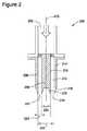
図2は、システム100とともに用いることができる、例示的なノズル200の断面図である。ノズル200はソースエンド202およびスプレイエンド204を含む。ノズル200は、ノズル200の縦軸210に沿ってアウターチューブと同軸状に整列したインナーロッド206を含む。環状流路212はアウターチューブ208の内表面214とインナーロッド206の外表面216との間に規定される。スプレイエンド204で、環状流路212は円形スリット218になる。1つの例示的な実施形態において、円形スリット218の内径220は2950μmであり、円形スリット218の外径222は3250μmであり、円形スリット218の幅224は150μmである。あるいは、円形スリット218は、ノズル200が本明細書で記載するように機能することができる任意の寸法を有してよい。 FIG. 2 is a cross-sectional view of an
操作中、シリンジポンプ102は圧力を噴霧液に印加し噴霧液はノズル200に向かって押され、ノズル200のソースエンド202で受けられる。噴霧液はそれから、環状流路212に均一に分配され、円形スリット218から薄い液体シートとして放出される。図2に示す1つの例示的な実施形態において、放出される液体シートは実質的に円筒形状である。 During operation, the
ノズル200はさらに、円形スリット218に近接する1つ以上のノッチ230を含む。本明細書で使用される“ノッチ”は、ノズル200のスプレイエンド204から伸びるノッチ230のような、ノズルのスプレイエンドから伸びて突き出た要素を意味する。例えば、このようなノッチは、このようなノッチで分けられたスプレイエンドの他の領域よりもさらにスプレイジェットの方向に伸びても、または突き出してもよい。1つの例示的な実施形態において、ノッチ230はインナーロッド206およびアウターチューブ208の両方の上に位置する。あるいは、ノッチ230はインナーロッド206またはアウターチューブ208のどちらかの上にのみ位置してもよい。高電圧源106がノズル200のスプレイエンド204に電圧を印加するとき、ノッチ230の形状と構成が、ノッチ230における電界の局所的な向上を容易にする。噴霧液が円形スリットに達するとき、噴霧液は環状流路212の形状により薄い液体シートとしてノズル200を出て行く。ノズル200のスプレイエンド204に印加される十分に高い電圧により、液体シートは複数のジェットへ分けられる。それぞれのノッチ230で局所的に高まった電界により、それぞれのジェットはノッチ230の1つに位置する。さらにスプレイエンド204に印加される十分に高い電圧により、安定したマルチジェット操作が達成され得る。いくつかの実施形態において、“安定したマルチジェット操作”は、噴霧液のジェットがノズル200上のノッチ230のそれぞれから放出されることを意味する。 The
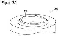
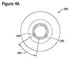
図3Aおよび図3Bは、図1のシステムとともに使用され得る例示的なノズル200の斜視図である。図4Aおよび図4Bは、図3Aおよび図3Bで示すノズル200の平面図である。図3Aおよび図4Aで示す実施形態は、6個のノッチ230を含み、図3Bおよび図4Bに示す実施形態は20個のノッチ230を含む。ノッチ230は円周方向の距離240ずつ、円周方向に互いに間隔を空けて配置している。いくつかの実施形態において、円周方向の距離240はノッチ230の寸法以上である。円周方向の距離240は、増大された電界領域を維持しながら、ノッチ230の数が最大限になるように選択される。すなわち、ノッチ230間の円周方向の距離240が小さすぎると、1つのノッチ230に発生する電界が近接するノッチ230に発生する電界を妨げるであろう。しかし、ノッチ230間の円周方向の距離240が増大すると、より少ないノッチ230がノズル200上に位置することができる。より少ないノッチ230によって、より少ないジェットが作られ、そしてノズル200の全体的な処理質量は減少する。 3A and 3B are perspective views of an
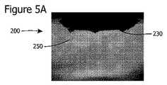
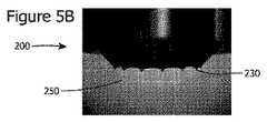
図5A〜図5Cは、噴霧液の複数のジェット250を作るノズル200の画像である。図5A、5Bおよび5Cのノズル200は、それぞれ6個、12個、20個のノッチ230を含む。 5A-5C are images of a
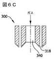
図6A〜図6Lは、図1のシステムに用いられ得る例示的なノズル300の断面図である。図6A〜図6Lに示す実施形態により実現されるように、ノズル300のいくつかの異なる構成はノズル300が本明細書で記載するように機能することができる。さらに、ノズル300の構成は、本明細書に具体的に記載されるものに限定するものでない。 6A-6L are cross-sectional views of an
図6A〜6Lのそれぞれのノズル300は、ソースエンド302およびスプレイエンド304を含む。さらに、それぞれのノズル300は、ノズル300の縦軸310に沿ってアウターチューブ308の同軸上に整列したインナーロッド306を含む。環状流路312は、アウターチューブ308の内表面314とインナーロッド306の外表面316との間に規定される。スプレイエンド304で、環状流路312は円形スリット318になる。さらに、スプレイエンド304でインナーロッド306はセンターピース(center piece)320を含み、アウターチューブ308は末端部分(またはエンドポーション、end portion)を含む。それぞれのノズル300はまた、図2に示すノッチ230と実質的に同様に機能する複数のノッチ330を含む。図6A〜図6Lの実施形態は、それぞれを以下に詳細に記載する。 Each
図6Aに示すノズル300の実施形態において、インナーロッド306とアウターチューブ308の両方ともがノッチ330をその上に含む。さらに、センターピース320は末端部分322に対して、凹部を有しておらず、または延在していない。図6Aに示す実施形態に操作する間、噴霧液は円形スリット318から放出される。 In the embodiment of the
図6Bに示すノズル300の実施形態において、アウターチューブ308だけがその上にノッチ330を含む。すなわち、インナーロッド306はノッチ330を含まない。さらに、センターピース320は末端部分322に対して凹部を有している。図6Bに示す実施形態の操作の間、噴霧液は円形スリット318から放出される。 In the embodiment of the
図6Cに示すノズル300の実施形態は、図6Cに示す実施形態がインナーロッド306通って規定される中央流路340を含むことを除いては、図6Aに示す実施形態と実質的に同様である。同様に、図6Dに示すノズル300の実施形態は、図6Dに示す実施形態がインナーロッド306を通って規定される中央流路340を含むことを除いては、図6Bに示す実施形態と実質的に同様である。図6Cおよび図6Dの実施形態において、安定化ガスは中央流路340から放出される。放出されるガスは、噴霧液が円形スリット318から放出されるときに、噴霧液の薄い液体シートの形状を維持することを容易にする。 The embodiment of the
図6Eおよび図6Fに示すノズル300の実施形態は、安定化ガスの代わりに安定化液体が中央流路340から放出されることを除いては、それぞれ図6Cおよび図6Dに示す実施形態と実質的に同様である。安定化ガスと同様に安定化液体は、噴霧液が円形スリット318から放出されるときに、噴霧液の薄い液体シートの形状を維持することを容易にする。図6Gに示すノズル300の実施形態は、センターピース320が末端部分322に対して延在していることを除いては、図6Fに示す実施形態と実質的に同様である。 The embodiment of the
図6Hおよび図6Iに示すノズル300の実施形態は、図6Hおよび図6Iの実施形態がさらに2つ目のアウターチューブ350を含むことを除いては、図6Cおよび図6Dに示す実施形態とそれぞれ実質的に同様である。2つ目のアウターチューブ350は、アウターチューブ308と同心状に整列し、2つ目の環状流路352は、アウターチューブ308の外表面354と2つ目のアウターチューブ350の内表面356との間に規定される。2つ目の環状流路352は、スプレイエンド304で2つ目の円形スリット360になる。 The embodiment of
図6Hおよび図6Iに示す実施形態において、2つ目のアウターチューブ350はその上にノッチ330を含む。1つ目の円形スリット318から放出される噴霧液に加えて、シース液(sheath liquid)が薄い(または細い、thin)液体シートの形状で2つ目の円形スリット360から放出される。噴霧液およびシース液(両方ともにノズル300から放出される)があることにより、粒子の封入(または被覆、encapsulation)が容易になり、ノズル300から作られる粒子は、シース液の粒子により封入された噴霧液の粒子および/または噴霧液の粒子により封入されたシース液の粒子を含む。図6Cおよび図6Dに示す実施形態と同様に、中央流路340から放出される安定化ガスは、噴霧液およびシース液の薄い液体シート形状を維持することを容易にする。あるいは、図6E〜図6Gと同様に、安定化ガスは中央流路340から放出されてもよい。図6Jに示す実施形態は、センターピース320が末端部分322に対して延在していることを除いては、図6Iに示す実施形態と実質的に同様である。 In the embodiment shown in FIGS. 6H and 6I, the second
図6Kに示すノズル300の実施形態は、図6Kに示す実施形態がさらに3つ目のアウターチューブ370を含むことを除いては、図6Hに示す実施形態と実質的に同様である。3つ目のアウターチューブ370は2つ目のアウターチューブ350と同心状に整列し、3つ目の環状流路372は2つ目のアウターチューブ350の外表面374と3つ目のアウターチューブ370の内表面376との間に規定される。3つ目の環状流路372はスプレイエンド304で円形スリット380になる。 The embodiment of
図6Kに示す実施形態において、3つ目のアウターチューブ370はその上にノッチ330を含む。1つ目の円形スリット318から放出される噴霧液および2つ目の円形スリット360から放出されるシース液に加えて、3つ目の円形スリット380から外周液(outer liquid)が薄い液体シートの形状で放出される。1つ目の円形スリット318、2つ目の円形スリット360および3つ目の円形スリット380からの液体の放出は、粒子の封入および多層粒子(multilayered particles)の製造を容易にする。図6Cおよび図6Dに示す実施形態と同様に、中央流路340から放出される安定化ガスは、放出される液体の薄い液体シート形状を維持することを容易にする。あるいは、図6E〜図6Gと同様に安定化液体が中央流路340から放出されてもよい。 In the embodiment shown in FIG. 6K, the third
円形スリット318、360および380が階段形状に構成され、アウターチューブ308が2つ目のアウターチューブ350に対して延在し、2つ目のアウターチューブ350が3つ目のアウターチューブ370に対して延在していることを除いては、図6Lに示す実施形態は図6Kに示す実施形態と実質的に同様である。階段形状により、図6Kに示す実施形態よりも低い電圧を図6Lに示す実施形態に印加して、安定したマルチジェット操作を達成してもよい。図6Lおよび図6Kに示す実施形態において、3つ目の円形スリット380から放出される外周液は、1つ目の円形スリット318から放出される噴霧液および2つ目の円形スリット360から放出されるシース液のうち少なくとも一方と同じ液体であってよい。あるいは、噴霧液、シース液および外周液は、全て異なる液体であってもよい。さらに、図6A〜図6Lに示す実施形態において、特定の流路がガスまたは液体を含むように示されるが、その他にも、ノズル300が本明細書に記載されるように機能できるように、任意の適切な流体(すなわち、ガス、液体)が任意の流路に供給されてもよい。 The
本明細書に記載するノズルを使用して複数の実験が実行された。以下の例では、イソプロパノールを噴霧液として選択し、硝酸をイオン添加剤として使用し、噴霧液の導電率を0.0079μS/cm(純イソプロパノール)から1,044μS/cmまで変化させた。噴霧液の導電率は導電率計(Orion 162A、Thermo Electron Corporation)により測定され、純イソプロパノールの電気抵抗率は研究室で作成した液体セルにより測定した。あるいは、当業者なら容易に理解するように、システム100が本明細書に記載するように機能することができる任意の噴霧液が使用されてよい。 Multiple experiments were performed using the nozzles described herein. In the following examples, isopropanol was selected as the spray solution, nitric acid was used as the ion additive, and the conductivity of the spray solution was varied from 0.0079 μS / cm (pure isopropanol) to 1,044 μS / cm. The conductivity of the spray solution was measured by a conductivity meter (Orion 162A, Thermo Electron Corporation), and the electrical resistivity of pure isopropanol was measured by a liquid cell prepared in the laboratory. Alternatively, any spray solution that allows the
図7は、異なる数のノッチを有するノズルに対する、安定したマルチジェット操作を確立ために印加する電圧を示すグラフである。グラフは、印加する電圧がノッチの数とともに増加することを実証する。また、安定したマルチジェット操作の確立のために印加する電圧も、供給する噴霧液の流量にわずかに比例するということもわかる。 FIG. 7 is a graph showing the voltage applied to establish a stable multi-jet operation for nozzles with different numbers of notches. The graph demonstrates that the applied voltage increases with the number of notches. It can also be seen that the voltage applied to establish a stable multi-jet operation is also slightly proportional to the flow rate of spray liquid supplied.
1つの実施例において、複数のジェット形成の発達(または変遷、evolution)を調べるため、スプレイ電流が測定され、印加する電圧が連続的に上昇しそれから低下させたときのジェットの数が数えられた。図8A〜図8Cは、6個、12個および20個のノッチを備えるノズルのそれぞれについてのスプレイ電流を、印加する電圧の関数として示すグラフである。スプレイ電流およびジェットの数は印加する電圧の上昇に伴って増加した。安定したマルチジェット操作(ジェットの数がノッチの数と同じである)は、十分に高い印加電圧で達成された。印加する電圧が低下すると、ジェットの数はそれに応じて減少した。さらに、グラフに示すように、ヒステリシス現象が観測された。 In one embodiment, in order to examine the evolution (or evolution) of multiple jet formations, the spray current was measured and the number of jets counted as the applied voltage was continuously increased and then decreased. . 8A-8C are graphs showing the spray current as a function of applied voltage for each of the nozzles with 6, 12, and 20 notches. The spray current and the number of jets increased with increasing applied voltage. Stable multi-jet operation (the number of jets is the same as the number of notches) was achieved with a sufficiently high applied voltage. As the applied voltage decreased, the number of jets decreased accordingly. Furthermore, as shown in the graph, a hysteresis phenomenon was observed.
他の実施例において、ノズルの質量処理能力を決定するために、様々な導電率の噴霧液を用いてノズル操作に対する最大液体流量(Qmax)を見出した。図9は、最大液体流量を噴霧液の導電率の関数として示したグラフである。グラフは、噴霧している液体の導電率が上昇するにつれてQmaxの値が著しく低下し、高い導電率を有する噴霧液であるほど、安定したマルチジェット操作を確立するのにより強い電界を一般的に使用するという事実に起因することを実証する。グラフはまた、ノッチの数が増加するにつれてQmaxが増加することも実証する。これは、ノッチの数が多量であるほどより多くのジェットを確立することができ、これにより噴霧液の流量および全体の質量処理能力が増加するためである。 In other examples, the maximum liquid flow rate (Qmax) for nozzle operation was found using different conductivity sprays to determine the nozzle mass throughput. FIG. 9 is a graph showing the maximum liquid flow rate as a function of spray conductivity. The graph shows that the value of Qmax decreases significantly as the conductivity of the liquid being sprayed increases, and the higher the conductivity, the stronger the electric field generally establishes more stable multi-jet operation. Demonstrate that it is due to the fact of using. The graph also demonstrates that Qmax increases as the number of notches increases. This is because the larger the number of notches, the more jets can be established, thereby increasing the spray liquid flow rate and the overall mass throughput.
図10は、既知の単一細管ノズルの最大液体流量に対する本明細書に記載の液体シートノズルの最大液体流量の比率を、噴霧液の導電率の関数として示すグラフである。この例において、単一細管ノズルの直径および液体シートノズルの円形スリットの幅は、ともに150μmである。図10のグラフ内に示すように、0.0079μS/cmの導電率の噴霧液を使用するとき、20個のノッチを備える液体シートノズルの最大液体流量、すなわちQmaxは、単一細管ノズルの最大流量よりも166倍大きかった。さらに、1,044μS/cmの導電率の噴霧液を使用するとき、20個のノッチを備える液体シートノズルの最大液体流量は、単一細管ノズルの最大液体流量よりも70倍大きかった。 FIG. 10 is a graph showing the ratio of the maximum liquid flow rate of the liquid sheet nozzle described herein to the maximum liquid flow rate of a known single capillary nozzle as a function of the conductivity of the spray liquid. In this example, the diameter of the single capillary tube nozzle and the width of the circular slit of the liquid sheet nozzle are both 150 μm. As shown in the graph of FIG. 10, when using a spray liquid with a conductivity of 0.0079 μS / cm, the maximum liquid flow rate of a liquid sheet nozzle with 20 notches, ie Qmax, is the maximum of a single capillary nozzle. It was 166 times larger than the flow rate. Further, when using a spray liquid with a conductivity of 1,044 μS / cm, the maximum liquid flow rate of the liquid sheet nozzle with 20 notches was 70 times greater than the maximum liquid flow rate of the single capillary nozzle.
とりわけ、20個のノッチを備える液体シートのノズルのQmaxの値は、20個の単一細管ノズル全体の液体流量の合計よりも、はるかに高い。この同様の現象は、6個および12個のノッチを備える液体シートノズルを使用しても観測される。これは、単一細管ノズルの既存の一次元配列および二次元配列に比べて、液体シートノズルが、広い範囲の導電率を有する噴霧液の質量処理能力を劇的に増加させる可能性を持っていることを意味する。 In particular, the value of Qmax for a liquid sheet nozzle with 20 notches is much higher than the sum of the liquid flow rates for the entire 20 single capillary nozzles. This same phenomenon is observed using a liquid sheet nozzle with 6 and 12 notches. This has the potential for a liquid sheet nozzle to dramatically increase the mass throughput of spray liquids with a wide range of conductivity compared to existing one-dimensional and two-dimensional arrays of single capillary nozzles. Means that
図11は、システム100で使用することができる代替ノズル500の平面図である。図12は、図11で示すノズル500の斜視図である。1つの実施形態において、ノズル500は第1プレート502、第2プレート504、ソースエンド506およびスプレイエンド508を含む。平面的な流路510は、第1プレート502と第2プレート504との間に規定される。平面的な流路510は、スプレイエンド508で線形のスリット512になる。操作中、噴霧液は線形のスリット512からのノズル500から放出される。ノズル200から放出される薄い液体シートが実質的に円筒形状であるのに対し、ノズル500から放出される薄い液体シートは実質的に平面状である。 FIG. 11 is a plan view of an
1つの例示的実施形態において、複数のノッチ514は、第1プレート502および第2プレート504の両方の上に位置し、互い違いとなる。あるいは、ノッチ514は、第1プレート502と第2プレート504のうちの1つの上にのみ位置してもよい。ノッチ514に電圧を印加することで、ノッチ514は薄い液体シートを複数のジェットに分離しやすくなり、実質的にノズル200のノッチ230と同様である。 In one exemplary embodiment, the plurality of
図1〜6L、11、12に示すノズルは、液体シートを放出するための例示的な手段を構成する。さらに、図2〜6L、11、12に示すノッチは、ノズルから放出された液体シートをマルチジェットに分離するための例示的な手段を構成する。さらに、図6C〜6Lに示すノズルは、ノズルから放出される液体シートの形状を維持するための例示的な手段を構成する。 The nozzles shown in FIGS. 1-6L, 11, and 12 constitute exemplary means for discharging a liquid sheet. Further, the notches shown in FIGS. 2-6L, 11, and 12 constitute exemplary means for separating the liquid sheet discharged from the nozzle into multi-jets. Furthermore, the nozzle shown in FIGS. 6C-6L constitutes an exemplary means for maintaining the shape of the liquid sheet discharged from the nozzle.
本明細書で具体的に記載される円筒形状および平面状のノズルに加えて、当業者なら容易に理解するように、本明細書で記載するようにシステム100を機能することができる任意のノズルの形状および/または構成が利用されてもよい。 In addition to the cylindrical and planar nozzles specifically described herein, any nozzle capable of functioning the
本明細書で記載する実施形態は、薄い液体シートを作り出すノズルを用いる電気流体力学的噴霧、すなわち電気スプレイ(ES)を可能にする。本明細書で記載の方法およびシステムはESシステムの質量処理能力を増加し、複数の単一細管ノズルを用いる既知のESシステムに比べて構成費用および製造費用を低減する。本明細書で記載するノズルは、噴霧液の薄い液体シートを放出するよう構成される環状および/または平面状のスリットを含む。薄い液体シートを複数のジェットに分離するように、またそのジェットを安定的な操作のために固定するように、複数のノッチが環状および/または平面上スリットに含まれる。すなわち、それぞれのノッチは、対応するジェットがノズルの周りに移動するのを防ぐことにより、その対応するジェットを固定し、実質的にその対応するジェットの位置を固定する。本明細書に記載するノズルに電圧が印加されるとき、これらのノッチの局所的な電界の増大が可能になる。さらに、本明細書に記載のノズルの安定的なマルチジェット操作は、様々な導電率を有する噴霧液の広範囲にわたって確立することができる。 The embodiments described herein allow for electrohydrodynamic spraying, or electrospray (ES), using a nozzle that creates a thin liquid sheet. The methods and systems described herein increase the mass throughput of the ES system and reduce configuration and manufacturing costs compared to known ES systems that use multiple single capillary nozzles. The nozzle described herein includes an annular and / or planar slit configured to discharge a thin liquid sheet of spray liquid. A plurality of notches are included in the annular and / or planar slits to separate the thin liquid sheet into a plurality of jets and to secure the jets for stable operation. That is, each notch fixes its corresponding jet and substantially fixes its corresponding jet position by preventing the corresponding jet from moving around the nozzle. When a voltage is applied to the nozzle described herein, it is possible to increase the local electric field at these notches. Furthermore, stable multi-jet operation of the nozzles described herein can be established over a wide range of spray liquids having various electrical conductivities.
さらに、複数列の(an arrays of)単一細管ノズルを用いる既知のESシステムに比べて、複数の液体流れの給水流路および/または分配流路は、本明細書に記載するノズルにはもはや必要でない。このように、本明細書に記載するノズルの構成概念および製作は既知のノズルよりも単純であり、ノズルの構成および/または配置の融通(または柔軟性、flexibility)を可能とする。 Further, compared to known ES systems that use an arrays of single capillary nozzles, multiple liquid flow feed and / or distribution channels are no longer present for the nozzles described herein. Not necessary. As such, the nozzle concepts and fabrication described herein are simpler than known nozzles and allow for flexibility in nozzle configuration and / or placement.
本明細書で記載するノズルを利用した実験を通して、ジェットの数および液体流量の両方ともが増加するにつれ、安定したマルチジェット操作を確立するために印加される電圧が増加することが実証された。さらに、本明細書で記載するノズルを通る最大の運用流量は、噴霧液の導電率の関数となった。さらに、いくつかの数のノッチを備える液体シートノズルの最大流量は、並べられた同数の単一細管ノズルの総流量合計よりも常に大きくなる。その結果、本明細書で記載する液体シートノズルは優れたES技術を可能とする。さらに、噴霧液の液体シートの形状は、既知の単一細管ノズルから放出されるコーンジェットとは対照的に、ノズルのデザインが、限定されるものではないが、環状および/または平面上のスリットを含む様々な幾何学形状を有することを可能にする。 Through experiments utilizing the nozzles described herein, it has been demonstrated that as both the number of jets and the liquid flow rate increase, the voltage applied to establish a stable multi-jet operation increases. Furthermore, the maximum operating flow rate through the nozzle described herein was a function of the spray liquid conductivity. Furthermore, the maximum flow rate of a liquid sheet nozzle with several numbers of notches is always greater than the total flow rate of the same number of aligned single capillary nozzles. As a result, the liquid sheet nozzle described herein allows for superior ES technology. Further, the shape of the liquid sheet of spray liquid is not limited to the design of the nozzle, in contrast to the cone jet emitted from a known single capillary nozzle, but is a slit on an annular and / or planar surface. It is possible to have various geometric shapes including.
本明細書で例示および記載する開示の実施形態での操作の遂行または実行(execution or performance)の順序は、特に明記しない限り、不可欠な要素ではない。すなわち、特に明記しない限り、任意の順序で操作を遂行してよく、開示の実施形態は、追加的な操作を、または本明細書に記載されるよりも少ない操作を含んでよい。例えば、別の操作の前、同時または後に特定の操作の実行または遂行をすることは、開示の態様の範囲内である。 The order of execution or performance of the disclosed embodiments illustrated and described herein is not an essential element unless otherwise stated. That is, unless otherwise specified, operations may be performed in any order, and disclosed embodiments may include additional operations or fewer operations than described herein. For example, it is within the scope of the disclosed aspects to perform or perform a particular operation before, simultaneously with, or after another operation.
開示の態様またはその実施形態の要素を取り上げるとき、冠詞“a”、“an”、“the”および“said”は、1つ以上の要素があることを意味することを目的とする。“〜を含む(comprising)”、“〜を含む(including)”および“〜を有する”は、包括的であり、記載された要素以外に付加的な要素があってもよいことを意味することを意図する。 When addressing elements of a disclosed aspect or embodiment thereof, the articles “a”, “an”, “the”, and “said” are intended to mean that there are one or more elements. “Comprising”, “including” and “having” are inclusive and mean that there may be additional elements other than the listed elements Intended.
ここに書かれた記載は、実施例を用いて最良の形態を含む開示を公開し(disclose the disclosure)、また当業者が、任意の装置またはシステムを作ること、および用いること、ならびに任意の取り込まれた方法を実行することを含む開示を実行することも可能である。本開示の特許を受けることが出来る範囲は、請求項によって規定され、また当業者が思いつく他の実施例を含んでもよい。このような他の実施例は、それらが、特許請求の範囲の文言と異ならない構造要素を有する場合、または特許請求の範囲の文言と均等な構造要素を有する場合、当該特許の範囲内であることが意図される。
なお、本発明は、以下の態様を含む。
・態様1
インナーロッドと、
前記インナーロッドと同心状に整列するアウターチューブと、
前記インナーロッドと前記アウターチューブとの間に規定され、ノズルのスプレイエンドに円形スリットを形成する環状流路と、
前記円形スリットに近接する前記インナーロッドと前記アウターチューブの、少なくとも一方の上に位置する少なくとも1つの帯電可能なノッチと、
を含む電気流体力学的噴霧のためのノズル。
・態様2
前記インナーロッドが、その内部を通って規定される中央流路を含む、態様1に記載のノズル。
・態様3
前記中央流路が、その内部を通る安定化ガスおよび安定化液体の少なくとも一方の流れを容易にするように構成される、態様2に記載のノズル。
・態様4
前記インナーロッドおよび前記アウターチューブと同心状に整列した最外部チューブを更に含み、前記アウターチューブと前記最外部チューブとの間に外側流路が規定される、態様1に記載のノズル。
・態様5
前記最外部チューブ上に位置する少なくとも1つの帯電可能なノッチを更に含む、態様4に記載のノズル。
・態様6
前記少なくとも1つの帯電可能なノッチが、前記インナーロッドと前記アウターチューブのどちらか一方にのみ位置する、態様1に記載のノズル。
・態様7
前記インナーロッドが前記ノズルのスプレイエンドにセンターピースを含み、前記アウターチューブが前記ノズルのスプレイエンドに末端部分を含み、前記センターピースが前記末端部分に対して凹部を有する、態様1に記載のノズル。
・態様8
前記インナーロッドが前記ノズルのスプレイエンドにセンターピースを含み、前記アウターチューブが前記ノズルのスプレイエンドに末端部分を含み、前記センターピースが前記末端部分に対して延在している、態様1に記載のノズル。
・態様9
前記少なくとも1つの帯電可能なノッチが複数のノッチを含み、前記複数のノッチが互いに間隔を空けて配置され、前記複数のノッチが帯電している時に、前記複数のノッチの1つにより作られる電界が前記複数のノッチの近接するノッチにより作られる電界によって妨げられない、態様1に記載のノズル。
・態様10
電気流体力学的噴霧のシステムであって、
ノズルであって、
ソースエンドと、
スプレイエンドと、
第1表面を含む第1部品と、
第2表面を含む第2部品と、
第1表面と第2表面との間に規定され、前記ノズルの前記スプレイエンドに出口スリ
ットを形成する流路と、
前記出口スリットに近接する前記第1部品および前記第2部品の少なくとも一方の上
に位置する、少なくとも1つの帯電可能なノッチと、
を含むノズルと、
前記ノズルに電気的につながれ、前記少なくとも1つの帯電可能なノッチに電圧を供給するように構成された電源と、
前記ノズルの前記ソースエンドで流体連通し、前記ノズルを通る噴霧液を押し出すように構成されるシリンジポンプと、
を含む電気流体力学的噴霧のシステム。
・態様11
前記第1部品が第1プレートを含み、前記第2部品が第2プレートを含み、前記流路が実質的に平面状である、態様10に記載のシステム。
・態様12
液体シートの放出のためのノズル手段をさらに含む、態様10に記載のシステム。
・態様13
前記ノズルから放出される液体シートを複数のジェットに分離するためのノッチ手段をさらに含む、態様10に記載のシステム。
・態様14
前記ノズルから放出される液体シートの形状を維持するための手段をさらに含む、態様10に記載のシステム。
・態様15
前記少なくとも1つの帯電可能なノッチが第1ノッチおよび第2ノッチを含み、前記第1ノッチおよび第2ノッチが互いに間隔を空けて配置され、電圧が前記第1ノッチおよび第2ノッチに供給されている時、前記第1ノッチによって作られる電界が前記第2ノッチによって作られる電界を妨げない、態様10に記載のシステム。
・態様16
電気流体力学的噴霧の方法であって、
ノズルであって、インナーロッド、前記インナーロッドと同心状に整列したアウターチューブ、前記インナーロッドと前記アウターチューブとの間に規定される環状流路、前記ノズルのスプレイエンドに円形スリットを形成する前記環状流路および前記円形スリットに近接する前記インナーロッドおよび前記アウターチューブの少なくとも一方の上に位置する複数のノッチ、を含むノズルを提供することと、
前記複数のノッチに電圧を供給することと、
前記ノズルの前記環状流路を介して噴霧液を送り出すことと、
を含む方法。
・態様17
前記インナーロッドが、その内部を通って規定される中央流路を含み、前記方法が、前記中央流路を通じて安定化ガスを送り出すことをさらに含む、態様16に記載の方法。
・態様18
前記インナーロッドが、その内部を通って規定される中央流路を含み、前記方法が、前記中央流路を通じて安定化液体を送り出すことをさらに含む、態様16に記載の方法。
・態様19
前記インナーロッドおよび前記アウターチューブと同心状に整列した最外部チューブを提供し、前記アウターチューブと前記最外部チューブとの間に外側流路が形成されることと、
前記外側流路を通してシース液を送り出すことと、
をさらに含む態様16に記載の方法。
・態様20
電圧の供給が、前記複数のノッチのそれぞれで噴霧液のジェットが形成されるような電圧の提供を含む、態様16に記載の方法。The written description herein uses examples to disclose the disclosure, including the best mode, and to enable any person skilled in the art to make and use any device or system, and any incorporation It is also possible to implement a disclosure that includes performing the method described. The patentable scope of the disclosure is defined by the claims, and may include other examples that occur to those skilled in the art. Such other embodiments are within the scope of the patent if they have structural elements that do not differ from the language of the claims, or if they have structural elements equivalent to the language of the claims. Is intended.
The present invention includes the following aspects.
・
An inner rod,
An outer tube aligned concentrically with the inner rod;
An annular channel defined between the inner rod and the outer tube and forming a circular slit at the spray end of the nozzle;
At least one chargeable notch located on at least one of the inner rod and the outer tube proximate to the circular slit;
Nozzle for electrohydrodynamic spraying including.
・
The nozzle according to
・ Aspect 3
The nozzle of
・
The nozzle according to
・
The nozzle of
・
The nozzle according to
・ Aspect 7
The nozzle according to
・
・
The at least one chargeable notch includes a plurality of notches, the plurality of notches being spaced apart from each other, and an electric field created by one of the plurality of notches when the plurality of notches are charged. A nozzle according to
An electrohydrodynamic spraying system comprising:
A nozzle,
The source end,
The spray end,
A first part including a first surface;
A second part including a second surface;
Defined between the first surface and the second surface, the outlet end of the nozzle at the spray end.
A flow path forming a gut;
On at least one of the first part and the second part adjacent to the exit slit
At least one chargeable notch located at
A nozzle including
A power source electrically coupled to the nozzle and configured to supply a voltage to the at least one chargeable notch;
A syringe pump in fluid communication at the source end of the nozzle and configured to push the spray liquid through the nozzle;
Including electrohydrodynamic spraying system.
11. The system of
The system of
The system of
The system of
The at least one chargeable notch includes a first notch and a second notch, the first notch and the second notch are spaced apart from each other, and a voltage is supplied to the first notch and the
A method of electrohydrodynamic spraying, comprising:
A nozzle, an inner rod, an outer tube concentrically aligned with the inner rod, an annular flow passage defined between the inner rod and the outer tube, and a circular slit formed in a spray end of the nozzle Providing a nozzle including a plurality of notches located on at least one of the inner channel and the outer tube proximate to the annular channel and the circular slit;
Supplying a voltage to the plurality of notches;
Sending out the spray liquid through the annular channel of the nozzle;
Including methods.
17. The method of
The method of
Aspect 19
Providing an outermost tube concentrically aligned with the inner rod and the outer tube, and forming an outer flow path between the outer tube and the outermost tube;
Pumping sheath fluid through the outer channel;
The method of
17. The method of
Claims (19)
Translated fromJapanese前記インナーロッドと同心状に整列し、かつ前記インナーロッドと離間しており、内表面を有するアウターチューブと、
前記インナーロッドと前記アウターチューブとの間に規定された環状流路であって、ノズルのスプレイエンドに円形スリットを形成しており、前記円形スリットは、前記インナーロッドの外表面と前記アウターチューブの内表面とによって規定される幅を有する、環状流路と、
前記円形スリットに近接する前記インナーロッドと前記アウターチューブの、少なくとも一方の上に位置する少なくとも1つの帯電可能なノッチと、
を含む電気流体力学的噴霧のためのノズル。An inner rodhaving an outer surface ;
An outer tubethat is concentrically alignedwith the inner rod and spaced from the inner rod, and has an inner surface ;
An annular flow path defined between the inner rod and the outer tube, wherein a circular slit is formedat a spray end of the nozzle, and the circular slit is formedbetween the outer surface of the inner rod and the outer tube. An annular channelhaving a width defined by the inner surface ;
At least one chargeable notch located on at least one of the inner rod and the outer tube proximate to the circular slit;
Nozzle for electrohydrodynamic spraying including.
ノズルであって、
ソースエンドと、
スプレイエンドと、
第1表面を含む第1部品と、
第2表面を含み、前記第2表面は前記第1部品の第1表面と離間しており、前記第1部品と同心状に整列している、第2部品と、
第1表面と第2表面との間に規定された流路であって、前記ノズルの前記スプレイエンドに出口スリットを形成しており、前記出口スリットは、前記第1部品の第1表面と、前記第2部品の第2表面とにより規定される幅を有する、流路と、
前記出口スリットに近接する前記第1部品および前記第2部品の少なくとも一方の上に位置する、少なくとも1つの帯電可能なノッチと、
を含むノズルと、
前記ノズルに電気的につながれ、前記少なくとも1つの帯電可能なノッチに電圧を供給するように構成された電源と、
前記ノズルの前記ソースエンドで流体連通し、前記ノズルを通る噴霧液を押し出すように構成されるシリンジポンプと、
を含む電気流体力学的噴霧のシステム。An electrohydrodynamic spraying system comprising:
A nozzle,
The source end,
The spray end,
A first part including a first surface;
Look including the secondsurface, the second surface are spaced apart from the first component of the first surface and aligned with the first part concentrically, a second component,
A flow path defined between a first surface and a second surface, wherein an outlet slit is formedin the spray end of the nozzle,and the outlet slit includes a first surface of the first component; A flow pathhaving a width defined by the second surface of the second part ;
At least one chargeable notch located on at least one of the first part and the second part proximate to the exit slit;
A nozzle including
A power source electrically coupled to the nozzle and configured to supply a voltage to the at least one chargeable notch;
A syringe pump in fluid communication at the source end of the nozzle and configured to push the spray liquid through the nozzle;
Including electrohydrodynamic spraying system.
ノズルであって、外表面を有するインナーロッド、前記インナーロッドと同心状に整列し、かつ前記インナーロッドと離間しており、内表面を有するアウターチューブ、前記インナーロッドと前記アウターチューブとの間に規定される環状流路、前記ノズルのスプレイエンドに円形スリットを形成しており、前記円形スリットは、前記インナーロッドの外表面と前記アウターチューブの内表面とによって規定される幅を有する、前記環状流路および前記円形スリットに近接する前記インナーロッドおよび前記アウターチューブの少なくとも一方の上に位置する複数のノッチ、を含むノズルを提供することと、
前記複数のノッチに電圧を供給することと、
前記ノズルの前記環状流路を介して噴霧液を送り出すことと、
を含む方法。A method of electrohydrodynamic spraying, comprising:
An inner rodhaving anouter surface, concentrically aligned withthe inner rod, and spaced apart from the inner rod; an outer tubehaving an inner surface; and between the inner rod and the outer tube A circular slit is formedin the defined annular flow path, the spray end of the nozzle,and the circular slit has a width defined by the outer surface of the inner rod and the inner surface of the outer tube. Providing a nozzle including a flow path and a plurality of notches located on at least one of the inner rod and the outer tube proximate to the circular slit;
Supplying a voltage to the plurality of notches;
Sending out the spray liquid through the annular channel of the nozzle;
Including methods.
前記外側流路を通してシース液を送り出すことと、
をさらに含む請求項15に記載の方法。Providing an outermost tube concentrically aligned with the inner rod and the outer tube, and forming an outer flow path between the outer tube and the outermost tube;
Pumping sheath fluid through the outer channel;
16. The method of claim15 , further comprising:
Applications Claiming Priority (3)
| Application Number | Priority Date | Filing Date | Title |
|---|---|---|---|
| US201161434249P | 2011-01-19 | 2011-01-19 | |
| US61/434,249 | 2011-01-19 | ||
| PCT/US2012/021723WO2012099961A2 (en) | 2011-01-19 | 2012-01-18 | Electrohydrodynamic atomization nozzle emitting a liquid sheet |
Publications (3)
| Publication Number | Publication Date |
|---|---|
| JP2014509251A JP2014509251A (en) | 2014-04-17 |
| JP2014509251A5 JP2014509251A5 (en) | 2015-03-05 |
| JP5961630B2true JP5961630B2 (en) | 2016-08-02 |
Family
ID=46516346
Family Applications (1)
| Application Number | Title | Priority Date | Filing Date |
|---|---|---|---|
| JP2013550564AExpired - Fee RelatedJP5961630B2 (en) | 2011-01-19 | 2012-01-18 | Electrohydrodynamic spray nozzle ejecting liquid sheet |
Country Status (5)
| Country | Link |
|---|---|
| US (3) | US10562048B2 (en) |
| EP (1) | EP2665559B1 (en) |
| JP (1) | JP5961630B2 (en) |
| CA (1) | CA2824930A1 (en) |
| WO (1) | WO2012099961A2 (en) |
Families Citing this family (23)
| Publication number | Priority date | Publication date | Assignee | Title |
|---|---|---|---|---|
| DE60135455D1 (en) | 2000-05-16 | 2008-10-02 | Univ Minnesota | IT OF MULTI-NOZZLE ARRANGEMENT |
| JP5961630B2 (en)* | 2011-01-19 | 2016-08-02 | ワシントン・ユニバーシティWashington University | Electrohydrodynamic spray nozzle ejecting liquid sheet |
| KR101388174B1 (en)* | 2012-08-09 | 2014-04-22 | 주식회사 엠엠테크 | Blade module and apparatus for treating of substrate |
| WO2016037074A1 (en) | 2014-09-04 | 2016-03-10 | Victory Innovations Company | Electrostatic fluid delivery system |
| US20160235677A1 (en) | 2014-11-25 | 2016-08-18 | Nanocopoeia, Llc. | Method of converting a crystalline compound to an amorphous compound, method of increasing the solubility of a crystalline compound in a biorelevant fluid, and nanoparticles that achieve supersaturation |
| US20160175881A1 (en) | 2014-12-22 | 2016-06-23 | Nanocopoeia, Llc | Electrospray methods, electrospray systems, and methods of forming crystalline particles |
| DK178701B1 (en)* | 2015-04-01 | 2016-11-21 | Spx Flow Tech Danmark As | A method and a system for monitoring spray nozzles in a spray drying or spray cooling chamber |
| JP6507028B2 (en)* | 2015-05-21 | 2019-04-24 | 東レエンジニアリング株式会社 | Electro spray device |
| JP6975150B2 (en) | 2015-12-21 | 2021-12-01 | ビクトリー・イノベイションズ・カンパニーVictory Innovations Company | Electrostatic fluid discharge backpack system |
| JP6880367B2 (en)* | 2016-11-28 | 2021-06-02 | アネスト岩田株式会社 | Electrostatic spraying device and electrostatic spraying method |
| US11141989B2 (en) | 2017-02-09 | 2021-10-12 | Virginia Commonwealth University | Dual channel jetting apparatus for 2D/3D electrohydrodynamic (EHD) printing |
| WO2018195400A1 (en)* | 2017-04-20 | 2018-10-25 | Victory Innovations Company | Electrostatic stem cell fluid delivery system |
| KR102084839B1 (en)* | 2018-01-10 | 2020-03-04 | 안상권 | injection syringe |
| WO2019229722A1 (en)* | 2018-06-01 | 2019-12-05 | Avectas Limited | Cell engineering platform |
| JP7186471B2 (en)* | 2019-07-31 | 2022-12-09 | 国立研究開発法人産業技術総合研究所 | Spray ionizer, analyzer and surface coating equipment |
| IL294928A (en) | 2020-01-24 | 2022-09-01 | Nanocopoeia Llc | Amorphous solid dispersions of dasatinib and uses thereof |
| JP2023513045A (en) | 2020-01-31 | 2023-03-30 | ナノコピーア リミテッド ライアビリティ カンパニー | Amorphous nilotinib microparticles and uses thereof |
| IL297776A (en) | 2020-04-30 | 2022-12-01 | Nanocopoeia Llc | Orally disintegrating tablet comprising amorphous solid dispersion of nilotinib |
| WO2022040446A1 (en) | 2020-08-19 | 2022-02-24 | Nanocopoeia, Llc | Amorphous pazopanib particles and pharmaceutical compositions thereof |
| WO2022115464A1 (en) | 2020-11-25 | 2022-06-02 | Nanocopoeia, Llc | Amorphous cabozantinib particles and uses thereof |
| US11980619B2 (en) | 2021-07-28 | 2024-05-14 | Nanocopoeia, Llc | Pharmaceutical compositions and crushable tablets including amorphous solid dispersions of dasatinib and uses |
| KR102549347B1 (en)* | 2022-10-06 | 2023-06-30 | 주식회사 솔탑 | Capillary Electrospray |
| KR102578631B1 (en)* | 2022-10-06 | 2023-09-15 | 주식회사 솔탑 | Circular electrospray |
Family Cites Families (31)
| Publication number | Priority date | Publication date | Assignee | Title |
|---|---|---|---|---|
| US2313994A (en)* | 1941-07-24 | 1943-03-16 | Akron Brass Mfg Company Inc | Spray nozzle |
| US2396449A (en)* | 1945-03-08 | 1946-03-12 | Spraying Systems Co | Spray nozzle |
| US3012733A (en)* | 1960-05-19 | 1961-12-12 | Akron Brass Mfg Company Inc | Nozzle |
| AU517923B2 (en)* | 1977-02-07 | 1981-09-03 | Ransburg Japan Ltd. | Rotary paint atomizing device |
| JPS5829150B2 (en)* | 1977-12-03 | 1983-06-21 | ナカヤ産業株式会社 | spray device |
| JPS5697566A (en)* | 1979-12-21 | 1981-08-06 | Ici Ltd | Vessel used for electrostatic atomizing and its holder |
| GB8504254D0 (en)* | 1985-02-19 | 1985-03-20 | Ici Plc | Spraying apparatus |
| DE3661121D1 (en)* | 1985-09-03 | 1988-12-15 | Sale Tilney Technology Plc | Electrostatic coating blade and method of electrostatic spraying |
| GB8609703D0 (en)* | 1986-04-21 | 1986-05-29 | Ici Plc | Electrostatic spraying |
| GB8614566D0 (en) | 1986-06-16 | 1986-07-23 | Ici Plc | Spraying |
| US4749125A (en)* | 1987-01-16 | 1988-06-07 | Terronics Development Corp. | Nozzle method and apparatus |
| GB9219636D0 (en)* | 1991-10-10 | 1992-10-28 | Ici Plc | Spraying of liquids |
| SE510215C2 (en)* | 1994-01-21 | 1999-05-03 | Electrolux Ab | Brake device for chainsaw |
| US6252129B1 (en)* | 1996-07-23 | 2001-06-26 | Electrosols, Ltd. | Dispensing device and method for forming material |
| US6433154B1 (en) | 1997-06-12 | 2002-08-13 | Bristol-Myers Squibb Company | Functional receptor/kinase chimera in yeast cells |
| AU5273401A (en) | 2000-04-18 | 2001-11-12 | Kang-Ho Ahn | Apparatus for manufacturing ultra-fine particles using electrospray device and method thereof |
| DE60135455D1 (en) | 2000-05-16 | 2008-10-02 | Univ Minnesota | IT OF MULTI-NOZZLE ARRANGEMENT |
| US7247338B2 (en) | 2001-05-16 | 2007-07-24 | Regents Of The University Of Minnesota | Coating medical devices |
| SE0300514D0 (en)* | 2003-02-26 | 2003-02-26 | Astrazeneca Ab | Powder generating apparatus and methods |
| WO2006089134A2 (en)* | 2005-02-15 | 2006-08-24 | Ehd Technology Group, Inc. | Apparatus and method for surface preparation using energetic and reactive cluster beams |
| DE102005016829A1 (en)* | 2005-04-12 | 2006-11-02 | Iff International Flavors & Fragrances | Method, nozzle and device for atomizing active substances contained in a liquid |
| US9108217B2 (en) | 2006-01-31 | 2015-08-18 | Nanocopoeia, Inc. | Nanoparticle coating of surfaces |
| US7951428B2 (en) | 2006-01-31 | 2011-05-31 | Regents Of The University Of Minnesota | Electrospray coating of objects |
| EP1988941A2 (en) | 2006-01-31 | 2008-11-12 | Nanocopoeia, Inc. | Nanoparticle coating of surfaces |
| CA2649413A1 (en)* | 2006-02-14 | 2007-08-23 | Battelle Memorial Institute | Dissociated discharge ehd sprayer with electric field shield |
| US20090277970A1 (en)* | 2006-06-26 | 2009-11-12 | Battelle Memorial Institute | Cartridge having self-actuating seal for a wetted lead screw |
| WO2008140663A2 (en)* | 2007-05-09 | 2008-11-20 | Nordson Corporation | Nozzle with internal filter |
| US8096264B2 (en)* | 2007-11-30 | 2012-01-17 | Illinois Tool Works Inc. | Repulsion ring |
| US8342120B2 (en) | 2008-03-14 | 2013-01-01 | The Board Of Trustees Of The University Of Illinois | Apparatuses and methods for applying one or more materials on one or more substrates |
| WO2010149197A1 (en)* | 2009-06-22 | 2010-12-29 | Abb Research Ltd | Nozzle device and spray applicator comprising the same |
| JP5961630B2 (en)* | 2011-01-19 | 2016-08-02 | ワシントン・ユニバーシティWashington University | Electrohydrodynamic spray nozzle ejecting liquid sheet |
- 2012
- 2012-01-18JPJP2013550564Apatent/JP5961630B2/ennot_activeExpired - Fee Related
- 2012-01-18EPEP12736538.5Apatent/EP2665559B1/ennot_activeNot-in-force
- 2012-01-18USUS13/979,260patent/US10562048B2/enactiveActive
- 2012-01-18WOPCT/US2012/021723patent/WO2012099961A2/enactiveApplication Filing
- 2012-01-18CACA2824930Apatent/CA2824930A1/ennot_activeAbandoned
- 2020
- 2020-02-13USUS16/789,865patent/US20200179963A1/ennot_activeAbandoned
- 2023
- 2023-08-18USUS18/235,560patent/US20230390791A1/ennot_activeAbandoned
Also Published As
| Publication number | Publication date |
|---|---|
| WO2012099961A2 (en) | 2012-07-26 |
| JP2014509251A (en) | 2014-04-17 |
| WO2012099961A3 (en) | 2012-10-26 |
| EP2665559B1 (en) | 2018-07-18 |
| CA2824930A1 (en) | 2012-07-26 |
| US20140158787A1 (en) | 2014-06-12 |
| EP2665559A2 (en) | 2013-11-27 |
| EP2665559A4 (en) | 2017-06-28 |
| US20200179963A1 (en) | 2020-06-11 |
| US10562048B2 (en) | 2020-02-18 |
| US20230390791A1 (en) | 2023-12-07 |
Similar Documents
| Publication | Publication Date | Title |
|---|---|---|
| JP5961630B2 (en) | Electrohydrodynamic spray nozzle ejecting liquid sheet | |
| Bocanegra et al. | Multiple electrosprays emitted from an array of holes | |
| KR101305768B1 (en) | Electrostatic spray printing apparatus | |
| JP2004500975A5 (en) | ||
| JP2010530795A (en) | Electrostatic spraying apparatus and electrostatic spraying method | |
| US12350698B2 (en) | Induction device for electrostatic spray nozzle assembly | |
| Hwang et al. | Motionless electrohydrodynamic (EHD) printing of biodegradable polymer micro patterns | |
| Tran et al. | Polymer-based electrospray device with multiple nozzles to minimize end effect phenomenon | |
| KR100947028B1 (en) | Non-conducting electrostatic spraying device and electrostatic spraying method | |
| CN110681505B (en) | An electrospray device | |
| Peng et al. | Design and evaluation of a linear nozzle array with double auxiliary electrodes for restraining cross-talk effect in parallel electrohydrodynamic jet printing | |
| WO2021157142A1 (en) | Spray ionization device | |
| JP5016505B2 (en) | Electrostatic atomizer | |
| WO2020241098A1 (en) | Spray ionization device, analysis device, and surface coating device | |
| US6964385B2 (en) | Method and apparatus for high throughput charge injection | |
| Kang et al. | Free-surface electrospray technique using a multi-hole array | |
| JP6264240B2 (en) | Spray application equipment | |
| WO2019102894A1 (en) | Electrostatic atomizer | |
| TWI238120B (en) | Electrostatic suction type fluid jet device | |
| JP7282346B2 (en) | Spray ionizer, analyzer and surface coating equipment | |
| KR101260414B1 (en) | Slit nozzle having a spray tip and method for thin layer coating using the same | |
| JP5833781B1 (en) | Electrostatic spraying equipment | |
| KR101400269B1 (en) | Electrospray nozzle and apparatus and method for electrospray using the same | |
| KR102549347B1 (en) | Capillary Electrospray | |
| WO2014030681A1 (en) | Electrostatic spray device |
Legal Events
| Date | Code | Title | Description |
|---|---|---|---|
| A521 | Request for written amendment filed | Free format text:JAPANESE INTERMEDIATE CODE: A523 Effective date:20150115 | |
| A621 | Written request for application examination | Free format text:JAPANESE INTERMEDIATE CODE: A621 Effective date:20150115 | |
| A977 | Report on retrieval | Free format text:JAPANESE INTERMEDIATE CODE: A971007 Effective date:20150820 | |
| A131 | Notification of reasons for refusal | Free format text:JAPANESE INTERMEDIATE CODE: A131 Effective date:20151006 | |
| A601 | Written request for extension of time | Free format text:JAPANESE INTERMEDIATE CODE: A601 Effective date:20160106 | |
| A521 | Request for written amendment filed | Free format text:JAPANESE INTERMEDIATE CODE: A523 Effective date:20160203 | |
| RD04 | Notification of resignation of power of attorney | Free format text:JAPANESE INTERMEDIATE CODE: A7424 Effective date:20160216 | |
| TRDD | Decision of grant or rejection written | ||
| A01 | Written decision to grant a patent or to grant a registration (utility model) | Free format text:JAPANESE INTERMEDIATE CODE: A01 Effective date:20160621 | |
| A61 | First payment of annual fees (during grant procedure) | Free format text:JAPANESE INTERMEDIATE CODE: A61 Effective date:20160627 | |
| R150 | Certificate of patent or registration of utility model | Ref document number:5961630 Country of ref document:JP Free format text:JAPANESE INTERMEDIATE CODE: R150 | |
| R250 | Receipt of annual fees | Free format text:JAPANESE INTERMEDIATE CODE: R250 | |
| R250 | Receipt of annual fees | Free format text:JAPANESE INTERMEDIATE CODE: R250 | |
| R250 | Receipt of annual fees | Free format text:JAPANESE INTERMEDIATE CODE: R250 | |
| R250 | Receipt of annual fees | Free format text:JAPANESE INTERMEDIATE CODE: R250 | |
| LAPS | Cancellation because of no payment of annual fees |