JP5959797B2 - Input device and control method of input device - Google Patents
Input device and control method of input deviceDownload PDFInfo
- Publication number
- JP5959797B2 JP5959797B2JP2010217621AJP2010217621AJP5959797B2JP 5959797 B2JP5959797 B2JP 5959797B2JP 2010217621 AJP2010217621 AJP 2010217621AJP 2010217621 AJP2010217621 AJP 2010217621AJP 5959797 B2JP5959797 B2JP 5959797B2
- Authority
- JP
- Japan
- Prior art keywords
- input device
- input
- user interface
- load
- tactile sensation
- Prior art date
- Legal status (The legal status is an assumption and is not a legal conclusion. Google has not performed a legal analysis and makes no representation as to the accuracy of the status listed.)
- Active
Links
Images


Classifications
- G—PHYSICS
- G06—COMPUTING OR CALCULATING; COUNTING
- G06F—ELECTRIC DIGITAL DATA PROCESSING
- G06F3/00—Input arrangements for transferring data to be processed into a form capable of being handled by the computer; Output arrangements for transferring data from processing unit to output unit, e.g. interface arrangements
- G06F3/01—Input arrangements or combined input and output arrangements for interaction between user and computer
- G06F3/03—Arrangements for converting the position or the displacement of a member into a coded form
- G06F3/041—Digitisers, e.g. for touch screens or touch pads, characterised by the transducing means
- G06F3/0416—Control or interface arrangements specially adapted for digitisers
- G—PHYSICS
- G06—COMPUTING OR CALCULATING; COUNTING
- G06F—ELECTRIC DIGITAL DATA PROCESSING
- G06F3/00—Input arrangements for transferring data to be processed into a form capable of being handled by the computer; Output arrangements for transferring data from processing unit to output unit, e.g. interface arrangements
- G06F3/01—Input arrangements or combined input and output arrangements for interaction between user and computer
- G06F3/016—Input arrangements with force or tactile feedback as computer generated output to the user
- G—PHYSICS
- G06—COMPUTING OR CALCULATING; COUNTING
- G06F—ELECTRIC DIGITAL DATA PROCESSING
- G06F3/00—Input arrangements for transferring data to be processed into a form capable of being handled by the computer; Output arrangements for transferring data from processing unit to output unit, e.g. interface arrangements
- G06F3/01—Input arrangements or combined input and output arrangements for interaction between user and computer
- G06F3/03—Arrangements for converting the position or the displacement of a member into a coded form
- G06F3/033—Pointing devices displaced or positioned by the user, e.g. mice, trackballs, pens or joysticks; Accessories therefor
- G06F3/038—Control and interface arrangements therefor, e.g. drivers or device-embedded control circuitry
- G—PHYSICS
- G06—COMPUTING OR CALCULATING; COUNTING
- G06F—ELECTRIC DIGITAL DATA PROCESSING
- G06F3/00—Input arrangements for transferring data to be processed into a form capable of being handled by the computer; Output arrangements for transferring data from processing unit to output unit, e.g. interface arrangements
- G06F3/01—Input arrangements or combined input and output arrangements for interaction between user and computer
- G06F3/03—Arrangements for converting the position or the displacement of a member into a coded form
- G06F3/041—Digitisers, e.g. for touch screens or touch pads, characterised by the transducing means
- G—PHYSICS
- G06—COMPUTING OR CALCULATING; COUNTING
- G06F—ELECTRIC DIGITAL DATA PROCESSING
- G06F3/00—Input arrangements for transferring data to be processed into a form capable of being handled by the computer; Output arrangements for transferring data from processing unit to output unit, e.g. interface arrangements
- G06F3/01—Input arrangements or combined input and output arrangements for interaction between user and computer
- G06F3/048—Interaction techniques based on graphical user interfaces [GUI]
- G06F3/0487—Interaction techniques based on graphical user interfaces [GUI] using specific features provided by the input device, e.g. functions controlled by the rotation of a mouse with dual sensing arrangements, or of the nature of the input device, e.g. tap gestures based on pressure sensed by a digitiser
- G06F3/0488—Interaction techniques based on graphical user interfaces [GUI] using specific features provided by the input device, e.g. functions controlled by the rotation of a mouse with dual sensing arrangements, or of the nature of the input device, e.g. tap gestures based on pressure sensed by a digitiser using a touch-screen or digitiser, e.g. input of commands through traced gestures
- G06F3/04883—Interaction techniques based on graphical user interfaces [GUI] using specific features provided by the input device, e.g. functions controlled by the rotation of a mouse with dual sensing arrangements, or of the nature of the input device, e.g. tap gestures based on pressure sensed by a digitiser using a touch-screen or digitiser, e.g. input of commands through traced gestures for inputting data by handwriting, e.g. gesture or text
- G—PHYSICS
- G06—COMPUTING OR CALCULATING; COUNTING
- G06F—ELECTRIC DIGITAL DATA PROCESSING
- G06F3/00—Input arrangements for transferring data to be processed into a form capable of being handled by the computer; Output arrangements for transferring data from processing unit to output unit, e.g. interface arrangements
- G06F3/01—Input arrangements or combined input and output arrangements for interaction between user and computer
- G06F3/048—Interaction techniques based on graphical user interfaces [GUI]
- G06F3/0487—Interaction techniques based on graphical user interfaces [GUI] using specific features provided by the input device, e.g. functions controlled by the rotation of a mouse with dual sensing arrangements, or of the nature of the input device, e.g. tap gestures based on pressure sensed by a digitiser
- G06F3/0488—Interaction techniques based on graphical user interfaces [GUI] using specific features provided by the input device, e.g. functions controlled by the rotation of a mouse with dual sensing arrangements, or of the nature of the input device, e.g. tap gestures based on pressure sensed by a digitiser using a touch-screen or digitiser, e.g. input of commands through traced gestures
- G06F3/04886—Interaction techniques based on graphical user interfaces [GUI] using specific features provided by the input device, e.g. functions controlled by the rotation of a mouse with dual sensing arrangements, or of the nature of the input device, e.g. tap gestures based on pressure sensed by a digitiser using a touch-screen or digitiser, e.g. input of commands through traced gestures by partitioning the display area of the touch-screen or the surface of the digitising tablet into independently controllable areas, e.g. virtual keyboards or menus
Landscapes
- Engineering & Computer Science (AREA)
- General Engineering & Computer Science (AREA)
- Theoretical Computer Science (AREA)
- Human Computer Interaction (AREA)
- Physics & Mathematics (AREA)
- General Physics & Mathematics (AREA)
- Position Input By Displaying (AREA)
- User Interface Of Digital Computer (AREA)
Description
Translated fromJapanese本発明は、タッチセンサを備える入力装置及び当該入力装置の制御方法に関するものである。 The present invention relates to an input device including a touch sensor and a method for controlling the input device.
近年、携帯電話等、ユーザによる入力操作を受け付ける操作部やスイッチ等の入力部として、タッチパネルやタッチスイッチ等のタッチセンサを備える携帯端末が広く使用されている。かかる携帯端末は、例えば図11に示すように、満員電車の中など、画面を目視して操作することが物理的及び心理的理由により困難な状況でも使用され得るものである。このような状況において、ユーザが画面を目視することなく勘を頼りに携帯端末を操作すると、タッチパネルにはボタンの凹凸などが存在しないため、誤ったキーに対して操作を行ってしまう可能性が高い。従来技術として、タッチパネル上に動的に操作用インタフェースを表示する方法については、タブレット触れたユーザの指の接触面積が閾値を超えた場合に、接触位置にソフトキーボードを表示する技術が存在する(例えば、特許文献1参照)。 In recent years, portable terminals including touch sensors such as touch panels and touch switches have been widely used as input units such as operation units and switches that accept input operations by users, such as mobile phones. For example, as shown in FIG. 11, such a portable terminal can be used even in a situation where it is difficult to visually operate the screen for physical and psychological reasons, such as in a crowded train. In such a situation, if the user operates the mobile terminal with his / her intuition without looking at the screen, the touch panel has no irregularities on the buttons, so there is a possibility that the user will operate on the wrong key. high. As a conventional technique, as a method for dynamically displaying an operation interface on a touch panel, there is a technique for displaying a soft keyboard at a contact position when a contact area of a user's finger touching a tablet exceeds a threshold ( For example, see Patent Document 1).
しかしながら、特許文献1の技術では、ユーザはソフトキーボードが表示された場所を漠然と知ることはできるが、ソフトキーボードの各キーの具体的な配置については知ることができない。即ち、表示されたソフトキーボードを用いて操作を行うためには、ユーザは画面を視認して各キーの位置を認識する必要があった。 However, in the technique of
したがって、かかる点に鑑みてなされた本発明の目的は、ユーザが画面を視認することなく操作可能なユーザインタフェースを生成することができる入力装置を提供することである。 Therefore, the objective of this invention made | formed in view of this point is providing the input device which can produce | generate the user interface which a user can operate without visually recognizing a screen.
上述した諸課題を解決すべく、第1の観点による入力装置は、
タッチ入力の入力位置を検出するタッチセンサと、
前記タッチセンサのタッチ面に対する押圧荷重を検出する荷重検出部と、
スリープモードにおいて、前記荷重検出部が所定の荷重基準を満たす押圧荷重を検出した場合、前記入力位置にホームポジションキーが配置されるように仮想的なユーザインタフェースを生成するように制御する制御部と、
を備えることを特徴とする。In order to solve the above-described problems, the input device according to the first aspect is
A touch sensor for detecting the input position of the touch input;
A load detection unit for detecting a pressing load on the touch surface of the touch sensor;
A control unit that controls to generate a virtual user interface so that a home position key is arranged at the input position when the load detection unit detects a pressing load that satisfies a predetermined load criterionin the sleep mode; ,
It is characterized by providing.
また、第2の観点による入力装置は、第1の観点による入力装置であって、
前記制御部は、前記押圧荷重に応じて、前記仮想的なユーザインタフェースを切り替える、ことを特徴とする。An input device according to the second aspect is the input device according to the first aspect,
The control unit switches the virtual user interface according to the pressing load.
また、第3の観点による入力装置は、第1又は第2の観点による入力装置であって、
前記タッチセンサのタッチ面を振動させる触感呈示部をさらに備え、
前記制御部は、前記仮想的なユーザインタフェースを生成した際に、押圧対象に対して触感を呈示するように前記触感呈示部を制御する、ことを特徴とする。The input device according to the third aspect is the input device according to the first or second aspect,
A tactile sensation providing unit that vibrates the touch surface of the touch sensor;
When the virtual user interface is generated, the control unit controls the tactile sensation providing unit so as to present a tactile sensation to the target to be pressed.
また、第4の観点による入力装置は、第1乃至第3の観点による入力装置であって、
前記制御部は、前記入力位置に前記ホームポジションキーが配置されるように前記仮想的なユーザインタフェースを生成することができない場合、前記押圧対象に対して触感を呈示するように前記触感呈示部を制御する、ことを特徴とする。An input device according to a fourth aspect is the input device according to the first to third aspects,
When the virtual user interface cannot be generated so that the home position key is arranged at the input position, the control unit is configured to display the tactile sensation providing unit so as to present a tactile sensation to the pressing target. It is characterized by controlling.
上述したように本発明の解決手段を装置として説明してきたが、本発明はこれらに実質的に相当する方法、プログラム、プログラムを記録した記憶媒体としても実現し得るものであり、本発明の範囲にはこれらも包含されるものと理解されたい。 As described above, the solution of the present invention has been described as an apparatus. However, the present invention can be realized as a method, a program, and a storage medium storing the program, which are substantially equivalent thereto, and the scope of the present invention. It should be understood that these are also included.
例えば、本発明を方法として実現させた第5の観点による入力装置の制御方法は、
タッチ入力の入力位置を検出するタッチセンサと、
前記タッチセンサのタッチ面に対する押圧荷重を検出する荷重検出部と、を備える入力装置の制御方法であって、
スリープモードにおいて、前記荷重検出部が所定の荷重基準を満たす押圧荷重を検出した場合、前記入力位置にホームポジションキーが配置されるように仮想的なユーザインタフェースを生成する、ことを特徴とする。
For example, the control method of the input device according to the fifthaspect obtained by implementing the present invention as method,
A touch sensor for detecting the input position of the touch input;
A load detection unit that detects a pressing load on the touch surface of the touch sensor, and a control method of an input device comprising:
In the sleep mode, when the load detection unit detects a pressing load that satisfies a predetermined load criterion, a virtual user interface is generated so that a home position key is arranged at the input position.
また、第6の観点による入力装置の制御方法は、第5の観点による入力装置の制御方法であって、
前記押圧荷重に応じて、前記仮想的なユーザインタフェースを切り替える、ことを特徴とする。An input device control method according to a sixth aspect is the input device control method according to the fifth aspect,
The virtual user interface is switched according to the pressing load.
また、第7の観点による入力装置の制御方法は、第5又は第6の観点による入力装置の制御方法であって、
前記入力装置は、前記タッチセンサのタッチ面を振動させる触感呈示部をさらに備え、
前記仮想的なユーザインタフェースを生成した際に、押圧対象に対して触感を呈示するように前記触感呈示部を制御する、ことを特徴とする。An input device control method according to a seventh aspect is the input device control method according to the fifth or sixth aspect,
The input device further includes a tactile sensation providing unit that vibrates the touch surface of the touch sensor,
When the virtual user interface is generated, the tactile sensation providing unit is controlled so as to present a tactile sensation to the pressed object.
また、第8の観点による入力装置の制御方法は、第5乃至第7の観点による入力装置の制御方法であって、
前記入力位置に前記ホームポジションキーが配置されるように前記仮想的なユーザインタフェースを生成することができない場合、前記押圧対象に対して触感を呈示するように前記触感呈示部を制御する、ことを特徴とする。An input device control method according to an eighth aspect is the input device control method according to the fifth to seventh aspects,
When the virtual user interface cannot be generated so that the home position key is arranged at the input position, the tactile sensation providing unit is controlled to present a tactile sensation with respect to the pressing target. Features.
本発明によれば、ユーザが画面を視認することなく操作可能なユーザインタフェースを生成することができる。 ADVANTAGE OF THE INVENTION According to this invention, the user interface which a user can operate without visually recognizing a screen can be produced | generated.
以降、諸図面を参照しながら、本発明の実施態様を詳細に説明する。以下の各実施の形態においては、本発明の入力装置の一例として、携帯電話やPDAなどのような携帯端末であってタッチパネルを備えているものを想定して説明する。しかしながら、本発明の入力装置は、これらの携帯端末に限定されるものではなく、例えば、ゲーム機、デジタルカメラ、ポータブルオーディオプレーヤ、ノートPC、ミニノートPCなどの種々の端末とすることができる。 Hereinafter, embodiments of the present invention will be described in detail with reference to the drawings. In each of the following embodiments, an example of an input device of the present invention will be described assuming a mobile terminal such as a mobile phone or a PDA that includes a touch panel. However, the input device of the present invention is not limited to these portable terminals, and can be various terminals such as a game machine, a digital camera, a portable audio player, a notebook PC, and a mini-notebook PC.
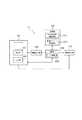
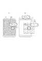
図1は、本実施の形態に係る入力装置10の内部構成を概略的に示す機能ブロック図である。図1に示すように、入力装置10は、タッチパネル101と、制御部104と、荷重検出部105と、触感呈示部106と、記憶部107とを備えている。本実施の形態では、タッチパネル101は、表示部102と、入力部103とを備えている。このタッチパネル101は、ユーザの入力を受け付ける入力部103を、表示部102の前面に重畳させて配設することにより構成する。 FIG. 1 is a functional block diagram schematically showing the internal configuration of the
タッチパネル101の表示部102は、例えば液晶ディスプレイ(LCD)または有機ELディスプレイなどで構成する。表示部102は、各アプリケーションに対応するグラフィカルユーザインタフェース(GUI)を表示する。かかるGUIには、例えば、ボタンやアイコン等の操作用オブジェクトが含まれる。表示部102の前面には、ユーザの指などによる入力を検出する入力部103が配設される。この入力部103はタッチセンサを構成するものであり、タッチセンサは、ユーザの指などがタッチセンサのタッチ面に触れたことを検出するセンサである。このタッチセンサは、例えば抵抗膜方式、静電容量方式、光学式等の公知の方式のもので構成される。入力部103は、ユーザの指などの入力を検出すると、入力位置の情報を制御部104に供給する。 The
荷重検出部105は、タッチセンサである入力部103のタッチ面に対する押圧荷重を検出するもので、例えば圧電素子、歪みゲージセンサなどを用いて構成する。荷重検出部105は、検出した押圧荷重を制御部104に供給する。 The
触感呈示部106は、タッチセンサである入力部103のタッチ面に振動を伝えるもので、例えば、圧電素子または超音波振動子などを用いて構成する。この触感呈示部106が振動することにより、入力部103を押圧しているユーザの指などに対して触感を呈示することができる。 The tactile
記憶部107は、各種アプリケーションの情報および閾値である各種荷重基準などを記憶するとともに、ワークメモリなどとしても機能する。記憶部107は、アプリケーションのGUI生成情報を記憶するGUI生成情報記憶領域1071と、呈示する触感パターンを記憶した触感パターン記憶領域1072とを有している。ここで、触感パターンとは、振動の仕方(周波数、位相、振動間隔、振動回数など)や振動の強さ(振幅など)等により規定されるものである。 The
制御部104は、CPU等のプロセッサにより構成されるものであり、入力装置10の各機能部をはじめとして入力装置10の全体を制御および管理する。制御部104は、触感パターン記憶領域1072から取得した触感パターンに基づき、ユーザの指等に触感を呈示するように触感呈示部106を制御する。また、制御部104は、アプリケーションのGUIや、アプリケーションの処理を制御するアプリ制御部1041を有している。アプリ制御部1041は、GUI生成情報記憶領域1071から取得した情報を基に、表示部102にアプリケーションに対応したGUIを表示する。 The
ここで、本実施の形態に係る入力装置10は、省電力機能であるスリープモードを備えるものである。即ち、制御部104は、ユーザから明示的なスリープモードへの移行指示がある場合や、ユーザからの操作が一定時間継続して行われない場合などに、入力装置10をスリープモードに移行させる。スリープモードでは、制御部104は、例えば表示部102の表示をOFFにする。なお、制御部104がスリープモードでOFFにする機能部は表示部102のみに限定されず、他の機能部をOFFにしてもよい。制御部104は、ユーザからの復帰操作があると、表示部102の表示をONにするなど、入力装置10をスリープモードから復帰させる。 Here, the
さらに、制御部104は、GUI生成情報記憶領域1071から取得したユーザインタフェース情報を基に、表示部102の表示とは関係なく機能する、仮想的なユーザインタフェースを生成することができる。仮想的なユーザインタフェースとは、表示部102に操作キー等が表示されていなくても、そこに操作キーが存在するものとして、ユーザからの操作を受け付けることができるユーザインタフェースを意味する。例えば、入力装置10がスリープモードであり表示部102の表示がOFFになっている場合でも、制御部104は、仮想的なユーザインタフェースを生成することによって、表示部の表示をONにすることなく、ユーザからの操作を受け付けることができる。特に、制御部104は、荷重検出部105が所定の荷重基準を満たす押圧荷重を検出した場合、ユーザの指等による入力位置にホームポジションキーが配置されるように仮想的なユーザインタフェースを生成する。ホームポジションキーとは、ユーザインタフェースの操作基点となる操作用オブジェクトである。 Furthermore, the
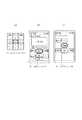
図2は、ホームポジションキーの一例を示す図である。図2(a)では、携帯電話の操作キーのうち、5キーがホームポジションキーとして設定されている。ユーザは、ホームポジションキーである5キーを基点とした各キーの位置を把握しておけば、ユーザの指の入力位置に5キーが配置されるように仮想的なユーザインタフェースが生成された場合、画面を視認することなく、5キーを基点として各キーの操作を行うことができる。図2(b)では、音楽アプリケーションにおいて、再生キーがホームポジションキーとして設定されている。また、図2(c)では、ユーザが独自に設定したユーザインタフェースにおいて、電源キーがホームポジションキーとして設定されている。図2(b)及び(c)の場合においても、ユーザは、ホームポジションキーを基点とした各キーの位置を把握しておけば、ユーザの指の入力位置にホームポジションキーが配置されるように仮想的なユーザインタフェースが生成された場合、画面を視認することなく、ホームポジションキーを基点として各キーの操作を行うことができる。 FIG. 2 is a diagram illustrating an example of the home position key. In FIG. 2A, among the operation keys of the mobile phone, 5 keys are set as home position keys. When the user knows the position of each key based on the home position key 5 key, a virtual user interface is generated so that the 5 keys are arranged at the input position of the user's finger Each key can be operated with the 5 key as a base point without visually recognizing the screen. In FIG. 2B, in the music application, the playback key is set as the home position key. In FIG. 2C, the power key is set as the home position key in the user interface uniquely set by the user. 2B and 2C, if the user knows the position of each key based on the home position key, the home position key is arranged at the input position of the user's finger. When a virtual user interface is generated, each key can be operated using the home position key as a base point without visually recognizing the screen.
図3は、ホームポジションキーを基点とした仮想的なユーザインタフェースの生成の一例を示す図である。図3(a)では入力装置10はスリープモードの状態であり、表示部102の表示はOFFになっている。ここで、図3(b)のように、ユーザが指Fによる入力を行うと、制御部104は、表示部102の表示をONにすることなく、入力位置にホームポジションキーが配置されるように仮想的なユーザインタフェースを生成する。このとき、制御部104は、触感呈示部106を制御し、仮想的なユーザインタフェースを生成した旨を触感(例えば「カチ、カチ」という2回の振動)によりユーザに通知することができる。図3(c)は、説明の便宜上、入力装置10において生成された仮想的なユーザインタフェースを図示するものである。図3(c)に示すとおり、入力装置10では、携帯電話操作キーのホームポジションキーである5キーが入力位置に配置されるように仮想的なユーザインタフェースが生成されている。ユーザは、ホームポジションキーである5キーを基点とした各キーの位置を把握しておけば、画面を視認することなく、5キーを基点として各キーの操作を行うことができる。 FIG. 3 is a diagram illustrating an example of generation of a virtual user interface based on the home position key. In FIG. 3A, the
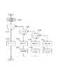
図4は、本実施の形態に係る入力装置10の動作を説明するフローチャートである。なお、これ以降、ホームポジションキーを基点とした仮想的なユーザインタフェースを適宜「ホームポジションUI」と称するものとする。図4のフローチャートに関し、処理開始時には入力装置10はスリープモードであるものとする。また、図5のように、記憶部107には、スリープモードからの復帰処理と、ホームポジションUI生成処理とを区別するために、スリープモードからの復帰処理用の荷重基準Aと、ホームポジションUI生成用の荷重基準B1、B2とが設定されている。ホームポジションUI生成用の荷重基準B1、B2には、それぞれ対応するアプリケーションと、ホームポジションUI生成時に呈示する触感パターンとが設定されている。 FIG. 4 is a flowchart for explaining the operation of the
入力装置10の処理は、ユーザの指等の押圧対象がタッチセンサである入力部103のタッチ面に触れることにより開始される。ユーザからの入力があると、制御部104は、入力部103から入力の位置情報である入力座標Zを取得し、荷重検出部105から入力部103のタッチ面に対する押圧荷重Xを取得する(ステップS101)。次に、制御部104は、押圧荷重Xがスリープモードからの復帰処理用の荷重基準A未満であるか判定する(ステップS103)。押圧荷重Xがスリープモードからの復帰処理用の荷重基準A未満である場合(ステップS103のYES)、制御部104は、スリープモードを維持したまま処理を終了する(ステップS104)。 The processing of the
押圧荷重Xがスリープモードからの復帰処理用の荷重基準A以上である場合(ステップS103のNO)、制御部104は、押圧荷重Xがスリープモードからの復帰処理用の荷重基準A以上かつホームポジションUI生成用の荷重基準B1未満であるか判定する(ステップS105)。押圧荷重Xがスリープモードからの復帰処理用の荷重基準A以上かつホームポジションUI生成用の荷重基準B1未満である場合(ステップS105のYES)、制御部104(アプリ制御部1041)は、荷重基準Aに対応する触感(例えば1回の振動)を呈示するように触感呈示部106を制御し(ステップS106)、表示部102の表示をONにするなどスリープモードからの復帰処理を行う(ステップS107)。 When the pressing load X is equal to or greater than the load reference A for the return processing from the sleep mode (NO in step S103), the
押圧荷重XがホームポジションUI生成用の荷重基準B1以上である場合(ステップS105のNO)、制御部104は、制御部104は、押圧荷重Xが荷重基準B1以上かつ荷重基準B2未満であるか判定する(ステップS108)。ここで、荷重基準B1及び荷重基準B2は共にホームポジションUI生成用の閾値であり、荷重基準毎に異なるアプリケーションのホームポジションUIが設定されていることを示すものである。すなわち、制御部104は、ユーザからの押圧荷重に応じて、生成するホームポジションUIを切り替えることができる。押圧荷重Xが荷重基準B1以上かつ荷重基準B2未満である場合(ステップS108のYES)、制御部104(アプリ制御部1041)は、荷重基準B1に対応した触感(例えば2回の振動)を呈示するように触感呈示部106を制御し(ステップS109)、荷重基準B1に対応したアプリケーション(例えば通話アプリケーション)のホームポジションUIを生成する(ステップS110)。このとき、制御部104は、表示部102の表示をONにして、ホームポジションUIを表示する必要はない。押圧荷重XがB2以上である場合(ステップS108のNO)、制御部104(アプリ制御部1041)は、荷重基準B2に対応した触感(例えば3回の振動)を呈示するように触感呈示部106を制御し(ステップS111)、荷重基準B2に対応したアプリケーション(例えば音楽アプリケーション)のホームポジションUIを生成する(ステップS110)。このときもまた、制御部104は、表示部102の表示をONにしてホームポジションUIを表示する必要はない。 When the pressing load X is greater than or equal to the load reference B1 for generating the home position UI (NO in step S105), the
図6は、ステップS110及びS112のホームポジションUI生成フローのフローチャートである。制御部104は、荷重閾値(B1、B2)に対応するアプリケーションを判定し(ステップS201)、GUI生成情報記憶領域1071から当該アプリケーションのユーザインタフェース情報を取得する(ステップS202)。制御部104は、入力座標Zにホームポジションキーを配置するようにホームポジションUIを生成することができるか判定する(ステップS203)。ホームポジションUIが生成可能である場合(ステップS203のYES)、制御部104は、ホームポジションUIを生成する(ステップS204)。ホームポジションUIが生成可能ではない場合(ステップS203のNO)、制御部104は、ユーザにホームポジションUIが生成できない旨を伝えるエラー触感を呈示するように制御部106を制御する(ステップS205)。 FIG. 6 is a flowchart of the home position UI generation flow in steps S110 and S112. The
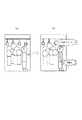
図7は、ホームポジションキーを基点とした仮想ユーザインタフェースの生成の一例を示す図である。図7(a)では入力装置10はスリープモードの状態であり、表示部102の表示はOFFになっている。ここで、図7(b)のように、ユーザが指Fによる入力を行うと、制御部104は、表示部102の表示をONにすることなく、入力位置にホームポジションキーが配置されるように仮想的なユーザインタフェースを生成する。このとき、制御部104は、触感呈示部106を制御し、仮想的なユーザインタフェースを生成した旨を触感(例えば「カチ、カチ、カチ」という3回の振動)によりユーザに通知することができる。図7(c)(d)は、説明の便宜上、入力装置10において生成された仮想的なユーザインタフェースを図示するものである。図7(c)に示すとおり、入力装置10では、音楽アプリケーションのホームポジションキーである再生キーが入力位置に配置されるように仮想的なユーザインタフェースが生成されている。ユーザは、ホームポジションキーである再生キーを基点とした各キーの位置を把握しておけば、画面を視認することなく、再生キーを基点として、例えば右隣のスキップキーの操作を行うことができる(図7(d))。このとき、制御部104は、触感呈示部106を制御し、スキップキーを操作した旨を触感(例えば「カチ」という1回の振動)によりユーザに通知することができる。 FIG. 7 is a diagram illustrating an example of generation of a virtual user interface based on the home position key. In FIG. 7A, the
図8は、ホームポジションキーを基点とした仮想ユーザインタフェースの生成の他の例を示す図である。図8(a)では入力装置10はスリープモードの状態であり、表示部102の表示はOFFになっている。ここで、図8(b)のように、ユーザが指Fによる入力を行うと、制御部104は、表示部102の表示をONにすることなく、入力位置にホームポジションキーが配置されるように仮想的なユーザインタフェースを生成する。図8(c)は、説明の便宜上、押下荷重B1に対応して生成された仮想的なユーザインタフェースを図示するものである。このとき、制御部104は、触感呈示部106を制御し、仮想的なユーザインタフェースを生成した旨を触感(例えば「カチ、カチ」という2回の振動)によりユーザに通知することができる。図8(c)に示すとおり、入力装置10では、携帯電話操作キーのホームポジションキーである5キーが入力位置に配置されるように仮想的なユーザインタフェースが生成されている。図8(d)は、説明の便宜上、押下荷重B2に対応して生成された仮想的なユーザインタフェースを図示するものである。このとき、制御部104は、触感呈示部106を制御し、仮想的なユーザインタフェースを生成した旨を触感(例えば「カチ、カチ、カチ」という3回の振動)によりユーザに通知することができる。図8(d)に示すとおり、入力装置10では、音楽アプリケーションのホームポジションキーである再生キーが入力位置に配置されるように仮想的なユーザインタフェースが生成されている。 FIG. 8 is a diagram illustrating another example of generation of a virtual user interface based on the home position key. In FIG. 8A, the
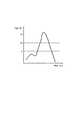
図9は、ホームポジションUIが生成できない場合のエラー触感通知の一例を示す図である。図9(a)のように、入力装置10に対してユーザが指Fによる入力を行うと、制御部104は、入力位置にホームポジションキーが配置されるように仮想的なユーザインタフェースの生成を試みる。しかし、この場合、ユーザの指Fによる入力位置が入力装置10の端部に行われているため、生成されるホームポジションUIは、図9(b)のように入力装置10(または、入力部103による入力検出)の範囲から外れてしまう。このため、制御部104は、ユーザに対してホームポジションUIを生成できない旨を通知するために、触感呈示部106を制御してエラー通知用の触感を呈示する。ここで、エラー通知用の触感は、例えば、「ブルブル」という継続した振動、または「プニ」というゲル触感が挙げられる。なお、ゲル触感を呈示する場合、制御部104は、触感呈示部106に駆動信号として、例えば、200Hz〜500Hz程度の正弦波信号を2〜3周期分印加する。 FIG. 9 is a diagram illustrating an example of an error tactile notification when the home position UI cannot be generated. As shown in FIG. 9A, when the user performs an input with the finger F on the
なお、制御部104は、生成されるホームポジションUIの一部分が入力装置10(または、入力部103による入力検出)の範囲から外れてしまった場合に、ユーザに対してホームポジションUIを生成できない旨を通知してもよい。また、例えば、ホームポジションUIに複数の操作用オブジェクトが含まれている場合、制御部104は、1つの操作用オブジェクトが入力装置10(または、入力部103による入力検出)の範囲から外れ、当該操作用オブジェクトの操作が不可能となった時点で、ユーザに対してホームポジションUIを生成できない旨を通知してもよい。 The
このように、本実施の形態によれば、制御部104は、荷重検出部106が所定の荷重基準を満たす押圧荷重を検出した場合、ユーザからの入力位置にホームポジションキーが配置されるように仮想的なユーザインタフェースを生成するように制御する。このため、ユーザは、ホームポジションキーを基点とした各キーの位置を把握しておけば、画面を視認することなく、ホームポジションキーを基点として各キーの操作を行うことができる。また、入力装置10がスリープモードである場合、表示部102の表示をONにして、ユーザインタフェースを表示部102に表示させる必要が無いため、電力消費を抑えることができる。 As described above, according to the present embodiment, when the
また、制御部104は、押圧荷重に応じて、仮想的なユーザインタフェースを切り替えることができる。このため、ユーザは、指等による入力の強弱を調整することにより、所望のアプリケーションに関する仮想的なユーザインタフェースを生成させることができる。 Moreover, the
また、制御部104は、仮想的なユーザインタフェースを生成した際に、ユーザの指等の押圧対象に対して触感を呈示するように触感呈示部106を制御する。このため、ユーザは、仮想的なユーザインタフェースが生成されたことを確実にすることができる。また、制御部104は、生成した仮想的なユーザインタフェースの種類に応じた触感を呈示するように触感呈示部106を制御することもできる。このため、ユーザは、触感を通して、どのアプリケーションに関する仮想的なユーザインタフェースが生成されたかを把握することができる。 In addition, when the virtual user interface is generated, the
また、制御部104は、入力位置にホームポジションキーが配置されるように仮想的なユーザインタフェースを生成することができない場合、ユーザの指等の押圧対象に対してエラー触感を呈示するように触感呈示部106を制御する。このため、ユーザは、エラー触感を通して、仮想的なユーザインタフェースが生成できない旨を把握することができる。 In addition, when the virtual user interface cannot be generated so that the home position key is arranged at the input position, the
本発明を諸図面や実施例に基づき説明してきたが、当業者であれば本開示に基づき種々の変形や修正を行うことが容易であることに注意されたい。従って、これらの変形や修正は本発明の範囲に含まれることに留意されたい。例えば、各機能部、各ステップなどに含まれる機能などは論理的に矛盾しないように再配置可能であり、複数の機能部やステップなどを1つに組み合わせたり、或いは分割したりすることが可能である。 Although the present invention has been described based on the drawings and examples, it should be noted that those skilled in the art can easily make various modifications and corrections based on the present disclosure. Therefore, it should be noted that these variations and modifications are included in the scope of the present invention. For example, the functions included in each functional unit, each step, etc. can be rearranged so that there is no logical contradiction, and a plurality of functional units, steps, etc. can be combined into one or divided. It is.
例えば、上記実施の形態では、入力装置10がスリープモードの状態を初期状態として説明を行ったが、本発明は、入力装置10の表示部102の表示がONである通常状態においても適用可能である。この場合、入力装置10の表示部102には、待ち受け画面や起動中のアプリケーションのGUIが表示されていることになるが、ホームポジションUI生成用の荷重基準として、当該GUI操作用の荷重基準より高い(又は低い)荷重基準を設定することにより、当該GUIの操作とホームポジションUI生成とを区別することができる。また、待ち受け画面等のGUIが表示部102に表示されている場合に、アイコンや操作キー等の操作用オブジェクト以外の領域に所定の荷重基準を満たす押圧があった場合に、ホームポジションUIを生成するように設定することもできる。このように、待ち受け画面等のGUIが表示部102に表示されている場合でも、制御部104は、ユーザからの押圧荷重に応じたホームポジションUIを生成することができるため、ユーザは画面を視認することなく入力装置10の操作を行うことが可能になる。 For example, in the above embodiment, the
また、上記実施の形態では、仮想ユーザインタフェースは表示部102に表示されないものとして説明を行ったが、制御部104は、生成した仮想的なユーザインタフェースを表示部102に表示させることもできる。この場合、本発明における「仮想的なユーザインタフェース」は、「表示部102に操作キー等が表示されている場合にのみユーザからの操作を受け付けることができる」ものとすることもできる。即ち、本発明における「仮想的なユーザインタフェース」とは、表示部102に表示される通常のグラフィカルユーザインタフェースをも含むものである。この場合でも、ユーザは、ホームポジションキーを基点とした各キーの位置を把握しておけば、画面を視認することなく、ホームポジションキーを基点として各キーの操作を行うことができる。また、ユーザが画面を視認できるような状況では、ユーザはグラフィカルユーザインタフェースを確認して操作を行うことができるため有利である。 In the above embodiment, the virtual user interface has been described as not being displayed on the
また、上記実施の形態では、図4に示すフローにおいて、ステップS105の判定の後(YESの場合)にステップS106の触感呈示が行われ、ステップS108の判定の後(YESの場合)にステップS109の触感呈示が行われているが、制御部104は、ステップS106の触感呈示をステップS103の判定の後に行い、ステップS109の触感呈示をステップS105の判定の後に行うように触感呈示部106を制御することもできる。これにより、ユーザには、押圧荷重が所定の荷重基準を超えた時点で対応する触感が呈示されるため、ユーザは現在の押圧荷重を認識することができる。なおこの場合、制御部104は、ステップS107の通常復帰操作や、ステップS110のホームポジションUI生成の際に、再度ユーザに対して触感を呈示するように触感呈示部106を制御することもできる。 Further, in the above embodiment, in the flow shown in FIG. 4, after the determination in step S105 (in the case of YES), the tactile sensation is presented in step S106, and after the determination in step S108 (in the case of YES), step S109 is performed. However, the
なお、図4に示すフローにおいて、ステップS103においてYESと判定される「押圧荷重Xが荷重基準A未満である場合」とは、例えば、「押圧荷重Xが、荷重基準A以上になることなく0になった場合」が挙げられる。 In the flow shown in FIG. 4, “when the pressing load X is less than the load reference A” determined to be YES in step S103 is, for example, “the pressing load X is 0 without exceeding the load reference A”. "When it becomes".
また、ステップS105においてYESと判定される「押圧荷重Xが荷重基準A以上かつ荷重基準B1未満である場合」とは、例えば「押圧荷重Xが、荷重基準A以上になったのちに、荷重基準B1以上になることなく荷重基準A未満になった場合」、「押圧荷重Xが、荷重基準A以上になったのちに、荷重基準B1以上になることなく押圧荷重が減少した場合」又は、「押圧荷重Xが、荷重基準A以上になったのちに、荷重基準B1以上になることなく、荷重基準A以上になった状態で所定時間を経過した場合」が挙げられる。ステップS108においてYESと判定される場合も、荷重基準B1、B2について同様の判定が行われる。 In addition, “when the pressing load X is equal to or greater than the load criterion A and less than the load criterion B1” determined as YES in step S105 is, for example, “after the pressing load X becomes equal to or greater than the load criterion A, "When the load becomes less than the load reference A without becoming more than B1," "After the pressure load X becomes more than the load reference A, the pressure load decreases without becoming more than the load reference B1," or " After the pressing load X becomes equal to or greater than the load reference A, the predetermined time elapses in a state where the load load A exceeds the load reference B1 without exceeding the load reference B1 ”. Even when it is determined as YES in step S108, the same determination is performed for the load standards B1 and B2.
また、ステップS103においてNOと判定される「押圧荷重Xが荷重基準A以上である場合」とは、「押圧荷重Xが荷重基準A以上になった場合」が挙げられる。ステップS105及びステップS108においてYESと判定される場合も、それぞれ、荷重基準B1、B2について同様の判定が行われる。 Further, “when the pressing load X is equal to or greater than the load reference A” determined as NO in Step S103 includes “when the pressing load X is equal to or greater than the load criterion A”. Even when YES is determined in step S105 and step S108, the same determination is performed for the load standards B1 and B2, respectively.
また、ホームポジションキーは、アプリケーション毎に固定的に設定されるものではなく、ユーザが任意のキーをホームポジションキーとして設定することができる。図10は、ユーザによるホームポジションキーの設定画面の一例を示す図である。図10(a)はホームポジションキーの設定画面であり、図10(b)は設定したホームポジションキーのプレビュー画面を示している。図10(a)において、ユーザは、ユーザからの押圧荷重と対応付けて、生成するホームポジションUI(アプリケーション)と、ホームポジションキーとを設定することができる。図10(a)の例では、2番目の荷重基準に待ち受け画面が対応付けられ、電源ボタンがホームポジションキーに設定されている。また、3番目の荷重基準に音楽アプリケーションが対応付けられ、再生/停止キーがホームポジションキーに設定されている。ユーザは、図10(b)に示すプレビュー画面を参照することにより、現在選択されているホームポジションキーや、周囲に配置されている各キーの位置を確認することができる。 The home position key is not fixedly set for each application, and the user can set an arbitrary key as the home position key. FIG. 10 is a diagram illustrating an example of a home position key setting screen by the user. FIG. 10A shows a home position key setting screen, and FIG. 10B shows a preview screen of the set home position key. In FIG. 10A, the user can set a home position UI (application) to be generated and a home position key in association with the pressing load from the user. In the example of FIG. 10A, the standby screen is associated with the second load reference, and the power button is set as the home position key. The music application is associated with the third load standard, and the play / stop key is set as the home position key. By referring to the preview screen shown in FIG. 10B, the user can confirm the position of the currently selected home position key and each of the keys arranged around.
10 入力装置
101 タッチパネル
102 表示部
103 入力部
104 制御部
1041 アプリ制御部
105 荷重検出部
106 触感呈示部
107 記憶部
1071 GUI生成情報記憶領域
1072 触感パターン記憶領域DESCRIPTION OF
Claims (8)
Translated fromJapanese前記タッチセンサのタッチ面に対する押圧荷重を検出する荷重検出部と、
スリープモードにおいて、前記荷重検出部が所定の荷重基準を満たす押圧荷重を検出した場合、前記入力位置にホームポジションキーが配置されるように仮想的なユーザインタフェースを生成するように制御する制御部と、
を備えることを特徴とする入力装置。A touch sensor for detecting the input position of the touch input;
A load detection unit for detecting a pressing load on the touch surface of the touch sensor;
A control unit that controls to generate a virtual user interface so that a home position key is arranged at the input position when the load detection unit detects a pressing load that satisfies a predetermined load criterionin the sleep mode; ,
An input device comprising:
前記制御部は、前記押圧荷重に応じて、前記仮想的なユーザインタフェースを切り替える、ことを特徴とする入力装置。The input device according to claim 1,
The control device switches the virtual user interface according to the pressing load.
前記タッチセンサのタッチ面を振動させる触感呈示部をさらに備え、
前記制御部は、前記仮想的なユーザインタフェースを生成した際に、押圧対象に対して触感を呈示するように前記触感呈示部を制御する、ことを特徴とする入力装置。The input device according to claim 1 or 2,
A tactile sensation providing unit that vibrates the touch surface of the touch sensor;
The said control part controls the said tactile sense presentation part so that a tactile sensation may be shown with respect to a press target, when the said virtual user interface is produced | generated.
前記制御部は、前記入力位置に前記ホームポジションキーが配置されるように前記仮想的なユーザインタフェースを生成することができない場合、前記押圧対象に対して触感を呈示するように前記触感呈示部を制御する、ことを特徴とする入力装置。The input device according to any one of claims 1 to 3,
When the virtual user interface cannot be generated so that the home position key is arranged at the input position, the control unit is configured to display the tactile sensation providing unit so as to present a tactile sensation to the pressing target. An input device characterized by controlling.
前記タッチセンサのタッチ面に対する押圧荷重を検出する荷重検出部と、を備える入力装置の制御方法であって、
スリープモードにおいて、前記荷重検出部が所定の荷重基準を満たす押圧荷重を検出した場合、前記入力位置にホームポジションキーが配置されるように仮想的なユーザインタフェースを生成する、ことを特徴とする入力装置の制御方法。A touch sensor for detecting the input position of the touch input;
A load detection unit that detects a pressing load on the touch surface of the touch sensor, and a control method of an input device comprising:
An input characterized by generating a virtual user interface so that a home position key is arranged at the input position when the load detection unit detects a pressing load that satisfies a predetermined load standardin the sleep mode. Control method of the device.
前記押圧荷重に応じて、前記仮想的なユーザインタフェースを切り替える、ことを特徴とする入力装置の制御方法。A control method for an input device according to claim 5,
A method for controlling an input device, wherein the virtual user interface is switched according to the pressing load.
前記入力装置は、前記タッチセンサのタッチ面を振動させる触感呈示部をさらに備え、
前記仮想的なユーザインタフェースを生成した際に、押圧対象に対して触感を呈示するように前記触感呈示部を制御する、ことを特徴とする入力装置の制御方法。The input device according to claim 5 or 6,
The input device further includes a tactile sensation providing unit that vibrates the touch surface of the touch sensor,
A control method for an input device, characterized in that, when the virtual user interface is generated, the tactile sensation providing unit is controlled so as to present a tactile sensation to a pressed object.
前記入力位置に前記ホームポジションキーが配置されるように前記仮想的なユーザインタフェースを生成することができない場合、前記押圧対象に対して触感を呈示するように前記触感呈示部を制御する、ことを特徴とする入力装置の制御方法。A control method for an input device according to any one of claims 5 to 7,
When the virtual user interface cannot be generated so that the home position key is arranged at the input position, the tactile sensation providing unit is controlled to present a tactile sensation with respect to the pressing target. A method for controlling an input device.
Priority Applications (3)
| Application Number | Priority Date | Filing Date | Title |
|---|---|---|---|
| JP2010217621AJP5959797B2 (en) | 2010-09-28 | 2010-09-28 | Input device and control method of input device |
| PCT/JP2011/005480WO2012042876A1 (en) | 2010-09-28 | 2011-09-28 | Input device, and control method for input device |
| US13/876,461US9035897B2 (en) | 2010-09-28 | 2011-09-28 | Input apparatus and control method of input apparatus |
Applications Claiming Priority (1)
| Application Number | Priority Date | Filing Date | Title |
|---|---|---|---|
| JP2010217621AJP5959797B2 (en) | 2010-09-28 | 2010-09-28 | Input device and control method of input device |
Publications (2)
| Publication Number | Publication Date |
|---|---|
| JP2012073785A JP2012073785A (en) | 2012-04-12 |
| JP5959797B2true JP5959797B2 (en) | 2016-08-02 |
Family
ID=45892365
Family Applications (1)
| Application Number | Title | Priority Date | Filing Date |
|---|---|---|---|
| JP2010217621AActiveJP5959797B2 (en) | 2010-09-28 | 2010-09-28 | Input device and control method of input device |
Country Status (3)
| Country | Link |
|---|---|
| US (1) | US9035897B2 (en) |
| JP (1) | JP5959797B2 (en) |
| WO (1) | WO2012042876A1 (en) |
Families Citing this family (43)
| Publication number | Priority date | Publication date | Assignee | Title |
|---|---|---|---|---|
| US9417754B2 (en) | 2011-08-05 | 2016-08-16 | P4tents1, LLC | User interface system, method, and computer program product |
| JP5777217B2 (en)* | 2012-01-26 | 2015-09-09 | Kddi株式会社 | User interface device capable of starting operation mode by pressing operation, operation mode starting method and program |
| WO2013169843A1 (en) | 2012-05-09 | 2013-11-14 | Yknots Industries Llc | Device, method, and graphical user interface for manipulating framed graphical objects |
| WO2013169842A2 (en) | 2012-05-09 | 2013-11-14 | Yknots Industries Llc | Device, method, and graphical user interface for selecting object within a group of objects |
| CN108958550B (en) | 2012-05-09 | 2021-11-12 | 苹果公司 | Device, method and graphical user interface for displaying additional information in response to user contact |
| CN108241465B (en) | 2012-05-09 | 2021-03-09 | 苹果公司 | Method and apparatus for providing haptic feedback for operations performed in a user interface |
| EP2847662B1 (en) | 2012-05-09 | 2020-02-19 | Apple Inc. | Device, method, and graphical user interface for providing feedback for changing activation states of a user interface object |
| WO2013169849A2 (en) | 2012-05-09 | 2013-11-14 | Industries Llc Yknots | Device, method, and graphical user interface for displaying user interface objects corresponding to an application |
| WO2013169865A2 (en) | 2012-05-09 | 2013-11-14 | Yknots Industries Llc | Device, method, and graphical user interface for moving a user interface object based on an intensity of a press input |
| HK1208275A1 (en) | 2012-05-09 | 2016-02-26 | 苹果公司 | Device, method, and graphical user interface for moving and dropping a user interface object |
| EP3410287B1 (en) | 2012-05-09 | 2022-08-17 | Apple Inc. | Device, method, and graphical user interface for selecting user interface objects |
| AU2013259630B2 (en) | 2012-05-09 | 2016-07-07 | Apple Inc. | Device, method, and graphical user interface for transitioning between display states in response to gesture |
| KR102091597B1 (en)* | 2012-09-24 | 2020-03-20 | 엘지전자 주식회사 | Portable device and controlling method thereof |
| KR102001332B1 (en) | 2012-12-29 | 2019-07-17 | 애플 인크. | Device, method, and graphical user interface for determining whether to scroll or select contents |
| WO2014105279A1 (en) | 2012-12-29 | 2014-07-03 | Yknots Industries Llc | Device, method, and graphical user interface for switching between user interfaces |
| CN105264479B (en)* | 2012-12-29 | 2018-12-25 | 苹果公司 | Apparatus, method and graphical user interface for navigating a user interface hierarchy |
| CN105144057B (en) | 2012-12-29 | 2019-05-17 | 苹果公司 | For moving the equipment, method and graphic user interface of cursor according to the cosmetic variation of the control icon with simulation three-dimensional feature |
| JP6851197B2 (en)* | 2013-05-30 | 2021-03-31 | ティーケー ホールディングス インク.Tk Holdings Inc. | Multidimensional trackpad |
| US9798372B2 (en)* | 2013-06-03 | 2017-10-24 | Qualcomm Incorporated | Devices and methods of sensing combined ultrasonic and infrared signal |
| US9454251B1 (en) | 2013-06-26 | 2016-09-27 | Google Inc. | Methods, systems, and media for controlling a remote device using a touch screen of a mobile device in a display inhibited state |
| WO2015054362A1 (en) | 2013-10-08 | 2015-04-16 | Tk Holdings Inc. | Force-based touch interface with ingrated multi-sensory feedback |
| US9632664B2 (en) | 2015-03-08 | 2017-04-25 | Apple Inc. | Devices, methods, and graphical user interfaces for manipulating user interface objects with visual and/or haptic feedback |
| US10095396B2 (en) | 2015-03-08 | 2018-10-09 | Apple Inc. | Devices, methods, and graphical user interfaces for interacting with a control object while dragging another object |
| US9639184B2 (en) | 2015-03-19 | 2017-05-02 | Apple Inc. | Touch input cursor manipulation |
| US20170045981A1 (en) | 2015-08-10 | 2017-02-16 | Apple Inc. | Devices and Methods for Processing Touch Inputs Based on Their Intensities |
| AT517172B1 (en)* | 2015-04-23 | 2018-07-15 | Ing Mag Fh Andreas Tragenreif | Input element for electronic devices |
| US10200598B2 (en) | 2015-06-07 | 2019-02-05 | Apple Inc. | Devices and methods for capturing and interacting with enhanced digital images |
| US9830048B2 (en) | 2015-06-07 | 2017-11-28 | Apple Inc. | Devices and methods for processing touch inputs with instructions in a web page |
| US9860451B2 (en) | 2015-06-07 | 2018-01-02 | Apple Inc. | Devices and methods for capturing and interacting with enhanced digital images |
| US9891811B2 (en) | 2015-06-07 | 2018-02-13 | Apple Inc. | Devices and methods for navigating between user interfaces |
| US9880735B2 (en) | 2015-08-10 | 2018-01-30 | Apple Inc. | Devices, methods, and graphical user interfaces for manipulating user interface objects with visual and/or haptic feedback |
| US10235035B2 (en) | 2015-08-10 | 2019-03-19 | Apple Inc. | Devices, methods, and graphical user interfaces for content navigation and manipulation |
| CN105491200B (en)* | 2016-01-07 | 2018-11-30 | 珠海格力电器股份有限公司 | Multifunctional key combination structure and smart phone |
| KR20170124693A (en)* | 2016-05-03 | 2017-11-13 | 주식회사 하이딥 | Displaying method of touch input device |
| JP2018005274A (en)* | 2016-06-27 | 2018-01-11 | ソニー株式会社 | Information processing device, information processing method, and program |
| KR102535737B1 (en) | 2016-08-03 | 2023-05-24 | 삼성전자주식회사 | Electric device comprising force sensor |
| US10650621B1 (en) | 2016-09-13 | 2020-05-12 | Iocurrents, Inc. | Interfacing with a vehicular controller area network |
| KR102364429B1 (en)* | 2017-05-17 | 2022-02-17 | 삼성전자주식회사 | Method for displaying contents and electronic device thereof |
| KR20190003085A (en)* | 2017-06-30 | 2019-01-09 | 삼성전자주식회사 | Electronic device for providing service and operating mehtod thereof |
| US11422629B2 (en) | 2019-12-30 | 2022-08-23 | Joyson Safety Systems Acquisition Llc | Systems and methods for intelligent waveform interruption |
| CN111338501A (en)* | 2020-02-10 | 2020-06-26 | 北京小米移动软件有限公司 | Pressure-sensitive vibration processing method and device, mobile terminal and electronic device |
| US12169595B2 (en)* | 2021-05-26 | 2024-12-17 | Huawei Technologies Co., Ltd. | Methods, devices, and computer-readable storage media for performing a function based on user input |
| JP7544902B1 (en) | 2023-04-21 | 2024-09-03 | クラシエ株式会社 | Haptic feedback system, haptic feedback device, haptic feedback method, and program |
Family Cites Families (28)
| Publication number | Priority date | Publication date | Assignee | Title |
|---|---|---|---|---|
| JP4484255B2 (en)* | 1996-06-11 | 2010-06-16 | 株式会社日立製作所 | Information processing apparatus having touch panel and information processing method |
| JPH11272423A (en) | 1998-03-19 | 1999-10-08 | Ricoh Co Ltd | Computer input device |
| US6882337B2 (en)* | 2002-04-18 | 2005-04-19 | Microsoft Corporation | Virtual keyboard for touch-typing using audio feedback |
| EP1522007B1 (en) | 2002-07-04 | 2011-12-21 | Koninklijke Philips Electronics N.V. | Automatically adaptable virtual keyboard |
| JP3630153B2 (en) | 2002-07-19 | 2005-03-16 | ソニー株式会社 | Information display input device, information display input method, and information processing device |
| JP2005317041A (en)* | 2003-02-14 | 2005-11-10 | Sony Corp | Information processor, information processing method, and program |
| JP2004341813A (en)* | 2003-05-15 | 2004-12-02 | Casio Comput Co Ltd | Input device display control method and input device |
| JP4478436B2 (en)* | 2003-11-17 | 2010-06-09 | ソニー株式会社 | INPUT DEVICE, INFORMATION PROCESSING DEVICE, REMOTE CONTROL DEVICE, AND INPUT DEVICE CONTROL METHOD |
| WO2005048094A1 (en)* | 2003-11-17 | 2005-05-26 | Sony Corporation | Input device, information processing device, remote control device, and input device control method |
| US8232969B2 (en)* | 2004-10-08 | 2012-07-31 | Immersion Corporation | Haptic feedback for button and scrolling action simulation in touch input devices |
| US9727082B2 (en)* | 2005-04-26 | 2017-08-08 | Apple Inc. | Back-side interface for hand-held devices |
| JP4829070B2 (en)* | 2006-10-23 | 2011-11-30 | 光洋電子工業株式会社 | Method for disabling touch operation on touch panel and touch panel electronic device |
| EP2042975A1 (en)* | 2007-09-28 | 2009-04-01 | NTT DoCoMo, Inc. | Touch-screen |
| KR101467513B1 (en)* | 2008-02-11 | 2014-12-01 | 삼성전자 주식회사 | Mobile terminal control device and method thereof |
| CN102007465B (en)* | 2008-02-28 | 2015-05-20 | 纽约大学 | Method and apparatus and sensor pad for providing input to a processor |
| KR101456490B1 (en)* | 2008-03-24 | 2014-11-03 | 삼성전자주식회사 | A touch screen keyboard display method and apparatus having such a function |
| JP4838280B2 (en)* | 2008-03-31 | 2011-12-14 | 太平洋セメント株式会社 | Touch panel type input device |
| US9829977B2 (en)* | 2008-04-02 | 2017-11-28 | Immersion Corporation | Method and apparatus for providing multi-point haptic feedback texture systems |
| US8482545B2 (en) | 2008-10-02 | 2013-07-09 | Wacom Co., Ltd. | Combination touch and transducer input system and method |
| US9104311B2 (en)* | 2008-10-09 | 2015-08-11 | Lenovo (Singapore) Pte. Ltd. | Slate computer with tactile home keys |
| US20100110017A1 (en)* | 2008-10-30 | 2010-05-06 | Research In Motion Limited | Portable electronic device and method of controlling same |
| US9041660B2 (en)* | 2008-12-09 | 2015-05-26 | Microsoft Technology Licensing, Llc | Soft keyboard control |
| JP4633167B2 (en)* | 2008-12-22 | 2011-02-16 | 京セラ株式会社 | Input device and control method of input device |
| US20100162169A1 (en)* | 2008-12-23 | 2010-06-24 | Nokia Corporation | Method, Apparatus and Computer Program Product for Providing a Dynamic Slider Interface |
| JP2010152685A (en)* | 2008-12-25 | 2010-07-08 | Brother Ind Ltd | Position detecting method and apparatus |
| WO2010145033A1 (en)* | 2009-06-19 | 2010-12-23 | Research In Motion Limited | Selection on a touch-sensitive display |
| US20110248839A1 (en)* | 2010-04-08 | 2011-10-13 | Research In Motion Limited | Portable electronic device and method of controlling same |
| US8531417B2 (en)* | 2010-09-02 | 2013-09-10 | Blackberry Limited | Location of a touch-sensitive control method and apparatus |
- 2010
- 2010-09-28JPJP2010217621Apatent/JP5959797B2/enactiveActive
- 2011
- 2011-09-28USUS13/876,461patent/US9035897B2/enactiveActive
- 2011-09-28WOPCT/JP2011/005480patent/WO2012042876A1/enactiveApplication Filing
Also Published As
| Publication number | Publication date |
|---|---|
| WO2012042876A1 (en) | 2012-04-05 |
| US20130181931A1 (en) | 2013-07-18 |
| US9035897B2 (en) | 2015-05-19 |
| JP2012073785A (en) | 2012-04-12 |
Similar Documents
| Publication | Publication Date | Title |
|---|---|---|
| JP5959797B2 (en) | Input device and control method of input device | |
| US11656711B2 (en) | Method and apparatus for configuring a plurality of virtual buttons on a device | |
| JP6546301B2 (en) | Multi-touch device with dynamic haptic effect | |
| JP5705243B2 (en) | Electronic device and control method of electronic device | |
| CN102498458B (en) | input device | |
| US9798408B2 (en) | Electronic device | |
| US9513704B2 (en) | Haptically enabled user interface | |
| JP5654114B2 (en) | Electronic device with touch sensor | |
| US10795492B2 (en) | Input device and method for controlling input device | |
| US20070263015A1 (en) | Multi-function key with scrolling | |
| JP5555612B2 (en) | Tactile presentation device | |
| US9250801B2 (en) | Unlocking method, portable electronic device and touch-sensitive device | |
| JP6109788B2 (en) | Electronic device and method of operating electronic device | |
| US20140168102A1 (en) | Electronic device and method for providing tactile stimulation | |
| JP5658518B2 (en) | Tactile sensation presentation apparatus and control method for tactile sensation presentation apparatus | |
| JP2011081679A (en) | Input device | |
| WO2011105061A1 (en) | Portable terminal, input control program, and input control method | |
| KR20100042762A (en) | Method of performing mouse interface in portable terminal and the portable terminal | |
| JP5969320B2 (en) | Mobile terminal device | |
| KR20100059197A (en) | Mobile terminal having touch screen and method for controlling touch screen thereof |
Legal Events
| Date | Code | Title | Description |
|---|---|---|---|
| A621 | Written request for application examination | Free format text:JAPANESE INTERMEDIATE CODE: A621 Effective date:20130812 | |
| A131 | Notification of reasons for refusal | Free format text:JAPANESE INTERMEDIATE CODE: A131 Effective date:20140527 | |
| A521 | Request for written amendment filed | Free format text:JAPANESE INTERMEDIATE CODE: A523 Effective date:20140728 | |
| A131 | Notification of reasons for refusal | Free format text:JAPANESE INTERMEDIATE CODE: A131 Effective date:20150106 | |
| A02 | Decision of refusal | Free format text:JAPANESE INTERMEDIATE CODE: A02 Effective date:20150714 | |
| A61 | First payment of annual fees (during grant procedure) | Free format text:JAPANESE INTERMEDIATE CODE: A61 Effective date:20160622 | |
| R150 | Certificate of patent or registration of utility model | Ref document number:5959797 Country of ref document:JP Free format text:JAPANESE INTERMEDIATE CODE: R150 |