JP5958410B2 - Head-up display device - Google Patents
Head-up display deviceDownload PDFInfo
- Publication number
- JP5958410B2 JP5958410B2JP2013087752AJP2013087752AJP5958410B2JP 5958410 B2JP5958410 B2JP 5958410B2JP 2013087752 AJP2013087752 AJP 2013087752AJP 2013087752 AJP2013087752 AJP 2013087752AJP 5958410 B2JP5958410 B2JP 5958410B2
- Authority
- JP
- Japan
- Prior art keywords
- reflection
- combiner
- rear surface
- vehicle
- protrusion
- Prior art date
- Legal status (The legal status is an assumption and is not a legal conclusion. Google has not performed a legal analysis and makes no representation as to the accuracy of the status listed.)
- Expired - Fee Related
Links
Images


Classifications
- G—PHYSICS
- G02—OPTICS
- G02B—OPTICAL ELEMENTS, SYSTEMS OR APPARATUS
- G02B27/00—Optical systems or apparatus not provided for by any of the groups G02B1/00 - G02B26/00, G02B30/00
- G02B27/01—Head-up displays
- G02B27/0101—Head-up displays characterised by optical features
- B—PERFORMING OPERATIONS; TRANSPORTING
- B60—VEHICLES IN GENERAL
- B60K—ARRANGEMENT OR MOUNTING OF PROPULSION UNITS OR OF TRANSMISSIONS IN VEHICLES; ARRANGEMENT OR MOUNTING OF PLURAL DIVERSE PRIME-MOVERS IN VEHICLES; AUXILIARY DRIVES FOR VEHICLES; INSTRUMENTATION OR DASHBOARDS FOR VEHICLES; ARRANGEMENTS IN CONNECTION WITH COOLING, AIR INTAKE, GAS EXHAUST OR FUEL SUPPLY OF PROPULSION UNITS IN VEHICLES
- B60K35/00—Instruments specially adapted for vehicles; Arrangement of instruments in or on vehicles
- B60K35/20—Output arrangements, i.e. from vehicle to user, associated with vehicle functions or specially adapted therefor
- B60K35/21—Output arrangements, i.e. from vehicle to user, associated with vehicle functions or specially adapted therefor using visual output, e.g. blinking lights or matrix displays
- B60K35/23—Head-up displays [HUD]
- B60K35/231—Head-up displays [HUD] characterised by their arrangement or structure for integration into vehicles
- G—PHYSICS
- G02—OPTICS
- G02B—OPTICAL ELEMENTS, SYSTEMS OR APPARATUS
- G02B5/00—Optical elements other than lenses
- G02B5/02—Diffusing elements; Afocal elements
- B—PERFORMING OPERATIONS; TRANSPORTING
- B60—VEHICLES IN GENERAL
- B60K—ARRANGEMENT OR MOUNTING OF PROPULSION UNITS OR OF TRANSMISSIONS IN VEHICLES; ARRANGEMENT OR MOUNTING OF PLURAL DIVERSE PRIME-MOVERS IN VEHICLES; AUXILIARY DRIVES FOR VEHICLES; INSTRUMENTATION OR DASHBOARDS FOR VEHICLES; ARRANGEMENTS IN CONNECTION WITH COOLING, AIR INTAKE, GAS EXHAUST OR FUEL SUPPLY OF PROPULSION UNITS IN VEHICLES
- B60K2360/00—Indexing scheme associated with groups B60K35/00 or B60K37/00 relating to details of instruments or dashboards
- B60K2360/60—Structural details of dashboards or instruments
- B60K2360/66—Projection screens or combiners
- G—PHYSICS
- G02—OPTICS
- G02B—OPTICAL ELEMENTS, SYSTEMS OR APPARATUS
- G02B27/00—Optical systems or apparatus not provided for by any of the groups G02B1/00 - G02B26/00, G02B30/00
- G02B27/01—Head-up displays
- G02B27/0101—Head-up displays characterised by optical features
- G02B2027/0118—Head-up displays characterised by optical features comprising devices for improving the contrast of the display / brillance control visibility
- G02B2027/012—Head-up displays characterised by optical features comprising devices for improving the contrast of the display / brillance control visibility comprising devices for attenuating parasitic image effects
Landscapes
- Physics & Mathematics (AREA)
- General Physics & Mathematics (AREA)
- Optics & Photonics (AREA)
- Engineering & Computer Science (AREA)
- Chemical & Material Sciences (AREA)
- Combustion & Propulsion (AREA)
- Transportation (AREA)
- Mechanical Engineering (AREA)
- Instrument Panels (AREA)
Description
Translated fromJapanese本発明は、ウインドシールドを有する車両において、表示画像の虚像を結像させて車両の室内から視認可能に表示するコンバイナを備えるヘッドアップディスプレイ装置に関する。 The present invention relates to a head-up display device including a combiner that forms a virtual image of a display image and displays the image in a vehicle having a windshield so as to be visible from inside the vehicle.
従来、車両に設置され、表示画像を投影することにより表示画像の虚像を結像させて車両の室内から視認可能に表示するコンバイナを備えるヘッドアップディスプレイ装置(以下、HUD装置)が提案されている。例えば特許文献1に開示されているHUD装置では、コンバイナの上端部は、研磨又は粗面状の金型内面により、粗面化されている。これによれば、太陽光等の外光が粗面化された上端部により拡散されることにより、観察者方向への光の反射を抑制している。 2. Description of the Related Art Conventionally, a head-up display device (hereinafter referred to as a HUD device) provided with a combiner that is installed in a vehicle and forms a virtual image of the display image by projecting the display image so as to be visible from inside the vehicle is proposed. . For example, in the HUD device disclosed in Patent Document 1, the upper end portion of the combiner is roughened by a polished or roughened mold inner surface. According to this, external light such as sunlight is diffused by the roughened upper end, thereby suppressing reflection of light toward the viewer.
ところで、一般的にHUD装置では、太陽光等の外光がコンバイナの上端部に入射して反射され、さらにウインドシールドにより反射されることで、上端部の虚像が乗員により視認可能となるという課題があった。この課題によると、コンバイナにより虚像として表示される表示画像の上方においては、コンバイナ上端部が虚像として視認されることになるため、車両運転時における前方視認性が悪化する。 By the way, in general, in HUD devices, external light such as sunlight is incident on and reflected by the upper end of the combiner, and further reflected by the windshield, so that a virtual image at the upper end can be visually recognized by a passenger. was there. According to this subject, since the upper end part of a combiner will be visually recognized as a virtual image above the display image displayed as a virtual image by a combiner, forward visibility at the time of vehicle driving will deteriorate.
そこで、特許文献1に開示されているHUD装置について検討してみると、コンバイナの上端部が粗面化されていることから、外光がランダムに拡散されてその一部がウインドシールドに到達することで、上端部の虚像が乗員によって視認可能となってしまう。 Therefore, when considering the HUD device disclosed in Patent Document 1, since the upper end portion of the combiner is roughened, external light is randomly diffused and part of it reaches the windshield. Thus, the virtual image at the upper end can be visually recognized by the occupant.
本発明は、以上説明した課題に鑑みてなされたものであって、その目的は、コンバイナの上端部が虚像として視認されることを抑制するHUD装置を、提供することにある。 This invention is made | formed in view of the subject demonstrated above, Comprising: The objective is to provide the HUD apparatus which suppresses that the upper end part of a combiner is visually recognized as a virtual image.
本発明は、ウインドシールドを有する車両において、表示画像の虚像を結像させて車両の室内から視認可能に表示するコンバイナを備えるヘッドアップディスプレイ装置であって、コンバイナは、車両において前方を向く前面と、車両において後方を向く後面と、上端部において前面及び後面の間を貫くようにストライプ状に形成される複数の溝と、上端部において各溝の間にそれぞれ形成される複数の反射突起と、を有し、各反射突起は、三角形断面をもって前面及び後面の間を延伸し、三角形断面において上方に尖る頂角を挟むことにより水平面に対して傾斜する平面状の反射面を一対形成し、それら反射面により光を側方に反射し、且つ各反射突起において頂角の角度は、前面及び後面の一方から他方に向かって漸次増加することを特徴とする。 The present invention relates to a head-up display device including a combiner that forms a virtual image of a display image and displays the image in a vehicle so as to be visible from inside the vehicle in a vehicle having a windshield, the combiner including a front surface facing forward in the vehicle A rear surface facing rearward in the vehicle, a plurality of grooves formed in a stripe shape so as to penetrate between the front surface and the rear surface at the upper end portion, and a plurality of reflection protrusions formed between the grooves at the upper end portion, Each of the reflection protrusions extends between the front and rear surfaces with a triangular cross section, and forms a pair of planar reflective surfaces that are inclined with respect to the horizontal plane by sandwiching an apex angle that is pointed upward in the triangular cross section. The reflection surface reflects light laterally, and the angle of the apex angle of each reflection projection gradually increases from one of the front surface and the rear surface toward the other. To.
このような本発明によると、車両において前方を向く前面と後方を向く後面との間を貫くように、ストライプ状の複数溝が上端部に形成されるコンバイナでは、それら溝間にそれぞれ形成される反射突起が三角形断面をもって前面及び後面間を延伸する形態となる。故に各反射突起では、水平面に対して傾斜する一対の平面状反射面によって、コンバイナ上端部への入射外光が側方へと反射されることになる。これによりウインドシールドにおいては、各反射突起による反射外光の到達する領域を、当該到達によりコンバイナ上端部が虚像として視認される領域から、外すことができる。 According to the present invention as described above, in a combiner in which a plurality of stripe-shaped grooves are formed at the upper end portion so as to penetrate between a front surface facing forward and a rear surface facing rear in the vehicle, each is formed between the grooves. The reflection protrusion has a triangular cross section and extends between the front surface and the rear surface. Therefore, in each reflection protrusion, the incident external light to the upper end portion of the combiner is reflected to the side by the pair of planar reflection surfaces inclined with respect to the horizontal plane. As a result, in the windshield, the region where the reflected external light reaches by each reflection protrusion can be removed from the region where the upper end of the combiner is visually recognized as a virtual image.
ここで特に各反射突起の反射面は、三角形断面にて上方に尖る頂角を挟んだ一対の平面状に形成されるので、外光に対する側方への反射機能を任意箇所で発揮して、コンバイナ上端部の虚像としての視認を抑制できる。さらに、各反射突起において前面及び後面の一方から他方へ向かって角度が漸次増加する頂角を挟んだ反射面のうち、溝両側の反射面同士によれば、前方上方からの入射外光に対する最初の反射箇所と後続の反射箇所とで、反射面の傾斜角度が相異なってくる。こうした傾斜角度の相異によれば、外光に対する側方への反射機能を高めて、コンバイナ上端部の虚像としての視認抑制効果を確実に発揮できるのである。 Here, in particular, the reflection surface of each reflection protrusion is formed in a pair of planes sandwiching the apex angle pointed upward in a triangular cross section, so that it exhibits a lateral reflection function with respect to external light at an arbitrary location, The visual recognition of the combiner upper end as a virtual image can be suppressed. Further, among the reflective surfaces sandwiching the apex angle where the angle gradually increases from one of the front surface and the rear surface to the other in each reflective protrusion, the reflective surfaces on both sides of the groove are the first to the incident external light from the upper front. The angle of inclination of the reflecting surface is different between the reflecting part and the subsequent reflecting part. According to such a difference in the inclination angle, it is possible to enhance the function of reflecting the light to the side with respect to the external light, and to surely exert the effect of suppressing visual recognition as a virtual image at the upper end of the combiner.
また、本発明は、ウインドシールドを有する車両において、表示画像の虚像を結像させて車両の室内から視認可能に表示するコンバイナを備えるヘッドアップディスプレイ装置であって、コンバイナは、車両において前方を向く前面と、車両において後方を向く後面と、上端部において前面及び後面の間を貫くようにストライプ状に形成される複数の溝と、上端部において各溝の間にそれぞれ形成される複数の反射突起と、を有し、各反射突起は、半月形断面をもって前面及び後面の間を延伸し、半月形断面における弧部分が上方に湾曲することにより水平面に対して傾斜する曲面状の反射面を形成し、当該反射面により光を側方に反射し、且つ各反射突起において弧部分の曲率半径は、前面及び後面の一方から他方に向かって漸次増加することを別の特徴とする。 Further, the present invention is a head-up display device including a combiner that forms a virtual image of a display image and displays the image in a vehicle so as to be visible from inside the vehicle, and the combiner faces forward in the vehicle. A front surface, a rear surface facing rearward in the vehicle, a plurality of grooves formed in a stripe shape so as to penetrate between the front surface and the rear surface at the upper end portion, and a plurality of reflection protrusions formed between the grooves at the upper end portion And each reflecting projection extends between the front and rear surfaces with a half-moon shaped cross section, and an arc portion in the half-moon shaped cross-section curves upward to form a curved reflecting surface inclined with respect to the horizontal plane. Then, light is reflected to the side by the reflecting surface, and the radius of curvature of the arc portion in each reflecting projection gradually increases from one of the front surface and the rear surface toward the other. Preparative and other features.
このような本発明によると、車両において前方を向く前面と後方を向く後面との間を貫くように、ストライプ状の複数溝が上端部に形成されるコンバイナでは、それら溝間にそれぞれ形成される反射突起が半月形断面をもって前面及び後面間を延伸する形態となる。故に各反射突起では、半月形断面における弧部分の上方への湾曲により水平面に対して傾斜する曲面状の反射面によって、コンバイナ上端部への入射外光が側方へと反射されることになる。これによりウインドシールドにおいては、各反射突起による反射外光の到達する領域を、当該到達によりコンバイナ上端部が虚像として視認される領域から、外すことができる。 According to the present invention as described above, in a combiner in which a plurality of stripe-shaped grooves are formed at the upper end portion so as to penetrate between a front surface facing forward and a rear surface facing rear in the vehicle, each is formed between the grooves. The reflection protrusion has a half-moon shaped cross section and extends between the front surface and the rear surface. Therefore, in each reflection protrusion, the incident external light to the upper end of the combiner is reflected to the side by the curved reflecting surface that is inclined with respect to the horizontal plane due to the upward bending of the arc portion in the half-moon shaped cross section. . As a result, in the windshield, the region where the reflected external light reaches by each reflection protrusion can be removed from the region where the upper end of the combiner is visually recognized as a virtual image.
ここで特に、各反射突起において前面及び後面の一方から他方へ向かって曲率半径が漸次増加する反射面のうち、溝両側の反射面同士によれば、前方上方からの入射外光に対する最初の反射箇所と後続の反射箇所とで、反射面の傾斜角度が相異なってくる。こうした傾斜角度の相異によれば、外光に対する側方への反射機能を高めて、コンバイナ上端部の虚像としての視認抑制効果を確実に発揮できるのである。 In particular, among the reflective surfaces whose curvature radii gradually increase from one of the front surface and the rear surface toward the other in each reflective protrusion, the reflective surfaces on both sides of the groove make the first reflection of incident external light from the upper front. The angle of inclination of the reflection surface differs between the location and the subsequent reflection location. According to such a difference in the inclination angle, it is possible to enhance the function of reflecting the light to the side with respect to the external light, and to surely exert the effect of suppressing visual recognition as a virtual image at the upper end of the combiner.
また、本発明のさらなる特徴では、溝の深さは、50μm以下である。 In a further feature of the invention, the depth of the groove is 50 μm or less.
このような特徴によると、溝の深さの最大値が50μm以下であることにより、当該溝両側の反射面による反射輝度が小さくなるので、コンバイナ上端部の虚像としての視認抑制効果を高めることができる。また、溝の深さの最大値が50μm以下であることにより、乗員がコンバイナ上端部を直接目視した場合に、ストライプ構造が実像として視認されることも抑制できる。 According to such a feature, since the maximum value of the depth of the groove is 50 μm or less, the reflection luminance due to the reflection surfaces on both sides of the groove is reduced, so that the effect of suppressing visual recognition as a virtual image at the upper end of the combiner can be enhanced. it can. In addition, since the maximum value of the depth of the groove is 50 μm or less, it is possible to suppress the stripe structure from being visually recognized as a real image when the occupant directly looks at the upper end portion of the combiner.
以下、本発明の複数の実施形態を図面に基づいて説明する。尚、各実施形態において対応する構成要素には同一の符号を付すことにより、重複する説明を省略する場合がある。各実施形態において構成の一部分のみを説明している場合、当該構成の他の部分については、先行して説明した他の実施形態の構成を適用することができる。また、各実施形態の説明において明示している構成の組み合わせばかりではなく、特に組み合わせに支障が生じなければ、明示していなくても複数の実施形態の構成同士を部分的に組み合せることができる。 Hereinafter, a plurality of embodiments of the present invention will be described with reference to the drawings. In addition, the overlapping description may be abbreviate | omitted by attaching | subjecting the same code | symbol to the corresponding component in each embodiment. When only a part of the configuration is described in each embodiment, the configuration of the other embodiment described above can be applied to the other part of the configuration. In addition, not only combinations of configurations explicitly described in the description of each embodiment, but also the configurations of a plurality of embodiments can be partially combined even if they are not explicitly specified unless there is a problem with the combination. .
(第1実施形態)
図1に示すように、本発明の第1実施形態によるHUD装置1は、車両2に設置され、インストルメントパネル3内に収容されている。車両2は、インストルメントパネル3に対して前方にウインドシールド4を有している。ウインドシールド4は、例えば透光性のガラス等により湾曲板状または平板状に形成されており、ウインドシールド4の下端が上端に対して前方となるように傾斜を設けて配置されている。また、インストルメントパネル3の後方には、運転席5及び助手席6が左右方向に並んで配置されており、乗員が前方に向いて着席可能となっている。(First embodiment)
As shown in FIG. 1, the HUD device 1 according to the first embodiment of the present invention is installed in a
ここで、本実施形態における前方とは、車両2の進行方向を示し、後方とは、前方の反対方向を示す。また、下方とは車両2が走行する地面の方向を示し、上方とは、下方の反対方向を示す。さらに右方とは、右ハンドル車の場合では、車両2における運転席5側の方向を示し、左方とは助手席6側の方向を示す。 Here, the front in this embodiment shows the advancing direction of the
HUD装置1は、投射部10、導光部20、コンバイナ30を備えている。投射部10は、図2に示すような液晶式の投射器であり、バックライト12、投射レンズ14、及び液晶パネル16を有している。バックライト12は、光源120、集光レンズ122、拡散板124等から構成され、支持部材18の内部に収容されている。 The HUD device 1 includes a
光源120は、例えば発光ダイオードからなる発光素子であり、光源用回路基板126上に配置されている。光源120は、光源用回路基板126上の配線パターン(図示しない)を通して電源(図示しない)と電気的に接続されている。光源120は、通電により発光することで、光束として光源光を集光レンズ122に向けて投射する。 The
集光レンズ122は、合成樹脂ないしはガラス等からなる透光性の凸レンズであり、光源120と拡散板124との間に配置されている。集光レンズ122は、例えば、光源120側の面を平面に、及び拡散板124側の面を凸面に形成されることにより、光源120からの光源光を集光して拡散板124に向けて投射する。 The
拡散板124は、光拡散材が練り込まれたポリカーボネイト等の合成樹脂により形成される、半透明又は乳白色の板であり、集光レンズ122と投射レンズ14との間に配置されている。拡散板124は、集光レンズ122からの光源光を拡散することにより、輝度の均一性を調整した光源光を投射レンズ14に向けて射出する。 The diffusing
投射レンズ14は、合成樹脂ないしはガラス等からなる透光性の凸レンズであり、バックライト12と液晶パネル16との間に配置されている。投射レンズ14は、例えば、バックライト12側の面を平面に、及び液晶パネル16側の面を凸面に形成されることにより、拡散板124にて拡散された光源光を集光して液晶パネル16に向けて投射する。 The
液晶パネル16は、液晶層等の機能層が光源光の投射方向に積層されることにより形成され、投射レンズ14と導光部20との間に配置されている。液晶パネル16は、例えばドットマトリクス型のTFT液晶パネルであり、2次元方向に配された複数の液晶画素で形成される画像を、投射可能となっている。このようにして、投射部10は、画像としての光源光を導光部20に向けて投射する。 The
なお、投射部10は、画像を導光部20に向けて投射可能であれば他の構成であってもよい。例えば、投射部10は、レーザを用いるMEMSスキャナ方式の投射器であってもよく、有機EL方式の投射器であってもよい。 The
導光部20は、図1に示すように、凹面鏡22、及び揺動部24を有している。凹面鏡22は、合成樹脂ないしはガラス等からなる基材の表面に、反射凹面220としてアルミニウムを蒸着させることにより、形成されている。反射凹面220は、凹面鏡22の中心部が凹む凹面として、滑らかな曲面状に形成されている。かかる形状により、凹面鏡22は、光源光の光束を拡大して反射可能となっている。このようにして、導光部20は、光源光を凹面鏡22にて反射することにより、光源光をコンバイナ30に向けて導光する。 As shown in FIG. 1, the light guide unit 20 includes a concave mirror 22 and a swinging unit 24. The concave mirror 22 is formed by vapor-depositing aluminum as the reflective
また、凹面鏡22は、車両の水平方向の揺動軸240において揺動駆動可能となっている。具体的には、図示しないが、車両の水平方向の揺動軸240において揺動駆動可能な揺動部24を有している。揺動部24は、電気的に接続されたコントローラからの駆動信号に従って、凹面鏡22を揺動駆動する。凹面鏡22を揺動駆動することにより、コンバイナ30での投影位置が上下して、表示画像8の結像位置が上下に調整可能となっている。 The concave mirror 22 can be driven to swing around a swing shaft 240 in the horizontal direction of the vehicle. Specifically, although not shown, it has a swinging portion 24 that can be driven to swing on a swing shaft 240 in the horizontal direction of the vehicle. The oscillating unit 24 oscillates and drives the concave mirror 22 in accordance with a drive signal from an electrically connected controller. By swinging and driving the concave mirror 22, the projection position on the
なお、導光部20は、光源光をコンバイナ30に向けて導光するものであれば他の構成であってもよい。例えば、反射鏡をもう一つ設けて、光源光の光路を折り曲げることによりHUD装置1を小型化するものであってもよい。 The light guide 20 may have another configuration as long as it guides the light source light toward the
コンバイナ30は、透光性の合成樹脂ないしはガラス等により板状に形成され、インストルメントパネル3上に、凹面鏡22と離間して配置されている。また、コンバイナ30は、車両2の室内であって、ウインドシールド4に対して下方に配置されている。このように配置されるコンバイナ30は、車両2の前方に向く前面32と、車両2の後方に向く後面34を有している。そして、凹面鏡22からの光源光は、投影面としてのコンバイナ30により反射されて、運転席5に着席する乗員のアイポイント7に到達する。乗員は、アイポイント7へ到達する光源光を知覚することで、コンバイナ30よりも前方に虚像の表示画像8を、視認可能となる。このようにして、コンバイナ30は、虚像の表示画像8を結像させて車両2の室内から視認可能に表示するのである。 The
また、前面32及び後面34は、本実施形態では、巨視的には、コーナーが丸みを帯びた四角形に形成されている。そして、前面32と後面34とは実質平行に配置され、コンバイナ30が例えば3〜5mm程度の厚みを有することにより、前面32と後面34との間には、上方に向く上端部40、それぞれ側方に向く側端部36、下方に向く下端部38が形成されている。なお、コンバイナ30の厚みは、光学性能を考慮すると薄い方が好ましいが、薄くなり過ぎると製造時に変形する場合があるため、かかる値に設計されている。 In the present embodiment, the
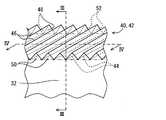
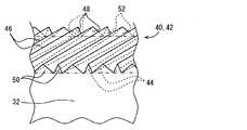
ここで、図3〜7を用いて、コンバイナ30の上端部40の形状について詳細に説明する。図3に示すように、上端部40の全域には、複数の溝44と複数の反射突起46とからなるストライプ構造42が設けられている。より詳細には、前面32と後面34とを貫く複数の溝44がストライプ状に形成され、当該溝44の間には、上方に向かって突出する複数の反射突起46が形成されている。本実施形態においては、溝44と溝44とは実質平行に配置され、また溝44と溝44との間隔は、全て実質一定値に設計されている。そして、1つの反射突起46は、水平面に対して傾斜を設けて平面状に一対形成される反射面48を有している。また、1つの反射突起46は、前面32の一部を構成して前面32の他の部分と境目なく一体的に形成される平面状の突起前面50と、後面34の一部を構成して後面34の他の部分と境目なく一体的に形成される平面状の突起後面52とを有している。 Here, the shape of the
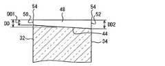
図4では、溝44に沿った方向の断面を図示することにより、溝44の深さDDが示されている。溝44の深さDDは、突起前面50側において最小であり、突起後面52側において最大となって、その間では突起前面50から突起後面52に向かって漸次増大している。具体的には、最大である突起後面52側の溝44の深さDD2が50μm以下に設計されている。なお、本実施形態においては溝44が水平面に対して斜めに形成されているが、溝44が水平面と平行に形成されていてもよい。 In FIG. 4, the depth DD of the
図5では、溝44に垂直な方向の断面を図示することにより、反射突起46の断面形状が示されている。反射突起46は、三角形断面を有しており、より詳細には、二等辺三角形の断面を有している。また、反射突起46の断面において、二等辺をなす一対の反射面48に挟まれて上方に向かって尖る頂角56を有している。そして、図3に示すように、反射突起46は、三角形断面をもって前面32と後面34との間を延伸している。 In FIG. 5, the cross-sectional shape of the
図6に示すように、本実施形態における突起前面50及び突起後面52は、二等辺三角形に形成されている。細部を見ると、突起前面50と突起後面52とは異なる形状に設計されている。突起前面50において、二等辺三角形の頂点54における頂角56の角度VA1は、突起後面52の二等辺三角形の頂点54における頂角56の角度VA2よりも小さく設計されており、例えば、頂角56の角度VA1が100度、頂角56の角度VA2が80度に設計されている。そして、その間の断面において、突起前面50から突起後面52に向かって溝44の深さDDが漸次増大することに伴って、反射突起46の頂角56の角度VAは漸次減少する。例えば、突起前面50の頂点54と突起後面52の頂点54との中点においては、頂角56の角度VAが頂角VA1と頂角VA2との中間値である90度をなすように設計されている。 As shown in FIG. 6, the
なお、コンバイナ30を型成形により製造する場合、上端部40について前後方向にスライドする抜き型を用いることが考えられる。しかし、突起前面50と突起後面52との間の断面において、突起前面50から突起後面52に向かって溝44の深さDDが漸次増大することに伴って、反射突起46の頂角56の角度VAは漸次減少するストライプ構造42により、抜き型は、無理抜きせずとも前後方向にスライド可能となる。 When the
このような3次元的に反射突起46の頂角56が変化する反射面48を有する上端部40に入射する外光の制御について以下に詳細に説明する。図7に示すように、外光は、例えば太陽光であり、ウインドシールド4を介して、コンバイナ30の上端部40に入射する。外光は、仮に上端部40が平面状に形成される場合であれば、そのまま上に向かって反射され、さらにウインドシールド4に反射されることにより、乗員のアイポイント7に到達する。そして、コンバイナ30の上端部40が虚像として車両2の室内から視認されてしまう。ところが、本実施形態の場合では、前述した上端部40の形状により、入射した外光は、車両2において側方に反射される。 The control of external light incident on the
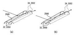
図8では、側方に反射される外光の具体例を示す。図8(a)に1回反射の例として示される外光は、ウインドシールド4を介して、上端部40に入射する。具体的には、外光は、前方上方から、斜めに反射突起46の反射面48に入射する。反射突起46の反射面48は上述した頂角56により水平面に対して傾斜を有するので、反射の法則に従って、例えば後方かつ側方へと反射される。そして、反射光は、反射突起46の間をすり抜けて、そのままコンバイナ30に対して後方かつ側方へと進むのである。 FIG. 8 shows a specific example of external light reflected to the side. External light shown as an example of one-time reflection in FIG. 8A enters the
しかし、外光が、反射面48の比較的前側に入射した場合や溝44の近くに入射した場合などでは、上端部40に2回反射されることがある。図8(b)に2回反射の例として示される外光は、反射突起46の反射面48の比較的前側に入射する。そして、1回反射の場合と同様に、水平面に対して傾斜を有する反射面48により、例えば後方かつ側方へと反射される。ところが、この場合では、外光は、反射突起46の間をすり抜けることができず、隣接する反射面48の比較的後側にてもう1回反射される。2回目の反射箇所では、前述した頂角56の変化により、最初の反射箇所よりも水平面に対してきつい傾斜を有しているので、外光は、最初の反射後の進行方向から変化して、後方上方かつ側方へと反射されることとなるのである。 However, when external light is incident on the relatively front side of the reflecting
側方に反射される外光は、さらにウインドシールド4に反射される場合であっても、さらに側方へと進むので、乗員のアイポイント7に到達し難い。したがって、コンバイナ30の上端部40が虚像として車両2の室内から視認されることが抑制される。 Even if the outside light reflected to the side is further reflected by the windshield 4, the outside light travels further to the side, so that it is difficult to reach the occupant's eye point 7. Therefore, it is suppressed that the
次に、溝44の深さDDと上端部40の虚像の輝度との関係について説明する。図9に示すグラフは、溝44の深さDDの異なる上端部40を有するコンバイナを複数用意して、上端部40の虚像の輝度への影響を調査した結果である。この調査では、車両2の外から擬似太陽光としての外光を想定した実験用光源(照度約100,000lx)により、上端部40に光を照射し、アイポイント7に相当する箇所に輝度計を設置して、ウインドシールド4方向からアイポイント7に相当する箇所に到達する光の輝度(以下、反射輝度)が測定された。この調査によれば、溝44の深さDDが最大150μmの場合では反射輝度が約400cd/m2であり、溝44の深さDDが最大100μmの場合では反射輝度が約300cd/m2であり、溝44の深さDDが最大50μmの場合では反射輝度が約150cd/m2であった。すなわち、溝44の深さDDが小さければ、反射輝度も小さくなる傾向があり、溝44の深さDDが最大50μm以下であれば、乗員が気にならない条件として設定された150cd/m2以下という目標規格が達成されるのである。Next, the relationship between the depth DD of the
加えて、溝44の深さDDと上端部の外観との関係について説明する。本実施形態の溝44の深さDDは最大50μmであるが、溝44の深さDDが100μm以下であれば、コンバイナ30の上端部40を直接目視した場合の外観上、反射突起46が視認され難い。具体的には、表面がすりガラスのような平面状に視認される。また、斜めから上端部40を直接目視したとき、溝44の深さDDが大きい場合では、反射面48が眩しく光って視認されることがあるが、本実施形態の溝44の深さDDの設計では、反射面48の表面積が小さくなるので、このような現象が軽減されるのである。 In addition, the relationship between the depth DD of the
(作用効果)
以上説明した第1実施形態の作用効果を以下に説明する。(Function and effect)
The operational effects of the first embodiment described above will be described below.
第1実施形態によると、車両2において前方を向く前面32と後方を向く後面34との間を貫くように、ストライプ状の複数溝44が上端部40に形成されるコンバイナ30では、それら溝44間にそれぞれ形成される反射突起46が三角形断面をもって前面32及び後面34間を延伸する形態となる。故に各反射突起46では、水平面に対して傾斜する一対の平面状反射面48によって、コンバイナ上端部40への入射外光が側方へと反射されることになる。これによりウインドシールド4においては、各反射突起40による反射外光の到達する領域を、当該到達によりコンバイナ上端部40が虚像として視認される領域から、外すことができる。 According to the first embodiment, in the
ここで特に各反射突起46の反射面48は、三角形断面にて上方に尖る頂角を挟んだ一対の平面状に形成されるので、外光に対する側方への反射機能を任意箇所で発揮して、コンバイナ上端部40の虚像としての視認を抑制できる。さらに、各反射突起において前面32及び後面34の一方から他方へ向かって角度が漸次増加する頂角を挟んだ反射面48のうち、溝44両側の反射面48同士によれば、前方上方からの入射外光に対する最初の反射箇所と後続の反射箇所とで、反射面48の傾斜角度が相異なってくる。こうした傾斜角度の相異によれば、外光に対する側方への反射機能を高めて、コンバイナ上端部40の虚像としての視認抑制効果を確実に発揮できるのである。 Here, in particular, the reflecting
また、第1実施形態によると、溝44の深さの最大値が50μm以下であることにより、当該溝44両側の反射面48による反射輝度が小さくなるので、コンバイナ上端部の虚像としての視認抑制効果を高めることができる。また、溝44の深さDDの最大値が50μm以下であることにより、乗員がコンバイナ上端部40を直接目視した場合に、ストライプ構造42が実像として視認されることも抑制できる。 In addition, according to the first embodiment, since the maximum value of the depth of the
また、第1実施形態によると、ストライプ構造42が全域に設けられるコンバイナ上端部40では、その任意の箇所において外光に対する側方への反射機能を発揮し得る。これにより、コンバイナ上端部40の全域に関して、虚像として視認されることを抑制できる。 Further, according to the first embodiment, the combiner
(第2実施形態)
本発明の第2実施形態は第1実施形態の変形例である。第2実施形態について、第1実施形態とは異なる点を中心に説明する。(Second Embodiment)
The second embodiment of the present invention is a modification of the first embodiment. The second embodiment will be described with a focus on differences from the first embodiment.
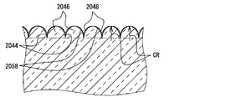
図10〜13を用いて、コンバイナ30の上端部40の形状について詳細に説明する。上端部40の全域には、図10に示すように、複数の溝2044と複数の反射突起2046とからなるストライプ構造2042が設けられている。本実施形態の1つの反射突起2046は、水平面に対して傾斜を設けて曲面状に形成される1つの反射面2048を有している。反射突起2046は、前面32の一部を構成して前面32の他の部分と境目なく一体的に形成される平面状の突起前面2050と、後面34の一部を構成して後面34の他の部分と境目なく一体的に形成される平面状の突起後面2052とを有している。 The shape of the
図11に示すように、溝44の深さDDは第1実施形態と同様に、突起前面2050側において最小であり、突起後面2052側で最大となって、その間では突起前面2050から突起後面2052に向かって漸次増大している。本実施形態においては、例えば、最大である突起後面2052側の溝2044の深さDD2が50μmに設計されており、最小である突起前面2050側の溝2044の深さDD1は20〜30μmの範囲に設計される。 As shown in FIG. 11, the depth DD of the
図12に示すように、本実施形態の反射突起2046は、弧部分2058が上方に湾曲する半月形断面を有している。 As shown in FIG. 12, the
図13に示すように、本実施形態における突起前面2050及び突起後面2052は、弧部分2058が湾曲する半月形状に形成されている。そして、第1実施形態と同様に、細部を見ると、突起前面2050と突起後面2052とは異なる形状に設計されている。突起前面2050における弧部分2058の頂点2054での曲率半径CR1は、突起後面2052における弧部分2058の頂点2054での曲率半径CR2よりも大きく設計されている。例えば、曲率半径CR2は、対応する溝2044の深さDD以下である50μm以下に設計され、曲率半径CR1は50μmよりも大きく設計される。そして、その間の断面において、突起前面2050から突起後面2052に向かって溝2044の深さDDが漸次増大することに伴って、反射突起2046の頂点2054での曲率半径CRは漸次減少する。また、本実施形態における弧部分2058は、円弧ではなく、各頂点2054における曲率半径CR1、CR2対して溝に近づくほど曲率半径CR1a、CR2aが漸次大きくなる曲線状となっている。 As shown in FIG. 13, the
このような3次元的に曲率半径が変化する反射面2048を有する上端部40に入射する外光の制御について以下に詳細に説明する。図12では、側方に反射される外光の具体例を示す。図14(a)に1回反射の例として示される外光は、ウインドシールドを介して、上端部40に入射する。具体的には、外光は、前方上方から、斜めに反射突起2046の反射面2048に入射する。反射突起2046の反射面2048は上述した弧部分2058により水平面に対して傾斜を有するので、反射の法則に従って、例えば後方上方かつ側方へと反射される。 The control of external light incident on the
しかし、外光が、反射面2048の比較的前側に入射した場合や溝2044の近くに入射した場合などでは、上端部40に2回反射されることがある。図14(b)に2回反射の例として示される外光は、例えば反射突起2046の反射面2048の溝2044近くに入射する。そして、水平面に対して傾斜を有する反射面2048により、例えば側方へと反射される。そして、溝2044を挟んだ両側の反射面2048のもう一方により、もう1回反射される。2回目の反射箇所では、前述した曲率半径CRの変化により、最初の反射箇所よりも水平面に対してきつい傾斜を有しているので、外光は、最初の反射後の進行方向から変化して、後方上方かつ側方へと反射されることとなるのである。 However, when external light is incident on the relatively front side of the reflecting
(作用効果)
以上説明した第2実施形態の作用効果を以下に説明する。(Function and effect)
The operational effects of the second embodiment described above will be described below.
第2実施形態によると、車両2において前方を向く前面32と後方を向く後面34との間を貫くように、ストライプ状の複数溝2044が上端部40に形成されるコンバイナ30では、それら溝2044間にそれぞれ形成される反射突起2046が半月形断面をもって前面32及び後面34間を延伸する形態となる。故に各反射突起2046では、半月形断面における弧部分2058の上方への湾曲により水平面に対して傾斜する曲面状の反射面2048によって、コンバイナ上端部40への入射外光が側方へと反射されることになる。これによりウインドシールド4においては、各反射突起2046による反射外光の到達する領域を、当該到達によりコンバイナ上端部40が虚像として視認される領域から、外すことができる。 According to the second embodiment, in the
ここで特に、各反射突起2046において前面32及び後面34の一方から他方へ向かって曲率半径CRが漸次増加する反射面2048のうち、溝2044両側の反射面2048同士によれば、前方上方からの入射外光に対する最初の反射箇所と後続の反射箇所とで、反射面2048の傾斜角度が相異なってくる。こうした傾斜角度の相異によれば、外光に対する側方への反射機能を高めて、コンバイナ上端部40の虚像としての視認抑制効果を確実に発揮できるのである。 Here, in particular, among the
また、第2実施形態の各反射突起2046の反射面2048によると、頂点2054から溝に近づくほど曲率半径が漸次大きくなる曲線状の弧部分2058は、曲率半径が一定の円弧形曲線状である場合よりも、同じ溝2044深さDDにて頂点の曲率半径を小さく設計できる。これによれば、水平面に対する傾斜が各反射突起2046の反射面2048における頂点2054付近まで与えられることになるので、外光に対する側方への反射機能の発揮可能箇所を可及的に拡大して、コンバイナ上端部40の虚像としての視認を抑制できる。 Further, according to the reflecting
また、第2実施形態によると、溝2044の深さDDの最大値が50μm以下であることにより、当該溝2044両側の反射面2048による反射輝度が小さくなるので、コンバイナ上端部40の虚像としての視認抑制効果を高めることができる。また、溝2044の深さDDの最大値が50μm以下であることにより、乗員がコンバイナ上端部40を直接目視した場合に、ストライプ構造2042が実像として視認されることも抑制できる。 Further, according to the second embodiment, since the maximum value of the depth DD of the
また、第2実施形態によると、ストライプ構造2042が全域に設けられるコンバイナ上端部40では、その任意の箇所において外光に対する側方への反射機能を発揮し得る。これにより、コンバイナ上端部40の全域に関して、虚像として視認されることを抑制できる。 Further, according to the second embodiment, the combiner
(他の実施形態)
以上、本発明の複数の実施形態について説明したが、本発明は、それらの実施形態に限定して解釈されるものではなく、本発明の要旨を逸脱しない範囲内において種々の実施形態及び組み合わせに適用することができる。(Other embodiments)
Although a plurality of embodiments of the present invention have been described above, the present invention is not construed as being limited to these embodiments, and various embodiments and combinations can be made without departing from the scope of the present invention. Can be applied.
具体的に、変形例1では、図15に示すように、溝44がストライプ状に形成され、当該溝44の間に上方に向かって突出する反射突起46が形成されている。この例では、溝44と溝44とは実質平行ではなく、前面32又は後面34に対して交互に異なる角度に配置されている。そして、突起前面50から突起後面52に向かって漸次増大する頂角56の角度VAを有する反射突起46と、突起後面52から突起前面50に向かって頂角56の角度VAが漸次増大する反射突起46とが混在し、交互に配置されている。かかる構成であっても、第1実施形態に準じた作用効果の発揮が可能となる。 Specifically, in the first modification, as shown in FIG. 15, the
変形例2では、溝44、2044の深さDDは、突起前面50、2050側において最大であり、突起後面52、2052側において最小となって、その間では突起前面50、2050から突起後面52、2052に向かって漸次減少していてもよい。この例では、例えば、反射突起2046の断面において、突起前面50から突起後面52に向かって溝44の深さDDが漸次減少することに伴って、反射突起46の頂角56の角度VAは漸次増大する。 In the modified example 2, the depth DD of the
変形例3では、ストライプ構造42、2042は、上端部40だけでなく、側端部36又は下端部38の少なくとも一方にも施されていてもよい。 In the third modification, the stripe structures 42 and 2042 may be provided not only on the
変形例4では、3次元的に反射突起46の頂角56が変化する反射面48を有していれば、角度VA1と角度VA2との角度差は1〜2度程度であってもよい。 In the fourth modification, as long as the
変形例5では、弧部分2058は、頂点2054における曲率半径CRに対して溝2044に近づくほど曲率半径が一定又は暫時小さくなっていてもよい。例えば、弧部分2058は、円弧であってもよい。 In the fifth modified example, the radius of curvature of the
変形例6では、溝44、2044の深さDDは、50μm以上であってもよい。 In Modification 6, the depth DD of the
変形例7では、ストライプ構造42、2042は、上端部40の一部に設けられていてもよい。 In the modified example 7, the stripe structures 42 and 2042 may be provided in a part of the
変形例8では、車両2以外の船舶ないしは飛行機等の各種移動体(輸送機器)に、本発明を適用してもよい。 In Modification 8, the present invention may be applied to various moving bodies (transportation equipment) such as ships or airplanes other than the
変形例9では、溝44、2044は、水平面に対して平行に形成されていてもよい。 In the modification 9, the
1 ヘッドアップディスプレイ装置(HUD装置)、2 車両、4 ウインドシールド、8 表示画像、30 コンバイナ、32 前面、34 後面、40 上端部、42、2042 ストライプ構造、44、2044 溝、46、2046 反射突起、48、2048 反射面、54、2054 頂点、56 頂角、2058 弧部分、DD 深さ、VA 角度、CR 曲率半径1 Head-up display device (HUD device), 2 vehicle, 4 windshield, 8 display image, 30 combiner, 32 front surface, 34 rear surface, 40 upper end portion, 42, 2042 stripe structure, 44, 2044 groove, 46, 2046 reflective projection , 48, 2048 Reflective surface, 54, 2054 vertex, 56 apex angle, 2058 arc portion, DD depth, VA angle, CR radius of curvature
Claims (5)
Translated fromJapanese前記コンバイナは、
前記車両において前方を向く前面(32)と、
前記車両において後方を向く後面(34)と、
上端部(40)において前記前面及び前記後面の間を貫くようにストライプ状に形成される複数の溝(44)と、
前記上端部において各前記溝の間にそれぞれ形成される複数の反射突起(46)と、を有し、
各前記反射突起は、三角形断面をもって前記前面及び前記後面の間を延伸し、前記三角形断面において上方に尖る頂角(56)を挟むことにより水平面に対して傾斜する平面状の反射面(48)を一対形成し、それら反射面により光を側方に反射し、
且つ各前記反射突起において前記頂角の角度(VA)は、前記前面及び前記後面の一方から他方に向かって漸次増加することを特徴とするヘッドアップディスプレイ装置。In the vehicle (2) having the windshield (4), a head-up display device including a combiner (30) that forms a virtual image of the display image (8) and displays the virtual image so as to be visible from the interior of the vehicle,
The combiner is
A front face (32) facing forward in the vehicle;
A rear surface (34) facing rearward in the vehicle;
A plurality of grooves (44) formed in a stripe shape so as to penetrate between the front surface and the rear surface at the upper end (40);
A plurality of reflective protrusions (46) formed between the grooves at the upper end,
Each of the reflection projections extends between the front surface and the rear surface with a triangular cross section, and is a flat reflective surface (48) that is inclined with respect to a horizontal plane by sandwiching an apex angle (56) that is sharp upward in the triangular cross section. A pair is formed, the light is reflected to the side by these reflecting surfaces,
In each of the reflection protrusions, the apex angle (VA) gradually increases from one of the front surface and the rear surface toward the other.
前記コンバイナは、
前記車両において前方を向く前面(32)と、
前記車両において後方を向く後面(34)と、
上端部(40)において前記前面及び前記後面の間を貫くようにストライプ状に形成される複数の溝(2044)と、
前記上端部において各前記溝の間にそれぞれ形成される複数の反射突起(2046)と、を有し、
各前記反射突起は、半月形断面をもって前記前面及び前記後面の間を延伸し、前記半月形断面における弧部分(2058)が上方に湾曲することにより水平面に対して傾斜する曲面状の反射面(2048)を形成し、当該反射面により光を側方に反射し、
且つ各前記反射突起において前記弧部分の曲率半径(CR)は、前記前面及び前記後面の一方から他方に向かって漸次増加することを特徴とするヘッドアップディスプレイ装置。In the vehicle (2) having the windshield (4), a head-up display device including a combiner (30) that forms a virtual image of the display image (8) and displays the virtual image so as to be visible from the interior of the vehicle,
The combiner is
A front face (32) facing forward in the vehicle;
A rear surface (34) facing rearward in the vehicle;
A plurality of grooves (2044) formed in a stripe shape so as to penetrate between the front surface and the rear surface at the upper end (40);
A plurality of reflective protrusions (2046) formed between the grooves at the upper end,
Each of the reflection protrusions extends between the front surface and the rear surface with a half-moon-shaped cross section, and a curved reflection surface (inclined with respect to a horizontal plane by an arc portion (2058) in the half-moon-shaped cross section being curved upward) 2048), and reflects light laterally by the reflecting surface,
In each of the reflection protrusions, the radius of curvature (CR) of the arc portion gradually increases from one of the front surface and the rear surface toward the other.
Priority Applications (3)
| Application Number | Priority Date | Filing Date | Title |
|---|---|---|---|
| JP2013087752AJP5958410B2 (en) | 2013-04-18 | 2013-04-18 | Head-up display device |
| PCT/JP2014/001456WO2014171060A1 (en) | 2013-04-18 | 2014-03-14 | Head-up display device |
| US14/783,955US9958675B2 (en) | 2013-04-18 | 2014-03-14 | Head-up display apparatus |
Applications Claiming Priority (1)
| Application Number | Priority Date | Filing Date | Title |
|---|---|---|---|
| JP2013087752AJP5958410B2 (en) | 2013-04-18 | 2013-04-18 | Head-up display device |
Publications (2)
| Publication Number | Publication Date |
|---|---|
| JP2014211533A JP2014211533A (en) | 2014-11-13 |
| JP5958410B2true JP5958410B2 (en) | 2016-08-02 |
Family
ID=51731026
Family Applications (1)
| Application Number | Title | Priority Date | Filing Date |
|---|---|---|---|
| JP2013087752AExpired - Fee RelatedJP5958410B2 (en) | 2013-04-18 | 2013-04-18 | Head-up display device |
Country Status (3)
| Country | Link |
|---|---|
| US (1) | US9958675B2 (en) |
| JP (1) | JP5958410B2 (en) |
| WO (1) | WO2014171060A1 (en) |
Families Citing this family (12)
| Publication number | Priority date | Publication date | Assignee | Title |
|---|---|---|---|---|
| JP6292069B2 (en)* | 2014-07-30 | 2018-03-14 | 株式会社デンソー | Head-up display device |
| CN107735717B (en) | 2015-06-26 | 2020-05-22 | 柯尼卡美能达株式会社 | Head-up display device |
| JP5913714B1 (en)* | 2015-10-19 | 2016-04-27 | 矢崎総業株式会社 | Metal-tone decorative part for vehicle display device and vehicle display device |
| KR102363992B1 (en)* | 2015-11-24 | 2022-02-18 | 현대모비스 주식회사 | Head up display device for vehicle |
| WO2017204133A1 (en)* | 2016-05-25 | 2017-11-30 | コニカミノルタ株式会社 | Display member production method, display member, and head-up display device |
| KR102723518B1 (en)* | 2016-09-29 | 2024-10-30 | 엘지이노텍 주식회사 | Head up display apparatus |
| KR102727063B1 (en)* | 2016-10-05 | 2024-11-07 | 엘지이노텍 주식회사 | Head up display apparatus |
| KR102727064B1 (en)* | 2016-10-05 | 2024-11-07 | 엘지이노텍 주식회사 | Head up display apparatus |
| US20210116706A1 (en)* | 2016-12-12 | 2021-04-22 | Konica Minolta, Inc. | Combiner, head-up display device, and method for manufacturing combiner |
| JP6886330B2 (en)* | 2017-04-07 | 2021-06-16 | 矢崎総業株式会社 | Vehicle display device |
| US10598930B2 (en)* | 2017-11-30 | 2020-03-24 | Automotive Research & Testing Center | Multi-eyebox head-up display device and multilayer combiner |
| WO2025023989A1 (en)* | 2023-07-21 | 2025-01-30 | Harman International Industries, Incorporated | Display with a reflector film |
Family Cites Families (12)
| Publication number | Priority date | Publication date | Assignee | Title |
|---|---|---|---|---|
| US4740780A (en)* | 1985-06-24 | 1988-04-26 | Gec Avionics, Inc. | Head-up display for automobile |
| JP2000039581A (en) | 1998-07-22 | 2000-02-08 | Asahi Glass Co Ltd | Information display device |
| JP2000249965A (en)* | 1999-02-26 | 2000-09-14 | Asahi Glass Co Ltd | Information display device |
| US6836369B2 (en)* | 2002-03-08 | 2004-12-28 | Denso Corporation | Head-up display |
| JP4402916B2 (en) | 2003-08-04 | 2010-01-20 | 矢崎総業株式会社 | Virtual image meter and mirror holder used therefor |
| JP4613581B2 (en)* | 2004-10-29 | 2011-01-19 | 株式会社日立製作所 | Image display device, transmissive screen and reflecting mirror used therefor |
| US7777960B2 (en)* | 2007-09-10 | 2010-08-17 | Microvision, Inc. | Wide field of view head-up display system |
| JP4776669B2 (en)* | 2008-09-25 | 2011-09-21 | 株式会社東芝 | Display device and moving body |
| JP5239925B2 (en)* | 2009-02-16 | 2013-07-17 | 日本精機株式会社 | Display board and instrument device using this display board |
| TWI526718B (en)* | 2010-03-26 | 2016-03-21 | 友輝光電股份有限公司 | A method of forming an uneven structure on a substrate and a method of mold-making |
| US8427751B2 (en) | 2011-01-12 | 2013-04-23 | Lite-On It Corporation | Combiner positioning system for head-up display |
| US8520323B2 (en)* | 2011-08-31 | 2013-08-27 | Prysm, Inc. | Reducing micro-defects in Fresnel lenses |
- 2013
- 2013-04-18JPJP2013087752Apatent/JP5958410B2/ennot_activeExpired - Fee Related
- 2014
- 2014-03-14USUS14/783,955patent/US9958675B2/ennot_activeExpired - Fee Related
- 2014-03-14WOPCT/JP2014/001456patent/WO2014171060A1/enactiveApplication Filing
Also Published As
| Publication number | Publication date |
|---|---|
| US20160070099A1 (en) | 2016-03-10 |
| US9958675B2 (en) | 2018-05-01 |
| JP2014211533A (en) | 2014-11-13 |
| WO2014171060A1 (en) | 2014-10-23 |
Similar Documents
| Publication | Publication Date | Title |
|---|---|---|
| JP5958410B2 (en) | Head-up display device | |
| JP6831900B2 (en) | Head-up display system | |
| CN109564349B (en) | Head-up display device and image display device thereof | |
| CN104090369B (en) | Head-up display | |
| US8870430B2 (en) | Display apparatus and lighting window | |
| JP5287828B2 (en) | Head-up display device | |
| EP3751329B1 (en) | Display device, method, head-up display system, transportation means, and storage medium | |
| US20180292068A1 (en) | Illumination Lens, Illumination Unit, and Head-Up Display Device | |
| WO2018109902A1 (en) | Image display device | |
| WO2011074679A1 (en) | Head-up display device | |
| WO2019049509A1 (en) | Head-up display device and image projection unit | |
| JP2013180713A (en) | On-vehicle display device | |
| JP5439294B2 (en) | Display device | |
| JP6172512B2 (en) | Blind spot assist device | |
| JP2015020669A (en) | Auxiliary image display device of blind area | |
| JP6515796B2 (en) | Head-up display device | |
| JP2015082019A (en) | Head-up display device | |
| US20170039998A1 (en) | Display apparatus and method | |
| US20170153452A1 (en) | Reflecting plate for display, optical system for projecting display light and method of producing windshield | |
| KR102253675B1 (en) | Display Device | |
| JP2012212565A (en) | Light guide | |
| CN109471261A (en) | The head up display with diffusing globe for vehicle | |
| JP2008204908A (en) | Backlight device for onboard liquid crystal display | |
| JP2018163259A (en) | Image display device, virtual image display device, moving object | |
| JP6620687B2 (en) | Head-up display device |
Legal Events
| Date | Code | Title | Description |
|---|---|---|---|
| A621 | Written request for application examination | Free format text:JAPANESE INTERMEDIATE CODE: A621 Effective date:20150609 | |
| TRDD | Decision of grant or rejection written | ||
| A01 | Written decision to grant a patent or to grant a registration (utility model) | Free format text:JAPANESE INTERMEDIATE CODE: A01 Effective date:20160524 | |
| A61 | First payment of annual fees (during grant procedure) | Free format text:JAPANESE INTERMEDIATE CODE: A61 Effective date:20160606 | |
| R151 | Written notification of patent or utility model registration | Ref document number:5958410 Country of ref document:JP Free format text:JAPANESE INTERMEDIATE CODE: R151 | |
| R250 | Receipt of annual fees | Free format text:JAPANESE INTERMEDIATE CODE: R250 | |
| R250 | Receipt of annual fees | Free format text:JAPANESE INTERMEDIATE CODE: R250 | |
| R250 | Receipt of annual fees | Free format text:JAPANESE INTERMEDIATE CODE: R250 | |
| R250 | Receipt of annual fees | Free format text:JAPANESE INTERMEDIATE CODE: R250 | |
| LAPS | Cancellation because of no payment of annual fees |