JP5956750B2 - Gas cutting device, gas cutting robot equipped with the same, and gas cutting method - Google Patents
Gas cutting device, gas cutting robot equipped with the same, and gas cutting methodDownload PDFInfo
- Publication number
- JP5956750B2 JP5956750B2JP2011280246AJP2011280246AJP5956750B2JP 5956750 B2JP5956750 B2JP 5956750B2JP 2011280246 AJP2011280246 AJP 2011280246AJP 2011280246 AJP2011280246 AJP 2011280246AJP 5956750 B2JP5956750 B2JP 5956750B2
- Authority
- JP
- Japan
- Prior art keywords
- cutting
- oxygen
- gas
- workpiece
- flow rate
- Prior art date
- Legal status (The legal status is an assumption and is not a legal conclusion. Google has not performed a legal analysis and makes no representation as to the accuracy of the status listed.)
- Active
Links
Images


Landscapes
- Feeding And Controlling Fuel (AREA)
Description
Translated fromJapanese本発明は、燃料ガスと支援酸素による予熱炎によってワークを予熱し、切断酸素によってワークを切断するガス切断装置とそれを備えたガス切断ロボット及びガス切断方法に関する。 The present invention relates to a gas cutting apparatus that preheats a workpiece with a preheating flame using fuel gas and assisting oxygen, and cuts the workpiece with cutting oxygen, a gas cutting robot including the same, and a gas cutting method.
従来、鋼板や鋼管等の被切断物(この明細書及び特許請求の範囲の書類中においては、これらを総称して「ワーク」という)の切断、穴開け等、種々の分野でアセチレンガス、プロパンガス等(以下、これらを総称して「燃料ガス」という)を用いたガス切断が利用されている。このガス切断は、図5に示すように、切断トーチ100の先端から噴出させる燃料ガス101と支援酸素102とによる高温の予熱炎103によってワーク105を発火温度まで加熱して溶融させ、その予熱炎103の中心部から切断酸素104を噴射することによって溶融金属を吹き飛ばしてワーク105を切断する。 Conventionally, acetylene gas and propane have been used in various fields such as cutting and drilling of workpieces such as steel plates and steel pipes (generally referred to as “workpieces” in this specification and claims). Gas cutting using gas or the like (hereinafter collectively referred to as “fuel gas”) is used. In this gas cutting, as shown in FIG. 5, the
一方、このようなガス切断で切断するワークは、切断形態、厚み等が多種多様である。例えば、図6に示すように、板材110の上面に対して角度β(例えば、60°)で管体111を斜めに貫通させて溶接で固定するような場合、板材110に設ける貫通穴112と管体111との溶接位置において、開先角度をほぼ同じにすることで溶接歪の影響を抑えるようにしたい。 On the other hand, workpieces to be cut by such gas cutting have various cutting forms, thicknesses, and the like. For example, as shown in FIG. 6, when the
そのため、図7(a) 〜(e) に示すように、板材110の貫通穴112の上面113と管体111の外面との開先角度がほぼ同じとなるように、貫通穴112をガス切断する時に、板材110の上面に対する切断トーチ100(図5)の切断角度を変化させる必要がある。この例では、図6に示すA位置からE位置において、図7(a) 〜(e) に示すように、A位置では30°、B位置では40°、C位置では58°、D位置では78°、E位置では90°、と変化する。 Therefore, as shown in FIGS. 7A to 7E, the
そうすると、図8に示すように、板材110の上面113に対して切断トーチ100のトーチ角度をθ1〜θ4へと傾けると、板材110の実切断長さLが変化する。この例では、図示する最短が実切断長さL1、最長が実切断長さL4となる。そのため、その実切断長さLの変化に応じて予熱炎103の強さを調整する必要が生じる。しかも、気温差や湿度等の状況変化によっても予熱炎103の強さを調整する必要が生じる。 Then, as shown in FIG. 8, when the torch angle of the
一方、このような予熱炎の調整作業は、燃料ガスの量や支援酸素の量を微妙に変化させることで適した予熱炎にできるため、熟練作業者であれば、経験によって適した状態に調整することができる。しかし、近年、熟練作業者が減少し、最適な状態に予熱炎を調整することが難しくなっている。 On the other hand, since the preheating flame can be adjusted to a suitable preheating flame by slightly changing the amount of fuel gas and the amount of support oxygen, it can be adjusted to a suitable state by experience for experienced workers. can do. However, in recent years, the number of skilled workers has decreased, making it difficult to adjust the preheating flame to an optimum state.
この種の先行技術として、例えば、切断トーチのそれぞれに、予熱酸素および予熱ガスの流量を調節するコントロールバルブを備えた流量調整装置を設置し、切断トーチ毎に条件の異なる被切断材の切断を同時に行うことができるようにしたものがある。この先行技術では、それぞれの切断トーチに設置された流量調整装置の開量を調整して、予熱、切断、種火の3段階に切り換えられるようにもしている(例えば、特許文献1参照)。 As this type of prior art, for example, each cutting torch is provided with a flow control device equipped with a control valve for adjusting the flow rates of preheated oxygen and preheated gas, so that the material to be cut having different conditions for each cutting torch is cut. There is something that can be done at the same time. In this prior art, the opening amount of the flow rate adjusting device installed in each cutting torch is adjusted so that it can be switched to three stages of preheating, cutting, and fire (see, for example, Patent Document 1).
しかしながら、上記特許文献1では、一つの切断トーチに一つのコントロールバルブが設置された構成であるため、予熱炎の強さを切換・調整する際や切断トーチの切換え時に失火する恐れがある。 However, in the above-mentioned
また、一つの切断トーチに一つのコントロールバルブが設置された構成の場合、例えば、切断途中に予熱炎の強さを切換・調整する時に一時的に予熱炎が大きく変化し、切断面に刻み(ノッチ)が生じる場合がある。この場合、切断後に切断面の修正作業が必要となり、作業効率が悪化する。 In addition, in the case of a configuration in which one control valve is installed in one cutting torch, for example, when the strength of the preheating flame is switched and adjusted during cutting, the preheating flame temporarily changes greatly and is cut into the cut surface ( Notch) may occur. In this case, it is necessary to correct the cut surface after cutting, and work efficiency deteriorates.
そこで、本発明は、失火の恐れなく、状況に応じて予熱炎の強さを容易に切換・調整できるガス切断装置とそれを備えたガス切断ロボット、及びガス切断方法を提供することを目的とする。 SUMMARY OF THE INVENTION An object of the present invention is to provide a gas cutting device that can easily switch and adjust the strength of a preheating flame according to the situation without fear of misfire, a gas cutting robot including the same, and a gas cutting method. To do.
上記目的を達成するために、本発明のガス切断装置は、燃料ガスと支援酸素による予熱炎によってワークを予熱し、切断酸素によってワークを切断するガス切断装置であって、燃料ガス、支援酸素及び切断酸素を噴射してワークを切断する切断トーチと、前記切断トーチへ供給する燃料ガス、支援酸素及び切断酸素の各流量を、異なる流量に調整するバルブユニットを複数有する流量調整手段と、切断条件に応じて、前記複数のバルブユニットの内から切断条件に適したバルブユニットの組み合わせを選択し、前記切断トーチへ燃料ガス、支援酸素及び切断酸素を供給するバルブユニットを駆動する制御手段と、を備え、前記流量調整手段は、燃料ガス、支援酸素及び切断酸素の各流量が着火用流量に調整された少なくとも一つの着火用バルブユニットと、異なる切断条件の流量にそれぞれ調整された複数の流量変更用バルブユニットとを有し、前記制御手段は、全ての切断条件において前記着火用バルブユニットを必ず選択するように構成されている。この明細書及び特許請求の範囲の書類中における「切断条件」は、「切断長さ」、「切断トーチ角度」、「被切断材の材質」などによって設定した条件をいう。 In order to achieve the above object, a gas cutting apparatus according to the present invention is a gas cutting apparatus that preheats a workpiece with a preheating flame using fuel gas and supporting oxygen, and cuts the workpiece with cutting oxygen. A cutting torch for injecting cutting oxygen to cut the workpiece, a flow rate adjusting means having a plurality of valve units for adjusting the flow rates of fuel gas, supporting oxygen and cutting oxygen supplied to the cutting torch to different flow rates, and cutting conditions And a control means for driving a valve unit for supplying fuel gas, assisting oxygen and cutting oxygen to the cutting torch, by selecting a combination of valve units suitable for cutting conditions from the plurality of valve units. And the flow rate adjusting means includes at least one ignition valve in which the flow rates of fuel gas, support oxygen, and cutting oxygen are adjusted to the ignition flow rate. A unit and a plurality of flow rate changing valve units each adjusted to a flow rate of different cutting conditions, and the control means is configured to always select the ignition valve unit in all cutting conditions. . The “cutting conditions” in the specification and claims refers to conditions set by “cutting length”, “cutting torch angle”, “material of material to be cut”, and the like.
この構成により、全ての切断条件において、着火用バルブユニットは必ず選択・駆動されるので、切断条件によって流量変更用バルブユニットの組み合わせを変更したとしても、いずれの組み合わせでも常に着火用バルブユニットから着火用流量の燃料ガス、支援酸素及び切断酸素が供給されているので、切断条件に応じて予熱炎の強さを切換・調整する際に、失火することがないように構成することが可能となる。 With this configuration, the ignition valve unit is always selected and driven under all cutting conditions. Therefore, even if the combination of the flow rate changing valve units is changed according to the cutting conditions, any combination always ignites from the ignition valve unit. Since the flow rate of fuel gas, supporting oxygen and cutting oxygen are supplied, it is possible to configure so as not to misfire when switching and adjusting the strength of the preheating flame according to the cutting conditions. .
また、前記複数のバルブユニットは、燃料ガス、支援酸素及び切断酸素用の各開閉弁と、前記開閉弁と直列に下流側に配置された各手動弁とを有していてもよい。 The plurality of valve units may include on-off valves for fuel gas, assisting oxygen, and cutting oxygen, and manual valves arranged on the downstream side in series with the on-off valves.
このように構成すれば、燃料ガス等の流量は各手動弁の開度を予め調整しておくことにより調整が可能となる。しかも、各手動弁の開度を調整することでガス切断施工中においても調整が可能であり、燃料ガス流量等の微調整が可能となる。 If comprised in this way, the flow volume of fuel gas etc. can be adjusted by adjusting the opening degree of each manual valve beforehand. Moreover, by adjusting the opening degree of each manual valve, it is possible to adjust even during gas cutting construction, and fine adjustment of the fuel gas flow rate and the like is possible.
また、前記開閉弁は、それぞれ電磁開閉弁であってもよい。 The on-off valves may be electromagnetic on-off valves.
このように構成すれば、自動機等において、電磁開閉弁を切換えることによって、燃料ガス等の流量を各手動弁で予め調整した流量に切換えることができ、ガス切断の自動化を促進することが可能となる。 If comprised in this way, in an automatic machine etc., the flow rate of fuel gas etc. can be switched to the flow rate previously adjusted with each manual valve by switching an electromagnetic on-off valve, and automation of gas cutting can be promoted. It becomes.
また、前記切断条件は、ワークの切断面に対する切断トーチのトーチ角度又はワークの実切断長さを所定範囲で区切って設定されていてもよい。 The cutting condition may be set by dividing a torch angle of a cutting torch with respect to a cutting surface of the workpiece or an actual cutting length of the workpiece within a predetermined range.
このように構成すれば、ガス切断において燃料ガス等の流量調整が必要となる重量な要因であるワークの実切断長さ、又はトーチ角度によって変わるワークの実切断長さに応じて設定された切断条件から、バルブユニットの組み合わせを容易に選択・駆動して燃料ガス等の流量を調整することが可能となる。 With this configuration, the cutting set according to the actual cutting length of the workpiece, which is a weight factor that requires adjustment of the flow rate of fuel gas or the like in gas cutting, or the actual cutting length of the workpiece that varies depending on the torch angle From the conditions, it becomes possible to easily select and drive a combination of valve units to adjust the flow rate of fuel gas or the like.
一方、本発明のガス切断ロボットは、前記いずれかのガス切断装置を備え、前記切断トーチをロボットのハンドに保持し、前記制御手段は、前記ワークの切断部分に沿って切断トーチを移動させながら、切断トーチのトーチ角度又はワークの実切断長さの変化に応じた切断条件の流量変更用バルブユニットに自動的に切換えて切断するように構成されている。 On the other hand, a gas cutting robot according to the present invention includes any one of the gas cutting devices described above, holds the cutting torch in a robot hand, and the control unit moves the cutting torch along the cutting portion of the workpiece. The valve unit is configured to automatically switch to a flow rate changing valve unit having a cutting condition corresponding to a change in the torch angle of the cutting torch or the actual cutting length of the workpiece.
この構成により、切断長さが変化するワークの切断部分に沿って切断トーチを移動させ、その切断トーチのトーチ角度又ワークの実切断長さの変化情報に応じて流量変更用バルブユニットを自動的に切換えながらガス切断を行うことができる。 With this configuration, the cutting torch is moved along the cutting portion of the workpiece whose cutting length changes, and the valve unit for changing the flow rate is automatically set according to the change information of the torch angle of the cutting torch or the actual cutting length of the workpiece. Gas cutting can be performed while switching to
一方、本発明のガス切断方法は、燃料ガスと支援酸素による予熱炎によってワークを予熱し、切断酸素によってワークを切断するガス切断方法であって、切断トーチに供給する燃料ガス、支援酸素及び切断酸素の各流量を調整する複数のバルブユニットを、少なくとも一つの着火用流量に調整された着火用バルブユニットと、異なる切断条件の流量にそれぞれ調整された複数の流量変更用バルブユニットとに設定し、前記着火用バルブユニットによる燃料ガス、支援酸素及び切断酸素の切断トーチへの供給を保ちながら、前記ワークの切断条件に適した組み合わせとなるように前記流量変更用バルブユニットを切換えてガス切断を行う。 On the other hand, the gas cutting method of the present invention is a gas cutting method in which a workpiece is preheated by a preheating flame using fuel gas and supporting oxygen, and the workpiece is cut by cutting oxygen, the fuel gas supplied to the cutting torch, supporting oxygen and cutting A plurality of valve units for adjusting each flow rate of oxygen are set as an ignition valve unit adjusted to at least one ignition flow rate and a plurality of flow rate changing valve units adjusted to different cutting conditions. , While maintaining the supply of fuel gas, assisting oxygen and cutting oxygen to the cutting torch by the ignition valve unit, switching the flow rate changing valve unit so as to achieve a combination suitable for the cutting conditions of the workpiece, gas cutting Do.
この構成により、着火用流量に設定された少なくとも一つの着火用バルブユニットから燃料ガス等を常に供給しながら、予め異なる切断条件の流量にそれぞれ調整した複数の流量変更用バルブユニットを切換えながらガス切断を行うので、流量変更用バルブユニットを切換えるときには常に着火用バルブユニットから供給される燃料ガス等で予熱炎を保ちながら各切断条件に応じた強さの予熱炎に切換えることが可能となる。つまり、流量変更用バルブユニットの切換え時に失火することなく切換えることができる。 With this configuration, while always supplying fuel gas, etc. from at least one ignition valve unit set to the ignition flow rate, gas cutting is performed while switching a plurality of flow rate changing valve units adjusted to different flow rates in advance. Therefore, when the flow rate changing valve unit is switched, it is possible to switch to the preheating flame having the strength corresponding to each cutting condition while maintaining the preheating flame with the fuel gas supplied from the ignition valve unit. That is, the switching can be performed without misfiring when the flow rate changing valve unit is switched.
また、前記切断トーチをワークの切断部分に沿ってロボットで移動させながら、前記切断トーチのトーチ角度又はワークの実切断長さの変化に応じた切断条件の流量変更用バルブユニットに自動的に切換えて切断するようにしてもよい。 In addition, while the cutting torch is moved by the robot along the cutting part of the workpiece, the flow is automatically switched to a valve unit for changing the flow rate according to the change of the torch angle of the cutting torch or the actual cutting length of the workpiece. You may make it cut.
このように構成すれば、切断長さが変化するワークの切断部分を、ロボットで流量変更しながら自動的にガス切断を行うことができる。 If comprised in this way, the cutting | disconnection part of the workpiece | work from which cutting length changes can be automatically cut by gas, changing a flow volume with a robot.
本発明によれば、切断条件に応じたバルブユニットの組み合わせを選択・駆動するときに、常に着火用のバルブユニットによって所定の強さの予熱炎が保たれるので、切断条件の変更時も常に予熱炎を安定して保つことが可能となる。 According to the present invention, when a combination of valve units corresponding to the cutting conditions is selected and driven, the preheating flame of a predetermined strength is always maintained by the valve unit for ignition, so even when the cutting conditions are changed, It is possible to keep the preheating flame stable.
以下、本発明の実施形態を図面に基づいて説明する。以下の実施形態では、ガス切断装置の主要構成を模式的に示して説明する。 Hereinafter, embodiments of the present invention will be described with reference to the drawings. In the following embodiments, the main configuration of the gas cutting apparatus will be schematically shown and described.
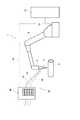
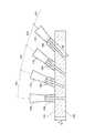
図1に示すように、ガス切断装置10を備えたガス切断設備1としては、多関節のガス切断ロボット2による自動ガス切断が可能なように構成されている。ガス切断ロボット2のハンド3の先端に切断トーチ11が設けられ、この切断トーチ11によってワーク(管体)5に穴を開ける状態を示している。このガス切断ロボット2は、制御装置12と配線13で接続され、制御装置12からの信号で制御されている。 As shown in FIG. 1, a
そして、上記切断トーチ11には、燃料ガス用配管15、支援酸素用配管16、及び切断酸素用配管17が、流量調整手段20を介して接続されている。この実施形態では、上記燃料ガス用配管15を二点鎖線、支援酸素用配管16を一点鎖線、切断酸素用配管17を実線で示している。また、この実施形態では、盤状の流量調整手段20を示している。この流量調整手段20には、後述するように複数のバルブユニット21〜25が設けられている。流量調整手段20は、上記制御装置12と配線14で接続されており、制御装置12からの信号でバルブユニット21〜25が制御されるようになっている。 A
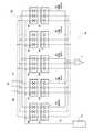
図2に示すように、上記流量調整手段20には、「条件0」と、「切断条件1」から「切断条件4」までの、5つの条件に調整されたバルブユニット21〜25が設けられている。この実施形態では、各バルブユニット21〜25に電磁開閉弁26〜30と手動弁31〜35とが設けられている。電磁開閉弁26〜30は、制御装置12からの信号が配線14を介して入力され、「開放」又は「閉鎖」のいずれかに切換えられる。手動弁31〜35は、電磁開閉弁26〜30の下流側に設けられており、開放した電磁開閉弁26〜30から切断トーチ11に供給される燃料ガス、支援酸素及び切断酸素の各流量を個々に調整できるようになっている。従って、これらの手動弁31〜35で調整された流量の燃料ガス、支援酸素及び切断酸素が切断トーチ11に供給される。 As shown in FIG. 2, the flow rate adjusting means 20 is provided with “unit 0” and valve units 21 to 25 adjusted to five conditions from “cutting
そして、この実施形態では、図示する左端に設けられた「条件0」のバルブユニット21が、燃料ガス、支援酸素及び切断酸素の各流量が着火用流量に設定された着火用バルブユニット21となっている。 In this embodiment, the “condition 0” valve unit 21 provided at the left end in the figure is the ignition valve unit 21 in which the flow rates of the fuel gas, assisting oxygen, and cutting oxygen are set to the ignition flow rates. ing.
また、その横に設けられたバルブユニット22〜25が、燃料ガス、支援酸素及び切断酸素の各流量が異なる流量に調整された「切断条件1」から「切断条件4」の各流量変更用バルブユニット22〜25となっている。この実施形態では、「切断条件1」から「切断条件4」へと徐々に予熱炎(図8)が強くなるように流量が調整されている。 In addition, the
このように構成された流量調整手段20を備えたガス切断装置10によれば、切断作業中は上記「条件0」の着火用バルブユニット21は常に開放して、着火用流量の燃料ガス、支援酸素及び切断酸素が切断トーチ11に供給されるとともに、この着火用バルブユニット21から供給される燃料ガス、支援酸素及び切断酸素に加え、上記「切断条件1」〜「切断条件4」のいずれかにおいて調整された燃料ガス、支援酸素及び切断酸素が切断トーチ11に供給される。例えば、「条件0の流量+切断条件1の流量」、「条件0の流量+切断条件2の流量」、「条件0の流量+切断条件3の流量」、「条件0の流量+切断条件4の流量」のいずれかが切断トーチ11に供給される。 According to the
従って、このように条件0の着火用流量を保ちながら他の切断条件1〜4の流量を加えて所定の予熱炎とすることで、切断条件1〜4の切換え時にも着火用流量の燃料ガス、支援酸素及び切断酸素によって予熱炎を失火させることなく、必要流量の予熱炎への切換えをスムーズに行うことができる。 Therefore, the fuel gas having the ignition flow rate can be changed even when the cutting
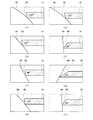
次に、図3(a),(b) を例に、上記ガス切断装置10による切断例を説明する。図3(a) に示すように、例えば、大径管体50に対して角度α(例えば、60°)で小径管体51を斜めに接続する場合、小径管体51の端面は、図3(b) に示すような曲面が連続するような切断面52とする必要がある。 Next, an example of cutting by the
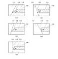
このような例の場合、図4(a) 〜(b) に示すように、大径管体50と溶接する小径管体51の開先角度を同様の角度とするには、ガス切断する切断角度を変化させるように切断トーチ11のトーチ角度θ(図8)を傾けて切断する必要がある。この例では、上記図3(b) に示すA〜Hの8個所における切断角度を示している。例えば、A位置では105°、B位置では101°、C位置では90°、D位置では101°、E位置では105°、F位置では53°、G位置では30°、H位置では53°、と変化させる。そのため、この例における切断長さは、90°が最も短く、30°が最も長くなり、その間においても変化する。 In the case of such an example, as shown in FIGS. 4A to 4B, in order to make the groove angle of the small-
そして、このような例の小径管体51を切断する場合、上記各位置における切断長さにより、例えば、A位置からE位置までは大きく角度が変化しないため、「条件0+切断条件1」の組み合わせで切断する。そして、F位置では「条件0+切断条件3」の組み合わせで切断し、G位置では「条件0+切断条件4」の組み合わせで切断する。そして、H位置では「条件0+切断条件3」の組み合わせに戻して切断する。 And when cutting the small-
このように、ワーク5の切断面に対する切断トーチ11のトーチ角度(例えば、図8に示すθ1〜θ4)を傾けることによって変化する切断角度により、実切断長さLが変化するため、切断トーチ11のトーチ角度θ、又は実切断長さLの変化を所定範囲で区切り、その範囲を「条件0」と「切断条件1〜4」の組み合わせで切断するようにしている。この実施形態では、切断条件が4つであるため、ワーク5の上面に対して直角の角度から例えば70°の範囲までを「切断条件1」、70°〜55°までを「切断条件2」、55°〜45°までを「切断条件3」、45°以下を「切断条件4」として、その角度範囲毎に切断条件を変化させる場合を説明している。 In this way, the actual cutting length L changes depending on the cutting angle that changes by tilting the torch angle (for example, θ1 to θ4 shown in FIG. 8) of the cutting
以上のように、上記ガス切断装置10によれば、着火用流量に設定した着火用バルブユニット21から燃料ガス、支援酸素及び切断酸素を常に供給しながら、異なる切断条件の流量にそれぞれ調整された複数の流量変更用バルブユニット22〜25からの燃料ガス、支援酸素及び切断酸素を加えるようにしているため、予熱炎の切換え時は常に着火用バルブユニット21から供給される燃料ガス、支援酸素及び切断酸素によって予熱炎が保たれるので、失火することなく予熱炎(図8に示す103)を切断に適した燃料ガス、支援酸素及び切断酸素とすることが可能となる。 As described above, according to the
また、この流量変更用バルブユニット22〜25の切換えを電磁開閉弁26〜30で行えるようにすることで、ガス切断する被切断材の切断情報(切断角度、実切断長さ等)を予め制御装置12に記憶させておくことで、自動的に予熱炎(図8に示す103)を変化させてガス切断することもできる。 Further, by switching the flow rate changing
従って、熟練作業者が各切断条件1〜4における燃料ガス、支援酸素及び切断酸素の流量を設定しておけば、熟練ではない作業者や自動機によって熟練作業者と同等のガス切断作業を行うことが可能となる。 Therefore, if the skilled worker sets the flow rates of the fuel gas, assisting oxygen, and cutting oxygen in each cutting
なお、上記実施形態では、切断条件を4条件とした例を示したが、ワーク5の切断条件は作業内容等に応じて決定すればよく、上記実施形態に限定されるものではない。 In the above embodiment, an example in which four cutting conditions are used is shown. However, the cutting condition of the
また、上記実施形態では、条件0の着火用流量に加えて切断条件1〜4のいずれかの流量を加える例を説明したが、条件0の流量を常に切断トーチ11へ供給していれば、切断条件1〜4の複数の流量を加えるような組み合わせでもよく、上記実施形態に限定されるものではない。 Moreover, in the said embodiment, although the example which adds the flow volume in any one of the cutting conditions 1-4 in addition to the flow volume for ignition of the condition 0 was demonstrated, if the flow volume of the condition 0 is always supplied to the
さらに、上述した実施形態は一例を示しており、本発明の要旨を損なわない範囲での種々の変更は可能であり、本発明は上述した実施形態に限定されるものではない。 Furthermore, the above-described embodiment shows an example, and various modifications can be made without departing from the gist of the present invention, and the present invention is not limited to the above-described embodiment.
本発明に係るガス切断装置は、切断部分の実切断長さが変化するような場合に利用できる。 The gas cutting device according to the present invention can be used when the actual cutting length of the cutting portion changes.
1 ガス切断設備
2 ガス切断ロボット
3 ハンド
5 ワーク(管体)
10 ガス切断装置
11 切断トーチ
12 制御装置
13 配線
14 配線
15 燃料ガス用配管
16 支援酸素用配管
17 切断酸素用配管
20 流量調整手段
21 着火用バルブユニット(条件0)
22 流量変更用バルブユニット(切断条件1)
23 流量変更用バルブユニット(切断条件2)
24 流量変更用バルブユニット(切断条件3)
25 流量変更用バルブユニット(切断条件4)
26 電磁開閉弁(条件0)
27 電磁開閉弁(切断条件1)
28 電磁開閉弁(切断条件2)
29 電磁開閉弁(切断条件3)
30 電磁開閉弁(切断条件4)
31 手動弁(条件0)
32 手動弁(切断条件1)
33 手動弁(切断条件2)
34 手動弁(切断条件3)
35 手動弁(切断条件4)
50 大径管体
51 小径管体
52 切断面1 Gas cutting equipment
2 Gas cutting robot
3 hands
5 Workpiece (Tube)
DESCRIPTION OF
22 Flow rate change valve unit (cutting condition 1)
23 Valve unit for changing flow rate (cutting condition 2)
24 Valve unit for changing flow rate (cutting condition 3)
25 Valve unit for changing flow rate (cutting condition 4)
26 Solenoid on-off valve (condition 0)
27 Electromagnetic on-off valve (cutting condition 1)
28 Solenoid open / close valve (cutting condition 2)
29 Electromagnetic on-off valve (cutting condition 3)
30 Electromagnetic on-off valve (cutting condition 4)
31 Manual valve (Condition 0)
32 Manual valve (cutting condition 1)
33 Manual valve (cutting condition 2)
34 Manual valve (cutting condition 3)
35 Manual valve (cutting condition 4)
50
Claims (7)
Translated fromJapanese燃料ガス、支援酸素及び切断酸素を噴射してワークを切断する切断トーチと、
前記切断トーチへ供給する燃料ガス、支援酸素及び切断酸素の各流量を、異なる流量に調整するバルブユニットを複数有する流量調整手段と、
切断条件に応じて、前記複数のバルブユニットの内から切断条件に適したバルブユニットの組み合わせを選択し、前記切断トーチへ燃料ガス、支援酸素及び切断酸素を供給するバルブユニットを駆動する制御手段と、を備え、
前記流量調整手段は、燃料ガス、支援酸素及び切断酸素の各流量が着火用流量に調整された少なくとも一つの着火用バルブユニットと、異なる切断条件の流量にそれぞれ調整された複数の流量変更用バルブユニットとを有し、
前記制御手段は、切断条件の切換え時に、前記着火用バルブユニットを必ず選択し、且つ、前記複数の流量変更用バルブユニットのいずれかを選択するように構成されていることを特徴とするガス切断装置。A gas cutting device that preheats a workpiece with a preheating flame with fuel gas and supporting oxygen, and cuts the workpiece with cutting oxygen,
A cutting torch for cutting a workpiece by injecting fuel gas, supporting oxygen and cutting oxygen;
A flow rate adjusting means having a plurality of valve units for adjusting the flow rates of fuel gas, supporting oxygen and cutting oxygen supplied to the cutting torch to different flow rates;
Control means for driving a valve unit that selects a combination of valve units suitable for the cutting conditions from the plurality of valve units according to the cutting conditions, and supplies fuel gas, assisting oxygen, and cutting oxygen to the cutting torch. With
The flow rate adjusting means includes at least one ignition valve unit in which the flow rates of fuel gas, support oxygen, and cutting oxygen are adjusted to an ignition flow rate, and a plurality of flow rate changing valves that are adjusted to flow rates of different cutting conditions. Unit and
The control means is configured to always select the ignition valve unit andto select any one of the plurality of flow rate changing valve unitswhen switching thecutting condition. apparatus.
前記切断トーチをロボットのハンドに保持し、
前記制御手段は、前記ワークの切断部分に沿って切断トーチを移動させながら、切断トーチのトーチ角度又はワークの実切断長さの変化に応じた切断条件の流量変更用バルブユニットに自動的に切換えて切断するように構成されていることを特徴とするガス切断ロボット。Comprising the gas cutting device according to any one of claims 1 to 4,
Holding the cutting torch on the robot hand,
The control means automatically switches to a valve unit for changing the flow rate of the cutting condition according to the change of the cutting torch angle or the actual cutting length of the workpiece while moving the cutting torch along the cutting portion of the workpiece. A gas cutting robot characterized by being configured to cut by cutting.
切断トーチに供給する燃料ガス、支援酸素及び切断酸素の各流量を調整する複数のバルブユニットを、少なくとも一つの着火用流量に調整された着火用バルブユニットと、異なる切断条件の流量にそれぞれ調整された複数の流量変更用バルブユニットとに設定し、
切断条件の切換え時に、前記着火用バルブユニットによる燃料ガス、支援酸素及び切断酸素の切断トーチへの供給を必ず保ちながら、前記ワークの切断条件に適した組み合わせとなるように前記複数の流量変更用バルブユニットのいずれかを選択するように切換えてガス切断を行うことを特徴とするガス切断方法。A gas cutting method in which a workpiece is preheated by a preheating flame with fuel gas and supporting oxygen, and the workpiece is cut by cutting oxygen,
A plurality of valve units that adjust the flow rates of fuel gas, support oxygen, and cutting oxygen supplied to the cutting torch are adjusted to flow rates that are different from the ignition valve units that are adjusted to at least one ignition flow rate, respectively. Set to multiple flow rate change valve units,
For switching theplurality of flow rates so as to obtain a combination suitable for the cutting conditions of the workpiece whilealways supplying the fuel gas, assisting oxygen and cutting oxygen to the cutting torch by the ignition valve unitwhen switching the cutting conditions A gas cutting method, wherein gas cutting is performedby switchingso as to select any one of the valve units.
Priority Applications (1)
| Application Number | Priority Date | Filing Date | Title |
|---|---|---|---|
| JP2011280246AJP5956750B2 (en) | 2011-12-21 | 2011-12-21 | Gas cutting device, gas cutting robot equipped with the same, and gas cutting method |
Applications Claiming Priority (1)
| Application Number | Priority Date | Filing Date | Title |
|---|---|---|---|
| JP2011280246AJP5956750B2 (en) | 2011-12-21 | 2011-12-21 | Gas cutting device, gas cutting robot equipped with the same, and gas cutting method |
Publications (2)
| Publication Number | Publication Date |
|---|---|
| JP2013128954A JP2013128954A (en) | 2013-07-04 |
| JP5956750B2true JP5956750B2 (en) | 2016-07-27 |
Family
ID=48906985
Family Applications (1)
| Application Number | Title | Priority Date | Filing Date |
|---|---|---|---|
| JP2011280246AActiveJP5956750B2 (en) | 2011-12-21 | 2011-12-21 | Gas cutting device, gas cutting robot equipped with the same, and gas cutting method |
Country Status (1)
| Country | Link |
|---|---|
| JP (1) | JP5956750B2 (en) |
Family Cites Families (7)
| Publication number | Priority date | Publication date | Assignee | Title |
|---|---|---|---|---|
| DE8309304U1 (en)* | 1983-03-29 | 1983-11-03 | GeGa Gesellschaft für Gasetechnik Lotz GmbH & Co KG, 6238 Hofheim | Strand cutting machine for cutting with cutting breaks |
| JPS59191055U (en)* | 1983-06-02 | 1984-12-18 | リンナイ株式会社 | Combustion control device |
| JPH054192A (en)* | 1991-04-05 | 1993-01-14 | Fukushima Seiko Kk | Automatic gas cutting device |
| JPH0683162U (en)* | 1993-04-30 | 1994-11-29 | 株式会社セントラルユニ | Gas cutting machine |
| JPH09225633A (en)* | 1996-02-22 | 1997-09-02 | Tanaka Seisakusho Kk | Gas cutting device |
| JP3382102B2 (en)* | 1996-10-25 | 2003-03-04 | リンナイ株式会社 | Combustion equipment |
| JP2003053548A (en)* | 2001-08-17 | 2003-02-26 | Koike Sanso Kogyo Co Ltd | Flow rate adjusting device and processing device |
- 2011
- 2011-12-21JPJP2011280246Apatent/JP5956750B2/enactiveActive
Also Published As
| Publication number | Publication date |
|---|---|
| JP2013128954A (en) | 2013-07-04 |
Similar Documents
| Publication | Publication Date | Title |
|---|---|---|
| KR102094156B1 (en) | Welding device | |
| US10843285B2 (en) | Welding device | |
| CN103357986B (en) | Welder | |
| US9492882B2 (en) | Plasma cutting method and plasma cutting apparatus | |
| CN103338889B (en) | High toughness weld metals with excellent ductile tear resistance | |
| JP6338290B2 (en) | High strength steel weld metal for demanding structural applications | |
| EP2985088B1 (en) | Method and device for producing rolling roll | |
| JP2009208137A (en) | Plasma mig welding method | |
| US11819958B2 (en) | Build-up welding method | |
| US20110036461A1 (en) | Method and Equipment for Flame Cutting a Steel Part | |
| US20030034334A1 (en) | Flow amount adjustment apparatus and processing apparatus | |
| JP5956750B2 (en) | Gas cutting device, gas cutting robot equipped with the same, and gas cutting method | |
| KR101561692B1 (en) | Plasma cutting device for flange | |
| US8686316B2 (en) | Automatic welding device of the MIG/MAG type | |
| US20080257868A1 (en) | Method and system of welding a bearing | |
| CZ286548B6 (en) | Process of longitudinal welding tubes with flat iron and apparatus for making the same | |
| JP2020138303A (en) | Cutting device and cutting method for non-metal structures | |
| JP2015217414A (en) | Cast piece scarfing device | |
| JPS60238089A (en) | Welding robot device for boiler header | |
| JPH0999366A (en) | Method for welding crossed tube | |
| CN104947104A (en) | Flame remelting device for valve ball core | |
| KR102046230B1 (en) | Apparatus for slanted welding, and method for making pipe using the same | |
| JP2994298B2 (en) | Automatic panel opening forming method | |
| JP5335812B2 (en) | Billet cutting apparatus and billet cutting method | |
| JPH0466613A (en) | Apparatus and method for blowing oxygen |
Legal Events
| Date | Code | Title | Description |
|---|---|---|---|
| A621 | Written request for application examination | Free format text:JAPANESE INTERMEDIATE CODE: A621 Effective date:20141201 | |
| A977 | Report on retrieval | Free format text:JAPANESE INTERMEDIATE CODE: A971007 Effective date:20151222 | |
| A131 | Notification of reasons for refusal | Free format text:JAPANESE INTERMEDIATE CODE: A131 Effective date:20160105 | |
| A521 | Request for written amendment filed | Free format text:JAPANESE INTERMEDIATE CODE: A523 Effective date:20160301 | |
| TRDD | Decision of grant or rejection written | ||
| A01 | Written decision to grant a patent or to grant a registration (utility model) | Free format text:JAPANESE INTERMEDIATE CODE: A01 Effective date:20160524 | |
| A61 | First payment of annual fees (during grant procedure) | Free format text:JAPANESE INTERMEDIATE CODE: A61 Effective date:20160617 | |
| R150 | Certificate of patent or registration of utility model | Ref document number:5956750 Country of ref document:JP Free format text:JAPANESE INTERMEDIATE CODE: R150 | |
| R250 | Receipt of annual fees | Free format text:JAPANESE INTERMEDIATE CODE: R250 | |
| R250 | Receipt of annual fees | Free format text:JAPANESE INTERMEDIATE CODE: R250 | |
| R250 | Receipt of annual fees | Free format text:JAPANESE INTERMEDIATE CODE: R250 |