JP5956523B2 - Detachable structure, portable information device, accessory device and information device set - Google Patents
Detachable structure, portable information device, accessory device and information device setDownload PDFInfo
- Publication number
- JP5956523B2 JP5956523B2JP2014173845AJP2014173845AJP5956523B2JP 5956523 B2JP5956523 B2JP 5956523B2JP 2014173845 AJP2014173845 AJP 2014173845AJP 2014173845 AJP2014173845 AJP 2014173845AJP 5956523 B2JP5956523 B2JP 5956523B2
- Authority
- JP
- Japan
- Prior art keywords
- portable information
- information device
- tablet
- attachment
- magnet
- Prior art date
- Legal status (The legal status is an assumption and is not a legal conclusion. Google has not performed a legal analysis and makes no representation as to the accuracy of the status listed.)
- Active
Links
Images


Landscapes
- Casings For Electric Apparatus (AREA)
Description
Translated fromJapanese本発明は、携帯用情報機器とアクセサリ機器との間の着脱構造、該着脱構造を用いてアクセサリ機器と着脱可能な携帯用情報機器、該着脱構造を用いて携帯用情報機器と着脱可能なアクセサリ機器及び該携帯用情報機器と該アクセサリ機器とを備えた情報機器セットに関する。 The present invention relates to a detachable structure between a portable information device and an accessory device, a portable information device detachable from the accessory device using the detachable structure, and an accessory detachable from the portable information device using the detachable structure. The present invention relates to a device and an information device set including the portable information device and the accessory device.
近年、タッチパネル式の液晶ディスプレイを有し、物理的なキーボードを持たないタブレット型のパーソナルコンピュータ(タブレット型PC)が急速に普及している。タブレット型PCは、持ち運びが容易で入力作業もタッチパネルによって行うことができるため操作が容易である。しかしながら、タブレット型PCは物理的なキーボードを持たないため、例えば、長文の入力作業等に支障を生じる場合がある。また、小型化及び軽量化のためにタブレット型PCに搭載可能なバッテリ容量や機能には限界がある。 In recent years, tablet personal computers (tablet PCs) having a touch panel type liquid crystal display and no physical keyboard are rapidly spreading. The tablet PC is easy to carry because it is easy to carry and input operations can be performed using a touch panel. However, since the tablet PC does not have a physical keyboard, it may hinder long text input operations, for example. In addition, there is a limit to the battery capacity and functions that can be mounted on a tablet PC for miniaturization and weight reduction.
そこで、特許文献1には、拡張用のバッテリやキーボードを搭載したアクセサリ機器にタブレット型PC等の携帯用情報機器を着脱可能とした構成が開示されている。この構成は、板状の筐体構造を有するタブレット型PCの四隅と板状の筐体構造を有するアクセサリ機器の四隅とを磁石の吸着力を利用して着脱する。 Therefore, Patent Document 1 discloses a configuration in which a portable information device such as a tablet PC can be attached to and detached from an accessory device equipped with an expansion battery and a keyboard. In this configuration, the four corners of a tablet PC having a plate-like housing structure and the four corners of an accessory device having a plate-like housing structure are attached and detached using the magnet's attractive force.
上記特許文献1の構成では、タブレット型PCとアクセサリ機器とを互いの四隅同士を磁石で吸着させて着脱するため、装着強度が高いが、筐体四隅の磁石を吸着させ或いは引き離す必要があって着脱操作が面倒である。そこで、この構成では、手動操作によって磁石を移動させることで取り外しを容易にする機構を搭載しているが、構造が複雑化し、タブレット型PCやアクセサリ機器の大型化及び重量化の要因となる。 In the configuration of Patent Document 1 above, since the tablet PC and the accessory device are attached and detached by adsorbing the four corners with magnets, the mounting strength is high, but the magnets at the four corners of the casing need to be adsorbed or separated. The detaching operation is troublesome. Therefore, in this configuration, a mechanism that facilitates the removal by moving the magnet by manual operation is mounted, but the structure becomes complicated, which causes an increase in the size and weight of the tablet PC or accessory device.
一方、磁石による吸着箇所を減らせば取り外しは容易となるが、装着強度を維持することが難しく、装着状態にあるタブレット型PC及びアクセサリ機器を持ち上げたりして傾けた場合に装着状態が外れて機器が落下する懸念がある。 On the other hand, if the number of magnets attracted is reduced, it will be easy to remove, but it will be difficult to maintain the mounting strength, and if the tablet PC and accessory devices in the mounted state are tilted by lifting them up, the mounted state will be removed. There are concerns about falling.
本発明は、上記従来技術の課題を考慮してなされたものであり、携帯用情報機器とアクセサリ機器との間を十分な装着強度を持って容易に着脱可能とする着脱構造、該着脱構造を用いてアクセサリ機器と着脱可能な携帯用情報機器、該着脱構造を用いて携帯用情報機器と着脱可能なアクセサリ機器及び該携帯用情報機器と該アクセサリ機器とを備えた情報機器セットを提供することを目的とする。 The present invention has been made in consideration of the above-described problems of the prior art, and is an attachment / detachment structure that can be easily attached / detached between a portable information device and an accessory device with sufficient attachment strength. Provided is a portable information device that can be attached to and detached from an accessory device, a portable information device that can be attached to and detached from the accessory device using the attachment and detachment structure, and an information device set that includes the portable information device and the accessory device. With the goal.
本発明に係る着脱構造は、板状の筐体構造を有する携帯用情報機器と、板状の筐体構造を有し、前記携帯用情報機器の機能を拡張するアクセサリ機器との着脱構造であって、前記アクセサリ機器は、該アクセサリ機器に前記携帯用情報機器を重ねた状態で前記携帯用情報機器の一側面を磁力によって吸着可能な着脱部を有し、前記携帯用情報機器の一側面及び前記アクセサリ機器の着脱部のいずれか一方には磁石が設けられ、いずれか他方には前記磁石と吸着可能な被吸着体が設けられ、前記磁石又は前記被吸着体の一方は浮動状態で筐体に支持されていることを特徴とする。 An attachment / detachment structure according to the present invention is an attachment / detachment structure between a portable information device having a plate-like housing structure and an accessory device having a plate-like housing structure and extending the function of the portable information device. The accessory device has an attachment / detachment portion that can attract one side surface of the portable information device with magnetic force in a state where the portable information device is stacked on the accessory device, and one side surface of the portable information device and A magnet is provided on one of the attachment / detachment portions of the accessory device, and an adsorbent that can be adsorbed to the magnet is provided on the other, and either the magnet or the adsorbent is in a floating state. It is supported by.
このような構成によれば、携帯用情報機器とアクセサリ機器との間を着脱する磁石又は被吸着体の一方が浮動状態で筐体に支持されている。このため、携帯用情報機器とアクセサリ機器とが互いに重ねられた装着状態から傾けられ、一方の機器と他方の機器との間が離間する方向に移動力を受けた場合であっても、浮動状態にある磁石又は被吸着体が他方の被吸着体又は磁石に対して追従し、その吸着状態が維持される。このため、両機器の装着状態が広い角度範囲に渡って維持され、例えば携帯用情報機器がアクセサリ機器から不用意に落下することを防止できる。しかも、両機器の装着は磁石と被吸着体とを吸着させるだけで十分な装着強度を持って容易に装着することができる一方、両機器の切り離しは磁石と被吸着体との吸着状態を解除するだけでよく、着脱時の操作性が高い。 According to such a configuration, one of the magnet that attaches and detaches between the portable information device and the accessory device or the object to be attracted is supported by the housing in a floating state. For this reason, even when the portable information device and the accessory device are tilted from the mounted state where they are stacked on each other and receive a moving force in a direction in which the one device and the other device are separated from each other, the floating state The magnet or the object to be adsorbed in the position follows the other object to be adsorbed or the magnet, and the adsorption state is maintained. For this reason, the mounting state of both devices is maintained over a wide angle range, and for example, the portable information device can be prevented from inadvertently dropping from the accessory device. Moreover, both devices can be easily mounted with sufficient mounting strength by simply adsorbing the magnet and the object to be adsorbed, while disconnecting both devices cancels the adsorption state between the magnet and the object to be adsorbed. All you need to do is high operability when attaching and detaching.
前記アクセサリ機器の着脱部には、その先端面に前記被吸着体を浮動状態で支持した凸部が設けられ、前記携帯用情報機器の一側面には、前記凸部を挿入可能であると共に、その底面に前記磁石を支持した凹部が設けられているとよい。そうすると、携帯用情報機器とアクセサリ機器との装着時の位置決めが容易となる。また、携帯用情報機器には凹部を設けることにより、単体でも使用される携帯用情報機器の外観上に凸部が突出することを防止できる。 The attachment / detachment portion of the accessory device is provided with a convex portion that supports the adsorbed body in a floating state on a tip surface thereof, and the convex portion can be inserted into one side surface of the portable information device, It is preferable that a concave portion supporting the magnet is provided on the bottom surface. If it does so, positioning at the time of mounting | wearing with portable information equipment and accessory equipment will become easy. Further, by providing the portable information device with the concave portion, it is possible to prevent the convex portion from protruding on the appearance of the portable information device that is used alone.
前記被吸着体は、前記凸部の前記凹部への挿入方向に沿って前記凸部の先端面から進退可能であると、凹部の底部に設けられた磁石へと確実に吸着させることができる。 The adsorbable body can be reliably adsorbed to the magnet provided at the bottom of the concave portion when it can advance and retreat from the tip surface of the convex portion along the insertion direction of the convex portion into the concave portion.
前記被吸着体を前記先端面から後退する方向に常時付勢する弾性部材を備えると、磁石と吸着していない状態での被吸着体のがたつきを防止できる。 When an elastic member that constantly urges the adsorbed body in the direction of retreating from the tip end surface is provided, rattling of the adsorbed object in a state where it is not adsorbed to the magnet can be prevented.
前記携帯用情報機器と前記アクセサリ機器とを重ねて配置し、前記磁石と前記被吸着体との吸着作用により前記携帯用情報機器と前記アクセサリ機器とを装着した状態から、前記着脱部を中心として前記携帯用情報機器を前記アクセサリ機器から離間する方向に回動させた場合に、所定角度まで回動させるまでは前記被吸着体が前記磁石に吸着したまま移動し、前記磁石と前記被吸着体との吸着状態が維持される一方、所定角度を超えると該吸着状態が解除されるとよい。そうすると、携帯用情報機器とアクセサリ機器とを重ねて装着した状態で傾けた場合等に携帯用除法機器が容易に落下することをより確実に防止できると共に、両者の取り外し時には所定角度以上に携帯用情報機器を回動させるだけで容易に装着状態を解除することができる。 From the state where the portable information device and the accessory device are arranged so as to overlap each other and the portable information device and the accessory device are attached by the adsorption action of the magnet and the object to be adsorbed, with the attachment / detachment portion as a center. When the portable information device is rotated in a direction away from the accessory device, the object to be adsorbed moves while being adsorbed to the magnet until it is rotated to a predetermined angle, and the magnet and the object to be adsorbed are moved. While the adsorbed state is maintained, the adsorbed state may be canceled when a predetermined angle is exceeded. Then, when the portable information device and the accessory device are stacked and tilted, the portable removal device can be more reliably prevented from falling off, and when removing both, the portable information device and the accessory device are more portable than a predetermined angle. The mounted state can be easily released simply by rotating the information device.
また、本発明に係る携帯用情報機器は、上記構成からなる着脱構造を用いて前記アクセサリ機器と着脱可能に構成したことを特徴とする。 Moreover, the portable information device according to the present invention is configured to be detachable from the accessory device using the detachable structure having the above-described configuration.
この場合、当該携帯用情報機器は、タッチ操作可能なディスプレイを備えたタブレット型のパーソナルコンピュータであってもよい。 In this case, the portable information device may be a tablet personal computer including a touch-operable display.
また、本発明に係るアクセサリ機器は、上記構成からなる着脱構造を用いて前記携帯用情報機器と着脱可能に構成したことを特徴とする。 Moreover, the accessory apparatus which concerns on this invention was comprised so that it could attach or detach with the said portable information device using the attachment or detachment structure which consists of the said structure.
この場合、当該アクセサリ機器は、前記携帯用情報機器に対する入力操作が可能なキーボードを備えた構成であってもよい。 In this case, the accessory device may include a keyboard capable of performing an input operation on the portable information device.
また、本発明に係る情報機器セットは、上記構成からなる着脱構造を用いて前記携帯用情報機器と前記アクセサリ機器とを着脱可能に構成し、前記携帯用情報機器は、タッチ操作可能なディスプレイを備えたタブレット型のパーソナルコンピュータであり、前記アクセサリ機器は、前記携帯用情報機器に対する入力操作が可能なキーボードを備えたキーボードユニットであることを特徴とする。 In addition, an information device set according to the present invention is configured such that the portable information device and the accessory device are detachable using the detachable structure having the above-described configuration, and the portable information device includes a touch-operable display. The accessory device is a keyboard unit including a keyboard capable of performing an input operation on the portable information device.
本発明によれば、携帯用情報機器とアクセサリ機器とを装着する磁石又は被吸着体の一方が浮動状態で筐体に支持されているため、携帯用情報機器とアクセサリ機器との間を十分な装着強度を持って容易に着脱可能に構成することができる。 According to the present invention, since one of the magnet or the object to be adsorbed for mounting the portable information device and the accessory device is supported by the casing in a floating state, there is a sufficient gap between the portable information device and the accessory device. It can be configured to be easily detachable with mounting strength.
以下、本発明に係る着脱構造について、この構造によって着脱可能な携帯用情報機器及びアクセサリ機器を例示して好適な実施の形態を挙げ、添付の図面を参照しながら詳細に説明する。 Hereinafter, a detachable structure according to the present invention will be described in detail with reference to the accompanying drawings by exemplifying a preferred embodiment by exemplifying portable information devices and accessory devices detachable by this structure.
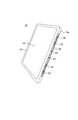
図1は、本発明の一実施形態に係る着脱構造10を用いてタブレット型PC12をキーボードユニット14に装着した状態を示す斜視図であり、図2は、タブレット型PC12の構成例を示す斜視図である。また、図3は、着脱構造10を用いてタブレット型PC12をキーボードユニット14に装着した状態での要部拡大側面図である。図1では、キーボードユニット14の構成を明示するため、タブレット型PC12については2点鎖線によって外形のみを図示している。 FIG. 1 is a perspective view showing a state in which a
本実施形態では、携帯用情報機器としてタブレット型PC12(以下、単に「タブレット12」ともいう)を例示し、このタブレット12をアクセサリ機器の一例としてのキーボードユニット14(以下、単に「ユニット14」ともいう)に対して着脱構造10によって着脱する構成を例示する。携帯用情報機器はスマートフォン等でもよく、アクセサリ機器はキーボードを持たないバッテリユニット等でもよい。 In the present embodiment, a tablet PC 12 (hereinafter also simply referred to as “
図1〜図3に示すように、タブレット12はタッチ操作可能なディスプレイ16を備える。タブレット12は、板状構造を有する筐体18の内部に基板、演算装置、メモリ等の各種電子部品を収納して構成されている。タブレット12は、筐体18の一側面がユニット14に対する着脱面18aとなる。着脱面18aには、長手方向に伸びた溝状の凹部20が形成されている。凹部20の底部には、合計4個の磁石22が並設されると共に、中央の磁石22,22間には一対の位置決め穴24,24が形成されている。 As shown in FIGS. 1 to 3, the
ユニット14は、タブレット12の外部入力手段として機能する物理的なキーボード26及びタッチパッド27を備えた拡張用機器である。ユニット14は、タブレット12をノートブック型パーソナルコンピュータ(ノート型PC)のように機能させ、その利便性を向上させることができる。ユニット14は、キーボード26等以外の電子部品、例えば、バッテリやハードディスクドライブ、光学ディスクドライブ装置等を備えてもよい。 The
ユニット14は、全体として板状の筐体構造を有しており、その後端部には幅方向全体に渡って上方へと突出した長尺ブロック形状の着脱部28が設けられ、着脱部28の前側大部分には一段薄く形成された板状のキーボード26が設けられている。図1及び図3に示すように、着脱部28はその前面(キーボード26側の側面)がタブレット12が着脱される被着脱面28aとなる。被着脱面28aには、長手方向に伸び、タブレット12の凹部20に挿入可能な凸部30が形成されている。 The
図4は、キーボードユニット14の着脱部28周辺を拡大した斜視図であり、図5は、着脱構造10を用いてタブレット型PC12をキーボードユニット14に装着した状態を模式的に示す側面断面図である。 4 is an enlarged perspective view of the vicinity of the attaching / detaching
図1に示すように、凸部30の前面には、その長手方向に並ぶように被吸着部32が4個設けられている。4個の被吸着部32は、凸部30がタブレット12の凹部20に挿入された状態で4個の磁石22に吸着可能な位置に配置されている。各被吸着部32は、図4及び図5に示すように上下に並んだ可動板32a及び固定板32bを備える。 As shown in FIG. 1, four attracted
これら可動板32a及び固定板32bは、タブレット12の磁石22と吸着可能な磁石又はスチール等の金属で構成された被吸着体である。可動板32aは、凸部30の凹部20への挿入方向(前後方向)に沿って進退可能な浮動状態で支持された断面略L字状の金属板である。可動板32aは、凸部30の奥側に配置されたL字の鉛直方向部分と固定板32bとの間に介装された圧縮ばねであるコイルばね(弾性部材)33により、常時凸部30の前面から後退する方向に付勢されている。これにより、磁石22と吸着していない状態での可動板32aのがたつきが防止される。図5に示すようにタブレット12が着脱部28に装着された状態(クローズモード)又は図4に示すようにタブレット12が着脱部28から取り外された状態において、可動板32aの先端面は固定板32bの先端面と面一位置にあり、凸部30の前面の一部を構成する。固定板32bを省略し、被吸着部32を可動板32aのみで構成してもよい。 The
図1に示すように、中央の被吸着部32,32間には一対の位置決め突起34,34が形成されている。位置決め突起34は、タブレット12の位置決め穴24に嵌合されることにより、タブレット12とユニット14との装着位置を規定する位置決め用の部材である。 As shown in FIG. 1, a pair of
ユニット14の上面後方寄りであって、キーボード26と着脱部28とに挟まれた部分には、図3に示す側面視で略三角形状の溝部36が幅方向に渡って形成されている。溝部36は、タブレット12の着脱面18aを嵌合させることにより、ユニット14に対してタブレット12を立脚姿勢に保持してノート型PCとして使用する際に用いられる着脱部である(図3中に2点鎖線で示すタブレット12参照)。溝部36の後壁面にはタブレット12の背面を支持するクッション部材37が複数設けられる。タブレット12の着脱面18aが着地する溝部36の前壁面には、位置決め穴24と嵌合可能な位置決め突起38(図1参照)と、タブレット12の図示しないコネクタと接続される図示しない端子とが設けられている。 Near the rear side of the upper surface of the
このようなタブレット12及びユニット14で構成される電子機器(情報機器セット)では、その収納時や持ち運び時にはタブレット12を裏返し、ディスプレイ16がキーボード26に対面する水平姿勢としてユニット14の上面上に載置し、着脱構造10を用いて着脱面18aを着脱部28の被着脱面28aに装着するクローズモードとする(図1及び図3中に実線で示すタブレット12参照)。これにより、ディスプレイ16及びキーボード26が外部に露出することなくタブレット12とユニット14とを閉じた状態で一体化することができ、情報機器セットの持ち運びが容易となる。また、図3中に実線で示す姿勢からタブレット12を上下反転させた状態とし、着脱構造10を用いて両者を装着するとタブレットモードになる。このタブレットモードでは、ディスプレイ16が上面となるため、ユニット14に装着した状態のままでタブレット12を使用することができる。 In such an electronic device (information device set) composed of the
一方、タブレット12の着脱面18aを溝部36に嵌合装着し、タブレット12をユニット14の後端側で立脚姿勢に固定するとノートモードになる。これにより、キーボード26をタブレット12の入力手段として有効に機能させ、情報機器セットを一般的なノート型PCと同様に使用することができる。 On the other hand, when the attachment /
次に、本実施形態に係る着脱構造10を用いたタブレット型PC12とキーボードユニット14との着脱動作について説明する。 Next, an attaching / detaching operation between the
先ず、着脱構造10を用いてタブレット12をユニット14に装着する場合には、タブレット12をキーボード26の上面上に水平姿勢で重ねて配置し、着脱面18aを着脱部28の被着脱面28aに当接させる。これにより、位置決め突起34と位置決め穴24の位置決め作用下に凸部30と凹部20とが嵌合され、図5に示すように磁石22が被吸着部32の可動板32a及び固定板32bと吸着する。そうすると、タブレット12とユニット14とが重ねられた状態で一体になる。この状態では、磁石22と被吸着部32との位置関係が磁力の方向に沿った方向となるため、タブレット12とユニット14とが強固に固定される。また、この装着時、タブレット12の着脱面18aを被着脱面28aに近づけると、最初に可動板32aが磁石22に引き寄せられてスライドして磁石22と吸着するため、装着時の操作性が高い。 First, when the
次に、このように装着されたタブレット12をユニット14から取り外す場合には、例えばタブレット12の前端部を把持して着脱構造10によってユニット14に固定されている着脱面18a側を回動軸としてタブレット12を回動させるように持ち上げる(図6参照)。ここで、被吸着部32に可動板32aがなく固定板32bのみが設けられている場合は、磁力の方向に直交する方向に外力が加えられるため、タブレット12がユニット14から容易に外れてしまう懸念がある。 Next, when the
ところが、当該着脱構造10では、図6に示すように、浮動状態でユニット14の筐体に支持された可動板32aを有するため、回動方向に持ち上げられるタブレット12の磁石22に吸着した状態のまま、可動板32aがコイルばね33の付勢力に抗して前方にスライド移動する。このため、ユニット14とタブレット12との間が所定の角度位置になるまでは可動板32aと磁石22との吸着状態を維持しておくことができる。 However, since the attachment /
本実施形態の場合、例えば、図6に示すようにタブレット12の筐体18の後端角部がユニット14の着脱部28の被着脱面28aに当接し、タブレット12の凹部20が着脱部28の凸部30から完全に抜け出すまでの間は可動板32aと磁石22との吸着状態が維持されるように設定されている。すなわち、タブレット12の筐体18の前後方向に沿う直線Aと、ユニット14の筐体の前後方向に沿う直線Bとの間の角度θが所定角度、例えば20度になるまで前記吸着状態が維持されるように設定されている。この所定角度までの間は磁石22と可動板32aとの間が確実に固定されているため、タブレット12がユニット14から容易に脱落してしまうことがない。 In the case of the present embodiment, for example, as shown in FIG. 6, the rear end corner of the
一方、図6に示す状態からさらにタブレット12を持ち上げて回動させると、図7に示すように可動板32aが前進限界に達するため、可動板32aと磁石22との吸着状態が一挙に解除される。これにより、タブレット12がユニット14から容易に取り外され、可動板32aはコイルばね33の付勢力によって初期位置に戻る。 On the other hand, when the
ここで、着脱構造10では、上記のように装着状態にあるタブレット12を所定角度(例えば角度θが20度)になるまでは、可動板32aと磁石22との吸着状態が維持される。従って、図5に示すようにタブレット12がユニット14に装着されてクローズモードにある情報機器ユニットを、例えば図6中の直線Aが鉛直方向となる姿勢まで傾けた場合には、タブレット12が下方を向いた着脱部28の被着脱面28aから鉛直下方に垂下され、タブレット12がユニット14との間に角度θを持って振り子状態となる。しかしながら、着脱構造10では、このようにタブレット12が振り子状態でぶら下がった場合であっても、タブレット12とユニット14との間の角度θが所定角度までの間は可動板32aと磁石22との吸着作用が維持されるため、タブレット12がユニット14から落下することがない。このため、例えば鞄に収容した情報機器セットを把持して取り出す場合等に誤って着脱構造10での装着状態が外れ、タブレット12が落下することを防止できる。一方、所定角度以上にタブレット12を回動させると、可動板32aと磁石22との吸着状態が解除されるため、タブレット12をユニット14から容易に取り外すことができる。 Here, in the attachment /
以上のように、本実施形態に係る着脱構造10は、板状の筐体構造を有するタブレット型PC12と、板状の筐体構造を有し、タブレット型PC12の機能を拡張するキーボードユニット14との着脱に用いられる。この着脱構造10において、ユニット14は、該ユニット14にタブレット12を重ねた状態でタブレット12の着脱面18aを磁力によって吸着可能な着脱部28を有し、タブレット12の着脱面18aには磁石22が設けられ、ユニット14の着脱部28には磁石22と吸着可能な被吸着部32が設けられ、被吸着部32を構成する可動板32aは浮動状態でユニット14の筐体に支持されている。 As described above, the
従って、着脱構造10では、ユニット14の着脱部28に浮動状態で支持された可動板32aを備えることにより、ユニット14に装着されたタブレット12が磁石22による吸着部分を中心として回動された場合であっても、タブレット12と共に離間する磁石22に対して可動板32aが追従して吸着状態が維持される。このため、タブレット12とユニット14との間を十分な装着強度を持って容易に装着することができ、装着状態にあるタブレット12及びユニット14を傾けた場合にも両者の吸着状態が広い角度範囲に渡って維持され、タブレット12が不用意に落下することを防止できる。しかも、タブレット12を十分に持ち上げて着脱面18aと着脱部28との間での吸着状態を解除するだけでタブレット12をユニット14から取り外すことができるため、取り外しが容易である。 Therefore, in the attachment /
なお、可動板32aはスライド構造以外であってもよい。例えば、図8及び図9に示すように、被吸着部32を構成する可動板32aを回動構造の可動板42に代えた着脱構造40としてもよい。 The
可動板42は、上端側の回動軸42aによって凸部30の前面付近で回動可能に軸支されている。この可動板42を用いた着脱構造40では、図9に示すようにタブレット12が所定角度まで回動するまでの間は可動板42が回動軸42aを中心に回動するため、可動板42と磁石22との吸着状態が維持される。一方、タブレット12が所定角度よりもさらに回動すると、図9中に2点鎖線で示すように可動板42は上端角部の回動規制部42bが凸部30の筐体に当接してそれ以上の回動が不能となり、磁石22から切り離される。これにより、可動板42と磁石22との吸着状態が解消され、タブレット12がユニット14から取り外され、可動板32aは回動軸42aに外挿されたねじりコイルばね(弾性部材)44の付勢力によって初期位置に戻る。 The
なお、本発明は、上記した実施形態に限定されるものではなく、本発明の主旨を逸脱しない範囲で自由に変更できることは勿論である。 It should be noted that the present invention is not limited to the above-described embodiment, and it is needless to say that the present invention can be freely changed without departing from the gist of the present invention.
上記実施形態に係る着脱構造10(40)では、タブレット型PC12に磁石22を設け、キーボードユニット14に浮動構造の可動板32a(42)を設けた構成を例示したが、タブレット型PC12に金属板又は浮動式の磁石若しくは金属板を設け、キーボードユニット14に浮動式の磁石又は固定式の金属板若しくは磁石を設けてもよい。 In the attachment / detachment structure 10 (40) according to the above embodiment, a configuration in which the
10,40 着脱構造
12 タブレット型PC
14 キーボードユニット
16 ディスプレイ
18 筐体
18a 着脱面
20 凹部
22 磁石
26 キーボード
28 着脱部
28a 被着脱面
30 凸部
32 被吸着部
32a,42 可動板
32b 固定板
33 コイルばね
44 ねじりコイルばね10, 40
DESCRIPTION OF
Claims (8)
Translated fromJapanese前記アクセサリ機器は、該アクセサリ機器に前記携帯用情報機器を重ねた状態で前記携帯用情報機器の一側面を磁力によって吸着可能な着脱部を有し、
前記携帯用情報機器の一側面及び前記アクセサリ機器の着脱部のいずれか一方には磁石が設けられ、いずれか他方には前記磁石と吸着可能な被吸着体が設けられ、
前記磁石又は前記被吸着体の一方は浮動状態で筐体に支持され、
前記アクセサリ機器の着脱部には、その先端面に前記被吸着体を浮動状態で支持した凸部が設けられ、
前記携帯用情報機器の一側面には、前記凸部を挿入可能であると共に、その底面に前記磁石を支持した凹部が設けられ、
前記携帯用情報機器と前記アクセサリ機器とを重ねて配置し、前記磁石と前記被吸着体との吸着作用により前記携帯用情報機器と前記アクセサリ機器とを装着した状態から、前記着脱部を中心として前記携帯用情報機器を前記アクセサリ機器から離間する方向に回動させた場合に、所定角度まで回動させるまでは前記被吸着体が前記磁石に吸着したまま移動し、前記磁石と前記被吸着体との吸着状態が維持される一方、所定角度を超えると該吸着状態が解除されることを特徴とする着脱構造。A detachable structure between a portable information device having a plate-like housing structure and an accessory device having a plate-like housing structure and extending the function of the portable information device,
The accessory device has a detachable portion that can attract one side surface of the portable information device by magnetic force in a state where the portable information device is stacked on the accessory device,
A magnet is provided on one of the one side surface of the portable information device and the attachment / detachment portion of the accessory device, and an adsorbent to be adsorbed to the magnet is provided on the other,
One of the magnet or the object to be adsorbed is supported by the housing in a floating state,
The attachment / detachment portion of the accessory device is provided with a convex portion that supports the adsorbed body in a floating state on a tip surface thereof,
On one side of the portable information device, the convex portion can be inserted, and a concave portion supporting the magnet is provided on the bottom surface thereof.
From the state where the portable information device and the accessory device are arranged so as to overlap each other and the portable information device and the accessory device are attached by the adsorption action of the magnet and the object to be adsorbed, with the attachment / detachment portion as a center. When the portable information device is rotated in a direction away from the accessory device, the object to be adsorbed moves while being adsorbed to the magnet until it is rotated to a predetermined angle, and the magnet and the object to be adsorbed are moved. detachable structureone, exceeds a predetermined angle adsorption state is canceled, characterized in Rukotoadsorption state is maintained with.
前記被吸着体は、前記凸部の前記凹部への挿入方向に沿って前記凸部の先端面から進退可能であることを特徴とする着脱構造。The attachment / detachment structure according to claim1 ,
The attachment / detachment structure is characterized in that the adsorbed body is capable of moving forward and backward from the front end surface of the convex portion along the insertion direction of the convex portion into the concave portion.
前記被吸着体を前記先端面から後退する方向に常時付勢する弾性部材を備えることを特徴とする着脱構造。The attachment / detachment structure according to claim2 ,
An attachment / detachment structure comprising: an elastic member that constantly urges the adsorbed body in a direction of retreating from the tip surface.
タッチ操作可能なディスプレイを備えたタブレット型のパーソナルコンピュータであることを特徴とする携帯用情報機器。The portable information device according to claim4 , wherein
A portable information device, which is a tablet personal computer having a display capable of touch operation.
前記携帯用情報機器に対する入力操作が可能なキーボードを備えたことを特徴とするアクセサリ機器。The accessory device according to claim6 , wherein
An accessory device comprising a keyboard capable of performing an input operation on the portable information device.
前記携帯用情報機器は、タッチ操作可能なディスプレイを備えたタブレット型のパーソナルコンピュータであり、
前記アクセサリ機器は、前記携帯用情報機器に対する入力操作が可能なキーボードを備えたキーボードユニットであることを特徴とする情報機器セット。
The portable information device and the accessory device are configured to be detachable using the detachable structure according to any one of claims 1 to3 .
The portable information device is a tablet personal computer equipped with a touch-operable display,
The information device set according to claim 1, wherein the accessory device is a keyboard unit including a keyboard capable of performing an input operation on the portable information device.
Priority Applications (1)
| Application Number | Priority Date | Filing Date | Title |
|---|---|---|---|
| JP2014173845AJP5956523B2 (en) | 2014-08-28 | 2014-08-28 | Detachable structure, portable information device, accessory device and information device set |
Applications Claiming Priority (1)
| Application Number | Priority Date | Filing Date | Title |
|---|---|---|---|
| JP2014173845AJP5956523B2 (en) | 2014-08-28 | 2014-08-28 | Detachable structure, portable information device, accessory device and information device set |
Publications (2)
| Publication Number | Publication Date |
|---|---|
| JP2016048520A JP2016048520A (en) | 2016-04-07 |
| JP5956523B2true JP5956523B2 (en) | 2016-07-27 |
Family
ID=55649365
Family Applications (1)
| Application Number | Title | Priority Date | Filing Date |
|---|---|---|---|
| JP2014173845AActiveJP5956523B2 (en) | 2014-08-28 | 2014-08-28 | Detachable structure, portable information device, accessory device and information device set |
Country Status (1)
| Country | Link |
|---|---|
| JP (1) | JP5956523B2 (en) |
Families Citing this family (3)
| Publication number | Priority date | Publication date | Assignee | Title |
|---|---|---|---|---|
| US10579097B2 (en) | 2015-09-04 | 2020-03-03 | Apple Inc. | Electronic device with contacts flush with housing |
| KR102373875B1 (en) | 2017-05-22 | 2022-03-14 | 삼성전자주식회사 | Electronic device with multi-angle cradling |
| CN113138624B (en)* | 2020-01-17 | 2024-08-06 | 神讯电脑(昆山)有限公司 | Notebook computer and keyboard decoration board thereof |
Family Cites Families (4)
| Publication number | Priority date | Publication date | Assignee | Title |
|---|---|---|---|---|
| JP5029549B2 (en)* | 2008-09-18 | 2012-09-19 | 富士通株式会社 | Electronics |
| US8264310B2 (en)* | 2010-09-17 | 2012-09-11 | Apple Inc. | Accessory device for peek mode |
| JP2014149663A (en)* | 2013-01-31 | 2014-08-21 | Toshiba Corp | Electronic apparatus |
| US8599542B1 (en)* | 2013-05-17 | 2013-12-03 | Zagg Intellectual Property Holding Co., Inc. | Combined cover, keyboard and stand for tablet computer with reversable connection for keyboard and reading configuration |
- 2014
- 2014-08-28JPJP2014173845Apatent/JP5956523B2/enactiveActive
Also Published As
| Publication number | Publication date |
|---|---|
| JP2016048520A (en) | 2016-04-07 |
Similar Documents
| Publication | Publication Date | Title |
|---|---|---|
| US9072174B2 (en) | Electronic device | |
| CN104076877B (en) | Electronic equipment | |
| CN104345792B (en) | Portable electronic device | |
| EP3757719B1 (en) | Kickstand supporting several device orientations | |
| CN113504810B (en) | Electronic devices | |
| KR102168145B1 (en) | Hinge mechanism for rotatable component attachment | |
| US8743538B2 (en) | Protective hinge cover for a mobile computing device | |
| US9612624B2 (en) | Detachable touch notebook computer | |
| US8976522B2 (en) | Portable electronic device and docking device thereof | |
| US9277671B2 (en) | Electronic apparatus | |
| JP5956523B2 (en) | Detachable structure, portable information device, accessory device and information device set | |
| US20100033914A1 (en) | Keyboard | |
| CN103294204A (en) | Keyboard and electronic device | |
| US11181951B1 (en) | Information device system and input device | |
| JP2017516156A (en) | Mechanical mounting and holding configuration | |
| JP4980317B2 (en) | Information processing device | |
| CN104166433A (en) | Protecting cover device | |
| TWI516195B (en) | Electronic device | |
| CN104981751B (en) | Electronic equipment | |
| CN103425196B (en) | electronic device | |
| JP2017117269A (en) | Electronics | |
| JP6507207B2 (en) | Accessory equipment and electronic equipment | |
| JP5976754B2 (en) | Connection structure, accessory equipment and information equipment set | |
| JP2017068732A (en) | Cover stand and portable information equipment with cover stand | |
| CN105487605A (en) | Protective case, portable electronic component and display method thereof |
Legal Events
| Date | Code | Title | Description |
|---|---|---|---|
| A131 | Notification of reasons for refusal | Free format text:JAPANESE INTERMEDIATE CODE: A131 Effective date:20160126 | |
| A521 | Request for written amendment filed | Free format text:JAPANESE INTERMEDIATE CODE: A523 Effective date:20160414 | |
| TRDD | Decision of grant or rejection written | ||
| A01 | Written decision to grant a patent or to grant a registration (utility model) | Free format text:JAPANESE INTERMEDIATE CODE: A01 Effective date:20160607 | |
| A61 | First payment of annual fees (during grant procedure) | Free format text:JAPANESE INTERMEDIATE CODE: A61 Effective date:20160616 | |
| R150 | Certificate of patent or registration of utility model | Ref document number:5956523 Country of ref document:JP Free format text:JAPANESE INTERMEDIATE CODE: R150 | |
| R250 | Receipt of annual fees | Free format text:JAPANESE INTERMEDIATE CODE: R250 | |
| S111 | Request for change of ownership or part of ownership | Free format text:JAPANESE INTERMEDIATE CODE: R313113 | |
| R360 | Written notification for declining of transfer of rights | Free format text:JAPANESE INTERMEDIATE CODE: R360 | |
| R360 | Written notification for declining of transfer of rights | Free format text:JAPANESE INTERMEDIATE CODE: R360 | |
| R371 | Transfer withdrawn | Free format text:JAPANESE INTERMEDIATE CODE: R371 | |
| S111 | Request for change of ownership or part of ownership | Free format text:JAPANESE INTERMEDIATE CODE: R313113 | |
| R350 | Written notification of registration of transfer | Free format text:JAPANESE INTERMEDIATE CODE: R350 | |
| R250 | Receipt of annual fees | Free format text:JAPANESE INTERMEDIATE CODE: R250 | |
| R250 | Receipt of annual fees | Free format text:JAPANESE INTERMEDIATE CODE: R250 | |
| R250 | Receipt of annual fees | Free format text:JAPANESE INTERMEDIATE CODE: R250 | |
| R250 | Receipt of annual fees | Free format text:JAPANESE INTERMEDIATE CODE: R250 | |
| R250 | Receipt of annual fees | Free format text:JAPANESE INTERMEDIATE CODE: R250 | |
| S111 | Request for change of ownership or part of ownership | Free format text:JAPANESE INTERMEDIATE CODE: R313113 | |
| R350 | Written notification of registration of transfer | Free format text:JAPANESE INTERMEDIATE CODE: R350 | |
| R250 | Receipt of annual fees | Free format text:JAPANESE INTERMEDIATE CODE: R250 |