JP5955481B2 - Soft decision value generation apparatus and soft decision value generation method - Google Patents
Soft decision value generation apparatus and soft decision value generation methodDownload PDFInfo
- Publication number
- JP5955481B2 JP5955481B2JP2016503929AJP2016503929AJP5955481B2JP 5955481 B2JP5955481 B2JP 5955481B2JP 2016503929 AJP2016503929 AJP 2016503929AJP 2016503929 AJP2016503929 AJP 2016503929AJP 5955481 B2JP5955481 B2JP 5955481B2
- Authority
- JP
- Japan
- Prior art keywords
- coordinates
- value
- decision value
- hard decision
- llr
- Prior art date
- Legal status (The legal status is an assumption and is not a legal conclusion. Google has not performed a legal analysis and makes no representation as to the accuracy of the status listed.)
- Active
Links
Images


Classifications
- H—ELECTRICITY
- H04—ELECTRIC COMMUNICATION TECHNIQUE
- H04L—TRANSMISSION OF DIGITAL INFORMATION, e.g. TELEGRAPHIC COMMUNICATION
- H04L25/00—Baseband systems
- H04L25/02—Details ; arrangements for supplying electrical power along data transmission lines
- H04L25/06—DC level restoring means; Bias distortion correction ; Decision circuits providing symbol by symbol detection
- H04L25/067—DC level restoring means; Bias distortion correction ; Decision circuits providing symbol by symbol detection providing soft decisions, i.e. decisions together with an estimate of reliability
- H—ELECTRICITY
- H03—ELECTRONIC CIRCUITRY
- H03M—CODING; DECODING; CODE CONVERSION IN GENERAL
- H03M13/00—Coding, decoding or code conversion, for error detection or error correction; Coding theory basic assumptions; Coding bounds; Error probability evaluation methods; Channel models; Simulation or testing of codes
- H03M13/03—Error detection or forward error correction by redundancy in data representation, i.e. code words containing more digits than the source words
- H03M13/05—Error detection or forward error correction by redundancy in data representation, i.e. code words containing more digits than the source words using block codes, i.e. a predetermined number of check bits joined to a predetermined number of information bits
- H03M13/11—Error detection or forward error correction by redundancy in data representation, i.e. code words containing more digits than the source words using block codes, i.e. a predetermined number of check bits joined to a predetermined number of information bits using multiple parity bits
- H03M13/1102—Codes on graphs and decoding on graphs, e.g. low-density parity check [LDPC] codes
- H03M13/1105—Decoding
- H03M13/1108—Hard decision decoding, e.g. bit flipping, modified or weighted bit flipping
- H—ELECTRICITY
- H03—ELECTRONIC CIRCUITRY
- H03M—CODING; DECODING; CODE CONVERSION IN GENERAL
- H03M13/00—Coding, decoding or code conversion, for error detection or error correction; Coding theory basic assumptions; Coding bounds; Error probability evaluation methods; Channel models; Simulation or testing of codes
- H03M13/03—Error detection or forward error correction by redundancy in data representation, i.e. code words containing more digits than the source words
- H03M13/05—Error detection or forward error correction by redundancy in data representation, i.e. code words containing more digits than the source words using block codes, i.e. a predetermined number of check bits joined to a predetermined number of information bits
- H03M13/11—Error detection or forward error correction by redundancy in data representation, i.e. code words containing more digits than the source words using block codes, i.e. a predetermined number of check bits joined to a predetermined number of information bits using multiple parity bits
- H03M13/1102—Codes on graphs and decoding on graphs, e.g. low-density parity check [LDPC] codes
- H03M13/1105—Decoding
- H03M13/1111—Soft-decision decoding, e.g. by means of message passing or belief propagation algorithms
- H—ELECTRICITY
- H03—ELECTRONIC CIRCUITRY
- H03M—CODING; DECODING; CODE CONVERSION IN GENERAL
- H03M13/00—Coding, decoding or code conversion, for error detection or error correction; Coding theory basic assumptions; Coding bounds; Error probability evaluation methods; Channel models; Simulation or testing of codes
- H03M13/37—Decoding methods or techniques, not specific to the particular type of coding provided for in groups H03M13/03 - H03M13/35
- H03M13/45—Soft decoding, i.e. using symbol reliability information
- H—ELECTRICITY
- H04—ELECTRIC COMMUNICATION TECHNIQUE
- H04L—TRANSMISSION OF DIGITAL INFORMATION, e.g. TELEGRAPHIC COMMUNICATION
- H04L1/00—Arrangements for detecting or preventing errors in the information received
- H04L1/004—Arrangements for detecting or preventing errors in the information received by using forward error control
- H04L1/0045—Arrangements at the receiver end
- H04L1/0054—Maximum-likelihood or sequential decoding, e.g. Viterbi, Fano, ZJ algorithms
- H—ELECTRICITY
- H04—ELECTRIC COMMUNICATION TECHNIQUE
- H04L—TRANSMISSION OF DIGITAL INFORMATION, e.g. TELEGRAPHIC COMMUNICATION
- H04L27/00—Modulated-carrier systems
- H04L27/32—Carrier systems characterised by combinations of two or more of the types covered by groups H04L27/02, H04L27/10, H04L27/18 or H04L27/26
- H04L27/34—Amplitude- and phase-modulated carrier systems, e.g. quadrature-amplitude modulated carrier systems
- H04L27/38—Demodulator circuits; Receiver circuits
Landscapes
- Engineering & Computer Science (AREA)
- Computer Networks & Wireless Communication (AREA)
- Signal Processing (AREA)
- Physics & Mathematics (AREA)
- Probability & Statistics with Applications (AREA)
- Theoretical Computer Science (AREA)
- Power Engineering (AREA)
- Artificial Intelligence (AREA)
- Digital Transmission Methods That Use Modulated Carrier Waves (AREA)
- Error Detection And Correction (AREA)
Description
Translated fromJapaneseこの発明は、軟判定復号に用いる対数尤度比を算出する軟判定値生成装置及び軟判定値生成方法に関するものである。 The present invention relates to a soft decision value generation device and a soft decision value generation method for calculating a log likelihood ratio used for soft decision decoding.
ディジタル通信システムでは、通信路で受ける雑音の影響等で発生するデータの誤りを訂正する際に誤り訂正符号が用いられる。
誤り訂正符号は、送信側での誤り訂正符号化と、受信側での誤り訂正復号とによって実現される。誤り訂正復号は、大きく2つに分類することができ、その1つは硬判定復号と呼ばれ、もう1つは軟判定復号と呼ばれる。In a digital communication system, an error correction code is used when correcting an error in data generated due to the influence of noise received on a communication path.
The error correction code is realized by error correction coding on the transmission side and error correction decoding on the reception side. Error correction decoding can be roughly classified into two types, one of which is called hard decision decoding and the other of which is called soft decision decoding.
ディジタル通信システムで伝送されるディジタルデータは、「0」又は「1」のビット情報から構成されるが、硬判定復号を行う場合、ディジタルデータの各ビットの値と閾値を比較することで、各ビットの値が“0”であるのか、“1”であるのかを2値判定し、その判定結果である硬判定値を用いて、ディジタルデータの硬判定復号を実施する。
一方、軟判定復号を行う場合、“0”又は“1”の2値判定を行うのではなく、“0”又は“1”である確率、尤度、あるいは、対数尤度比(LLR:Log−Likelihood Ratio)を示す軟判定値を算出し、その軟判定値を用いて、ディジタルデータの軟判定復号を実施する。
軟判定復号は、硬判定復号と比べて、強力な誤り訂正能力を有し、軟判定復号と併せて用いられる符号として、ターボ符号やLDPC(Low‐Density Parity‐Check)符号がある。The digital data transmitted in the digital communication system is composed of bit information of “0” or “1”. When hard decision decoding is performed, each bit value of the digital data is compared with a threshold value. Whether the bit value is “0” or “1” is binary-determined, and hard decision decoding of the digital data is performed using the hard decision value that is the decision result.
On the other hand, when soft-decision decoding is performed, the binary decision of “0” or “1” is not performed, but the probability, likelihood, or log-likelihood ratio (LLR: Log) of “0” or “1” is used. -A soft decision value indicating (Likelihood Ratio) is calculated, and soft decision decoding of digital data is performed using the soft decision value.
Soft decision decoding has a stronger error correction capability than hard decision decoding, and codes used in conjunction with soft decision decoding include turbo codes and LDPC (Low-Density Parity-Check) codes.
軟判定値は、送信データである送信シンボルのディジタル変調方式に応じて、受信データである受信シンボルから生成される。
ディジタル通信システムで使用されるディジタル変調方式が、例えば、PSK(Phase Shift Keying)、APSK(Amplitude Phase Shift Keying)やQAM(Quadrature amplitude modulation)などの多値変調方式である場合、1つの送信シンボルは複数のビットで構成される。
送信シンボルのk番目のビットの対数尤度比であるLLRをLkとすると、Lkは下記の式(1)で算出することができる。The soft decision value is generated from the reception symbol that is the reception data according to the digital modulation scheme of the transmission symbol that is the transmission data.
When the digital modulation scheme used in the digital communication system is a multi-level modulation scheme such as PSK (Phase Shift Keying), APSK (Amplitude Phase Shift Keying), or QAM (Quadrature Amplitude Modulation), for example, Consists of multiple bits.
When the LLR that is the log likelihood ratio of the kth bit of the transmission symbol is Lk , Lk can be calculated by the following equation (1).

式(1)でLLRを算出するには、複数の指数関数expを計算してから、複数の指数関数expの計算結果を加算し、その加算結果に対する対数関数lnを計算する必要があるため、演算量が膨大なものとなる。
したがって、式(1)でのLLRの演算を回路実装することは、回路規模の観点で現実的なものでない。
In order to calculate the LLR using the equation (1), it is necessary to calculate a plurality of exponential functions exp, add the calculation results of the plurality of exponential functions exp, and calculate the logarithmic function ln for the addition result. The amount of calculation becomes enormous.
Therefore, it is not realistic from the viewpoint of circuit scale to mount the LLR calculation in Expression (1) as a circuit.
以下の非特許文献1には、式(1)における複数の指数関数expの計算結果の中で、最大値の計算結果だけを残して、他の計算結果を無視するLLRの近似演算手法が開示されている。
下記の式(2)は、上記の近似演算手法によるLkの算出式である。
The following equation (2) is a formula for calculating Lk by the above approximate calculation method.
また、以下の特許文献1には、グレイマッピングされたQAMにおいて、非特許文献1に開示されているLLRの近似演算手法に基づき、マッピングの対象性を利用することで、効率的にLLRを算出する方法が開示されている。
しかし、特許文献1に開示されている方法は、グレイマッピングされているものだけに適用可能な方法であり、32QAMや128QAMなどの2の奇数乗の変調多値度を有するQAMにおいては、良好な特性のグレイマッピングが知られていない。Further, in
However, the method disclosed in
一般に、良好な特性のグレイマッピングが知られている変調多値度が2の偶数乗のQAMは、各ビットのLLRがI−ch(同相成分)の座標又はQ−ch(直交成分)の座標のみに依存するため、比較的低演算量で近似精度が高いLLRを算出することができる。
一方で、変調多値度が2の奇数乗のQAMやAPSKなどでは、各ビットのLLRがI−ch座標とQ−ch座標の双方に依存するため、近似精度が高いLLRを算出するには大きな演算量が必要になる。In general, QAM with an even power of a modulation multilevel value of 2 for which gray mapping with good characteristics is known, the LLR of each bit is the coordinate of I-ch (in-phase component) or the coordinate of Q-ch (quadrature component) Therefore, it is possible to calculate an LLR with a relatively low calculation amount and a high approximation accuracy.
On the other hand, in the case of QAM or APSK having an odd power of 2 as the modulation multi-level, since the LLR of each bit depends on both the I-ch coordinate and the Q-ch coordinate, it is necessary to calculate an LLR with high approximation accuracy. A large amount of calculation is required.
また、変調シンボルを差動符号化する場合、差動符号化QPSKや差動符号化QAMなどの変調方式が用いられることがある。
これらの変調方式では、受信機で遅延検波を実施することで復調が可能であり、一般には同期検波を不要とするものである。ただし、受信機で同期検波を実施すれば、遅延検波を実施するよりも高い受信性能を発揮することができる。
変調シンボルが差動符号化された変調方式では、差動符号化されたk番目のビットのLLRをLkとすると、Lkは下記の式(3)で算出することができる。
These modulation schemes can be demodulated by performing delay detection at the receiver, and generally do not require synchronous detection. However, if synchronous detection is performed at the receiver, higher reception performance can be exhibited than when delayed detection is performed.
In the modulation scheme in which the modulation symbol is differentially encoded, if the LLR of thekth bit subjected to differential encoding is Lk , Lk can be calculated by the following equation (3).
また、以下の特許文献2には、変調方式が差動符号化QPSKであるとき、LLRを効率的に算出する方法が開示されている。
しかし、差動符号化多値変調に対するLLRの算出方法については開示されていない。Patent Document 2 below discloses a method for efficiently calculating LLR when the modulation scheme is differential encoding QPSK.
However, a method for calculating LLR for differential encoding multilevel modulation is not disclosed.
従来の軟判定値生成装置は以上のように構成されているので、特許文献1の場合、変調方式がグレイマッピングされているQAMであれば、LLRの演算量を削減することができるが、LLRの近似値を算出するものであるため、LLRの精度が劣化してしまう課題があった。
また、差動符号化を伴う変調方式では、LLRを算出するには大きな演算量が必要になる課題があった。Since the conventional soft decision value generation apparatus is configured as described above, in the case of
In addition, the modulation method with differential encoding has a problem that a large amount of calculation is required to calculate the LLR.
この発明は上記のような課題を解決するためになされたもので、近似精度が高いLLRを小さな演算量で算出することができる軟判定値生成装置及び軟判定値生成方法を得ることを目的とする。
また、この発明は、差動符号化を伴う変調方式が用いられる場合でも、近似精度が高いLLRを小さな演算量で算出することができる軟判定値生成装置及び軟判定値生成方法を得ることを目的とする。The present invention has been made to solve the above-described problems, and an object thereof is to obtain a soft decision value generation device and a soft decision value generation method capable of calculating an LLR with high approximation accuracy with a small amount of computation. To do.
Further, the present invention provides a soft decision value generation device and a soft decision value generation method capable of calculating an LLR with high approximation accuracy with a small amount of calculation even when a modulation scheme with differential encoding is used. Objective.
この発明に係る軟判定値生成装置は、多値変調が施されている受信シンボルの座標から硬判定値を算出する硬判定値算出手段と、受信シンボルの座標から軟判定復号に用いる対数尤度比の近似値を算出する近似値算出手段とを設け、近似値補正手段が、近似値算出手段により算出された近似値の符号ビットが硬判定値算出手段により算出された硬判定値と矛盾している場合、その近似値の符号ビットを反転し、符号ビット反転後の近似値を軟判定値として出力するようにしたものである。 The soft decision value generating apparatus according to the present invention comprises a hard decision value calculating means for calculating a hard decision value from the coordinates of a received symbol subjected to multilevel modulation, and a log likelihood used for soft decision decoding from the coordinates of the received symbol. An approximate value calculating means for calculating an approximate value of the ratio, and the approximate value correcting means contradicts the sign bit of the approximate value calculated by the approximate value calculating means with the hard decision value calculated by the hard decision value calculating means. In this case, the sign bit of the approximate value is inverted, and the approximate value after the sign bit inversion is output as a soft decision value.
この発明によれば、多値変調が施されている受信シンボルの座標から硬判定値を算出する硬判定値算出手段と、受信シンボルの座標から軟判定復号に用いる対数尤度比の近似値を算出する近似値算出手段とを設け、近似値補正手段が、近似値算出手段により算出された近似値の符号ビットが硬判定値算出手段により算出された硬判定値と矛盾している場合、その近似値の符号ビットを反転し、符号ビット反転後の近似値を軟判定値として出力するように構成したので、近似精度が高いLLRを小さな演算量で算出することができる効果がある。 According to the present invention, the hard decision value calculating means for calculating the hard decision value from the coordinates of the received symbol subjected to multilevel modulation, and the approximate value of the log likelihood ratio used for soft decision decoding from the coordinates of the received symbol. An approximate value calculating means for calculating, and the approximate value correcting means, if the sign bit of the approximate value calculated by the approximate value calculating means is inconsistent with the hard decision value calculated by the hard decision value calculating means, Since the sign bit of the approximate value is inverted and the approximate value after the sign bit inversion is output as a soft decision value, there is an effect that an LLR with high approximation accuracy can be calculated with a small amount of calculation.
以下、この発明をより詳細に説明するために、この発明を実施するための形態について、添付の図面に従って説明する。
実施の形態1.
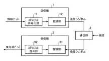
図1はこの発明の実施の形態1による軟判定値生成装置を適用する通信システムを示す構成図である。
図1において、送信機1は誤り訂正符号化部11と変調部12から構成されており、送信対象の情報を示す情報ビットの系列(以下、「情報ビット系列」と称する)から送信シンボルを生成し、通信路2を介して、その送信シンボルを受信機3に送信する。
誤り訂正符号化部11は情報ビット系列からパリティビットと呼ばれるビット系列(以下、「パリティビット系列」と称する)を生成し、その情報ビット系列とパリティビット系列を出力する処理を実施する。
変調部12は指定された多値変調の変調方式が示す規則にしたがって、誤り訂正符号化部11から出力された情報ビット系列及びパリティビット系列に対応するI−ch(同相成分)及びQ−ch(直交成分)からなる二次元平面上の座標(I−ch及びQ−chの座標)を決定し、その座標に送信シンボルをマッピングする処理を実施する。Hereinafter, in order to explain the present invention in more detail, modes for carrying out the present invention will be described with reference to the accompanying drawings.
1 is a block diagram showing a communication system to which a soft decision value generating apparatus according to
In FIG. 1, a
The error correction encoding unit 11 generates a bit sequence called a parity bit (hereinafter referred to as “parity bit sequence”) from the information bit sequence, and performs a process of outputting the information bit sequence and the parity bit sequence.
The
送信シンボルは、いわゆる電気信号に限るものではなく、光信号や電波などであってもよい。
送信シンボルは、通信路2を通って受信機3まで伝送されるが、通信路2で雑音の影響を受けるため、受信機3により受信された受信シンボルの座標が、送信シンボルの座標と異なっていることがある。The transmission symbol is not limited to a so-called electric signal, and may be an optical signal or a radio wave.
The transmission symbol is transmitted to the
受信機3は復調部31及び誤り訂正復号部32から構成されており、通信路2で雑音の影響を受けている受信シンボルを受信すると、誤りが生じている情報ビット系列を訂正し、誤り訂正後の情報ビット系列(復号後ビット)を出力する。
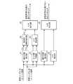
復調部31は図2の軟判定値生成装置を実装しており、受信シンボルのI−ch及びQ−chの座標から、受信シンボルを構成する各ビットの対数尤度比であるLLR(Log−Likelihood Ratio)を算出する処理を実施する。
ここでは、復調部31が軟判定値生成装置を実装してものを説明するが、その軟判定値生成装置の他に、例えば、等化器などが実装されているものであってもよい。等化器などは軟判定値生成装置の前段に設置されることが多い。
誤り訂正復号部32は復調部31により算出されたLLRを用いて軟判定復号を実施し、その復号結果である誤り訂正後の情報ビット系列(復号後ビット)を出力する。The
The
Here, a case where the
The error
図2はこの発明の実施の形態1による軟判定値生成装置を示す構成図である。
図2において、硬判定値算出部41は受信シンボルのI−ch及びQ−chの座標から硬判定値を算出する処理を実施する。なお、硬判定値算出部41は硬判定値算出手段を構成している。
LLR算出部42は受信シンボルのI−ch及びQ−chの座標から軟判定復号に用いるLLRを近似的に算出する処理を実施する。即ち、I−ch及びQ−chの座標からLLRの近似値を算出する処理を実施する。なお、LLR算出部42は近似値算出手段を構成している。
LLR補正部43はLLR算出部42により算出されたLLRの符号ビットが硬判定値算出部41により算出された硬判定値と矛盾している場合、そのLLRの符号ビットを反転し、符号ビット反転後のLLRを軟判定値として誤り訂正復号部32に出力する処理を実施する。なお、LLR補正部43は近似値補正手段を構成している。2 is a block diagram showing a soft decision value generation apparatus according to
In FIG. 2, the hard decision
The
The
図2の例では、軟判定値生成装置の構成要素である硬判定値算出部41、LLR算出部42及びLLR補正部43のそれぞれが専用のハードウェア(例えば、CPUを実装している半導体集積回路、あるいは、ワンチップマイコンなど)から構成されているものを想定しているが、軟判定値生成装置がコンピュータで構成されていてもよい。
軟判定値生成装置をコンピュータで構成する場合、硬判定値算出部41、LLR算出部42及びLLR補正部43の処理内容を記述しているプログラムをコンピュータのメモリに格納し、当該コンピュータのCPUが当該メモリに格納されているプログラムを実行するようにすればよい。
図3はこの発明の実施の形態1による軟判定値生成装置の処理内容(軟判定値生成方法)を示すフローチャートである。In the example of FIG. 2, each of the hard decision
When the soft decision value generation device is configured by a computer, a program describing the processing contents of the hard decision
FIG. 3 is a flowchart showing the processing contents (soft decision value generation method) of the soft decision value generation device according to
次に動作について説明する。
送信機1の誤り訂正符号化部11は、情報ビット系列を入力すると、その情報ビット系列からパリティビットと呼ばれるパリティビット系列を生成し、その情報ビット系列とパリティビット系列を変調部12に出力する。
送信機1の変調部12は、誤り訂正符号化部11から情報ビット系列とパリティビット系列を受けると、予め指定された多値変調の変調方式が示す規則にしたがって、その情報ビット系列及びパリティビット系列に対応する二次元平面上のI−ch及びQ−chの座標を決定し、その座標に送信シンボルをマッピングする。
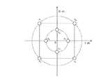
ここで、図4及び図5は変調方式が8QAMである場合のコンステレーションマッピングの例を示す説明図である。図4及び図5において、s0〜s7は送信シンボルを示している。
ここでは、変調方式が8QAMである場合を例示しているが、変調方式が8QAMに限るものでないことは言うまでもない。Next, the operation will be described.
When the information bit sequence is input, the error correction encoding unit 11 of the
When receiving the information bit sequence and the parity bit sequence from the error correction encoding unit 11, the
Here, FIGS. 4 and 5 are explanatory diagrams showing examples of constellation mapping when the modulation method is 8QAM. 4 and 5, s0 to s7 indicate transmission symbols.
Here, a case where the modulation scheme is 8QAM is illustrated, but it goes without saying that the modulation scheme is not limited to 8QAM.
変調部12によりマッピングされた送信シンボルは、通信路2を通って受信機3に伝送されるが、通信路2で雑音の影響を受けるため、受信機3により受信された受信シンボルの座標が、送信シンボルの座標と異なっていることがある。 The transmission symbol mapped by the
受信機3の復調部31は、通信路2で雑音の影響を受けている受信シンボルを受信すると、その受信シンボルのI−ch及びQ−chの座標から、受信シンボルを構成する各ビットの対数尤度比であるLLRを算出する。
以下、復調部31の処理内容を具体的に説明する。
まず、復調部31の硬判定値算出部41は、受信シンボルのI−ch及びQ−chの座標から硬判定値を算出する(図3のステップST1)。
硬判定値の算出処理は公知の技術であるため詳細な説明を省略するが、例えば、送信シンボルが取り得る全てのI−ch及びQ−chの座標の中で、受信シンボルのI−ch及びQ−chの座標と最も近い送信シンボルの座標を特定し、最も近い送信シンボルに割り当てられているビットの値を硬判定値とする方法などがある。When the
Hereinafter, the processing content of the
First, the hard decision
The hard decision value calculation process is a well-known technique and will not be described in detail. For example, among all the I-ch and Q-ch coordinates that can be taken by the transmission symbol, the received symbol I-ch and There is a method in which the coordinate of the transmission symbol closest to the Q-ch coordinate is specified, and the value of the bit assigned to the closest transmission symbol is used as a hard decision value.
LLR算出部42は、受信シンボルのI−ch及びQ−chの座標から、軟判定復号に用いるLLRを近似的に算出する。即ち、I−ch及びQ−chの座標からLLRの近似値を算出する(ステップST2)。
正確なLLRを算出するには、上記の式(1)を用いるのがよいが、上述したように大きな演算量が必要になる。
そこで、LLR算出部42では、演算量を削減するために、上記の式(2)を用いることで、LLRを近似的に算出する。
なお、LLRを近似的に算出する方法として、式(2)を用いる方法以外に、受信シンボルに近い送信シンボルを探さずに、その他の基準で送信シンボルを選び、その送信シンボルに基づいて近似的にLLRを算出する方法もある。
また、I−ch及びQ−chの座標とLLRの対応関係を記録しているルックアップテーブルを参照して、I−ch及びQ−chの座標に対応するLLRを取得する方法などもある。
ここで、LLRは、その符号ビットが、ビットの値が“0”であるのか、“1”であるのかを表しており、LLRの絶対値が信頼度を表している。The
In order to calculate an accurate LLR, it is preferable to use the above formula (1), but a large amount of computation is required as described above.
Therefore, the
Note that, as a method of calculating the LLR approximately, in addition to the method using the equation (2), a transmission symbol is selected based on other criteria without searching for a transmission symbol close to the reception symbol, and an approximation is performed based on the transmission symbol. There is also a method for calculating the LLR.
There is also a method of acquiring an LLR corresponding to the coordinates of the I-ch and Q-ch by referring to a lookup table that records the correspondence between the coordinates of the I-ch and Q-ch and the LLR.
Here, the LLR indicates whether the sign bit is “0” or “1”, and the absolute value of the LLR indicates the reliability.
LLR補正部43は、硬判定値算出部41が硬判定値を算出し、LLR算出部42がLLRを近似的に算出すると、その硬判定値とLLRの符号ビットとの間に矛盾が生じているか否かを判定する(ステップST3)。
例えば、LLRの符号ビットが正であるときビットの値が“0”であることを表し、LLRの符号ビットが負であるときビットの値が“1”であることを表している場合において、LLRの符号ビットが正で硬判定値が“1”であれば矛盾が生じている。また、LLRの符号ビットが負で硬判定値が“0”であれば矛盾が生じている。When the hard decision
For example, when the LLR sign bit is positive, the bit value is “0”, and when the LLR sign bit is negative, the bit value is “1”. If the sign bit of the LLR is positive and the hard decision value is “1”, a contradiction occurs. Further, if the sign bit of the LLR is negative and the hard decision value is “0”, a contradiction occurs.
ここでは、LLRの符号ビットが正であるときビットの値が“0”であることを表し、LLRの符号ビットが負であるときビットの値が“1”であることを表している場合を示したが、これは一例に過ぎず、LLRの符号ビットが正であるときビットの値が“1”であることを表し、LLRの符号ビットが負であるときビットの値が“0”であることを表しているものであってもよい。 Here, when the sign bit of the LLR is positive, the bit value is “0”, and when the sign bit of the LLR is negative, the bit value is “1”. Although shown, this is only an example. When the sign bit of the LLR is positive, the bit value is “1”, and when the sign bit of the LLR is negative, the bit value is “0”. It may represent something.
LLR補正部43は、硬判定値とLLRの符号ビットとの間に矛盾が生じている場合、そのLLRの符号ビットを反転し、符号ビット反転後のLLRを軟判定値として誤り訂正復号部32に出力する(ステップST4)。
即ち、LLR補正部43は、LLRの符号ビットが正であるとき、硬判定値が“1”であるために矛盾が生じていれば、LLRの符号ビットを負に反転して、負の符号ビットと絶対値からなるLLRを軟判定値として誤り訂正復号部32に出力する。
また、LLRの符号ビットが負であるとき、硬判定値が“0”であるために矛盾が生じていれば、LLRの符号ビットを正に反転して、正の符号ビットと絶対値からなるLLRを軟判定値として誤り訂正復号部32に出力する。
なお、符号ビット反転後のLLRを軟判定値として出力する際、LLRの絶対値(信頼度)については変更してもよいし、変更しなくてもよいが、後段の誤り訂正復号部32での誤り訂正復号性能が高まるようにするのが望ましい。
例えば、LLRの絶対値を最小値にすると、軟判定復号の性能が高くなる傾向がある。When there is a contradiction between the hard decision value and the LLR code bit, the
That is, when the LLR sign bit is positive, the
If the LLR sign bit is negative and the hard decision value is "0" and there is a contradiction, the LLR sign bit is inverted to be positive and consists of a positive sign bit and an absolute value. The LLR is output to the error
Note that when the LLR after the sign bit inversion is output as a soft decision value, the absolute value (reliability) of the LLR may or may not be changed. It is desirable to improve the error correction decoding performance.
For example, when the absolute value of the LLR is set to the minimum value, the performance of soft decision decoding tends to increase.
LLR補正部43は、硬判定値とLLRの符号ビットとの間に矛盾が生じていない場合、LLR算出部42により近似的に算出されたLLRを軟判定値として誤り訂正復号部32に出力する(ステップST5)。 When there is no contradiction between the hard decision value and the LLR code bit, the
誤り訂正復号部32は、復調部31から軟判定値を受けると、その軟判定値を用いて軟判定復号を実施し、その復号結果である誤り訂正後の情報ビット系列(復号後ビット)を出力する。
軟判定値を用いる軟判定復号の処理自体は、公知の技術であるため詳細な説明を省略する。When receiving the soft decision value from the
Since the soft decision decoding process using the soft decision value is a known technique, detailed description thereof is omitted.
以上で明らかなように、この実施の形態1によれば、多値変調が施されている受信シンボルのI−ch及びQ−chの座標から硬判定値を算出する硬判定値算出部41と、受信シンボルのI−ch及びQ−chの座標からLLRを近似的に算出するLLR算出部42とを設け、LLR補正部43が、LLR算出部42により算出されたLLRの符号ビットが硬判定値算出部41により算出された硬判定値と矛盾している場合、そのLLRの符号ビットを反転し、符号ビット反転後のLLRを軟判定値として誤り訂正復号部32に出力するように構成したので、近似精度が高いLLRを小さな演算量で算出することができる効果を奏する。
即ち、この実施の形態1によれば、LLR算出部42がLLRを近似的に算出することで、LLRの演算量を削減しているが、低演算量で算出可能な硬判定値を用いて、LLRを補正しているので、LLRの近似精度を高めることができる。このため、近似精度が高いLLRを小さな演算量で算出することができる。As is apparent from the above, according to the first embodiment, the hard decision
That is, according to the first embodiment, the
この実施の形態1では、変調方式が8QAMである例を示したが、変調多値度が2の奇数乗のQAMやAPSKなどの変調方式が用いられる場合、一般的には、受信シンボルを構成する各ビットに対するLLRが、I−ch座標とQ−ch座標の双方に依存するため、高精度なLLRの近似値を算出するには大きな演算量が必要になる。
この実施の形態1では、変調多値度が2の奇数乗のQAMやAPSKなどの変調方式が用いられる場合でも、演算量を削減することができるようにするため、LLR算出部42は、変調多値度が2の奇数乗のQAMやAPSKなどの変調方式で受信シンボルが変調されている場合、その受信シンボルの座標のうち、I−chの座標又はQ−chの座標のいずれか一方だけを用いて、LLRの近似値を算出するようにする。In the first embodiment, an example in which the modulation scheme is 8QAM has been shown. However, when a modulation scheme such as QAM or APSK having an odd number of modulation multivalues of 2 is used, a reception symbol is generally configured. Since the LLR for each bit depends on both the I-ch coordinate and the Q-ch coordinate, a large amount of calculation is required to calculate an approximate value of the LLR with high accuracy.
In the first embodiment, even when a modulation scheme such as QAM or APSK with an odd power of 2 is used, the
I−chの座標だけを用いて、LLRの近似値を算出する場合、例えば、Q−chの座標を0としてLLRの近似値を算出する。
また、Q−chの座標だけを用いて、LLRの近似値を算出する場合、例えば、I−chの座標を0としてLLRの近似値を算出する。
これにより、変調多値度が2の奇数乗のQAMやAPSKなどの変調方式が用いられる場合でも、演算量を削減することができる。この場合も、LLR補正部43が、低演算量で算出可能な硬判定値を用いて、LLRを補正しているので、LLRの近似精度を高めることができる。When calculating the approximate value of the LLR using only the coordinates of the I-ch, for example, the approximate value of the LLR is calculated by setting the coordinate of the Q-ch to 0.
Further, when calculating the approximate value of LLR using only the coordinates of Q-ch, for example, the approximate value of LLR is calculated by setting the coordinate of I-ch to 0.
Thereby, even when a modulation scheme such as QAM or APSK with an odd power of 2 is used, the amount of calculation can be reduced. Also in this case, since the
実施の形態2.
図6はこの発明の実施の形態2による軟判定値生成装置を示す構成図であり、図において、図1と同一符号は同一または相当部分を示すので説明を省略する。
ビット幅削減部44は例えばCPUを実装している半導体集積回路、あるいは、ワンチップマイコンなどから構成されており、受信シンボルのI−ch及びQ−chの座標を示すディジタルデータのビット幅を削減し、ビット幅削減後の受信シンボルのI−ch及びQ−chの座標をLLR算出部42に出力する処理を実施する。なお、ビット幅削減部44はビット幅削減手段を構成している。Embodiment 2. FIG.
6 is a block diagram showing a soft decision value generation apparatus according to Embodiment 2 of the present invention. In the figure, the same reference numerals as those in FIG.
The bit
上記実施の形態1では、LLR算出部42が受信シンボルのI−ch及びQ−chの座標からLLRを近似的に算出することで、演算量を削減するものを示したが、この実施の形態2では、更に演算量を削減するために、ビット幅削減部44を実装している。
ビット幅削減部44は、受信シンボルのI−ch及びQ−chの座標を受けると、I−ch及びQ−chの座標を示すディジタルデータのビット幅を削減し、ビット幅削減後の受信シンボルのI−ch及びQ−chの座標をLLR算出部42に出力する。
例えば、I−chの座標とQ−chの座標が、それぞれnビットのディジタルデータで入力された場合、それらのディジタルデータのビット幅をmビット(m<n)に削減する。In the first embodiment, the
Upon receiving the I-ch and Q-ch coordinates of the received symbol, the bit
For example, when the coordinates of I-ch and the coordinates of Q-ch are input as n-bit digital data, the bit width of these digital data is reduced to m bits (m <n).
ビット幅を削減する方法としては、I−ch及びQ−chの座標を示すディジタルデータの下位(n−m)ビットを削るようにしてもよいし、クリップ処理によって上位(n−m)ビットを削減するようにしてもよい。
I−ch及びQ−chの座標における座標値x(−2n≦x<2n−1)に対して、下記の式(4)に示すように、(n−m)ビット削減後の座標値yを算出するようにしてもよい。
・x≧0の場合
With respect to the coordinate value x (−2n ≦ x <2n−1) in the coordinates of I-ch and Q-ch, as shown in the following equation (4), the coordinate value y after (nm) bit reduction May be calculated.
・ When x ≧ 0
LLR算出部42は、ビット幅削減部44からビット幅削減後の受信シンボルのI−ch及びQ−chの座標を受けると、上記実施の形態1と同様に、その受信シンボルのI−ch及びQ−chの座標からLLRを近似的に算出するが、ビット幅が削減されているため、LLRの近似算出処理の演算量を大きく削減することができる。
例えば、I−ch及びQ−chの座標とLLRの対応関係を記録しているルックアップテーブルを参照して、I−ch及びQ−chの座標に対応するLLRを取得する方法を用いる場合、仮に、I−ch及びQ−chの座標を示すディジタルデータのビット幅を1ビット削減したとすると、ルックアップテーブルのアドレス幅を2ビット削減することができるため、ルックアップテーブルのサイズを1/4に削減することができる。When receiving the I-ch and Q-ch coordinates of the received symbol after the bit width reduction from the bit
For example, when using a method of acquiring an LLR corresponding to the coordinates of the I-ch and Q-ch with reference to a lookup table that records the correspondence between the coordinates of the I-ch and Q-ch and the LLR, If the bit width of the digital data indicating the coordinates of I-ch and Q-ch is reduced by 1 bit, the address width of the lookup table can be reduced by 2 bits. It can be reduced to 4.
なお、ビット幅削減部44により削減されるビット幅を大きくして、I−ch及びQ−chの座標を示すディジタルデータのビット幅を極めて小さくすると、LLR算出部42により算出されるLLRの近似精度が大きく劣化して、LLR補正部43で補正を行っても近似精度が十分に得られないことがある。
しかし、このような状況が発生するのは、I−ch及びQ−chの座標を示すディジタルデータのビット幅を2ビットにするなど、極めて小さいビット幅に削減した場合に限られる。
変調方式の多値度にもよるが、ビット幅削減後のディジタルデータのビット幅が3ビット以上であれば、このような近似精度の大きな劣化は起こらない。ただし、変調方式の多値度が多くなればなるほど、ビット幅削減後のディジタルデータのビット幅を大きくする必要がある。When the bit width reduced by the bit
However, such a situation occurs only when the bit width of the digital data indicating the coordinates of the I-ch and Q-ch is reduced to an extremely small bit width such as 2 bits.
Although depending on the multi-level of the modulation method, if the bit width of the digital data after the bit width reduction is 3 bits or more, such a large deterioration of the approximation accuracy does not occur. However, as the multi-level of the modulation method increases, it is necessary to increase the bit width of the digital data after the bit width reduction.
復調部31では、上述したように、軟判定値生成装置のほかに、等化器などを実装していることがあるが、等化器などでは、受信シンボルのI−ch及びQ−chの座標として、大きなビット幅の座標を必要とする。
この実施の形態1におけるLLR算出部42は、通常、等化器などの後段に設置されるため、I−ch及びQ−chの座標のビット幅が大きいことが多い。したがって、ある程度のビット幅を削減しても、LLRの近似精度が大きく劣化することはない。
削減するビット幅は、シミュレーションなどによって誤り訂正復号部32の性能評価を実施し、誤り訂正性能が高くなる値とするのが望ましい。また、ビット削減によって削減される演算量と回路規模を計りながら決定するのが望ましい。
なお、ビット幅削減に伴うLLR算出部42でのLLRの近似算出処理の演算量の削減量は、ビット幅削減部44によるビット幅削減処理の演算量より大きいので、軟判定値生成装置全体の演算量は小さくなる。したがって、上記実施の形態1より、演算量を小さくすることができるとともに、より回路の小型化を図ることができる。As described above, the
Since the
The bit width to be reduced is preferably set to a value that improves the error correction performance by performing performance evaluation of the error
Note that the amount of calculation of the LLR approximate calculation processing in the
実施の形態3.
図7はこの発明の実施の形態3による軟判定値生成装置を示す構成図である。
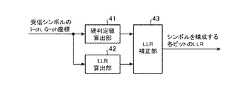
図3において、硬判定値算出部51は受信シンボルのI−ch及びQ−chの座標から硬判定値HJ1を算出するとともに、その受信シンボルより一時刻前の受信シンボルである基準シンボルのI−ch及びQ−chの座標から硬判定値HJ2を算出する処理を実施する。なお、硬判定値算出部51は硬判定値算出手段を構成している。
硬判定差動復号部52は硬判定値算出部51により算出された硬判定値HJ1,HJ2を用いて、硬判定の差動復号を実施して、差動復号後の硬判定値HJ3を算出する処理を実施する。なお、硬判定差動復号部52は硬判定差動復号手段を構成している。
FIG. 7 is a block diagram showing a soft decision value generation apparatus according to
In FIG. 3, a hard decision
The hard decision
ビット幅削減部53は受信シンボルのI−ch及びQ−chの座標を示すディジタルデータのビット幅を削減するとともに、基準シンボルのI−ch及びQ−chの座標を示すディジタルデータのビット幅を削減し、ビット幅削減後の受信シンボルのI−ch及びQ−chの座標及びビット幅削減後の基準シンボルのI−ch及びQ−chの座標をLLR算出部54に出力する処理を実施する。なお、ビット幅削減部53はビット幅削減手段を構成している。 The bit
LLR算出部54はビット幅削減部53から出力されたビット幅削減後の受信シンボルのI−ch及びQ−chの座標と、ビット幅削減後の基準シンボルのI−ch及びQ−chの座標とから、軟判定復号に用いるLLRを近似的に算出する処理を実施する。なお、LLR算出部54は近似値算出手段を構成している。
LLR補正部55はLLR算出部54により算出されたLLRの符号ビットが硬判定差動復号部52により算出された差動復号後の硬判定値HJ3と矛盾している場合、そのLLRの符号ビットを反転し、符号ビット反転後のLLRを軟判定値として誤り訂正復号部32に出力する処理を実施する。なお、LLR補正部55は近似値補正手段を構成している。The
When the LLR code bit calculated by the
図7の例では、軟判定値生成装置の構成要素である硬判定値算出部51、硬判定差動復号部52、ビット幅削減部53、LLR算出部54及びLLR補正部55のそれぞれが専用のハードウェア(例えば、CPUを実装している半導体集積回路、あるいは、ワンチップマイコンなど)から構成されているものを想定しているが、軟判定値生成装置がコンピュータで構成されていてもよい。
軟判定値生成装置をコンピュータで構成する場合、硬判定値算出部51、硬判定差動復号部52、ビット幅削減部53、LLR算出部54及びLLR補正部55の処理内容を記述しているプログラムをコンピュータのメモリに格納し、当該コンピュータのCPUが当該メモリに格納されているプログラムを実行するようにすればよい。
図8はこの発明の実施の形態3による軟判定値生成装置の処理内容(軟判定値生成方法)を示すフローチャートである。In the example of FIG. 7, each of the hard decision
When the soft decision value generation device is configured by a computer, the processing contents of the hard decision
FIG. 8 is a flowchart showing the processing contents (soft decision value generation method) of the soft decision value generation device according to
次に動作について説明する。
この実施の形態3では、受信シンボルが差動符号化を伴う変調方式で変調されているものとする。
硬判定値算出部51は、送信機1の変調部12で差動符号化されている受信シンボルを受信すると、図2の硬判定値算出部41と同様に、その受信シンボルのI−ch及びQ−chの座標から硬判定値HJ1を算出する(図8のステップST11)。
また、硬判定値算出部51は、その受信シンボルより一時刻前の受信シンボルである基準シンボルを受信すると、受信シンボルの場合と同様に、その基準シンボルのI−ch及びQ−chの座標から硬判定値HJ2を算出する(ステップST11)。Next, the operation will be described.
In the third embodiment, it is assumed that the received symbol is modulated by a modulation scheme with differential encoding.
When the hard decision
Further, when the hard decision
ビット幅削減部53は、送信機1の変調部12で差動符号化されている受信シンボルを受信すると、図6のビット幅削減部44と同様に、その受信シンボルのI−ch及びQ−chの座標を示すディジタルデータのビット幅を削減する(ステップST12)。
また、ビット幅削減部53は、基準シンボルを受信すると、受信シンボルの場合と同様に、その基準シンボルのI−ch及びQ−chの座標を示すディジタルデータのビット幅を削減する(ステップST12)。When the bit
Further, when receiving the reference symbol, the bit
ビット幅削減部53は、受信シンボルの座標に対するビット幅の削減処理と、基準シンボルの座標に対するビット幅の削減処理とを独立に実施するが、基準シンボルの座標に応じて、基準シンボルと受信シンボルを同じ角度で回転することで、ビット精度を減らさずにビット幅を削減することができる場合がある。
基準シンボルの位相(シンボルと原点を結ぶ線分とI−ch軸との角度)と、送信シンボルの位相との差によって差動符号化が施されている場合、その位相差を変えずに基準シンボルと受信シンボルの座標に回転などの変換を施すようにしてもよい。
例えば、送信機1の変調部12が、基準シンボルと送信シンボルの位相差を90度にして差動符号化を行う場合、受信した基準シンボルと受信シンボルに対して、基準シンボルが第一象限になるように回転する。その際、上述したように、受信シンボルも同じ角度で回転を施せば、位相差が保たれるため、LLRの算出に支障が生じることはない。The bit
If differential encoding is performed by the difference between the phase of the reference symbol (the angle between the line connecting the symbol and the origin and the I-ch axis) and the phase of the transmission symbol, the reference is made without changing the phase difference. You may make it perform conversion, such as rotation, to the coordinate of a symbol and a received symbol.
For example, when the
回転後の基準シンボルは必ず第一象限になり、I−chの座標とQ−chの座標の正負を表す符号ビットは必ず0になるため、符号ビットを削減しても差し支えない。このため、ビット精度を落とさずに、基準シンボルのI−chの座標とQ−chの座標を1ビットずつ削減することができる。
このような差動符号化が施された変調方式としては、例えば、差動符号化QPSK(DQPSK)がある。また、BPSK、8QAMや16QAMなどでも、90度又は180度単位での差動符号化方法があり、本操作によるビット幅削減が可能である。Since the reference symbol after rotation is always in the first quadrant, and the sign bit indicating the sign of the I-ch coordinate and the Q-ch coordinate is always 0, the sign bit may be reduced. For this reason, it is possible to reduce the I-ch coordinates and the Q-ch coordinates of the reference symbol one bit at a time without reducing the bit accuracy.
As a modulation scheme subjected to such differential encoding, for example, there is differential encoding QPSK (DQPSK). Also, BPSK, 8QAM, 16QAM, and the like have a differential encoding method in units of 90 degrees or 180 degrees, and the bit width can be reduced by this operation.
硬判定差動復号部52は、硬判定値算出部51が硬判定値HJ1,HJ2を算出すると、送信機1の変調部12で行われる差動符号化のルールにしたがって、その硬判定値HJ1,HJ2を用いる硬判定の差動復号を実施することで、差動復号後の硬判定値HJ3を算出する(ステップST13)。
例えば、変調部12が、基準シンボルの位相と、送信するビット列との関係に基づいて、送信シンボルの位相を決定する場合には、受信シンボルと基準シンボルとの位相差から差動復号を行うことができる。ビット幅削減部53でのビット幅の削減処理で説明したような回転を施してから復号することもできる。
いずれにしても、送信機1の変調部12で行う処理と齟齬がない差動復号方法を用いれば本構成が実現可能である。硬判定の差動復号は、硬判定で処理を行うため、演算量は小さい。特に、LLRの算出と比べて問題とならない程、演算量が小さい。When the hard decision
For example, when the
In any case, this configuration can be realized by using a differential decoding method that is similar to the processing performed by the
LLR算出部54は、ビット幅削減部53からビット幅削減後の受信シンボルのI−ch及びQ−chの座標と、ビット幅削減後の基準シンボルのI−ch及びQ−chの座標とを受けると、ビット幅削減後の受信シンボルのI−ch及びQ−chの座標と、ビット幅削減後の基準シンボルのI−ch及びQ−chの座標とから、軟判定復号に用いるLLRを近似的に算出する(ステップST14)。
上記の式(3)を計算すれば、差動符号化されている受信シンボルであっても、LLRを算出することができるが、式(3)の演算量は膨大なため、LLRを近似的に算出する。The
If the above equation (3) is calculated, the LLR can be calculated even for a reception symbol that is differentially encoded. However, since the calculation amount of the equation (3) is enormous, the LLR is approximated. To calculate.
式(3)の具体的な近似演算方法の一例としては、上記の特許文献2に開示されているような方法がある。
また、特許文献2に開示されている方法と類似している方法として、送信シンボルの候補を絞り込むことでLLRを算出する方法を用いることもできる。
また、受信シンボル及び基準シンボルのI−ch及びQ−chの座標とLLRの対応関係を記録しているルックアップテーブルを参照して、I−ch及びQ−chの座標に対応するLLRを取得する方法などもある。その際、上記実施の形態1,2と比べて、ルックアップテーブルのアドレス幅が大きくなり、ルックアップテーブルのサイズが大きくなるが、ビット幅削減部53でビット幅の削減処理が実施されているため、テーブルサイズの増大を抑制することが可能である。
いずれの方法でも、後段のLLR補正部55による補正によって、一定の近似精度が得られる方法であれば適用可能である。As an example of a specific approximate calculation method of Expression (3), there is a method as disclosed in Patent Document 2 described above.
Further, as a method similar to the method disclosed in Patent Document 2, a method of calculating an LLR by narrowing down transmission symbol candidates can be used.
Also, an LLR corresponding to the coordinates of I-ch and Q-ch is obtained by referring to a look-up table that records the correspondence between the coordinates of I-ch and Q-ch of received symbols and reference symbols and the LLR. There is also a way to do it. At this time, the address width of the lookup table is increased and the size of the lookup table is increased as compared with the first and second embodiments, but the bit width reduction processing is performed by the bit
Any method can be applied as long as a certain approximate accuracy can be obtained by the correction by the
なお、LLR算出部54は、変調多値度が2の奇数乗のQAMやAPSKなどの変調方式が用いられる場合でも、演算量を削減することができるようにするため、図2のLLR算出部42と同様に、変調多値度が2の奇数乗のQAMやAPSKなどの変調方式で受信シンボルが変調されている場合、その受信シンボルの座標のうち、I−chの座標又はQ−chの座標のいずれか一方だけを用いて、LLRの近似値を算出するようにする。 Note that the
LLR補正部55は、硬判定差動復号部52が硬判定値HJ3を算出し、LLR算出部54がLLRを近似的に算出すると、その硬判定値HJ3とLLRの符号ビットとの間に矛盾が生じているか否かを判定する(ステップST15)。
例えば、LLRの符号ビットが正であるときビットの値が“0”であることを表し、LLRの符号ビットが負であるときビットの値が“1”であることを表している場合において、LLRの符号ビットが正で硬判定値が“1”であれば矛盾が生じている。また、LLRの符号ビットが負で硬判定値が“0”であれば矛盾が生じている。When the hard decision
For example, when the LLR sign bit is positive, the bit value is “0”, and when the LLR sign bit is negative, the bit value is “1”. If the sign bit of the LLR is positive and the hard decision value is “1”, a contradiction occurs. Further, if the sign bit of the LLR is negative and the hard decision value is “0”, a contradiction occurs.
ここでは、LLRの符号ビットが正であるときビットの値が“0”であることを表し、LLRの符号ビットが負であるときビットの値が“1”であることを表している場合を示したが、これは一例に過ぎず、LLRの符号ビットが正であるときビットの値が“1”であることを表し、LLRの符号ビットが負であるときビットの値が“0”であることを表しているものであってもよい。 Here, when the sign bit of the LLR is positive, the bit value is “0”, and when the sign bit of the LLR is negative, the bit value is “1”. Although shown, this is only an example. When the sign bit of the LLR is positive, the bit value is “1”, and when the sign bit of the LLR is negative, the bit value is “0”. It may represent something.
LLR補正部55は、硬判定値HJ3とLLRの符号ビットとの間に矛盾が生じている場合、そのLLRの符号ビットを反転し、符号ビット反転後のLLRを軟判定値として誤り訂正復号部32に出力する(ステップST16)。
即ち、LLR補正部55は、LLRの符号ビットが正であるとき、硬判定値が“1”であるために矛盾が生じていれば、LLRの符号ビットを負に反転して、負の符号ビットと絶対値からなるLLRを軟判定値として誤り訂正復号部32に出力する。
また、LLRの符号ビットが負であるとき、硬判定値が“0”であるために矛盾が生じていれば、LLRの符号ビットを正に反転して、正の符号ビットと絶対値からなるLLRを軟判定値として誤り訂正復号部32に出力する。
なお、符号ビット反転後のLLRを軟判定値として出力する際、LLRの絶対値(信頼度)については変更してもよいし、変更しなくてもよいが、後段の誤り訂正復号部32での誤り訂正復号性能が高まるようにするのが望ましい。
例えば、LLRの絶対値を最小値にすると、軟判定復号の性能が高くなる傾向がある。When there is a contradiction between the hard decision value HJ3 and the sign bit of the LLR, the
That is, when the LLR sign bit is positive, the
If the LLR sign bit is negative and the hard decision value is "0" and there is a contradiction, the LLR sign bit is inverted to be positive and consists of a positive sign bit and an absolute value. The LLR is output to the error
Note that when the LLR after the sign bit inversion is output as a soft decision value, the absolute value (reliability) of the LLR may or may not be changed. It is desirable to improve the error correction decoding performance.
For example, when the absolute value of the LLR is set to the minimum value, the performance of soft decision decoding tends to increase.
LLR補正部55は、硬判定値HJ3とLLRの符号ビットとの間に矛盾が生じていない場合、LLR算出部54により近似的に算出されたLLRを軟判定値として誤り訂正復号部32に出力する(ステップST17)。When there is no contradiction between the hard decision value HJ3 and the sign bit of the LLR, the
以上で明らかなように、この実施の形態3によれば、受信シンボルのI−ch及びQ−chの座標から硬判定値HJ1を算出するとともに、基準シンボルのI−ch及びQ−chの座標から硬判定値HJ2を算出する硬判定値算出部51と、硬判定値算出部51により算出された硬判定値HJ1,HJ2を用いて、硬判定の差動復号を実施して、差動復号後の硬判定値HJ3を算出する硬判定差動復号部52と、ビット幅削減部53から出力されたビット幅削減後の受信シンボルのI−ch及びQ−chの座標と、ビット幅削減後の基準シンボルのI−ch及びQ−chの座標とから、軟判定復号に用いるLLRを近似的に算出するLLR算出部54とを設け、LLR補正部55が、LLR算出部54により算出されたLLRの符号ビットが硬判定差動復号部52により算出された差動復号後の硬判定値HJ3と矛盾している場合、そのLLRの符号ビットを反転し、符号ビット反転後のLLRを軟判定値として誤り訂正復号部32に出力するように構成したので、差動符号化を伴う変調方式が用いられる場合でも、近似精度が高いLLRを小さな演算量で算出することができる効果を奏する。
なお、この実施の形態3では、上記の特許文献2とは異なり、QPSK以外の変調方式に対しても、低演算量で高精度なLLRを算出することができる。図4や図5に示す8QAMに対しても本効果が得られることは言うまでもない。As apparent from the above, according to the third embodiment, the hard decision value HJ1 is calculated from the coordinates of the I-ch and Q-ch of the received symbol, and the I-ch and Q-ch of the reference symbol are calculated. a hard decision
In the third embodiment, unlike the above-described Patent Document 2, it is possible to calculate a high-accuracy LLR with a low calculation amount even for a modulation scheme other than QPSK. Needless to say, this effect can be obtained for 8QAM shown in FIGS.
実施の形態4.
上記実施の形態3では、受信シンボルを構成する全てのビットが差動符号化されているものとして説明したが、受信シンボルを構成する複数のビットのうち、一部のビットだけに差動符号化される場合がある。
例えば、受信シンボルが3ビット構成であるとき、上位2ビットだけが差動符号化されていて、下位1ビットが差動符号化されていないような場合がある。
図9は受信シンボルを構成する複数のビットのうち、一部のビットだけに差動符号化される場合に適用可能な軟判定値生成装置を示している。Embodiment 4 FIG.
In the third embodiment, it has been described that all the bits constituting the reception symbol are differentially encoded. However, only a part of the plurality of bits constituting the reception symbol is differentially encoded. May be.
For example, when the received symbol has a 3-bit configuration, only the upper 2 bits are differentially encoded and the lower 1 bit is not differentially encoded.
FIG. 9 shows a soft decision value generation apparatus applicable when only a part of the plurality of bits constituting the received symbol is differentially encoded.
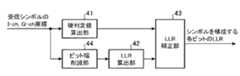
図9の軟判定値生成装置は、上記実施の形態3における図7の硬判定値算出部51、硬判定差動復号部52、ビット幅削減部53、LLR算出部54及びLLR補正部55の他に、上記実施の形態1における図2の硬判定値算出部41、LLR算出部42及びLLR補正部43を備えている。
この実施の形態4では、硬判定値算出部41、LLR算出部42及びLLR補正部43が対数尤度比算出手段を構成している。
図9の例では、ビット幅削減部44が実装されていないが、ビット幅削減部44がLLR算出部42の前段に配置されていてもよい。The soft decision value generation device of FIG. 9 includes the hard decision
In the fourth embodiment, the hard decision
In the example of FIG. 9, the bit
図9の軟判定値生成装置では、差動符号化されている受信シンボルのビットの座標については、基準シンボルの座標と一緒に、硬判定値算出部51及びビット幅削減部53が受け付ける。この場合、上記実施の形態3と同様の処理が実施される。
一方、差動符号化されていない受信シンボルのビットの座標については、硬判定値算出部51及びLLR算出部42が受け付ける。この場合、上記実施の形態1と同様の処理が実施される。
これにより、受信シンボルを構成する複数のビットのうち、一部のビットだけに差動符号化される場合でも、近似精度が高いLLRを小さな演算量で算出することができる効果を奏する。In the soft decision value generation apparatus of FIG. 9, the hard decision
On the other hand, the hard decision
As a result, even when only a part of the plurality of bits constituting the received symbol is differentially encoded, an LLR with high approximation accuracy can be calculated with a small amount of calculation.
なお、本願発明はその発明の範囲内において、各実施の形態の自由な組み合わせ、あるいは各実施の形態の任意の構成要素の変形、もしくは各実施の形態において任意の構成要素の省略が可能である。 In the present invention, within the scope of the invention, any combination of the embodiments, or any modification of any component in each embodiment, or omission of any component in each embodiment is possible. .
この発明に係る軟判定値生成装置は、近似値算出手段により算出された近似値の符号ビットが、硬判定値算出手段により算出された硬判定値と矛盾している場合、その近似値の符号ビットを反転し、符号ビット反転後の近似値を軟判定値として出力する近似値補正手段を備え、近似精度が高いLLRを小さな演算量で算出することができるため、ディジタル通信システムにおけるデータの誤り訂正に用いるのに好適である。 When the sign bit of the approximate value calculated by the approximate value calculating means is inconsistent with the hard decision value calculated by the hard decision value calculating means, the soft decision value generating apparatus according to the present invention is configured to sign the approximate value. An approximation value correcting means for inverting the bit and outputting the approximate value after the sign bit inversion as a soft decision value can be used to calculate an LLR with high approximation accuracy with a small amount of computation. It is suitable for use in correction.
1 送信機、2 通信路、3 受信機、11 誤り訂正符号化部、12 変調部、31 復調部、32 誤り訂正復号部、41 硬判定値算出部(硬判定値算出手段、対数尤度比算出手段)、42 LLR算出部(近似値算出手段、対数尤度比算出手段)、43 LLR補正部(近似値補正手段、対数尤度比算出手段)、44 ビット幅削減部(ビット幅削減手段)、51 硬判定値算出部(硬判定値算出手段)、52 硬判定差動復号部(硬判定差動復号手段)、53 ビット幅削減部(ビット幅削減手段)、54 LLR算出部(近似値算出手段)、55 LLR補正部(近似値補正手段)。 DESCRIPTION OF
Claims (9)
Translated fromJapanese前記受信シンボルの座標から軟判定復号に用いる対数尤度比の近似値を算出する近似値算出手段と、
前記近似値算出手段により算出された近似値の符号ビットが前記硬判定値算出手段により算出された硬判定値と矛盾している場合、前記近似値の符号ビットを反転し、符号ビット反転後の近似値を軟判定値として出力する近似値補正手段と
を備えた軟判定値生成装置。Hard decision value calculating means for calculating a hard decision value from the coordinates of the received symbol subjected to multi-level modulation;
Approximate value calculating means for calculating an approximate value of a log likelihood ratio used for soft decision decoding from the coordinates of the received symbol;
When the sign bit of the approximate value calculated by the approximate value calculating means is inconsistent with the hard decision value calculated by the hard decision value calculating means, the sign bit of the approximate value is inverted and the sign bit after A soft decision value generation device comprising: approximate value correction means for outputting an approximate value as a soft decision value.
前記硬判定値算出手段により前記受信シンボルの座標から算出された硬判定値と前記基準シンボルの座標から算出された硬判定値を用いて、硬判定の差動復号を実施して、差動復号後の硬判定値を算出する硬判定差動復号手段と、
前記受信シンボルの座標及び前記基準シンボルの座標から軟判定復号に用いる対数尤度比の近似値を算出する近似値算出手段と、
前記近似値算出手段により算出された近似値の符号ビットが前記硬判定差動復号手段により算出された差動復号後の硬判定値と矛盾している場合、前記近似値の符号ビットを反転し、符号ビット反転後の近似値を軟判定値として出力する近似値補正手段と
を備えた軟判定値生成装置。A hard decision value is calculated from the coordinates of a received symbol that has been subjected to multilevel modulation in a modulation scheme that performs differential encoding, and a hard decision value is derived from the coordinates of a reference symbol that is a received symbol one time before the received symbol. Hard decision value calculating means for calculating
Using the hard decision value calculated from the coordinates of the received symbol by the hard decision value calculation means and the hard decision value calculated from the coordinates of the reference symbol, differential decoding of hard decision is performed and differential decoding is performed. Hard decision differential decoding means for calculating a later hard decision value;
Approximate value calculating means for calculating an approximate value of a log likelihood ratio used for soft decision decoding from the coordinates of the received symbol and the coordinates of the reference symbol;
If the sign bit of the approximate value calculated by the approximate value calculation means is inconsistent with the hard decision value after differential decoding calculated by the hard decision differential decoding means, the sign bit of the approximate value is inverted. A soft decision value generation device comprising: approximate value correction means for outputting an approximate value after sign bit inversion as a soft decision value.
前記受信シンボルを構成するビットの座標から軟判定復号に用いる対数尤度比を算出する対数尤度比算出手段を備え、
前記差動符号化されている前記受信シンボルのビットの座標については、前記基準シンボルの座標と一緒に前記硬判定値算出手段及び前記近似値補正手段が受け付け、
前記差動符号化の対象外である前記受信シンボルのビットの座標については、前記対数尤度比算出手段が受け付けることを特徴とする請求項4記載の軟判定値生成装置。When only some of the plurality of bits constituting the received symbol are differentially encoded,
Log likelihood ratio calculating means for calculating a log likelihood ratio used for soft decision decoding from the coordinates of the bits constituting the received symbol;
For the coordinates of the bits of the received symbols that are differentially encoded, the hard decision value calculating means and the approximate value correcting means receive together with the coordinates of the reference symbols,
5. The soft decision value generation apparatus according to claim 4, wherein the log likelihood ratio calculation means accepts the coordinates of the bits of the received symbols that are not subjected to the differential encoding.
近似値算出手段が、前記受信シンボルの座標から軟判定復号に用いる対数尤度比の近似値を算出する近似値算出処理ステップと、
近似値補正手段が、前記近似値算出処理ステップで算出された近似値の符号ビットが前記硬判定値算出処理ステップで算出された硬判定値と矛盾している場合、前記近似値の符号ビットを反転し、符号ビット反転後の近似値を軟判定値として出力する近似値補正処理ステップと
を備えた軟判定値生成方法。A hard decision value calculating means for calculating a hard decision value from the coordinates of the received symbol subjected to multi-level modulation;
An approximate value calculation means for calculating an approximate value of a log likelihood ratio used for soft decision decoding from the coordinates of the received symbol;
When the approximate value correction means is inconsistent with the hard decision value calculated in the hard decision value calculation processing step, the sign bit of the approximate value calculated in the approximate value calculation processing step, A soft decision value generation method comprising: an approximate value correction processing step of inverting and outputting the approximate value after sign bit inversion as a soft decision value.
硬判定差動復号手段が、前記硬判定値算出処理ステップで前記受信シンボルの座標から算出された硬判定値と前記基準シンボルの座標から算出された硬判定値を用いて、硬判定の差動復号を実施して、差動復号後の硬判定値を算出する硬判定差動復号処理ステップと、
近似値算出手段が、前記受信シンボルの座標及び前記基準シンボルの座標から軟判定復号に用いる対数尤度比の近似値を算出する近似値算出処理ステップと、
近似値補正手段が、前記近似値算出処理ステップで算出された近似値の符号ビットが前記硬判定差動復号処理ステップで算出された差動復号後の硬判定値と矛盾している場合、前記近似値の符号ビットを反転し、符号ビット反転後の近似値を軟判定値として出力する近似値補正処理ステップと
を備えた軟判定値生成方法。The hard decision value calculating means calculates a hard decision value from the coordinates of a received symbol that has been subjected to multilevel modulation in a modulation scheme that performs differential encoding, and is a reference that is a received symbol one time before the received symbol. A hard decision value calculation processing step for calculating a hard decision value from the coordinates of the symbol;
The hard decision differential decoding means uses the hard decision value calculated from the coordinates of the received symbol and the hard decision value calculated from the coordinates of the reference symbol in the hard decision value calculation processing step to perform a hard decision differential. A hard-decision differential decoding processing step for performing decoding and calculating a hard-decision value after differential decoding;
An approximate value calculating means for calculating an approximate value of a log likelihood ratio used for soft decision decoding from the coordinates of the received symbol and the coordinates of the reference symbol;
When the approximate value correction means is inconsistent with the hard decision value after differential decoding calculated in the hard decision differential decoding processing step, the sign bit of the approximate value calculated in the approximate value calculation processing step, A soft decision value generation method comprising: an approximate value correction processing step for inverting the sign bit of the approximate value and outputting the approximate value after the sign bit inversion as a soft decision value.
Applications Claiming Priority (3)
| Application Number | Priority Date | Filing Date | Title |
|---|---|---|---|
| JP2014033108 | 2014-02-24 | ||
| JP2014033108 | 2014-02-24 | ||
| PCT/JP2014/077230WO2015125341A1 (en) | 2014-02-24 | 2014-10-10 | Soft decision value generation apparatus and soft decision value generation method |
Publications (2)
| Publication Number | Publication Date |
|---|---|
| JP5955481B2true JP5955481B2 (en) | 2016-07-20 |
| JPWO2015125341A1 JPWO2015125341A1 (en) | 2017-03-30 |
Family
ID=53877870
Family Applications (1)
| Application Number | Title | Priority Date | Filing Date |
|---|---|---|---|
| JP2016503929AActiveJP5955481B2 (en) | 2014-02-24 | 2014-10-10 | Soft decision value generation apparatus and soft decision value generation method |
Country Status (5)
| Country | Link |
|---|---|
| US (1) | US9735990B2 (en) |
| EP (1) | EP3113436B1 (en) |
| JP (1) | JP5955481B2 (en) |
| CN (1) | CN106063216B (en) |
| WO (1) | WO2015125341A1 (en) |
Families Citing this family (21)
| Publication number | Priority date | Publication date | Assignee | Title |
|---|---|---|---|---|
| CN109644010B (en) | 2016-09-01 | 2022-12-20 | 三菱电机株式会社 | Likelihood generating device, receiving device, likelihood generating method, and optical transmission system |
| US10340951B2 (en)* | 2017-09-13 | 2019-07-02 | Toshiba Memory Corporation | Soft decision LDPC decoder with improved LLR from neighboring bits |
| US10608673B2 (en) | 2017-12-22 | 2020-03-31 | Massachusetts Institute Of Technology | Decoding signals by guessing noise |
| US10944610B2 (en)* | 2017-12-22 | 2021-03-09 | Massachusetts Institute Of Technology | Decoding signals by guessing noise |
| US10404289B1 (en) | 2018-05-31 | 2019-09-03 | Inphi Corporation | Maximum likelihood error detection for decision feedback equalizers with PAM modulation |
| JP6633262B1 (en)* | 2019-03-11 | 2020-01-22 | 三菱電機株式会社 | Optical transmission device and likelihood generation circuit |
| US10872013B2 (en) | 2019-03-15 | 2020-12-22 | Toshiba Memory Corporation | Non volatile memory controller device and method for adjustment |
| GB201918218D0 (en) | 2019-12-11 | 2020-01-22 | Maynooth Univ | A method of decoding a codeword |
| CN113055319B (en)* | 2019-12-27 | 2022-02-25 | 华为技术有限公司 | Signal equalization method and device |
| US11431368B2 (en) | 2020-03-16 | 2022-08-30 | Massachusetts Institute Of Technology | Noise recycling |
| US11870459B2 (en) | 2020-06-08 | 2024-01-09 | Massachusetts Institute Of Technology | Universal guessing random additive noise decoding (GRAND) decoder |
| CN112003626B (en)* | 2020-08-31 | 2023-11-10 | 武汉梦芯科技有限公司 | LDPC decoding method, system and medium based on navigation message known bits |
| US11652567B2 (en)* | 2020-12-01 | 2023-05-16 | Micron Technology, Inc. | Replacement scheme for a pulse amplitude modulated bus |
| CN114726477B (en)* | 2021-01-04 | 2023-07-14 | 烽火通信科技股份有限公司 | Operation method of FEC soft decision signal and electronic equipment |
| US11463296B2 (en) | 2021-02-19 | 2022-10-04 | Ultralogic 6G, Llc | Error correction by merging copies of PAM-modulated 5G/6G messages |
| US11405131B2 (en) | 2021-02-19 | 2022-08-02 | Ultralogic 6G, Llc | AI-based error detection and correction in 5G/6G messaging |
| US11627592B2 (en) | 2021-04-05 | 2023-04-11 | Ultralogic 6G, Llc | Resource-efficient polling and scheduling of 5G/6G uplink messages |
| US11425744B2 (en) | 2021-04-05 | 2022-08-23 | Ultralogic 6G, Llc | Cascaded scheduling requests for resource-efficient 5G and 6G |
| CN115208726A (en)* | 2021-04-13 | 2022-10-18 | 中兴通讯股份有限公司 | Symbol transmitting method, symbol receiving method, transmitting apparatus, receiving apparatus, and storage medium |
| US12191995B2 (en)* | 2022-07-08 | 2025-01-07 | Nokia Solutions And Networks Oy | One-dimensional hard-input FEC receiver for digital communication |
| JP7699185B2 (en)* | 2023-11-06 | 2025-06-26 | Nttイノベーティブデバイス株式会社 | Symbol demapping circuit, receiving device, and symbol demapping method |
Citations (3)
| Publication number | Priority date | Publication date | Assignee | Title |
|---|---|---|---|---|
| JP2002330188A (en)* | 2001-03-12 | 2002-11-15 | Motorola Inc | Method and device for calculating log likelihood ratio of bits in qam signals |
| JP2007174057A (en)* | 2005-12-20 | 2007-07-05 | Nec Electronics Corp | Arithmetic circuit |
| WO2012070369A1 (en)* | 2010-11-26 | 2012-05-31 | 三菱電機株式会社 | Soft decision value generation circuit |
Family Cites Families (8)
| Publication number | Priority date | Publication date | Assignee | Title |
|---|---|---|---|---|
| GB0418263D0 (en)* | 2004-08-16 | 2004-09-15 | Ttp Communications Ltd | Soft decision enhancement |
| US20090041165A1 (en)* | 2005-10-05 | 2009-02-12 | Mitsubishi Electric Corporation | Receiver apparatus |
| US8675771B2 (en)* | 2006-09-29 | 2014-03-18 | Nec Corporation | Log likelihood ratio arithmetic circuit, transmission apparatus, log likelihood ratio arithmetic method, and program |
| US20090213953A1 (en)* | 2008-02-25 | 2009-08-27 | Legend Silicon Corp. | Bit Log Likelihood Ratio (LLR) Computation of a 32-QAM System |
| CN101237434B (en)* | 2008-03-10 | 2011-02-02 | 电子科技大学 | A soft judgement method for Graham M-PSK modulation |
| CN102307175A (en)* | 2011-10-08 | 2012-01-04 | 四川虹微技术有限公司 | Multicarrier system soft-decision method |
| US9184954B1 (en)* | 2014-07-02 | 2015-11-10 | Seagate Technology Llc | Systems and methods for directed soft data perturbation in layered decoding |
| US9432053B1 (en)* | 2014-07-07 | 2016-08-30 | Microsemi Storage Solutions (U.S.), Inc. | High speed LDPC decoder |
- 2014
- 2014-10-10WOPCT/JP2014/077230patent/WO2015125341A1/enactiveApplication Filing
- 2014-10-10JPJP2016503929Apatent/JP5955481B2/enactiveActive
- 2014-10-10CNCN201480075224.7Apatent/CN106063216B/enactiveActive
- 2014-10-10EPEP14883121.7Apatent/EP3113436B1/enactiveActive
- 2014-10-10USUS15/116,133patent/US9735990B2/enactiveActive
Patent Citations (3)
| Publication number | Priority date | Publication date | Assignee | Title |
|---|---|---|---|---|
| JP2002330188A (en)* | 2001-03-12 | 2002-11-15 | Motorola Inc | Method and device for calculating log likelihood ratio of bits in qam signals |
| JP2007174057A (en)* | 2005-12-20 | 2007-07-05 | Nec Electronics Corp | Arithmetic circuit |
| WO2012070369A1 (en)* | 2010-11-26 | 2012-05-31 | 三菱電機株式会社 | Soft decision value generation circuit |
Non-Patent Citations (2)
| Title |
|---|
| JPN6016017892; F. Tosato et al.,: 'Simplified soft-output demapper for binary interleaved COFDM with application to HIPERLAN/2' 2002.IEEE International Conference on Communications (ICC 2002) Volume:2, 2002, pp.664-668* |
| JPN6016017894; 杉原堅也、松本渉: '多値変調における硬判定フィードバックを用いた対数尤度比算出法' 電子情報通信学会総合大会講演論文集 2012 年 基礎・境界 , 20120306, p.158* |
Also Published As
| Publication number | Publication date |
|---|---|
| US20170134193A1 (en) | 2017-05-11 |
| US9735990B2 (en) | 2017-08-15 |
| EP3113436B1 (en) | 2020-03-11 |
| CN106063216B (en) | 2018-06-19 |
| JPWO2015125341A1 (en) | 2017-03-30 |
| CN106063216A (en) | 2016-10-26 |
| WO2015125341A1 (en) | 2015-08-27 |
| EP3113436A4 (en) | 2017-10-18 |
| EP3113436A1 (en) | 2017-01-04 |
Similar Documents
| Publication | Publication Date | Title |
|---|---|---|
| JP5955481B2 (en) | Soft decision value generation apparatus and soft decision value generation method | |
| KR102021314B1 (en) | Apparatus and method for soft-decision demodulating in Non-square Quadrature Amplitude Modulation | |
| KR100758306B1 (en) | Apparatus for Generating Soft Bit Metric and its method, and M-ary QAM receive system using it | |
| CN103250385B (en) | Soft decision value generation circuit | |
| US10033480B2 (en) | Wireless communication device and method | |
| JP2005503725A (en) | Apparatus and method for calculating input softness value of channel decoder in data communication system | |
| CN111277536A (en) | DVB-S2X system soft demapping method, digital signal processing system | |
| TWI433471B (en) | Siso decoder of (n, k) block code | |
| US20030138055A1 (en) | Decoder and decoding method | |
| KR101704096B1 (en) | Process for performing log-likelihood-ratio clipping in a soft-decision near-ml detector, and detector for doing the same | |
| KR100706618B1 (en) | Soft Decision Demapping Method Suitable for Higher-order Modulation for Iterative Decoder and Its Error Correction Device | |
| US9531577B2 (en) | Bit-likelihood calculating apparatus and bit-likelihood calculating method | |
| CN108781129A (en) | Log-likelihood calculations circuit, reception device and log-likelihood calculations method | |
| US20030112900A1 (en) | Demodulation apparatus and method in a communication system employing 8-ary PSK modulation | |
| JP6177141B2 (en) | Log likelihood ratio calculation device, log likelihood ratio calculation method, and log likelihood ratio calculation program | |
| KR101702235B1 (en) | Soft demapping method and apparatus for M-ary PSK and QAM schemes | |
| JP4212453B2 (en) | Likelihood calculation method and distributed calculation circuit | |
| US10142145B2 (en) | Wireless receiver | |
| JP6731771B2 (en) | Demapping processing circuit, chip, and receiving device | |
| US8640014B2 (en) | Soft bit metric generation | |
| JP3643348B2 (en) | Decoding device and decoding method | |
| JP2015041850A (en) | Soft decision value generator and receiver | |
| KR100903876B1 (en) | Method and apparatus for dividing received symbol signal modulated by phase shift method into bit information using bit symmetric gray code |
Legal Events
| Date | Code | Title | Description |
|---|---|---|---|
| TRDD | Decision of grant or rejection written | ||
| A975 | Report on accelerated examination | Free format text:JAPANESE INTERMEDIATE CODE: A971005 Effective date:20160511 | |
| A01 | Written decision to grant a patent or to grant a registration (utility model) | Free format text:JAPANESE INTERMEDIATE CODE: A01 Effective date:20160517 | |
| A61 | First payment of annual fees (during grant procedure) | Free format text:JAPANESE INTERMEDIATE CODE: A61 Effective date:20160614 | |
| R150 | Certificate of patent or registration of utility model | Ref document number:5955481 Country of ref document:JP Free format text:JAPANESE INTERMEDIATE CODE: R150 | |
| R250 | Receipt of annual fees | Free format text:JAPANESE INTERMEDIATE CODE: R250 | |
| R250 | Receipt of annual fees | Free format text:JAPANESE INTERMEDIATE CODE: R250 | |
| R250 | Receipt of annual fees | Free format text:JAPANESE INTERMEDIATE CODE: R250 | |
| R250 | Receipt of annual fees | Free format text:JAPANESE INTERMEDIATE CODE: R250 | |
| R250 | Receipt of annual fees | Free format text:JAPANESE INTERMEDIATE CODE: R250 | |
| R250 | Receipt of annual fees | Free format text:JAPANESE INTERMEDIATE CODE: R250 | |
| R250 | Receipt of annual fees | Free format text:JAPANESE INTERMEDIATE CODE: R250 |