JP5955170B2 - Display control apparatus, display control method, and program - Google Patents
Display control apparatus, display control method, and programDownload PDFInfo
- Publication number
- JP5955170B2 JP5955170B2JP2012196097AJP2012196097AJP5955170B2JP 5955170 B2JP5955170 B2JP 5955170B2JP 2012196097 AJP2012196097 AJP 2012196097AJP 2012196097 AJP2012196097 AJP 2012196097AJP 5955170 B2JP5955170 B2JP 5955170B2
- Authority
- JP
- Japan
- Prior art keywords
- image
- display
- display control
- detected
- moving body
- Prior art date
- Legal status (The legal status is an assumption and is not a legal conclusion. Google has not performed a legal analysis and makes no representation as to the accuracy of the status listed.)
- Active
Links
Images


Classifications
- G—PHYSICS
- G06—COMPUTING OR CALCULATING; COUNTING
- G06F—ELECTRIC DIGITAL DATA PROCESSING
- G06F3/00—Input arrangements for transferring data to be processed into a form capable of being handled by the computer; Output arrangements for transferring data from processing unit to output unit, e.g. interface arrangements
- G06F3/01—Input arrangements or combined input and output arrangements for interaction between user and computer
- G06F3/048—Interaction techniques based on graphical user interfaces [GUI]
- G06F3/0484—Interaction techniques based on graphical user interfaces [GUI] for the control of specific functions or operations, e.g. selecting or manipulating an object, an image or a displayed text element, setting a parameter value or selecting a range
- G06F3/04842—Selection of displayed objects or displayed text elements
- G—PHYSICS
- G06—COMPUTING OR CALCULATING; COUNTING
- G06T—IMAGE DATA PROCESSING OR GENERATION, IN GENERAL
- G06T11/00—2D [Two Dimensional] image generation
- H—ELECTRICITY
- H04—ELECTRIC COMMUNICATION TECHNIQUE
- H04N—PICTORIAL COMMUNICATION, e.g. TELEVISION
- H04N23/00—Cameras or camera modules comprising electronic image sensors; Control thereof
- H04N23/60—Control of cameras or camera modules
- H04N23/63—Control of cameras or camera modules by using electronic viewfinders
- H04N23/631—Graphical user interfaces [GUI] specially adapted for controlling image capture or setting capture parameters
- H—ELECTRICITY
- H04—ELECTRIC COMMUNICATION TECHNIQUE
- H04N—PICTORIAL COMMUNICATION, e.g. TELEVISION
- H04N23/00—Cameras or camera modules comprising electronic image sensors; Control thereof
- H04N23/60—Control of cameras or camera modules
- H04N23/63—Control of cameras or camera modules by using electronic viewfinders
- H04N23/633—Control of cameras or camera modules by using electronic viewfinders for displaying additional information relating to control or operation of the camera
- H04N23/635—Region indicators; Field of view indicators
- H—ELECTRICITY
- H04—ELECTRIC COMMUNICATION TECHNIQUE
- H04N—PICTORIAL COMMUNICATION, e.g. TELEVISION
- H04N23/00—Cameras or camera modules comprising electronic image sensors; Control thereof
- H04N23/60—Control of cameras or camera modules
- H04N23/66—Remote control of cameras or camera parts, e.g. by remote control devices
- H04N23/661—Transmitting camera control signals through networks, e.g. control via the Internet
- H—ELECTRICITY
- H04—ELECTRIC COMMUNICATION TECHNIQUE
- H04N—PICTORIAL COMMUNICATION, e.g. TELEVISION
- H04N23/00—Cameras or camera modules comprising electronic image sensors; Control thereof
- H04N23/60—Control of cameras or camera modules
- H04N23/62—Control of parameters via user interfaces
Landscapes
- Engineering & Computer Science (AREA)
- Multimedia (AREA)
- Signal Processing (AREA)
- Theoretical Computer Science (AREA)
- Human Computer Interaction (AREA)
- Physics & Mathematics (AREA)
- General Physics & Mathematics (AREA)
- General Engineering & Computer Science (AREA)
- Closed-Circuit Television Systems (AREA)
- Studio Devices (AREA)
- Controls And Circuits For Display Device (AREA)
Description
Translated fromJapanese本発明は表示制御装置、表示制御方法及びプログラムに関し、特に、移動体の認識を行なうことにより、所定の撮影を行ない、画像の表示又は送信を行なうために用いて好適な技術に関する。The present invention relates to a display controldevice , a display control method, and a program, and more particularly, to a technique suitable for performing predetermined photographing and displaying or transmitting an image by recognizing a moving body.
監視及びモニタリングカメラシステムでは映像解析技術を利用して、映像中の移動体を検出する技術がある。さらに、検出した被写体の移動体に対してラベルを付加することにより、映像中の移動体を常に捉えるように認識する技術が移動体追尾技術として知られている。これらの技術を利用して、特許文献1では、撮像した画像に移動体を検出すると、移動体を含む特定エリアの画像データのみ全画面映像データから抜き出して外部に送出する技術が開示されている。 In the surveillance and monitoring camera system, there is a technique for detecting a moving body in an image using an image analysis technique. Furthermore, a technique for recognizing a moving object in a video by always adding a label to the detected moving object is known as a moving object tracking technique. Using these techniques, Patent Document 1 discloses a technique in which when a moving body is detected in a captured image, only image data of a specific area including the moving body is extracted from the full-screen video data and transmitted to the outside. .
また、近年の高画質化が進んだことにより、デジタルカメラ、デジタルビデオカメラに搭載されている撮像素子にCMOSセンサが多く使われるようになった。CMOSセンサは、以前のCCDセンサと比較して、センサ内のアドレス回路により限定されるが、ある程度自由な読み出し制御が可能である。 In addition, with the recent improvement in image quality, CMOS sensors are often used for image sensors mounted on digital cameras and digital video cameras. Compared with the previous CCD sensor, the CMOS sensor is limited by an address circuit in the sensor, but it can perform a somewhat free reading control.
例えば、読み出しの領域指定を行なうことにより、不要な部分を読み飛ばすことや、数画素おきに読み出し間隔を指定することにより、読み出す画素数は減るが高速化を図ることができる。よって、これらの技術を利用すると、CMOSセンサで数画素おきに間引いて読み出す。そして、高速で撮像された映像に対して、移動体を検出させて、検出された移動体を追尾するように、領域指定で読み出し、高精細で撮像するようにすれば有効な撮像センサを構成することが可能となる。 For example, by designating a readout area, skipping unnecessary portions or designating readout intervals every several pixels can reduce the number of pixels to be read but increase the speed. Therefore, when these technologies are used, the CMOS sensor reads out data every several pixels. An effective image sensor can be constructed by detecting the moving object from the image captured at high speed, tracking the detected moving object, reading out the area, and capturing the image with high definition. It becomes possible to do.
撮像センサの画素数が多画素化した場合、前述のように、撮像センサからの撮像を、全画素範囲の間引き読み出しと、移動体の検出エリアの部分領域の読み出しを時分割で行なう場合。この場合に、検出される移動体の数が多くなるにつれて、撮像した映像をすべて表示したり、あるいは送信するデータは大容量化してくるため送信したりするのは困難となってくる。
本発明は前述の問題点に鑑み、撮像された被写体から検出される移動体の数が多くなった場合でも、複数の移動体の一覧リストおよびそれぞれの移動体が撮像されている位置情報を効率良く表示したり、送信したりできるようにすることを目的とする。When the number of pixels of the imaging sensor is increased, as described above, when imaging from the imaging sensor is read out in a time-division manner by reading out the entire pixel range and reading out a partial area of the detection area of the moving object. In this case, as the number of detected moving bodies increases, it becomes difficult to display all captured images or to transmit because the data to be transmitted has a large capacity.
In the present invention, in view of the above-described problems, even when the number of moving objects detected from an imaged subject increases, a list of a plurality of moving objects and position information where each moving object is imaged are efficiently used. The purpose is to be able to display and transmit well.
本発明の表示制御装置は、第1の時点において、入力される画像から移動体を検出する移動体検出手段によって第1の数の移動体が検出された場合、検出された移動体に対応する、前記第1の数の項目の一覧を表示手段に表示させ、第2の時点において、前記移動体検出手段によって前記第1の数とは異なる第2の数の移動体が検出された場合、検出された移動体に対応する、前記第2の数の項目の一覧を前記表示手段に表示させ、前記一覧から選択された項目に対応する、前記画像に含まれる一部の領域である部分領域の画像を前記表示手段に表示させる表示制御手段を有することを特徴とする。The display controlapparatus according to the present invention corresponds to the detected moving object whenthe first number of moving objects is detected by the moving object detecting unit that detects the moving object fromthe input imageat the first time point.A list of the first number of items is displayed on the display means, and a second number of moving bodies different from the first number are detected by the moving body detecting means at a second time point,A partial region that is a partial regionincluded in the image and that corresponds to the item selectedfrom the list, by causing the display unit to display a list of the second number of items corresponding to the detected moving object It has adisplay control means todisplay the image of the above on the display means.
本発明によれば、所望の移動体の映像を選択することが可能となり、効率よく移動体の映像の表示あるいは送信を行なうことができる。 ADVANTAGE OF THE INVENTION According to this invention, it becomes possible to select the image | video of a desired mobile body, and the video of a mobile body can be displayed or transmitted efficiently.
以下、添付の図面を参照して、本発明をその好適な実施形態に基づいて詳細に説明する。なお、以下の実施形態において示す構成は一例に過ぎず、本発明は図示された構成に限定されるものではない。 Hereinafter, the present invention will be described in detail based on preferred embodiments with reference to the accompanying drawings. The configurations shown in the following embodiments are merely examples, and the present invention is not limited to the illustrated configurations.
(第1の実施形態)
図1は、本発明が適用される撮像システムの構成例を示したブロック図である。
図1において、101は撮像センサ部で、撮像面に結像された光像を光電変換によりデジタル電気信号に変換するCMOSなどの撮像素子により構成される。102は現像処理部であり、撮像センサ部101から光電変換により得られたデジタル電気信号に対して、所定の画素補間や色変換処理を行ない、RGBあるいはYUVなどのコンポーネント方式のデジタル画像を生成する。(First embodiment)
FIG. 1 is a block diagram illustrating a configuration example of an imaging system to which the present invention is applied.
In FIG. 1,
また、現像処理部102では、現像を施した後のデジタル画像を用いて所定の演算処理を行ない、得られた演算結果に基づいてホワイトバランス、シャープネス、コントラスト、色変換などの画像処理を行なっている。 The
103は撮像センサ制御部で、移動体検出部104からの検出情報により、撮像センサ部101に対して、全画素範囲に対して数画素おきの間引き読み出しや、領域を指定した部分読み出しなどを行うような制御を行なう。
移動体検出部104は、現像処理部102で現像処理、画像処理を施されたデジタル画像に対して、撮影された被写体の移動体の検出を行なう。移動体検出の方法としては、背景差分、フレーム間差分、動きベクトルなど、どのような方法を用いてもよい。さらに、この移動体の一部をテンプレートとして記憶して移動体の追尾も行なうことができるものである。 The moving
105は描画表示処理部で、撮像センサ制御部103からの制御により描画表示処理を行なう。そして、撮像センサ部101から部分領域を読み出し撮像されて、現像処理部102で現像処理、画像処理を施されたデジタル画像に対して枠を表示し、適当な位置に配置された画面を作成するための適切な処理を行なう。さらに、移動体検出部104で検出、追尾された移動体のIDとともに一覧リストとその画面上の位置を表したグラフィック描写を前述の画面に重畳させる。 A drawing
106は操作部であり、移動体検出部104で検出、追尾された移動体の一覧リストからどの移動体に対して領域を指定した部分読み出しを行ない表示させるかの指示を行なう。操作入力の手段としては、例えば、リモコン、キーボードやマウスなどで行なう。107はディスプレイ装置であり、描画表示処理部105で作成された画面を表示させる。
前述の構成で、本実施形態の撮像システムの動作の詳細を説明する。
まず、最初は移動体検出部104が起動される前、あるいは移動体検出部104で被写体に移動体が検出されていない状態を通常状態とする。この通常状態では、撮像センサ制御部103は撮像センサ部101に対して全画素範囲で読み出しを行なう第1の撮像モードで動作するように制御を行なう。Details of the operation of the imaging system of the present embodiment having the above-described configuration will be described.
First, the normal state is set to a state where the moving
この通常状態では、被写体に移動体が検出されていないため、撮像して現像処理部102で現像処理、画像処理を行なう画像データ量として、処理する速度に余裕があれば全画素範囲の間引きなしで読み出しても構わない。しかし、ある程度の処理する速度を稼ぐ場合には、数画素おきに全画素範囲を間引いて読み出すようにする。 In this normal state, since no moving object is detected in the subject, the entire pixel range is not thinned out if there is a margin for the processing speed as the amount of image data to be imaged and subjected to development processing and image processing by the
この時、撮像センサ部101で撮像され、現像処理部102で現像処理、画像処理を施されたデジタル画像は移動体検出部104へ出力される。この撮像された映像において、被写体に移動体が検出されていなければ、移動体検出部104、描画表示処理部105を介して、そのままディスプレイ装置107に映像が表示される。 At this time, a digital image captured by the
次に、撮像センサ部101で撮像された被写体に移動体が検出された時の状態を説明する。
通常状態で、撮像センサ部101の全画素範囲で読み出し撮像されているときに、現像処理部102から移動体検出部104に入力された映像から、移動体検出部104が被写体に移動体を検出したとする。Next, a state when a moving body is detected in the subject imaged by the
In a normal state, the moving
被写体に移動体が検出されると、移動体検出部104はその移動体の追尾を行なうことで、識別子となるIDを付加し、そのIDとともに位置情報を含んだ検出情報の通知を撮像センサ制御部103と描画表示処理部105へ送る。このとき、撮像センサ部101に対して全画素範囲の間引きなしで読み出していた場合、撮像センサ制御部103は撮像センサ部101に対して全画素範囲の数画素おきの間引き読み出しを行なうように切り換え制御する。 When a moving body is detected in the subject, the moving
さらに、撮像センサ制御部103は、この位置情報を含んだ検出情報を基にターゲットとなる移動体に対して、撮像センサ部101で読み出す部分領域を設定し、撮像素子の一部の画素から画像データを読み出す第2の撮像モードで動作するように制御を行なう。第2の撮像モードで動作する場合においても、全画素範囲で読み出しを行なう第1の撮像モードと動作する場合と同様に、前述の全画素範囲の間引き読み出しと時分割で読み出す制御を行なう。検出された移動体が複数であった場合には、最初に検出された移動体に対して、撮像センサ部101で読み出す部分領域を設定し、制御を行なうようにする。 Furthermore, the imaging
一方、移動体のIDとともに位置情報を含んだ検出情報の通知を受けた描画表示処理部105は、入力された検出情報から位置情報取得処理を行ない、取得した位置情報をディスプレイ装置107に表示する。本実施形態においては、移動体のIDとともに一覧リストとその画面上の位置を表したグラフィック描写を作成し、ディスプレイ装置107に表示させる。この時に、ディスプレイ装置107に表示されている映像は、その時点で、撮像センサ部101で読み出す部分領域を設定されている移動体の映像である。移動体のIDとともに一覧リストとその画面上の位置を表したグラフィック描写では、該当する移動体の項目にハイライト表示(図面では太線の枠で表示している)を行なう。 On the other hand, the drawing
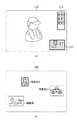
図2(a)にディスプレイ装置107に表示される画面の例として画面110を示す。
図2(b)中の200は、時分割で撮像センサ部101の全画素範囲で読み出し撮像されている画像であり、ディスプレイ装置107で表示されない移動体を検出する基となる画面である。この図2の画面110のように、ディスプレイ装置107で表示されているときに、ユーザーがハイライトになっていない他の移動体の項目を選択したとする。例えば、画面110において、表示再一覧リスト111と、画面上の位置を表したグラフィック描写112において、「動体0」を選択したとする。FIG. 2A shows a
2B is an image that is read and imaged in the entire pixel range of the
操作部106から指示を受けた描画表示処理部105は、選択した移動体の位置情報を含んだ検出情報を基にして撮像センサ部101で読み出す部分領域を設定し、制御を行なう。これにより、撮像センサ部101から対応する移動体の部分領域を読み出して撮像し、現像処理部102で現像処理、画像処理を行ない、描画表示処理部105に出力する。 Receiving the instruction from the
描画表示処理部105に入力された映像は該当する移動体の項目にハイライト表示のされた移動体のIDとともに、一覧リストとその画面上の位置を表したグラフィック描写を重畳してディスプレイ装置107に表示させる。前述した例では、ディスプレイ装置107に1つの移動体0をハイライト表示させる例であるが、もちろん、複数表示させることも可能である。 The video input to the drawing
図3(a)に、複数の移動体が選択されてディスプレイ装置107に表示されている画面の例を示す。図3(a)においては、被写体の移動体1および3に対して、撮像センサ部101で読み出す部分領域を設定されている移動体の映像であり、移動体のIDとともに一覧リストの項目にハイライト表示を行なっている。図3(b)においては、被写体の移動体1および3について、画面上の位置を表したグラフィック描写し、該当する移動体1、3についてハイライト表示を行なっている。 FIG. 3A shows an example of a screen on which a plurality of moving objects are selected and displayed on the
(第2の実施形態)
次に、本発明が適用される撮像システムで映像を外部に送信可能に構成した第2の実施形態を説明する。
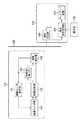
図4は、映像を外部に送信可能な撮像システムの構成例を示したブロック図である。
図4において、100は、撮像センサ部101で撮像した映像をネットワークの外部へ送信を行なう画像送信装置で、例えば、ネットワークカメラ本体などを表す。(Second Embodiment)
Next, a second embodiment in which an imaging system to which the present invention is applied is configured to be able to transmit an image to the outside will be described.
FIG. 4 is a block diagram illustrating a configuration example of an imaging system capable of transmitting video to the outside.
In FIG. 4,
120は画像送信装置100から送信された映像を受信し、表示を行なう映像受信端末である。撮像センサ部101からディスプレイ装置107までの構成要素は前述の撮像システムで示した機能と同じである。108は情報送信部であり、画像送信装置100で符号化された映像情報をビデオパケットにパケット化処理を行ない、LAN300に送信する。映像受信端末120には、情報受信部109が設けられており、LAN300から受信したビデオパケットをデパケット化し、符号化映像を構成させる。図4中の撮像センサ部101〜ディスプレイ装置107は、前述で示した構成と同じ機能を持つ構成であり、同じ構成については詳細な説明を省略する。
図4に示した構成で、映像受信端末120のディスプレイ装置107においても、図2および図3で示した画面のように表示される。もちろん、ユーザーがハイライトになっていない他の移動体の項目を選択した場合、選択した旨の通知を、LAN300を介して画像送信装置100の撮像センサ部101へ送られる。通知を受けた撮像センサ部101は読み出す部分領域を設定し、制御を行なう。 With the configuration shown in FIG. 4, the display is also displayed on the
これにより、撮像センサ部101から選択された移動体の部分領域を読み出し撮像して現像処理部102で現像処理、画像処理を行なって映像情報を作成し、作成した映像情報を、情報送信部108を介して映像受信端末120へ送られる。ディスプレイ装置107には、移動体のIDとともに一覧リストとその画面上の位置を表したグラフィック描写が重畳された映像が表示されることになる。 Thereby, the partial area of the moving body selected from the
以上の構成で、映像受信端末120の操作部106からの操作により、LAN300を介して前述と同様の動作を行なうことが可能となる。これら、画像送信装置100、映像受信端末120の数は、図4で示したように1個に限定されるものではなく、アドレスなどで識別できれば多数存在してもかまわない。 With the above configuration, the same operation as described above can be performed via the
LAN300に関しても、パケットデータを通すのに十分な帯域があるインターネットやイントラネットなどのネットワークであれば何でもよい。LAN300への物理的な接続形態として有線だけでなく無線の場合もありうるが、プロトコル的に接続されていれば、物理的な形態にこだわるものではない。 As for the
(その他の実施形態)
また、本発明は、以下の処理を実行することによっても実現される。即ち、前述した実施形態の機能を実現するソフトウェア(コンピュータプログラム)を、ネットワーク又は各種のコンピュータ読み取り可能な記憶媒体を介してシステム或いは装置に供給する。そして、そのシステム或いは装置のコンピュータ(またはCPUやMPU等)がプログラムを読み出して実行する処理である。(Other embodiments)
The present invention can also be realized by executing the following processing. That is, software (computer program) that implements the functions of the above-described embodiments is supplied to a system or apparatus via a network or various computer-readable storage media. Then, the computer (or CPU, MPU, etc.) of the system or apparatus reads out and executes the program.
101 撮像センサ部、102 現像処理部、103 撮像センサ制御部、104 移動体検出部、105 描画表示処理部、106 操作部、107 ディスプレイ装置DESCRIPTION OF
Claims (9)
Translated fromJapanese第2の時点において、前記移動体検出手段によって前記第1の数とは異なる第2の数の移動体が検出された場合、検出された移動体に対応する、前記第2の数の項目の一覧を前記表示手段に表示させ、
前記一覧から選択された項目に対応する、前記画像に含まれる一部の領域である部分領域の画像を前記表示手段に表示させる表示制御手段
を有することを特徴とする表示制御装置。When the firstnumber of moving bodies is detected by the moving body detecting means for detecting the moving bodies fromthe input imageat the first time point,the first number of items corresponding to the detected moving bodies Is displayed on the display means,
When a second number of moving bodies different from the first number is detected by the moving body detecting means at a second time point, the second number of items corresponding to the detected moving body Display the list on the display means,
Display controlapparatus characterized by havingthe corresponding to the selected itemfrom the list,the display control unit <br/> for displaying the image of the partial areawhich is a part of the region included in the image on the display unit .
ことを特徴とする請求項1記載の表示制御装置。The display control apparatus according to claim 1.
ことを特徴とする請求項1又は2に記載の表示制御装置。Wherein the display control unit, the moving body is detected, the display controldevice according an image indicating a positionon the image,to claim1 or 2, characterized in that to be displayed on the display unit as the list.
ことを特徴とする請求項1〜3のいずれか1項に記載の表示制御装置。Wherein the display control unit, the display controldevice accordingto any one of claims 1 to3, the image of the partial area corresponding to the item selected by the user, characterized in that to be displayed on the display means.
を有することを特徴とする請求項1〜4のいずれか1項に記載の表示制御装置。The display controlapparatus according to claim1 , further comprising an information transmission unit configured to transmit information indicating the list to the outside.
ことを特徴とする請求項1〜5のいずれか1項に記載の表示制御装置。The image display controldevice according to any one of claims 1 to5, characterized in that the video taken by the imaging means.
前記部分領域の画像は、前記第2の撮像モードで読み出された画像である
ことを特徴とする請求項6記載の表示制御装置。The imaging means may operate in a first imaging mode in which image data is read from all pixels of the imaging element that captures a subject, and a second imaging mode in which image data is read from some pixels of the imaging element. Is possible,
The display controlapparatus according to claim6 , wherein the image of the partial area is an image read in the second imaging mode.
前記移動体検出工程によって検出された移動体に対応する項目の一覧を表示手段に表示させる第1の表示制御工程と、
前記一覧から選択された項目に対応する、前記画像に含まれる一部の領域である部分領域の画像を前記表示手段に表示させる第2表示制御工程と
を有し、
前記第1の表示制御工程において、
第1の時点において前記移動体検出工程において第1の数の移動体が検出された場合、検出された移動体に対応する、前記第1の数の項目の一覧を前記表示手段に表示させ、
第2の時点において前記移動体検出工程において前記第1の数とは異なる第2の数の移動体が検出された場合、検出された移動体に対応する、前記第2の数の項目の一覧を前記表示手段に表示させる、
ことを特徴とする表示制御方法。A moving body detection step of detecting a moving body from aninput image;
Afirst display control step of causing a display means to displaya list of items corresponding to the mobile body detected by the mobile body detection step;
Asecond display control step for causingthe display means to display an imageof a partial area corresponding to an item selectedfrom the list,which is a partial area included in the image,
In the first display control step,
When a first number of moving bodies is detected in the moving body detecting step at a first time point, the display means displays a list of the first number of items corresponding to the detected moving bodies,
When a second number of moving objects different from the first number is detected in the moving object detection step at a second time point, the list of items of the second number corresponding to the detected moving objects Is displayed on the display means.
A display control method characterized by the above.
Priority Applications (2)
| Application Number | Priority Date | Filing Date | Title |
|---|---|---|---|
| JP2012196097AJP5955170B2 (en) | 2012-09-06 | 2012-09-06 | Display control apparatus, display control method, and program |
| US14/011,144US20140068514A1 (en) | 2012-09-06 | 2013-08-27 | Display controlling apparatus and display controlling method |
Applications Claiming Priority (1)
| Application Number | Priority Date | Filing Date | Title |
|---|---|---|---|
| JP2012196097AJP5955170B2 (en) | 2012-09-06 | 2012-09-06 | Display control apparatus, display control method, and program |
Publications (3)
| Publication Number | Publication Date |
|---|---|
| JP2014053722A JP2014053722A (en) | 2014-03-20 |
| JP2014053722A5 JP2014053722A5 (en) | 2015-10-01 |
| JP5955170B2true JP5955170B2 (en) | 2016-07-20 |
Family
ID=50189292
Family Applications (1)
| Application Number | Title | Priority Date | Filing Date |
|---|---|---|---|
| JP2012196097AActiveJP5955170B2 (en) | 2012-09-06 | 2012-09-06 | Display control apparatus, display control method, and program |
Country Status (2)
| Country | Link |
|---|---|
| US (1) | US20140068514A1 (en) |
| JP (1) | JP5955170B2 (en) |
Families Citing this family (6)
| Publication number | Priority date | Publication date | Assignee | Title |
|---|---|---|---|---|
| KR102302327B1 (en)* | 2014-12-08 | 2021-09-15 | 엘지전자 주식회사 | Terminal device, information display system and controlling method thereof |
| US11334228B1 (en)* | 2015-03-30 | 2022-05-17 | Evernote Corporation | Dynamic targeting of preferred objects in video stream of smartphone camera |
| WO2019058691A1 (en)* | 2017-09-20 | 2019-03-28 | 富士フイルム株式会社 | Imaging control device, imaging device, imaging control method, and imaging control program |
| TWI820194B (en) | 2018-08-31 | 2023-11-01 | 日商索尼半導體解決方案公司 | Electronic equipment and solid-state imaging devices |
| JP6635221B1 (en) | 2018-08-31 | 2020-01-22 | ソニー株式会社 | Imaging device, imaging system, imaging method, and imaging program |
| EP3803797B1 (en)* | 2018-09-03 | 2024-11-06 | Samsung Electronics Co., Ltd. | Methods and systems for performing editing operations on media |
Family Cites Families (8)
| Publication number | Priority date | Publication date | Assignee | Title |
|---|---|---|---|---|
| JP2004005511A (en)* | 2002-03-26 | 2004-01-08 | Toshiba Corp | Monitoring system, monitoring method and monitoring program |
| US20040146221A1 (en)* | 2003-01-23 | 2004-07-29 | Siegel Scott H. | Radiography Image Management System |
| JP2004336569A (en)* | 2003-05-09 | 2004-11-25 | Ntt Docomo Inc | Moving object monitoring system and moving object monitoring method |
| JP2006166400A (en)* | 2004-11-11 | 2006-06-22 | Matsushita Electric Ind Co Ltd | Imaging apparatus and imaging method |
| JP5371174B2 (en)* | 2005-09-12 | 2013-12-18 | キヤノン株式会社 | Image display device and image display method |
| JP4933354B2 (en)* | 2007-06-08 | 2012-05-16 | キヤノン株式会社 | Information processing apparatus and information processing method |
| JP2009069185A (en)* | 2007-09-10 | 2009-04-02 | Toshiba Corp | Video processing apparatus and video processing method |
| JP5567922B2 (en)* | 2010-07-21 | 2014-08-06 | キヤノン株式会社 | Image processing apparatus and control method thereof |
- 2012
- 2012-09-06JPJP2012196097Apatent/JP5955170B2/enactiveActive
- 2013
- 2013-08-27USUS14/011,144patent/US20140068514A1/ennot_activeAbandoned
Also Published As
| Publication number | Publication date |
|---|---|
| JP2014053722A (en) | 2014-03-20 |
| US20140068514A1 (en) | 2014-03-06 |
Similar Documents
| Publication | Publication Date | Title |
|---|---|---|
| JP5955170B2 (en) | Display control apparatus, display control method, and program | |
| JP5909147B2 (en) | IMAGING DEVICE, IMAGING DEVICE CONTROL METHOD, AND PROGRAM | |
| CN102572261A (en) | Method for processing an image and an image photographing apparatus applying the same | |
| US10991340B2 (en) | Image processing apparatus and image processing method | |
| JP2011097246A (en) | Image processing apparatus, method, and program | |
| JP2009021880A (en) | Remote imaging system | |
| US10778881B2 (en) | Video signal processing device, video signal processing method, and camera device | |
| US12348889B2 (en) | Image processing apparatus, method of controlling image processing apparatus, and program storage | |
| JP2023169254A (en) | Imaging element, operating method for the same, program, and imaging system | |
| JP7371076B2 (en) | Information processing device, information processing system, information processing method and program | |
| US9088699B2 (en) | Image communication method and apparatus which controls the output of a captured image | |
| JP2019032448A (en) | Control device, control method, and program | |
| US10943103B2 (en) | Human body detection apparatus, human body detection method, information processing apparatus, information processing method, and storage medium | |
| JP5954535B2 (en) | Image selection apparatus, image selection method, and program | |
| KR20130004123A (en) | Processing monitoring data in a monitoring system | |
| JP2013012930A (en) | Omnidirectional imaging device and control method therefor | |
| JP2015080048A (en) | Camera device, monitoring system, program used for them, and imaging method | |
| JP6354443B2 (en) | Control device, control system, control method, and program | |
| JP2014153517A (en) | Image processing device, image processing method, program, and storage medium | |
| JP5631181B2 (en) | Image processing apparatus, control method therefor, and program | |
| JP6917800B2 (en) | Image processing device and its control method and program | |
| JP2023110779A (en) | IMAGING DEVICE, INFORMATION PROCESSING DEVICE, CONTROL METHOD, PROGRAM AND STORAGE MEDIUM | |
| JP2016133908A (en) | Image generating apparatus and image generating method | |
| JP5605492B2 (en) | Image processing apparatus, image processing method, and image processing program | |
| JP6390245B2 (en) | Image storage device, image management method, and program |
Legal Events
| Date | Code | Title | Description |
|---|---|---|---|
| A521 | Request for written amendment filed | Free format text:JAPANESE INTERMEDIATE CODE: A523 Effective date:20150811 | |
| A621 | Written request for application examination | Free format text:JAPANESE INTERMEDIATE CODE: A621 Effective date:20150811 | |
| A131 | Notification of reasons for refusal | Free format text:JAPANESE INTERMEDIATE CODE: A131 Effective date:20160105 | |
| A521 | Request for written amendment filed | Free format text:JAPANESE INTERMEDIATE CODE: A523 Effective date:20160304 | |
| TRDD | Decision of grant or rejection written | ||
| A01 | Written decision to grant a patent or to grant a registration (utility model) | Free format text:JAPANESE INTERMEDIATE CODE: A01 Effective date:20160517 | |
| A61 | First payment of annual fees (during grant procedure) | Free format text:JAPANESE INTERMEDIATE CODE: A61 Effective date:20160614 | |
| R151 | Written notification of patent or utility model registration | Ref document number:5955170 Country of ref document:JP Free format text:JAPANESE INTERMEDIATE CODE: R151 |