JP5953441B2 - Biopsy system - Google Patents
Biopsy systemDownload PDFInfo
- Publication number
- JP5953441B2 JP5953441B2JP2015551078AJP2015551078AJP5953441B2JP 5953441 B2JP5953441 B2JP 5953441B2JP 2015551078 AJP2015551078 AJP 2015551078AJP 2015551078 AJP2015551078 AJP 2015551078AJP 5953441 B2JP5953441 B2JP 5953441B2
- Authority
- JP
- Japan
- Prior art keywords
- distal
- proximal
- sheath
- tube
- channel
- Prior art date
- Legal status (The legal status is an assumption and is not a legal conclusion. Google has not performed a legal analysis and makes no representation as to the accuracy of the status listed.)
- Active
Links
Images


Classifications
- A—HUMAN NECESSITIES
- A61—MEDICAL OR VETERINARY SCIENCE; HYGIENE
- A61B—DIAGNOSIS; SURGERY; IDENTIFICATION
- A61B10/00—Instruments for taking body samples for diagnostic purposes; Other methods or instruments for diagnosis, e.g. for vaccination diagnosis, sex determination or ovulation-period determination; Throat striking implements
- A61B10/02—Instruments for taking cell samples or for biopsy
- A61B10/04—Endoscopic instruments, e.g. catheter-type instruments
- A—HUMAN NECESSITIES
- A61—MEDICAL OR VETERINARY SCIENCE; HYGIENE
- A61B—DIAGNOSIS; SURGERY; IDENTIFICATION
- A61B1/00—Instruments for performing medical examinations of the interior of cavities or tubes of the body by visual or photographical inspection, e.g. endoscopes; Illuminating arrangements therefor
- A61B1/00064—Constructional details of the endoscope body
- A61B1/00071—Insertion part of the endoscope body
- A61B1/0008—Insertion part of the endoscope body characterised by distal tip features
- A61B1/00098—Deflecting means for inserted tools
- A—HUMAN NECESSITIES
- A61—MEDICAL OR VETERINARY SCIENCE; HYGIENE
- A61B—DIAGNOSIS; SURGERY; IDENTIFICATION
- A61B1/00—Instruments for performing medical examinations of the interior of cavities or tubes of the body by visual or photographical inspection, e.g. endoscopes; Illuminating arrangements therefor
- A61B1/00131—Accessories for endoscopes
- A61B1/00133—Drive units for endoscopic tools inserted through or with the endoscope
- A—HUMAN NECESSITIES
- A61—MEDICAL OR VETERINARY SCIENCE; HYGIENE
- A61B—DIAGNOSIS; SURGERY; IDENTIFICATION
- A61B1/00—Instruments for performing medical examinations of the interior of cavities or tubes of the body by visual or photographical inspection, e.g. endoscopes; Illuminating arrangements therefor
- A61B1/005—Flexible endoscopes
- A61B1/0051—Flexible endoscopes with controlled bending of insertion part
- A—HUMAN NECESSITIES
- A61—MEDICAL OR VETERINARY SCIENCE; HYGIENE
- A61B—DIAGNOSIS; SURGERY; IDENTIFICATION
- A61B1/00—Instruments for performing medical examinations of the interior of cavities or tubes of the body by visual or photographical inspection, e.g. endoscopes; Illuminating arrangements therefor
- A61B1/012—Instruments for performing medical examinations of the interior of cavities or tubes of the body by visual or photographical inspection, e.g. endoscopes; Illuminating arrangements therefor characterised by internal passages or accessories therefor
- A61B1/018—Instruments for performing medical examinations of the interior of cavities or tubes of the body by visual or photographical inspection, e.g. endoscopes; Illuminating arrangements therefor characterised by internal passages or accessories therefor for receiving instruments
- A—HUMAN NECESSITIES
- A61—MEDICAL OR VETERINARY SCIENCE; HYGIENE
- A61B—DIAGNOSIS; SURGERY; IDENTIFICATION
- A61B1/00—Instruments for performing medical examinations of the interior of cavities or tubes of the body by visual or photographical inspection, e.g. endoscopes; Illuminating arrangements therefor
- A61B1/04—Instruments for performing medical examinations of the interior of cavities or tubes of the body by visual or photographical inspection, e.g. endoscopes; Illuminating arrangements therefor combined with photographic or television appliances
- A—HUMAN NECESSITIES
- A61—MEDICAL OR VETERINARY SCIENCE; HYGIENE
- A61B—DIAGNOSIS; SURGERY; IDENTIFICATION
- A61B17/00—Surgical instruments, devices or methods
- A61B17/32—Surgical cutting instruments
- A61B17/320016—Endoscopic cutting instruments, e.g. arthroscopes, resectoscopes
- A—HUMAN NECESSITIES
- A61—MEDICAL OR VETERINARY SCIENCE; HYGIENE
- A61B—DIAGNOSIS; SURGERY; IDENTIFICATION
- A61B17/00—Surgical instruments, devices or methods
- A61B17/32—Surgical cutting instruments
- A61B17/3205—Excision instruments
- A61B17/32053—Punch like cutting instruments, e.g. using a cylindrical or oval knife
- A—HUMAN NECESSITIES
- A61—MEDICAL OR VETERINARY SCIENCE; HYGIENE
- A61B—DIAGNOSIS; SURGERY; IDENTIFICATION
- A61B8/00—Diagnosis using ultrasonic, sonic or infrasonic waves
- A61B8/08—Clinical applications
- A61B8/0833—Clinical applications involving detecting or locating foreign bodies or organic structures
- A61B8/0841—Clinical applications involving detecting or locating foreign bodies or organic structures for locating instruments
- A—HUMAN NECESSITIES
- A61—MEDICAL OR VETERINARY SCIENCE; HYGIENE
- A61B—DIAGNOSIS; SURGERY; IDENTIFICATION
- A61B8/00—Diagnosis using ultrasonic, sonic or infrasonic waves
- A61B8/12—Diagnosis using ultrasonic, sonic or infrasonic waves in body cavities or body tracts, e.g. by using catheters
- A—HUMAN NECESSITIES
- A61—MEDICAL OR VETERINARY SCIENCE; HYGIENE
- A61B—DIAGNOSIS; SURGERY; IDENTIFICATION
- A61B10/00—Instruments for taking body samples for diagnostic purposes; Other methods or instruments for diagnosis, e.g. for vaccination diagnosis, sex determination or ovulation-period determination; Throat striking implements
- A61B10/02—Instruments for taking cell samples or for biopsy
- A61B10/0233—Pointed or sharp biopsy instruments
- A61B10/0283—Pointed or sharp biopsy instruments with vacuum aspiration, e.g. caused by retractable plunger or by connected syringe
- A—HUMAN NECESSITIES
- A61—MEDICAL OR VETERINARY SCIENCE; HYGIENE
- A61B—DIAGNOSIS; SURGERY; IDENTIFICATION
- A61B17/00—Surgical instruments, devices or methods
- A61B17/34—Trocars; Puncturing needles
- A61B17/3403—Needle locating or guiding means
- A—HUMAN NECESSITIES
- A61—MEDICAL OR VETERINARY SCIENCE; HYGIENE
- A61B—DIAGNOSIS; SURGERY; IDENTIFICATION
- A61B17/00—Surgical instruments, devices or methods
- A61B17/34—Trocars; Puncturing needles
- A61B17/3478—Endoscopic needles, e.g. for infusion
- A—HUMAN NECESSITIES
- A61—MEDICAL OR VETERINARY SCIENCE; HYGIENE
- A61B—DIAGNOSIS; SURGERY; IDENTIFICATION
- A61B10/00—Instruments for taking body samples for diagnostic purposes; Other methods or instruments for diagnosis, e.g. for vaccination diagnosis, sex determination or ovulation-period determination; Throat striking implements
- A61B10/02—Instruments for taking cell samples or for biopsy
- A61B10/04—Endoscopic instruments, e.g. catheter-type instruments
- A61B2010/045—Needles
- A—HUMAN NECESSITIES
- A61—MEDICAL OR VETERINARY SCIENCE; HYGIENE
- A61B—DIAGNOSIS; SURGERY; IDENTIFICATION
- A61B17/00—Surgical instruments, devices or methods
- A61B17/32—Surgical cutting instruments
- A61B2017/320064—Surgical cutting instruments with tissue or sample retaining means
- A—HUMAN NECESSITIES
- A61—MEDICAL OR VETERINARY SCIENCE; HYGIENE
- A61B—DIAGNOSIS; SURGERY; IDENTIFICATION
- A61B17/00—Surgical instruments, devices or methods
- A61B17/34—Trocars; Puncturing needles
- A61B17/3403—Needle locating or guiding means
- A61B2017/3413—Needle locating or guiding means guided by ultrasound
- A—HUMAN NECESSITIES
- A61—MEDICAL OR VETERINARY SCIENCE; HYGIENE
- A61B—DIAGNOSIS; SURGERY; IDENTIFICATION
- A61B90/00—Instruments, implements or accessories specially adapted for surgery or diagnosis and not covered by any of the groups A61B1/00 - A61B50/00, e.g. for luxation treatment or for protecting wound edges
- A61B90/08—Accessories or related features not otherwise provided for
- A61B2090/0801—Prevention of accidental cutting or pricking
Landscapes
- Health & Medical Sciences (AREA)
- Life Sciences & Earth Sciences (AREA)
- Surgery (AREA)
- General Health & Medical Sciences (AREA)
- Public Health (AREA)
- Veterinary Medicine (AREA)
- Nuclear Medicine, Radiotherapy & Molecular Imaging (AREA)
- Animal Behavior & Ethology (AREA)
- Molecular Biology (AREA)
- Engineering & Computer Science (AREA)
- Biomedical Technology (AREA)
- Heart & Thoracic Surgery (AREA)
- Medical Informatics (AREA)
- Radiology & Medical Imaging (AREA)
- Pathology (AREA)
- Biophysics (AREA)
- Physics & Mathematics (AREA)
- Optics & Photonics (AREA)
- Orthopedic Medicine & Surgery (AREA)
- Ultra Sonic Daignosis Equipment (AREA)
- Endoscopes (AREA)
- Surgical Instruments (AREA)
Description
Translated fromJapanese 本発明は、生検システムに関する。
本願は、2014年6月10日に日本国に出願された特願2014−119922号に基づき優先権を主張し、その内容をここに援用する。The present invention relates to a biopsy system.
This application claims priority based on Japanese Patent Application No. 2014-119922 for which it applied to Japan on June 10, 2014, and uses the content here.
従来、微量の体組織を採取し、顕微鏡で観察する、生検といわれる検査方法が知られている。臓器等の深部の組織を採取する場合は、光学内視鏡による観察が困難であるため、超音波内視鏡等による臓器の超音波断層像を取得し、超音波観察下で臓器に生検針を刺入して組織を採取することがある。 Conventionally, an inspection method called biopsy, in which a small amount of body tissue is collected and observed with a microscope, is known. When collecting deep tissue such as organs, it is difficult to observe with an optical endoscope, so an ultrasonic tomographic image of the organ is obtained with an ultrasonic endoscope, etc., and a biopsy needle is taken into the organ under ultrasonic observation. The tissue may be collected by inserting the.
特許文献1には、このような用途に用いる生検用の処置具が記載されている。この処置具は、先端が鋭利に形成された管状の針管を備えており、針管を組織に刺入すると、針管の内部に組織の一部が進入する。針管を抜去することで、内部に進入した組織を採取することができる。
また、特許文献2には、可撓性案内管と、可撓性案内管が内部に挿通された可撓性補強管とを有する内視鏡用処置具が開示されている。この内視鏡用処置具では、可撓性案内管の折損を防止するように可撓性補強管が可撓性案内管を保護している。
生検システムにおける針管は、生検対象となる組織に向けて穿刺される。この針管は、湾曲動作可能な湾曲部を備えた軟性内視鏡における湾曲部の湾曲動作によって適切な穿刺位置へと案内される場合がある。 The needle tube in the biopsy system is punctured toward the tissue to be biopsied. The needle tube may be guided to an appropriate puncture position by a bending operation of the bending portion in a flexible endoscope having a bending portion capable of bending operation.
内視鏡とともに使用される針管は、組織に好適に穿刺されるように鋭利に形成された遠位端部分が内視鏡の内部を傷つけないようにする目的で、筒状の可撓性シースの内部に配されて穿刺対象となる組織まで内視鏡の内部を通って案内される。 A needle tube used with an endoscope has a cylindrical flexible sheath for the purpose of preventing a distal end portion sharply formed so as to be punctured suitably in a tissue from damaging the inside of the endoscope. Is guided through the interior of the endoscope to the tissue to be punctured.
内視鏡の内部を通じて穿刺対象となる部分まで案内される可撓性シースは、案内される過程で内視鏡から外力を受けて弾性変形する場合がある。このため、可撓性シースは、圧縮されたり伸長されたりすることによって針管との相対位置関係が変化する可能性を有している。 The flexible sheath guided to the portion to be punctured through the inside of the endoscope may be elastically deformed by receiving an external force from the endoscope during the guided process. For this reason, the flexible sheath has a possibility of changing a relative positional relationship with the needle tube by being compressed or extended.
針管と可撓性シースとの上記の相対位置関係の変化量を少なくするために、針管と同程度まで可撓性シースを硬く構成することも考えられる。しかしながら、この場合、内視鏡の上記の湾曲部内にこの硬い可撓性シースが配されたときに湾曲部が曲がりにくくなってしまう。 In order to reduce the amount of change in the relative positional relationship between the needle tube and the flexible sheath, it is also conceivable to make the flexible sheath as hard as the needle tube. However, in this case, the bending portion is difficult to bend when the rigid flexible sheath is disposed in the bending portion of the endoscope.
本発明は、上述した事情に鑑みてなされたものであって、その目的は、可撓性シースが全体として伸縮しにくく、且つ内視鏡の湾曲部の湾曲性能を低下させにくい生検システムを提供することである。 The present invention has been made in view of the above-described circumstances, and an object thereof is a biopsy system in which a flexible sheath is difficult to expand and contract as a whole and the bending performance of a bending portion of an endoscope is difficult to be lowered. Is to provide.
本発明の第一の態様によれば、生検システムは、チャンネルを有し体内に挿入される挿入部と、前記挿入部の一部に配され前記チャンネルの一部を能動的に湾曲変形させる能動湾曲部と、を備えた内視鏡と、前記チャンネル内に挿通可能な内視鏡用処置具と、を備える。前記内視鏡用処置具は、前記チャンネル内に挿通可能であり可撓性を有する筒状のシースと、生検のために組織に穿刺可能な鋭利な端部を有し前記シースの内部に配された針管と、前記針管の近位端に接続された針スライダと、前記シースの近位端に接続された操作本体と、を有し、前記針スライダが前記操作本体に対して移動することで、前記シースの内部で前記針管を移動させ、前記針管を前記シースの遠位端から突没させる操作部と、を有する。前記シースは、前記シースの遠位端を含む前記シースの遠位部分に配された遠位筒部と、前記遠位筒部の近位端に固定され前記遠位筒部と同軸をなし前記遠位筒部よりも可撓性が低い近位筒部と、前記遠位筒部と前記近位筒部とを接続する接続部と、を有する。前記遠位筒部と前記近位筒部との境界部位は、前記シースの遠位端が前記チャンネルの遠位端から突出して前記内視鏡により光学的に観察可能である位置関係において前記能動湾曲部の近位端よりも近位側に位置している。According to the first aspect of the present invention, the biopsy system has an insertion part having a channel and inserted into the body, and is disposed in a part of the insertion part and actively curves and deforms a part of the channel. An endoscope including an active bending portion, and an endoscope treatment tool that can be inserted into the channel. The endoscopic treatment instrument has a flexible cylindrical sheath that can be inserted into the channel, and a sharp end that can puncture tissue for biopsy. Anda needle slider connected to the proximal end of the needle tube, and an operation body connected to the proximal end of the sheath, and the needle slider moves relative to the operation body. Thus, the operation unit moves the needle tube inside the sheath and causesthe needle tube to protrude and retract from the distal end of the sheath . The sheath includes a distal tube portion disposed at a distal portion of the sheath including a distal end of the sheath, and is fixed to a proximal end of the distal tube portion and is coaxial with the distal tube portion. A proximal tube portion having lower flexibility than the distal tube portion; and a connecting portion that connects the distal tube portion and the proximal tube portion. The boundary portion between the distal tube portion and the proximal tube portion is active in a positional relationship in which the distal end of the sheath projects from the distal end of the channel and can be optically observed by the endoscope. It is located closer to the proximal side than the proximal end of the curved portion.
本発明の第二の態様によれば、前記第一の態様に係る生検システムにおいて、前記接続部は、前記遠位筒部の近位端と前記近位筒部の遠位端とがともに内部に配された筒状部材であってもよい。前記遠位筒部は、前記接続部に固定された可撓性のコイルと、前記コイルの外周面を覆うように前記コイルに取り付けられた被覆と、を有していてもよい。前記被覆の外径と前記接続部の外径との差は前記近位筒部の外径と前記接続部の外径との差よりも小さくてもよい。 According to the second aspect of the present invention, in the biopsy system according to the first aspect, the connection portion includes both a proximal end of the distal tube portion and a distal end of the proximal tube portion. It may be a cylindrical member arranged inside. The distal cylinder part may have a flexible coil fixed to the connection part, and a coating attached to the coil so as to cover an outer peripheral surface of the coil. The difference between the outer diameter of the covering and the outer diameter of the connecting portion may be smaller than the difference between the outer diameter of the proximal cylindrical portion and the outer diameter of the connecting portion.
本発明の第三の態様によれば、前記第二の態様に係る生検システムにおいて、前記遠位筒部の中心線方向における単位長さあたりの前記遠位筒部の自重による弾性変形量は、前記近位筒部の中心線方向における単位長さあたりの前記遠位筒部の自重による弾性変形量よりも大きくてもよい。 According to the third aspect of the present invention, in the biopsy system according to the second aspect, the amount of elastic deformation due to the weight of the distal cylinder part per unit length in the center line direction of the distal cylinder part is The amount of elastic deformation due to the weight of the distal cylinder per unit length in the center line direction of the proximal cylinder may be larger.
本発明の第四の態様によれば、前記第三の態様に係る生検システムにおいて、前記被覆の外周面は前記コイルの外周面に倣って凹凸形状を有していてもよい。 According to the fourth aspect of the present invention, in the biopsy system according to the third aspect, the outer peripheral surface of the coating may have an uneven shape following the outer peripheral surface of the coil.
本発明の第五の態様によれば、前記第四の態様に係る生検システムにおいて、前記内視鏡は、前記内視鏡用処置具及び生検対象部位を撮像可能な撮像部と、前記撮像部よりも遠位側に配された超音波走査機構と、を有していてもよい。前記チャンネルは、前記シースを前記超音波走査機構の走査範囲に向けて屈曲させるように前記挿入部の中心線に対して傾斜されたスロープ部と、前記挿入部の中心線と平行なチャンネルチューブと、前記スロープ部と前記チャンネルチューブを繋ぐアングル部と、を有していてもよい。前記シースの遠位端が前記チャンネルの前記遠位端から突出して前記内視鏡により光学的に観察可能である前記位置関係において、前記針管の前記端部は前記操作部によって近位側に限界まで移動されたときに、前記能動湾曲部よりも遠位側且つ前記スロープ部より近位側に位置していてもよい。 According to a fifth aspect of the present invention, in the biopsy system according to the fourth aspect, the endoscope includes an imaging unit capable of imaging the endoscopic treatment tool and a biopsy target site; And an ultrasonic scanning mechanism disposed on the distal side of the imaging unit. The channel includes a slope portion inclined with respect to a center line of the insertion portion so as to bend the sheath toward a scanning range of the ultrasonic scanning mechanism, and a channel tube parallel to the center line of the insertion portion. And an angle portion connecting the slope portion and the channel tube. In the positional relationship where the distal end of the sheath protrudes from the distal end of the channel and can be optically observed by the endoscope, the end of the needle tube is limited to the proximal side by the operating portion. When moved to the position, it may be located distal to the active bending portion and proximal to the slope portion.
本発明によれば、可撓性シースが全体として伸縮しにくく、且つ内視鏡の湾曲部の湾曲性能を低下させにくい生検システムを提供することができる。 According to the present invention, it is possible to provide a biopsy system in which the flexible sheath is less likely to expand and contract as a whole and the bending performance of the bending portion of the endoscope is unlikely to deteriorate.
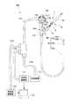
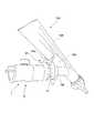
本発明の一実施形態について説明する。図1は、処置具1および超音波内視鏡100を備えた本実施形態の生検システム150の概略構成を示す図である。図2は、生検システム150の内視鏡である超音波内視鏡100の先端部分の断面図である。 An embodiment of the present invention will be described. FIG. 1 is a diagram illustrating a schematic configuration of a
本実施形態の生検システム150は、体内の組織を採取する生検に利用可能な医療機器である。生検システム150は、超音波内視鏡100と、内視鏡用処置具1(以下、単に「処置具」と称する)とを備える。 The
図1に示すように、超音波内視鏡100は、先端から体内に挿入される挿入部101と、挿入部101の基端に取り付けられた操作部109と、操作部109の側部に一端が接続されたユニバーサルコード112と、ユニバーサルコード112の他端に分岐ケーブル112aを介して接続された光源装置113と、ユニバーサルコード112の他端に分岐ケーブル112bを介して接続された光学的観察部114と、ユニバーサルコード112の他端に分岐ケーブル112cを介して接続された超音波観察部115とを備える。 As shown in FIG. 1, the
挿入部101は、先端硬質部102、湾曲部105、および可撓管部106が先端側からこの順に並べて設けられている。 The
先端硬質部102は、光学的観察を行うための光学撮像機構(撮像部)103と、超音波観察を行うための超音波走査機構104とを備える。 The distal end
光学撮像機構103は、先端硬質部102の斜め前方に視野が向けられた撮像光学系と、撮像光学系を通じて入射した被写体の像を検出するCCDやCMOSなどのイメージセンサと、イメージセンサの動作を制御するCPU等の不図示の各種構成を備える。 The
超音波走査機構(プローブ)104は、超音波を出射し、受信する図示しない超音波振動子を備える。超音波走査機構104は、超音波振動子が発した超音波が観察対象に当たって反射した反射波を超音波振動子によって受信し、超音波振動子が受信した超音波に基づいた信号を超音波観察部115へ出力する。本実施形態の超音波走査機構104は、生検対象となる組織の超音波画像を取得し、また、生検の手技の過程で針管3の超音波画像を取得するために使用される。 The ultrasonic scanning mechanism (probe) 104 includes an ultrasonic transducer (not shown) that emits and receives ultrasonic waves. The
湾曲部105は、筒状に形成されており、湾曲部105の先端105a(図4参照)に固定され操作部109まで延びる図示しないアングルワイヤを操作部109において牽引操作することによって、所定の方向へ湾曲する能動湾曲部である。本実施形態の湾曲部105は、超音波の走査方向に沿って2方向に湾曲可能である。 The bending
本実施形態では、例えば呼吸器の治療のために、挿入部の外径が細く2方向に湾曲可能な内視鏡を用いている。例えば消化器の処置を行う場合等には、外径は太いが操作自由度の高い4方向に湾曲可能な内視鏡を用いてもよい。 In the present embodiment, for example, an endoscope that has a thin outer diameter and can be bent in two directions is used for respiratory treatment. For example, when performing a digestive organ treatment, an endoscope that can be bent in four directions with a large outer diameter but a high degree of freedom of operation may be used.
可撓管部106は、管腔組織内や体腔内において先端硬質部102を所望の位置に案内できるように柔軟に形成された筒状部材である。湾曲部105と可撓管部106とのそれぞれの内部には、チャンネル107と、送気送水や吸引などを行うための図示しない管路とが設けられている。 The
図1及び図2に示すチャンネル107は、処置具1を挿通するための筒状部である。チャンネル107の一端は先端硬質部102の先端部近傍に開口され、チャンネル107の他端は操作部109の先端側の側面に開口されている。チャンネル107の他端には、フランジ状に形成された基端口金108が固定されている。基端口金108には、超音波内視鏡100とともに使用される処置具1を固定することができる。 The
チャンネル107は、図2に示すように、先端硬質部102内において挿入部101の軸線C1に対して傾斜したスロープ部107aと、スロープ部107aの基端に接続されたアングルチューブ107b(アングル部)と、アングルチューブ107bの基端に接続されたチャンネルチューブ107cとを有する。 As shown in FIG. 2, the
スロープ部107aは、挿入部101の軸線C1に対して傾斜する直線を中心線とする貫通孔が先端硬質部102に形成されていることによって先端硬質部102に設けられている。スロープ部107aに形成された貫通孔の中心線C2は、超音波走査機構104の走査面に含まれる位置にある。このため、スロープ部107aに処置具1が挿通されたときに、スロープ部107aは、処置具1の針管3を上述の走査面へと案内可能である。挿入部101の軸線C1に対するスロープ部107aの中心線C2の傾斜角度は、処置対象となる部位等に対応して適宜設定されてよい。本実施形態では、スロープ部107aの中心線C2は、挿入部101の軸線C1に対して、たとえば26度の角度をなして傾斜している。 The
アングルチューブ107bは、チャンネルチューブ107cからスロープ部107aへと案内される処置具1の先端の向きをスロープ部107aの中心線C2に沿う方向へと変化させるために所定の角度を有して屈曲あるいは湾曲した形状のチューブである。アングルチューブ107bは、スロープ部107aとチャンネルチューブ107cとを繋ぐ。本実施形態では、アングルチューブ107bは、一定の曲率で曲げられた弧状である。 The
チャンネルチューブ107cは、先端硬質部102の基端近傍において、挿入部101の軸線C1方向と平行な方向で挿入部101の先端側に向けて開口されており、挿入部101の軸線C1と略平行に挿入部101の基端側に延びて基端口金108に固定されている。 The
図1に示す操作部109は、超音波内視鏡100を使用する術者が手に持つことができるように形成された外面を有する。操作部109は、アングルワイヤを牽引して湾曲部105を湾曲動作させるための湾曲操作機構110と、管路を通じて送気、送水、あるいは吸引をするための複数のスイッチ111とを備えている。 The
光源装置113は、光学撮像機構103によって撮像するための照明光を発するための装置である。 The
光学的観察部114は、光学撮像機構103のイメージセンサによって撮像された映像をモニター116に映し出すように構成されている。 The
超音波観察部115は、超音波走査機構104から出力された信号を受信し、この信号に基づいて画像を生成してモニター116に映し出すように構成されている。 The
次に、処置具1の構成について説明する。図3は、処置具1の先端部分の断面図である。図4は、処置具1が超音波内視鏡100に取り付けられた状態を示す断面図である。図5は、処置具1を示す部分断面図である。図6は、処置具1の操作部8を示す図である。 Next, the configuration of the
図1及び図3に示すように、処置具1は、体内に挿入される挿入体2と、挿入体2を操作するための操作部(処置具操作部)8と、スタイレット(芯金)27とを備える。 As shown in FIGS. 1 and 3, the
挿入体2は、超音波内視鏡100の挿入部101の先端から突出可能にチャンネル107に取り付け可能な長尺部材である。挿入体2は、針管3と、針管3が内部に挿通された筒状のシース7とを備える。 The
針管3は、先端と基端とを有し、操作部8により進退操作される筒状部材である。針管3の材質としては、可撓性を有しているとともに、外力により曲げられても容易に直線状態に復元する弾性を有する材質であることが好ましい。たとえば、針管3の材料としては、ステンレス合金、ニッケルチタン合金、コバルトクロム合金などの合金材料を採用することができる。 The
針管3の先端には、組織に針管3を穿刺するために鋭利に形成されているとともに針管3の内部の組織を吸引するための開口31が形成されている。針管3の先端に設けられた開口31は、針管を形成する管状部材の先端を自身の軸線X1に対して斜めに切り落とすことにより形成されており、生体組織に刺入できるように鋭利に形成されている。開口31の具体的形状は、対象とする組織等を考慮して公知の各種形状から適宜選択されてよい。 At the distal end of the
図3に示すように、シース7は、遠位筒部71と、近位筒部72と、接続部73と、被覆部(被覆)74とを有する。 As shown in FIG. 3, the
遠位筒部71は、可撓性を有する管状部材からなる。遠位筒部71は、たとえば金属等からなる素線がコイル状に巻かれて筒状に形成されている。遠位筒部71を構成する素線は、遠位筒部71の曲がりやすさや復元力に着目して適切に選択される。例えば、遠位筒部71を構成する素線の材質としては、形状記憶合金や超弾性合金等を採用することができる。遠位筒部71を構成する素線の形状としては、断面円形や断面矩形等を採用することができる。遠位筒部71の先端71aは、被覆部74の内部に僅かに入り込んだ位置にある。遠位筒部71の基端71bは、接続部73に固定されている。 The
近位筒部72は、操作部8の先端から延出している。近位筒部72は、可撓性を有する管状部材からなる。近位筒部72は、遠位筒部71よりも可撓性が低い。言い換えると、近位筒部72は、遠位筒部71よりも剛性が高い。近位筒部72は、たとえば金属等からなる素線がコイル状に巻かれて筒状に形成されている。近位筒部72を構成する素線は、近位筒部72の曲がりやすさや復元力に着目して適切に選択される。例えば、近位筒部72を構成する素線の材質としては、形状記憶合金や超弾性合金等を採用することができる。近位筒部72を構成する素線の形状としては、断面円形や断面矩形等を採用することができる。近位筒部72の先端72aは、接続部73に固定されている。近位筒部72の基端は、操作部8に固定されている。 The
遠位筒部71と近位筒部72との各々の曲がりやすさ及び復元力について説明する。遠位筒部71は、遠位筒部71の一部を固定して中心線を略水平に保持した時に遠位筒部71の自重によって中心線が湾曲する程度のバネ性の部材である。具体的には、遠位筒部71は、中心線方向の長さが所定の基準長(300mm)である場合に中心線方向の一端を水平に固定したときの他端の弾性変形量(垂下量)が100mm以内となる弾性を有する。 The bendability and restoring force of each of the
また、遠位筒部71の硬さは、処置具1が超音波内視鏡100に取り付けられた状態で超音波内視鏡100の湾曲部105の可動域の全域に亘って湾曲部105が湾曲動作可能となることを考慮して設定されてもよい。この場合の硬さの設定は、針管3の硬さも考慮して設定される。なお、超音波内視鏡100の湾曲部105がその可動域の全域に亘って常に湾曲動作可能となることは必須ではない。 Further, the hardness of the distal
近位筒部72は、近位筒部72の一部を固定して中心線を略水平に保持した時に近位筒部72の自重によって中心線が湾曲する程度のバネ性の部材である。具体的には、近位筒部72は、中心線方向の長さが所定の基準長(300mm)である場合に中心線方向の一端を水平に固定したときの他端の弾性変形量(垂下量)が50mm以内となる弾性を有する。 The
また、遠位筒部71と近位筒部72との各々における単位長さあたりの自重による垂れ下がり量(以下、「垂下率」という。)の関係について、遠位筒部71の垂下率は近位筒部72の垂下率よりも高い。一例を挙げると、遠位筒部71における垂下率が0.333(上記基準長さにおいて垂下量が100mm)で、近位筒部72における垂下率が0.167(上記基準長さにおいて垂下量が50mm)である。遠位筒部71の垂下率は、近位筒部72の垂下率の1.5倍以上2.5倍以下の範囲にあると好ましい。 Further, regarding the relationship of the amount of sag due to its own weight per unit length in each of the
接続部73は、遠位筒部71と近位筒部72とを接続するための部材である。本実施形態の接続部73は、遠位筒部71の基端71bが挿入される開口と近位筒部72の先端72aが挿入される開口とを有する筒状部材である。接続部73の中心線は、遠位筒部71及び近位筒部72の中心線と同軸上である。 The
接続部73の中心線方向における接続部73の長さが短い方がシース7における硬質部分の長さを短くすることができるので好ましい。また、接続部73の中心線方向における接続部73の長さが長いと、遠位筒部71や近位筒部72に対する固定領域を多く確保できるので遠位筒部71と近位筒部72との固定が確実となる。接続部73の中心線方向における接続部73の長さは、シース7に求める柔軟性と、遠位筒部71と近位筒部72との接続強度とを好適に両立させることを考慮して設定される。 It is preferable that the length of the connecting
被覆部74は、遠位筒部71の外周面の全域に亘って遠位筒部71を被覆する樹脂部材である。被覆部74は、遠位筒部71を構成する素線がコイル状に成形されたあとにこのコイル状の遠位筒部71に被せて密着されるたとえば熱収縮チューブによって構成されている。 The covering
被覆部74は、接続部73の径方向における接続部73の外壁部分の厚さと同じあるいはそれ以下の厚みの樹脂により構成されたチューブによって形成されている。このため、遠位筒部71の外周面に被覆部74が被覆された状態における被覆部74の外径は、接続部73の外径と略同等あるいは接続部73の外径よりも小さい。被覆部74の材質は、シース7の可撓性に対する影響が少ない材質であることが好ましい。また、被覆部74は、シース7における遠位筒部71の湾曲変形に倣って柔軟に伸縮可能であることが好ましい。 The covering
被覆部74の内面は、遠位筒部71を構成する素線の外面形状に倣った形状になっている。本実施形態では、被覆部74の内面は、遠位筒部71を構成する素線がコイル状に巻かれたことで隣接している部分の隙間に入り込んではいない。 The inner surface of the covering
また、被覆部74の内面は、遠位筒部71に対して固定されていない。すなわち、被覆部74は、被覆部74自身が遠位筒部71の外径よりも小さくなろうとする収縮力によって遠位筒部71の外面に係合している。したがって、被覆部74の内面の一部は、遠位筒部71が湾曲変形されたときに、遠位筒部71を構成する素線の外面から離間して伸縮可能である。 Further, the inner surface of the covering
被覆部74の外面は、遠位筒部71を構成する素線の外面形状に対応した凹凸形状を有している。なお、被覆部74の外面形状は特に限定されない。 The outer surface of the covering
操作部8は、図5及び図6に示すように、操作本体9と、操作本体9の先端側に設けられたシースアジャスター18と、操作本体9の基端側に設けられた針スライダ23とを備える。 As shown in FIGS. 5 and 6, the
操作本体9は、例えばABS樹脂等で形成されている。操作本体9は、針管3およびシース7が挿通可能な管腔を有する。操作本体9の先端側は、管状に形成されたシースアジャスター18に挿入されている。操作本体9の基端側は、管状に形成された針スライダ23に挿入されている。操作本体9とシースアジャスター18、および操作本体9と針スライダ23は、外周面に形成された図示しない溝あるいは凸部等が互いに係合することにより、軸線まわりの相対回転が抑制されつつ軸線方向に摺動可能である。 The operation body 9 is made of, for example, ABS resin. The operation body 9 has a lumen through which the
シースアジャスター18の先端部には、超音波内視鏡100の基端口金108に着脱可能なスライドロック51が設けられている。スライドロック51を操作部8の軸線に直交する方向にスライドして基端口金108と係合させることで、操作部8を超音波内視鏡100に固定することができる。スライドロック51の先端側には、一対の壁部52a、52bを有するホルダ(固定部)52が設けられている。ホルダ52は、シースアジャスター18に対して固定されている。ホルダ52の一対の壁部52a、52bは、略平行に配置されており、その距離は、超音波内視鏡100の操作部109の先端側がガタつかずに収まる程度の値に設定されている。 At the distal end of the
シースアジャスター18の先端部からは、例えばステンレス製の支持パイプ53が突出している。支持パイプ53の先端部は、処置具1を超音波内視鏡100に取り付ける際に、チャンネル107内に挿入される。支持パイプ53は操作本体9内に挿入されている。支持パイプ53の基端は、針スライダ23が操作本体9に対して最も前進された状態において、針スライダ23の先端よりも基端側(例えば図6に示す位置P1)に位置している。シース7は支持パイプ53内に挿通されており、基端部が支持パイプ53の基端から突出して接着等により操作本体9に固定されている。 For example, a
シースアジャスター18には、固定ネジ54が取り付けられている。固定ネジ54は、シースアジャスター18を貫通して操作本体9に設けられた図示しないネジ穴に嵌合している。固定ネジ54を操作本体9に対して締め込むと、シースアジャスター18が操作本体9に押し当てられてシースアジャスター18と操作本体9とを摺動不能に固定することができる。シースアジャスター18と操作本体9との位置関係を変化させることで、操作部8を超音波内視鏡100に固定した際の、チャンネル107からのシース7の突出長を調節することができ、固定ネジ54によりこの突出長を固定することができる。 A fixing
図1に示すように、固定ネジ54の軸線は、ホルダ52に収まった操作部109の軸線に向かうように配置されるのが好ましい。これにより、操作部8を正面に位置させたときに固定ネジ54が左右に偏らないため、術者の利き手によらず容易に操作することができる。固定ネジ54の軸線がホルダ52に収まった操作部109の軸線に向かっていれば、固定ネジ54が図1と反対側に向いて取り付けられていても、概ね同様の効果を得ることができる。 As shown in FIG. 1, the axis of the fixing
シースアジャスター18の先端部の外周面には、術者が把持しやすいように凹凸が設けられている。 The outer peripheral surface of the distal end portion of the
針スライダ23は、針管3の基端に固定されている。また、針スライダ23は、操作本体9に対して移動可能となるように操作本体9に連結されている。針管3の基端側は、シース7の基端から突出して針スライダ23に固定されているため、針スライダ23を操作本体9に対して摺動することで、シース7の先端から針管3を突没させることができる。針スライダ23の先端側において、ストッパ61が操作本体9に対して移動可能に取り付けられている。ストッパ61は固定ネジ62を有し、固定ネジ62を締め込むことで、操作本体9に対して固定することができる。図1に示すように、固定ネジ62の軸線は、ホルダ52に収まった操作部109の軸線に向かうように配置されるのが好ましい。これにより、操作部8を正面に位置させたときに固定ネジ62が左右に偏らないため、術者の利き手によらず容易に操作することができる。固定ネジ62の軸線がホルダ52に収まった操作部109の軸線に向かっていれば、固定ネジ62が図1と反対側に向いて取り付けられていても、概ね同様の効果を得ることができる。 The
固定ネジ62は、上述の固定ネジ54と同じ方向に向けられていてもよいし、互いに逆方向に向けられていてもよい。 The fixing
図5に示すように、針スライダ23は、ストッパ61と接触する位置までしか操作本体9に対して前進できないので、操作本体9に対するストッパ61の固定位置を調節することで、針管3のシース7からの最大突出長を調節することができる。本実施形態では、針スライダ23による針管3の操作ストローク長L2は少なくとも40mmある。 As shown in FIG. 5, the
操作本体9の基端側に針スライダ23が限界まで移動した位置に針スライダ23がある状態が、処置具1の使用開始前における初期状態である。初期状態では、針管3の先端はシース7内にある。より具体的には、初期状態では、針管3の先端は遠位筒部71内にある。また、シース7が超音波内視鏡100のチャンネル107に取り付けられてシース7の先端部分が超音波内視鏡100によって光学的に観察可能である位置関係では、針管3の先端は、湾曲部105の先端105aよりも先端側に位置している。 The state in which the
本実施形態では、初期状態において、湾曲部105の先端105aから基端105bに至るまでの全域において、針管3、遠位筒部71、及び被覆部74がチャンネルチューブ107c内に配されている。このため、湾曲部105の全域におけるチャンネルチューブ107cの内容物は一様な硬さであり、湾曲部105の湾曲性能を部分的に変動させるような硬さの差が生じていない。 In the present embodiment, in the initial state, the
初期状態におけるシース7に対する針管3の先端の位置は、シース7の伸びあるいは縮みと、針管3の伸びあるいは縮みとの影響により変動する。シース7に対する針管3の先端の位置の変動は、温度、湿度、超音波内視鏡100のチャンネル107に対する取り付け状態、及び処置具1にかかる操作力量等の影響を受ける。 The position of the tip of the
たとえば、遠位筒部71と針管3とが互いに異なる材料で形成されている場合は、温度変化に対応した膨張率が遠位筒部71と針管3とで互いに異なるので、操作本体9の基端側に針スライダ23が限界まで移動した位置に針スライダ23がある初期状態であっても、温度に応じてシース7に対する針管3の位置は異なる。 For example, when the distal
また、チャンネル107に挿入体2を挿入する過程(図4参照)で近位筒部72はその中心線方向の圧縮力を受けて針管3の中心線に対して蛇行することがあり、この場合には、チャンネル107の先端まで挿入体2の先端が案内された状態において、チャンネル107に挿入体2が挿入されていない状態と比較してシース7の先端に近い位置に針管3の先端が位置している。 Further, in the process of inserting the
本実施形態では、温度、湿度、超音波内視鏡100のチャンネル107に対する取り付け状態、及び処置具1にかかる操作力量を考慮して、処置具1を用いた手技として想定される環境において初期状態では図5に示すように針管3の先端が常に遠位筒部71内にあるように設定されている。 In the present embodiment, considering the temperature, humidity, the state of attachment of the
操作本体9に対する針スライダ23の移動量は、シース7に対する針管3の先端の移動量に略対応する(図5参照)。すなわち、針スライダ23が針管3をシース7に対して移動させることで、シース7に対する針管3の先端の移動量(相対ストローク長L1)は、針スライダ23の実際の移動量(操作ストローク長L2)に針管3の伸びあるいは縮みを加味した分となる。針管3の伸びあるいは縮みは、針管3自身の伸縮性(弾性)、針管3とシース7との間の摩擦抵抗の大きさ、チャンネル107内におけるシース7の蛇行状態、及びシース7内における針管3の蛇行状態の影響を受ける。 The amount of movement of the
操作本体9の先端側に針スライダ23が限界まで移動した位置に針スライダ23があるときに、針管3の先端はシース7の先端から突出されている。操作本体9の先端側に針スライダ23が限界まで移動した位置に針スライダ23があるときの針管3の突出長は、針スライダ23の操作ストローク長L2よりは短くなるが、少なくとも40mmあることが好ましい。 When the
針スライダ23の基端部には開口23aが設けられており、スタイレット27を針管3の基端から針管3内に挿入することができる。開口23aにはネジ山が設けられており、公知のシリンジ等を開口23aに接続可能である。針スライダ23の先端部の外周面には、術者が把持しやすいように凹凸が設けられている。 An
図3及び図5に示すスタイレット27は、針スライダ23の開口23aに取り付け可能なツマミ27aと、ツマミ27aに固定された芯27bとを有する。芯27bは、針管3の内面形状に対応した断面形状を有している。本実施形態では芯27bは断面円形である。 The
以上の構成を有する生検システム150の使用時の動作について説明する。図7は、処置具1と超音波内視鏡100との取り付け状態を示す斜視図である。図8から図10は、生検システム150の作用を示す説明図である。以下では、肺の深部に位置する病変を対象組織として処置具1の針管3を刺入し、針管3の内部を通じて病変の細胞などを回収する生検の処置を例に説明する。 An operation when the
まず術者は、図1に示す超音波内視鏡100の挿入部101を体内に挿入し、光学撮像機構103で観察しながら、適宜湾曲部105を湾曲させつつ対象組織の付近まで挿入部101の先端部を導入する。導入後、術者は、光学撮像機構103および超音波走査機構104による観察結果に基づいて、生検を行う部位を決定する。 First, the operator inserts the
次に、術者は、超音波内視鏡100の操作部109に設けられた基端口金108からチャンネル107の内部へ、処置具1の挿入体2を先端側から挿入する。さらに、術者は、図7に示すように操作部109の先端側をホルダ52の一対の壁部52a、52b間に進入させてから、処置具1の操作部8に設けられたスライドロック51を基端口金108に係合させる。これにより、処置具1の操作部8は、操作部109に対して回転しないように超音波内視鏡100に固定される。 Next, the surgeon inserts the
このとき、処置具1は、上述の初期状態にあり、すなわち、針管3の先端は遠位筒部71内にある。遠位筒部71には被覆部74が密着しているので、遠位筒部71を構成する素線は概ね密着巻き状態で保持される。遠位筒部71がチャンネル107の湾曲形状に倣って変形されると、遠位筒部71を構成する素線の一部は互いに離間し、被覆部74は遠位筒部71の湾曲変形に倣って引き延ばされる。遠位筒部71の素線間隔のばらつきは、遠位筒部71の素線に被覆部74が密着していることによって少なく抑えられている。 At this time, the
湾曲した可撓管部106に沿ってチャンネル107内を案内される針管3は、針管3の先端が遠位筒部71を突き破らないように保護されている。また、チャンネル107の内面と挿入体2の最外面との間の摩擦抵抗によって、チャンネル107内への挿入体2の押し込みに従ってシース7には圧縮による縮みや蛇行が蓄積されてゆくことがある。この場合、シース7の先端が針管3に対して相対的に基端側に移動することとなるが、この場合にも針管3の先端は遠位筒部71にあり保護されている。 The
次に、術者は、固定ネジ54を緩め、光学撮像機構103および超音波走査機構104によってシース7および体内を観察しながら、図8に示すように、シースアジャスター18と操作本体9とを相対的に摺動させて、超音波内視鏡100の挿入部101の先端からのシース7の突出量を適切な量に調整する。調整後、術者は固定ネジ54を締め込んでこの突出量を固定する。 Next, the operator loosens the fixing
シース7の突出量の調整がなされた後も、針管3の先端は、遠位筒部71内にある。また、針管3の先端は、チャンネル107において、湾曲部105とアングルチューブ107bとの間、アングルチューブ107b内、あるいはスロープ部107a内のいずれかの位置にある。 Even after the amount of protrusion of the
シース7における接続部73の位置は、超音波内視鏡100の湾曲部105の基端105bよりもさらに基端側にある。具体的には、超音波内視鏡100を用いてシース7の先端を光学的に観察可能であるときに、接続部73は湾曲部105の基端105bよりもさらに近位側にある。言い換えると、超音波内視鏡100を用いてシース7の先端を光学的に観察可能であるときに、湾曲部105の基端105bから挿入部101の先端までの領域には遠位筒部71及び針管3のみが配されている。 The position of the connecting
湾曲部105の基端105bから挿入部101の先端までの領域には遠位筒部71及び針管3のみが配されていることによって、近位筒部72が湾曲部105内にある場合と比較して、湾曲部105による湾曲能力の低下が起こりにくい。 Since only the
また、湾曲部105の基端105bからさらに基端側の領域には近位筒部72が配されているので、この領域におけるシース7が蛇行しにくい。 Further, since the proximal
次に、超音波走査機構104による観察結果に基づいて、生検を行う対象組織Tまでの距離を考慮しつつストッパ61を移動させて所望の位置で操作本体9に固定し、針管3の最大突出長を調節する。 Next, based on the observation result by the
次に、図8に示すように、術者は、針スライダ23を操作部8の先端側へと前進させる。これにより、図9に示すように、針管3がシース7から突出する。針管3の先端が湾曲部105とアングルチューブ107bとの間にある状態で針スライダ23を操作部8の先端側へと術者が前進させる場合には、針管3の先端はシース7の遠位筒部71にガイドされながらアングルチューブ107bを通過してスロープ部107aに達する。 Next, as shown in FIG. 8, the surgeon advances the
針管3の先端がアングルチューブ107bを始点として先端側へ移動される場合、及び、針管3の先端がスロープ部107aを始点として先端側へ移動される場合においても、上述の通り、針管3の先端は、遠位筒部71にガイドされつつシース7の先端から突出される。 Even when the tip of the
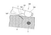
針スライダ23を操作部8の先端側へと術者が前進させることにより、図10に示すように、針管3の先端は組織に穿刺され、生検を行う対象組織Tへと押し進められる。このとき、組織の表面から外部に露出している針管3は光学撮像機構103によって観察することができる。組織の内部に差し込まれた針管3の先端側部分は超音波走査機構104によって観察することができる。 When the operator advances the
術者は、超音波走査機構104において受信された超音波に基づく超音波画像を図1に示す超音波観察部115によって観察することができる。超音波観察部115に鮮明に映し出された針管3の像を参照し、術者は、針管3の先端を、生検を行う対象組織Tに到達させる。 The surgeon can observe an ultrasonic image based on the ultrasonic wave received by the
次に、術者は、針管3内に入り込んだ生検対象でない組織をスタイレット27で押し出し、挿入体2および操作部8からスタイレット27を引き抜く。これにより、針管3の先端から針スライダ23の基端まで延びる貫通孔が生じる。術者は、針スライダ23の基端にシリンジ等を接続して針管3内を吸引し、針管3の先端から生検を行う対象組織Tの細胞などを吸引して採取する。 Next, the surgeon pushes out the tissue that has entered the
必要量の細胞などが採取できたら、針スライダ23を操作部8の基端側に後退させ、針管3の先端をシース7内に収容する。これにより、針管3は組織から抜ける。針管3が組織から抜けたら、超音波内視鏡100の操作部109の基端口金108からスライドロック51をはずし、処置具1をチャンネル107から抜去する。最後に超音波内視鏡100を患者から抜去して一連の処置を終了する。 When a necessary amount of cells or the like can be collected, the
以上に説明したように、本実施形態では、シース7の先端部分が超音波内視鏡100によって光学的に観察可能な位置関係にあるときに、遠位筒部71と近位筒部72との境界部位にあたる接続部73が湾曲部105の基端よりもさらに基端側に位置している。遠位筒部71の方が近位筒部72よりも可撓性が高くなるように、遠位筒部71と近位筒部72とに可撓性の差がつけられているので、本実施形態では、処置具1が超音波内視鏡100に取り付けられた状態において湾曲部105の湾曲性能が下がりにくく、またチャンネル107内におけるシース7の中心線方向における伸縮やシース7の蛇行が起こりにくい。 As described above, in the present embodiment, when the distal end portion of the
また、遠位筒部71の外面に密着するように配された被覆部74が、遠位筒部71を構成する素線が遠位筒部71の湾曲変形時に極端に離間するのを防ぐので、素線間に針管3の先端が入り込みにくく、針管3によるシース7の突き破りを防止できる。 Further, the covering
また、接続部73が湾曲部105の基端よりもさらに基端側にあるので、シース7の位置をチャンネル107内で調整した場合にも近位筒部72が湾曲部105内に入り込まない。このため、このような位置調整の前後で湾曲部105の湾曲能力が変動しない。 Further, since the connecting
以上、本発明の実施形態について図面を参照して詳述したが、具体的な構成はこの実施形態に限られるものではなく、本発明の要旨を逸脱しない範囲の設計変更等も含まれる。 As mentioned above, although embodiment of this invention was explained in full detail with reference to drawings, the concrete structure is not restricted to this embodiment, The design change etc. of the range which does not deviate from the summary of this invention are included.
たとえば、湾曲又は屈曲した筒状のアングルチューブ107bに代えて、上記のアングルチューブ107bと同様に湾曲又は屈曲した貫通孔(アングル部)が先端硬質部102に形成されていてもよい。この場合アングルチューブ107bは不要である。 For example, instead of the curved or bent
また、接続部73は、筒状の部材により遠位筒部71と近位筒部72とを接続することに代えて、遠位筒部71と近位筒部72とが溶接されるものであってよい。また、接続部73は、この位置において素線の構成が切り替わる単なる境界位置であってもよい。たとえば、シース7の先端から基端まで一続きに素線が巻かれたコイルにおいて上記の接続部73の位置において素線の断面積、断面形状、硬度等が切り替わることによって上記実施形態と同様の可撓性の差がつけられていてもよい。 Further, the connecting
また、処置具1は被覆部74を有していなくてもよい。 The
本発明は前述した説明によって限定されることはなく、添付の請求の範囲によってのみ限定される。 The present invention is not limited by the above description, but only by the appended claims.
本発明によれば、可撓性シースが全体として伸縮しにくく、且つ内視鏡の湾曲部の湾曲性能を低下させにくい生検システムを提供することができる。 According to the present invention, it is possible to provide a biopsy system in which the flexible sheath is less likely to expand and contract as a whole and the bending performance of the bending portion of the endoscope is unlikely to deteriorate.
1 処置具(内視鏡用処置具)
2 挿入体
3 針管
31 針管の開口
7 シース
71 遠位筒部
71a 遠位筒部の先端
71b 遠位筒部の基端
72 近位筒部
72a 近位筒部の先端
73 接続部
74 被覆部(被覆)
8 操作部
9 操作本体
18 シースアジャスター
23 針スライダ
27 スタイレット(芯金)
27a ツマミ
27b 芯
51 スライドロック
52 ホルダ(固定部)
52a、52b 一対の壁部
53 支持パイプ
54 固定ネジ
61 ストッパ
62 固定ネジ
100 超音波内視鏡
101 挿入部
102 先端硬質部
103 光学撮像機構(撮像部)
104 超音波走査機構
105 湾曲部
106 可撓管部
107 チャンネル
107a スロープ部
107b アングルチューブ(アングル部)
107c チャンネルチューブ
108 基端口金
109 操作部
110 湾曲操作機構
111 複数のスイッチ
112 ユニバーサルコード
113 光源装置
114 光学的観察部
115 超音波観察部
116 モニター
150 生検システム1 treatment tool (endoscopic treatment tool)
2
8 Operation section 9
52a, 52b A pair of
104
Claims (5)
Translated fromJapanese前記チャンネル内に挿通可能な内視鏡用処置具と、
を備えた生検システムであって、
前記内視鏡用処置具は、
前記チャンネル内に挿通可能であり可撓性を有する筒状のシースと、
生検のために組織に穿刺可能な鋭利な端部を有し前記シースの内部に配された針管と、
前記針管の近位端に接続された針スライダと、前記シースの近位端に接続された操作本体と、を有し、前記針スライダが前記操作本体に対して移動することで、前記シースの内部で前記針管を移動させ、前記針管を前記シースの遠位端から突没させる操作部と、
を有し、
前記シースは、
前記シースの遠位端を含む前記シースの遠位部分に配された遠位筒部と、
前記遠位筒部の近位端に固定され前記遠位筒部と同軸をなし前記遠位筒部よりも可撓性が低い近位筒部と、
前記遠位筒部と前記近位筒部とを接続する接続部と、
を有し、
前記遠位筒部と前記近位筒部との境界部位は、前記シースの遠位端が前記チャンネルの遠位端から突出して前記内視鏡により光学的に観察可能である位置関係において前記能動湾曲部の近位端よりも近位側に位置している
生検システム。An endoscope provided with an insertion portion having a channel and inserted into the body, and an active bending portion arranged in a part of the insertion portion and actively bending and deforming a part of the channel;
An endoscopic treatment tool that can be inserted into the channel;
A biopsy system comprising
The endoscopic treatment tool is:
A cylindrical sheath that can be inserted into the channel and has flexibility;
A needle tube having a sharp end that can be punctured into tissue for biopsy and disposed within the sheath;
A needle slider connected to the proximal end of the needle tube, and an operation body connected to the proximal end of the sheath, and the needle slider moves relative to the operation body ,An operation unit for moving theneedle tube therein and projecting and retracting the needle tube from a distal end of the sheath ;
Have
The sheath is
A distal barrel disposed in a distal portion of the sheath including a distal end of the sheath;
A proximal cylinder fixed to the proximal end of the distal cylinder and coaxial with the distal cylinder and less flexible than the distal cylinder;
A connecting portion connecting the distal tube portion and the proximal tube portion;
Have
The boundary portion between the distal tube portion and the proximal tube portion is active in a positional relationship in which the distal end of the sheath projects from the distal end of the channel and can be optically observed by the endoscope. A biopsy system located proximal to the proximal end of the bend.
前記接続部は、前記遠位筒部の近位端と前記近位筒部の遠位端とがともに内部に配された筒状部材であり、
前記遠位筒部は、
前記接続部に固定された可撓性のコイルと、
前記コイルの外周面を覆うように前記コイルに取り付けられた被覆と、
を有し、
前記被覆の外径と前記接続部の外径との差は前記近位筒部の外径と前記接続部の外径との差よりも小さい
生検システム。The biopsy system according to claim 1,
The connection part is a cylindrical member in which a proximal end of the distal cylinder part and a distal end of the proximal cylinder part are both arranged inside,
The distal cylinder is
A flexible coil fixed to the connecting portion;
A coating attached to the coil so as to cover the outer peripheral surface of the coil;
Have
A biopsy system in which a difference between an outer diameter of the covering and an outer diameter of the connection portion is smaller than a difference between an outer diameter of the proximal tube portion and an outer diameter of the connection portion.
前記遠位筒部の中心線方向における単位長さあたりの前記遠位筒部の自重による弾性変形量は、前記近位筒部の中心線方向における単位長さあたりの前記遠位筒部の自重による弾性変形量よりも大きい
生検システム。A biopsy system according to claim 2,
The amount of elastic deformation due to the weight of the distal cylinder per unit length in the centerline direction of the distal cylinder is determined by the weight of the distal cylinder per unit length in the centerline direction of the proximal cylinder Greater than the amount of elastic deformation caused by the biopsy system.
前記被覆の外周面は前記コイルの外周面に倣って凹凸形状を有する
生検システム。A biopsy system according to claim 3,
The biopsy system, wherein the outer peripheral surface of the coating has an uneven shape following the outer peripheral surface of the coil.
前記内視鏡は、
前記内視鏡用処置具及び生検対象部位を撮像可能な撮像部と、
前記撮像部よりも遠位側に配された超音波走査機構と、
を有し、
前記チャンネルは、
前記シースを前記超音波走査機構の走査範囲に向けて屈曲させるように前記挿入部の中心線に対して傾斜されたスロープ部と、
前記挿入部の中心線と平行なチャンネルチューブと、
前記スロープ部と前記チャンネルチューブを繋ぐアングル部と、
を有し、
前記シースの遠位端が前記チャンネルの前記遠位端から突出して前記内視鏡により光学的に観察可能である前記位置関係において、前記針管の前記端部は前記操作部によって近位側に限界まで移動されたときに、前記能動湾曲部よりも遠位側且つ前記スロープ部より近位側に位置している
生検システム。A biopsy system according to claim 4,
The endoscope is
An imaging unit capable of imaging the endoscopic treatment tool and a biopsy target site;
An ultrasonic scanning mechanism disposed on the distal side of the imaging unit;
Have
The channel is
A slope portion inclined with respect to the center line of the insertion portion so as to bend the sheath toward the scanning range of the ultrasonic scanning mechanism;
A channel tube parallel to the center line of the insertion portion;
An angle part connecting the slope part and the channel tube;
Have
In the positional relationship where the distal end of the sheath protrudes from the distal end of the channel and can be optically observed by the endoscope, the end of the needle tube is limited to the proximal side by the operating portion. A biopsy system that is located distal to the active bend and proximal to the slope when moved to.
Applications Claiming Priority (3)
| Application Number | Priority Date | Filing Date | Title |
|---|---|---|---|
| JP2014119922 | 2014-06-10 | ||
| JP2014119922 | 2014-06-10 | ||
| PCT/JP2015/063104WO2015190188A1 (en) | 2014-06-10 | 2015-05-01 | Biopsy system |
Publications (2)
| Publication Number | Publication Date |
|---|---|
| JP5953441B2true JP5953441B2 (en) | 2016-07-20 |
| JPWO2015190188A1 JPWO2015190188A1 (en) | 2017-04-20 |
Family
ID=54833293
Family Applications (1)
| Application Number | Title | Priority Date | Filing Date |
|---|---|---|---|
| JP2015551078AActiveJP5953441B2 (en) | 2014-06-10 | 2015-05-01 | Biopsy system |
Country Status (5)
| Country | Link |
|---|---|
| US (1) | US20160367231A1 (en) |
| EP (1) | EP3155952B1 (en) |
| JP (1) | JP5953441B2 (en) |
| CN (1) | CN106102545B (en) |
| WO (1) | WO2015190188A1 (en) |
Cited By (1)
| Publication number | Priority date | Publication date | Assignee | Title |
|---|---|---|---|---|
| KR102459425B1 (en)* | 2022-03-28 | 2022-10-27 | 주식회사 큐어인 | A biopsy needle module for real-time biopsy using a medical imaging equipment |
Families Citing this family (16)
| Publication number | Priority date | Publication date | Assignee | Title |
|---|---|---|---|---|
| JP6542102B2 (en)* | 2015-11-09 | 2019-07-10 | 富士フイルム株式会社 | Endoscope |
| US20200077991A1 (en)* | 2016-05-31 | 2020-03-12 | Intuitive Surgical Operations, Inc. | Pliant biopsy needle system |
| EP3871586B1 (en)* | 2016-12-07 | 2023-03-22 | Boston Scientific Scimed, Inc. | Systems for eccentric nodule tissue acquisition |
| WO2018179846A1 (en)* | 2017-03-31 | 2018-10-04 | 富士フイルム株式会社 | Ultrasonic endoscope |
| WO2018220850A1 (en)* | 2017-06-02 | 2018-12-06 | オリンパス株式会社 | Endoscope puncture needle |
| WO2019186285A2 (en)* | 2018-03-14 | 2019-10-03 | Hoya Corporation | Covered coil sheath for biopsy needle, biopsy needle assembly, and method of forming covered coil sheath |
| US11166625B2 (en)* | 2018-03-26 | 2021-11-09 | Spiration, Inc. | Sheath with detectable leader |
| US11065372B2 (en) | 2018-03-27 | 2021-07-20 | Gyrus Acmi, Inc. | Needle system restrictor |
| US11071530B2 (en) | 2018-03-27 | 2021-07-27 | Gyrus Acmi, Inc. | Needle system restrictor |
| CN111970975B (en)* | 2018-03-29 | 2024-04-09 | 泰尔茂株式会社 | Photographing apparatus |
| US11819199B2 (en) | 2018-04-30 | 2023-11-21 | Boston Scientific Scimed, Inc. | Ramped biopsy needle device |
| US11280976B2 (en)* | 2018-05-11 | 2022-03-22 | Ppc Broadband Fiber Ltd. | Fiber splice closure having a raised deck covering a splitter |
| WO2019246275A1 (en)* | 2018-06-19 | 2019-12-26 | Boston Scientific Scimed, Inc. | Endoscopic suturing device and associated control handle |
| US12096915B2 (en)* | 2019-03-11 | 2024-09-24 | Gyrus Acmi, Inc. | Sheath location indicator and overextension preventer |
| US20220133138A1 (en)* | 2020-10-29 | 2022-05-05 | Clearmind Biomedical, Inc. | Dilator-less and obturator-less introducer for viewing and acting on internal passageways or tissue |
| WO2024173228A1 (en)* | 2023-02-13 | 2024-08-22 | Endosound, Inc. | Devices, systems, and methods for guiding an endoscope instrument and selectively moving an attachable ultrasound assembly |
Citations (3)
| Publication number | Priority date | Publication date | Assignee | Title |
|---|---|---|---|---|
| JPH05253178A (en)* | 1992-03-16 | 1993-10-05 | Asahi Optical Co Ltd | Injection means for endoscope |
| JPH11244223A (en)* | 1998-03-06 | 1999-09-14 | Asahi Optical Co Ltd | Endoscope treatment instrument insertion channel |
| JP2012161591A (en)* | 2011-01-19 | 2012-08-30 | Fujifilm Corp | Endoscope |
Family Cites Families (8)
| Publication number | Priority date | Publication date | Assignee | Title |
|---|---|---|---|---|
| JPH11128233A (en)* | 1997-10-28 | 1999-05-18 | Olympus Optical Co Ltd | Tissue puncture needle |
| JPH11276422A (en)* | 1998-03-31 | 1999-10-12 | Fuji Photo Optical Co Ltd | Ultrasonic endoscope |
| JP4618410B2 (en)* | 2004-07-06 | 2011-01-26 | 富士フイルム株式会社 | Ultrasound endoscope |
| US9980707B2 (en)* | 2011-04-04 | 2018-05-29 | Cook Medical Technologies Llc | Endoscopic ultrasound-guided biopsy needle |
| JP2012120573A (en)* | 2010-12-06 | 2012-06-28 | Olympus Corp | Endoscope |
| JP5379249B2 (en)* | 2012-01-13 | 2013-12-25 | 富士フイルム株式会社 | Tissue collection device |
| CN103930044B (en)* | 2012-03-08 | 2016-05-18 | 奥林巴斯株式会社 | guide sheath and medical system |
| US9295454B2 (en)* | 2012-09-21 | 2016-03-29 | Ko-Pen Wang | Double lumen or double wire endobronchial ultrasound-guided histology needle (EBUS) |
- 2015
- 2015-05-01JPJP2015551078Apatent/JP5953441B2/enactiveActive
- 2015-05-01CNCN201580012624.8Apatent/CN106102545B/enactiveActive
- 2015-05-01WOPCT/JP2015/063104patent/WO2015190188A1/enactiveApplication Filing
- 2015-05-01EPEP15806899.9Apatent/EP3155952B1/enactiveActive
- 2016
- 2016-08-29USUS15/250,445patent/US20160367231A1/ennot_activeAbandoned
Patent Citations (3)
| Publication number | Priority date | Publication date | Assignee | Title |
|---|---|---|---|---|
| JPH05253178A (en)* | 1992-03-16 | 1993-10-05 | Asahi Optical Co Ltd | Injection means for endoscope |
| JPH11244223A (en)* | 1998-03-06 | 1999-09-14 | Asahi Optical Co Ltd | Endoscope treatment instrument insertion channel |
| JP2012161591A (en)* | 2011-01-19 | 2012-08-30 | Fujifilm Corp | Endoscope |
Cited By (1)
| Publication number | Priority date | Publication date | Assignee | Title |
|---|---|---|---|---|
| KR102459425B1 (en)* | 2022-03-28 | 2022-10-27 | 주식회사 큐어인 | A biopsy needle module for real-time biopsy using a medical imaging equipment |
Also Published As
| Publication number | Publication date |
|---|---|
| EP3155952A4 (en) | 2018-03-14 |
| EP3155952B1 (en) | 2019-10-02 |
| WO2015190188A1 (en) | 2015-12-17 |
| US20160367231A1 (en) | 2016-12-22 |
| CN106102545A (en) | 2016-11-09 |
| JPWO2015190188A1 (en) | 2017-04-20 |
| CN106102545B (en) | 2018-04-13 |
| EP3155952A1 (en) | 2017-04-19 |
Similar Documents
| Publication | Publication Date | Title |
|---|---|---|
| JP5953441B2 (en) | Biopsy system | |
| JP5629043B1 (en) | Biopsy system | |
| US9820724B2 (en) | Endoscope puncture needle and biopsy system | |
| JP5249472B2 (en) | Biopsy treatment tool | |
| US9913632B2 (en) | Puncture needle for endoscope | |
| WO2016047202A1 (en) | Endoscope puncture needle | |
| WO2016136080A1 (en) | Endoscope puncture needle | |
| WO2016152192A1 (en) | Biopsy system and treatment instrument | |
| JP5861020B1 (en) | Ultrasound biopsy needle | |
| WO2016042849A1 (en) | Biopsy system | |
| JP5861019B1 (en) | Ultrasound biopsy needle | |
| JP6284464B2 (en) | Endoscopic puncture needle | |
| WO2015190187A1 (en) | Endoscopic treatment instrument and biopsy system | |
| JP5985131B1 (en) | Endoscopic puncture needle and biopsy system | |
| WO2018220850A1 (en) | Endoscope puncture needle | |
| WO2020234919A1 (en) | Endoscope puncture needle | |
| JP5893814B1 (en) | Tissue collection system | |
| JP5985128B1 (en) | Biopsy system and treatment tool |
Legal Events
| Date | Code | Title | Description |
|---|---|---|---|
| A521 | Request for written amendment filed | Free format text:JAPANESE INTERMEDIATE CODE: A821 Effective date:20151014 | |
| A621 | Written request for application examination | Free format text:JAPANESE INTERMEDIATE CODE: A621 Effective date:20151013 | |
| A871 | Explanation of circumstances concerning accelerated examination | Free format text:JAPANESE INTERMEDIATE CODE: A871 Effective date:20151013 | |
| A975 | Report on accelerated examination | Free format text:JAPANESE INTERMEDIATE CODE: A971005 Effective date:20160118 | |
| A131 | Notification of reasons for refusal | Free format text:JAPANESE INTERMEDIATE CODE: A131 Effective date:20160126 | |
| A521 | Request for written amendment filed | Free format text:JAPANESE INTERMEDIATE CODE: A523 Effective date:20160303 | |
| A521 | Request for written amendment filed | Free format text:JAPANESE INTERMEDIATE CODE: A821 Effective date:20160304 | |
| TRDD | Decision of grant or rejection written | ||
| A01 | Written decision to grant a patent or to grant a registration (utility model) | Free format text:JAPANESE INTERMEDIATE CODE: A01 Effective date:20160531 | |
| A61 | First payment of annual fees (during grant procedure) | Free format text:JAPANESE INTERMEDIATE CODE: A61 Effective date:20160613 | |
| R151 | Written notification of patent or utility model registration | Ref document number:5953441 Country of ref document:JP Free format text:JAPANESE INTERMEDIATE CODE: R151 | |
| R250 | Receipt of annual fees | Free format text:JAPANESE INTERMEDIATE CODE: R250 | |
| R250 | Receipt of annual fees | Free format text:JAPANESE INTERMEDIATE CODE: R250 | |
| R250 | Receipt of annual fees | Free format text:JAPANESE INTERMEDIATE CODE: R250 | |
| R250 | Receipt of annual fees | Free format text:JAPANESE INTERMEDIATE CODE: R250 | |
| R250 | Receipt of annual fees | Free format text:JAPANESE INTERMEDIATE CODE: R250 | |
| R250 | Receipt of annual fees | Free format text:JAPANESE INTERMEDIATE CODE: R250 | |
| R250 | Receipt of annual fees | Free format text:JAPANESE INTERMEDIATE CODE: R250 |