JP5953421B2 - Management method of tenant network configuration in virtual server and non-virtual server mixed environment - Google Patents
Management method of tenant network configuration in virtual server and non-virtual server mixed environmentDownload PDFInfo
- Publication number
- JP5953421B2 JP5953421B2JP2015501211AJP2015501211AJP5953421B2JP 5953421 B2JP5953421 B2JP 5953421B2JP 2015501211 AJP2015501211 AJP 2015501211AJP 2015501211 AJP2015501211 AJP 2015501211AJP 5953421 B2JP5953421 B2JP 5953421B2
- Authority
- JP
- Japan
- Prior art keywords
- virtual
- physical
- instance
- network
- gateway
- Prior art date
- Legal status (The legal status is an assumption and is not a legal conclusion. Google has not performed a legal analysis and makes no representation as to the accuracy of the status listed.)
- Expired - Fee Related
Links
Images


Classifications
- G—PHYSICS
- G06—COMPUTING OR CALCULATING; COUNTING
- G06F—ELECTRIC DIGITAL DATA PROCESSING
- G06F9/00—Arrangements for program control, e.g. control units
- G06F9/06—Arrangements for program control, e.g. control units using stored programs, i.e. using an internal store of processing equipment to receive or retain programs
- G06F9/44—Arrangements for executing specific programs
- G06F9/455—Emulation; Interpretation; Software simulation, e.g. virtualisation or emulation of application or operating system execution engines
- G06F9/45533—Hypervisors; Virtual machine monitors
- G06F9/45558—Hypervisor-specific management and integration aspects
- H—ELECTRICITY
- H04—ELECTRIC COMMUNICATION TECHNIQUE
- H04L—TRANSMISSION OF DIGITAL INFORMATION, e.g. TELEGRAPHIC COMMUNICATION
- H04L12/00—Data switching networks
- H04L12/28—Data switching networks characterised by path configuration, e.g. LAN [Local Area Networks] or WAN [Wide Area Networks]
- H04L12/46—Interconnection of networks
- H04L12/4641—Virtual LANs, VLANs, e.g. virtual private networks [VPN]
- G—PHYSICS
- G06—COMPUTING OR CALCULATING; COUNTING
- G06F—ELECTRIC DIGITAL DATA PROCESSING
- G06F9/00—Arrangements for program control, e.g. control units
- G06F9/06—Arrangements for program control, e.g. control units using stored programs, i.e. using an internal store of processing equipment to receive or retain programs
- G06F9/44—Arrangements for executing specific programs
- G06F9/455—Emulation; Interpretation; Software simulation, e.g. virtualisation or emulation of application or operating system execution engines
- G06F9/45533—Hypervisors; Virtual machine monitors
- G06F9/45558—Hypervisor-specific management and integration aspects
- G06F2009/45595—Network integration; Enabling network access in virtual machine instances
Landscapes
- Engineering & Computer Science (AREA)
- Software Systems (AREA)
- Theoretical Computer Science (AREA)
- Physics & Mathematics (AREA)
- General Engineering & Computer Science (AREA)
- General Physics & Mathematics (AREA)
- Computer Security & Cryptography (AREA)
- Computer Networks & Wireless Communication (AREA)
- Signal Processing (AREA)
- Data Exchanges In Wide-Area Networks (AREA)
Description
Translated fromJapanese本発明は一般的には計算機システムに関連し、より具体的には仮想サーバおよび物理サーバが混在する計算機システムにおいて、ネットワークを始めとしたリソースの構成を管理する方法および装置に関連する。 The present invention generally relates to a computer system, and more specifically to a method and apparatus for managing the configuration of resources such as a network in a computer system in which virtual servers and physical servers are mixed.
サーバ仮想化技術が普及し、企業情報システムを構築するための複数の仮想サーバを単一のハードウェア上(単一の物理サーバ)に統合することが一般的となった。サーバ仮想化技術によれば、従来物理サーバに一対一に関連付けられていた物理サーバの物理リソース(CPU、メモリなど)を、複数サーバリソースに分割し、各サーバリソースに仮想サーバを独立して動作させるなどして、有効活用できる。さらには、物理リソースの仮想サーバへの割り当て量を柔軟に変更したり、仮想サーバを別の物理サーバ(仮想化機能を融資、複数の仮想サーバを動作させることのできる物理サーバ、以降このような物理サーバを「仮想サーバホスト」という)へと移動させることで、仮想サーバ上のアプリケーションが提供するサービスの需要に応じたリソース配分とすることができる。しかし、仮想サーバは単一の仮想サーバホストが提供するリソースを共有しているために、同じ仮想サーバホスト上の他の仮想サーバから性能上の影響を受ける。 Server virtualization technology has become widespread, and it has become common to integrate multiple virtual servers for building enterprise information systems onto a single piece of hardware (single physical server). According to the server virtualization technology, the physical resources (CPU, memory, etc.) of the physical server that has been related to the physical server in a one-to-one manner are divided into multiple server resources, and the virtual server operates independently for each server resource. Can be used effectively. Furthermore, the allocation amount of physical resources to a virtual server can be flexibly changed, or a virtual server can be changed to another physical server (a physical server that can operate a plurality of virtual servers by financing a virtualization function). By moving the physical server to the “virtual server host”), it is possible to allocate resources according to the demand for the service provided by the application on the virtual server. However, since a virtual server shares resources provided by a single virtual server host, it is affected by performance from other virtual servers on the same virtual server host.
そこで、仮想サーバが存在する環境であっても、ハイパバイザ(複数の仮想サーバを単一の物理サーバ上で動作させる機能を有するソフトウェア)を有さない物理サーバをそのまま処理環境として利用する運用方法が考えられる。ハイパバイザを有さない物理サーバは一つのハードウェア装置(物理サーバ)が持つ物理リソースを占有するので、処理性能を全て活用することができ、さらに他のサーバから影響を受けることなく安定稼働させることができる。ここでは、それら物理サーバを非仮想サーバ、あるいはベアメタルサーバと呼ぶ。非仮想サーバは、前述のように性能面における利点があるものの、複数の仮想サーバを動作させることのできる仮想サーバホストと比較しシステム構築の柔軟性に欠く。 一方、近年の傾向として、クラウドコンピューティングの隆盛がある。クラウドでは多数のサーバを仮想化によりプラットフォームに集約、統合管理することで運用管理コストを削減し、情報システムへの依存度の高まりに応えている。そのようなクラウドの特長として、ユーザのマルチテナント管理を強化している点が挙げられる。 Therefore, even in an environment where virtual servers exist, there is an operation method in which a physical server that does not have a hypervisor (software having a function of operating a plurality of virtual servers on a single physical server) is directly used as a processing environment. Conceivable. A physical server that does not have a hypervisor occupies the physical resources of a single hardware device (physical server), so all processing performance can be used, and stable operation is not affected by other servers. Can do. Here, these physical servers are called non-virtual servers or bare metal servers. As described above, the non-virtual server has an advantage in performance, but lacks flexibility in system construction as compared with a virtual server host capable of operating a plurality of virtual servers. On the other hand, as a recent trend, there is a rise of cloud computing. In the cloud, a large number of servers are integrated into a platform by virtualization and integrated management, thereby reducing operational management costs and responding to the growing dependence on information systems. One feature of such a cloud is that it strengthens multi-tenant management for users.
テナントは、特定のユーザグループや組織ごとに、クラウドが提供するリソースやサービスメニューを関連付けるものである。複数のテナントが一つのクラウド基盤を共有することで、プラットフォーム全体の利用効率を高めることができる。このとき、他のテナントが自身のテナントのリソースに不正にアクセスできないよう、セキュリティを保護する仕組みが必要不可欠である。一般的なクラウドシステムでは、ユーザ認証やネットワークの分割により、テナントごとにセキュリティが確保される。ネットワーク上にはネットワークポリシを設定する管理装置が配置されており、テナントやユーザ、仮想サーバの用途に応じてサーバ間の通信の許可・不許可を制御する。このようなネットワーク構成管理装置は、テナントや仮想サーバの需要に応じて柔軟に作成・変更可能である必要があり、ネットワークアプライアンスと呼ばれる仮想サーバとして実現される。
また、性能の観点においても、他のテナントで稼働する業務システムの稼働状態に影響されず、安定的に稼働する仕組みが必要である。仮想サーバ環境においては、仮想サーバのオンライン移行を利用した負荷分散や、仮想サーバごとの通信の優先度制御などにより、安定稼働を実現する動きが一般的である。A tenant associates resources and service menus provided by the cloud for each specific user group or organization. Multiple tenants can share the same cloud platform to increase the overall platform usage efficiency. At this time, a mechanism for protecting security is indispensable so that other tenants cannot illegally access their tenant resources. In a general cloud system, security is ensured for each tenant by user authentication and network division. A management device for setting a network policy is arranged on the network, and controls permission / denial of communication between servers according to the use of a tenant, a user, and a virtual server. Such a network configuration management device needs to be able to be created and changed flexibly according to the demands of tenants and virtual servers, and is realized as a virtual server called a network appliance.
Also, from the viewpoint of performance, a system that operates stably without being affected by the operating state of a business system that operates in another tenant is necessary. In a virtual server environment, a movement for realizing stable operation is generally performed by load distribution using online migration of a virtual server, priority control of communication for each virtual server, or the like.
前述の通り、多数のテナントを一つのプラットフォームに集約した環境では、リソース利用効率が高まる一方、処理性能の確保が課題となる。非仮想サーバの活用は、安定的な計算処理性能を得るための一つの解決策であるが、ディスクIO性能やネットワーク性能についても同様に性能を高める工夫が必要不可欠である。その上、それら多岐の項目にわたるリソース構成は、時々刻々と変化するプラットフォーム全体の利用状況に合わせて適切に変更されなければならない。
例えば、特許文献1はネットワーク上の通信負荷を分散するルータの構成方法およびシステムを開示している。同システムにより、複数のネットワーク経路を並行して利用でき、ネットワークリソースを有効に活用することができる。また、特許文献2は、マルチテナント環境において効率的に構成を管理する方法を開示している。As described above, in an environment in which a large number of tenants are integrated into one platform, resource utilization efficiency increases, but securing processing performance becomes an issue. Utilization of non-virtual servers is one solution for obtaining stable calculation processing performance, but it is indispensable to improve the disk IO performance and network performance as well. In addition, the resource structure across these various items must be changed appropriately according to the usage of the entire platform, which changes from moment to moment.
For example,
従来技術、同一テナントに非仮想サーバと仮想サーバホスト上で動作する仮想サーバとを混在させた場合のネットワークリソース管理方法を提供する技術は開示されていない。これは、従来、一部のワークロードに対して性能の安定化を実現する目的で、非仮想サーバを仮想サーバが構成しているものと同じテナントネットワークに接続して活用するという発想そのものがなかったためである。 Conventional techniques and techniques for providing a network resource management method when a non-virtual server and a virtual server operating on a virtual server host are mixed in the same tenant are not disclosed. In the past, there was no idea of connecting non-virtual servers to the same tenant network that the virtual servers are configured to use for the purpose of stabilizing performance for some workloads. This is because.
本発明の目的は、非仮想サーバと仮想サーバを同じテナントで運用し、セキュリティ面および性能面での独立性を確保しながら、ユーザの要求に応じて性能とコストが最適化された情報システムを構築することである。 An object of the present invention is to operate an information system in which a non-virtual server and a virtual server are operated by the same tenant, and security and performance independence are ensured, and performance and cost are optimized according to user requirements. Is to build.
管理コンピュータは、複数の仮想インスタンス(仮想サーバ)および当該仮想インスタンス間のネットワークを制御する仮想スイッチが動作する第1の物理サーバと、物理インスタンスが動作する第2の物理サーバと、第1の物理サーバと第2の物理サーバと接続され、第1の物理サーバおよび第2の物理サーバ間のネットワークを制御する物理スイッチと、に接続される。そして、管理コンピュータは、複数の仮想インスタンスのそれぞれについて当該仮想インスタンスが接続する内部ネットワークとの対応関係を示す仮想スイッチ管理情報と、物理インスタンスと当該物理インスタンスが接続する内部ネットワークとの対応関係を示す物理スイッチ管理情報とを備える。そして管理コンピュータは前記物理インスタンスと同じ内部ネットワークに接続する第1の仮想インスタンスを作成するための第1のインスタンス作成要求を受信すると、第1の物理サーバ上に前記第1の仮想インスタンスを作成し、物理スイッチ管理情報を参照して、前記物理インスタンスが接続する第1の内部ネットワークを特定し、前記第1の仮想インスタンスが前記第1の内部ネットワークに接続されるように前記仮想スイッチと前記物理スイッチを設定する。 The management computer includes a first physical server on which a virtual switch that controls a plurality of virtual instances (virtual servers) and a network between the virtual instances, a second physical server on which the physical instances operate, and a first physical server The server is connected to the second physical server, and is connected to a physical switch that controls the network between the first physical server and the second physical server. Then, the management computer indicates virtual switch management information indicating the correspondence between each of the plurality of virtual instances and the internal network to which the virtual instance is connected, and indicates the correspondence between the physical instance and the internal network to which the physical instance is connected. Physical switch management information. When the management computer receives a first instance creation request for creating a first virtual instance connected to the same internal network as the physical instance, the management computer creates the first virtual instance on the first physical server. The physical switch management information is referred to, the first internal network to which the physical instance is connected is specified, and the virtual switch and the physical are connected so that the first virtual instance is connected to the first internal network. Set the switch.
本発明によれば、ユーザにそれぞれセキュリティが確保されたテナントが提供されながらも、複数のテナントを同じ物理ハードウェア上で稼働させることができる。そして、非仮想サーバと仮想サーバとを同じテナントで運用し、セキュリティ面および性能面での独立性を確保しながら、ユーザの要求に応じて性能とコストが最適化された情報システムを構築できることができる。非仮想サーバを仮想サーバと同じテナントとして活用することにより、他のテナントからセキュリティを確保しながら、ユーザが利用する多数の業務システムに対して、その時々の処理要求に応じて、性能要求の低い処理をサーバ仮想化により少数の物理装置に集約したり、性能要求が高い処理を非仮想サーバで安定的に稼働させたりするといった使い分けが可能となる。つまり、サーバ上に稼動させるアプリケーションのライフサイクルに応じてリソース構成を変更し、全体最適な情報システムを構築することができる。例えば、需要が予測できないサービス開始時には仮想サーバを利用して柔軟にリソースを増減させ、徐々に需要がある程度に定まってきた時には非仮想サーバでサービス安定稼働させ、さらに次期システムへの移行が近くなれば仮想サーバへ集約してリソース利用効率の高める、といった運用が実現できる。 According to the present invention, it is possible to operate a plurality of tenants on the same physical hardware while providing a user with a tenant in which security is ensured. And, it is possible to construct an information system that optimizes performance and cost according to the user's request while operating non-virtual server and virtual server in the same tenant and ensuring independence in security and performance. it can. By utilizing non-virtual servers as the same tenant as the virtual server, the performance requirements are low for many business systems used by users according to the processing requests from time to time while ensuring security from other tenants. It is possible to selectively use processes such as consolidating processes into a small number of physical devices by server virtualization, or stably operating processes with high performance requirements on non-virtual servers. That is, it is possible to change the resource configuration in accordance with the life cycle of the application running on the server and construct an overall optimum information system. For example, resources can be flexibly increased / decreased using virtual servers at the start of services where demand is unpredictable, and services can be stably operated on non-virtual servers when demand gradually reaches a certain level. For example, it is possible to realize operations such as concentrating to virtual servers to improve resource utilization efficiency.
本実施例によれば、仮想サーバから構成されるクラウド環境において、非仮想サーバを混在させて利用するために、共通のネットワークを動的に構成するシステムが提供される。特に、仮想サーバおよび非仮想サーバの作成手順と、その構成手順の一部として行われるネットワークの構成手順を、以下に説明する。
<物理構成および論理構成>
図1は、本実施例における計算機システムの全体像を示す。According to the present embodiment, a system for dynamically configuring a common network is provided in order to use a mixture of non-virtual servers in a cloud environment composed of virtual servers. In particular, a procedure for creating a virtual server and a non-virtual server and a network configuration procedure performed as part of the configuration procedure will be described below.
<Physical configuration and logical configuration>
FIG. 1 shows an overview of a computer system in this embodiment.
同図において、サーバ上のアプリケーションによるサービスを受けるユーザは、クライアントコンピュータ70を利用する。一つ以上のクライアントコンピュータ70は、WAN(Wide Area Network)302、およびLAN(Local Area Network)300を介して一つ以上の物理サーバ10および20と通信できるよう、物理的に接続される。 In the figure, a user who receives a service from an application on a server uses a
本実施例では、主に物理サーバ10が接続される(サービス用の)LAN300などと、クライアントコンピュータ70が接続されるWAN302などとを区別し、説明のため前者を内部ネットワーク、後者を外部ネットワークと呼ぶ。
内部ネットワークと外部ネットワークとの境界には物理ゲートウェイ500が介在し、同物理ゲートウェイ500に流れる通信データに対して様々な処理を行い、通信を制御する。ゲートウェイの構成およびゲートウェイが有する機能についての詳細は後述する。説明を簡略化するため、図1は単純な構成をとるが、必要に応じてゲートウェイが多段であってもよいし、WAN302が別のLANであってもよい。さらには、WANやLANが複数のネットワークに物理分割または論理分割されていてもよい。In this embodiment, the LAN 300 (for service) to which the
A
また、管理用のLAN301を介して、管理コンピュータと、その他各装置(例えば物理サーバ10、およびストレージ装置100)の管理インタフェースが相互に接続される。 Also, the management computer and management interfaces of other devices (for example, the
一つ以上の物理サーバ10および20は、それぞれSAN(Storage Area Network)51を介してストレージ装置100に接続される。
図2は、内部ネットワークに接続される各装置の、より詳細な物理構成および論理構成を示す。図1における内部ネットワーク300は、図2においてネットワーク61として表現される。ネットワーク61には、少なくとも一つ以上の第一の物理サーバ10、第二の物理サーバ20、ストレージ装置100、管理コンピュータ200が物理的に接続される。さらに、一つ以上のゲートウェイ500がネットワーク61およびネットワーク66の境界に接続される。このとき、図2におけるネットワーク66は、図1における外部ネットワーク302にあたる。One or more
FIG. 2 shows a more detailed physical configuration and logical configuration of each device connected to the internal network. The
第一の物理サーバ10は、CPU11、メモリ12、ファイバチャネルインタフェース(FC IF)15、およびイーサネット(以下登録商標)インタゲース(Ether IF)16を備える。メモリ12には少なくともOS13aが格納され、CPU11の演算処理によって物理サーバ10で稼働するアプリケーション13bに対し処理リソースを提供する。移行、特に仮想化プログラムが稼働せず、OS13aが物理サーバ10上で直接的に稼働するという意味で、物理サーバ10を非仮想サーバまたはベアメタルサーバと呼ぶこともある。 The first
FC IF15は、ネットワーク51を介して他の装置と通信を行うためのものであり、主にストレージ資源を接続する目的で使用される。同じ目的を達成する相互接続の手段であれば、ファイバチャネル以外の通信規格を使用してもよく、また、用途によって物理的に複数設けられても、論理的に複数に分割されてもよい。Ether IF16は、ネットワーク60を介して他の装置と通信を行うためのものであり、他の物理サーバ10、20、および管理コンピュータ200と通信する目的で使用される。同じ目的を達成する相互接続の手段であれば、イーサネット以外の通信規格に準拠するものであってもよく、また、用途によって物理的に複数設けられても、論理的に複数に分割されてもよい。 The
第二の物理サーバ20は、CPU21、メモリ22、FC IF25、およびEther IF26を備える。メモリ22には少なくともOS23aおよび仮想化プログラム23bが格納され、CPU21の演算処理によって、物理サーバ20が有する物理リソースを一つ以上の仮想的なリソース領域に分割してその他のOSまたはアプリケーション23cへ提供する。仮想化プログラム23bは必ずしもOS23aと分離される必要はなく、物理サーバ20を仮想的なリソース領域に分割する機能を備える限りにおいて、OS23a内部の一つのモジュールとして実装されてもよいし、またはOS23aそのものとして実装されてもよい。仮想化プログラム23bは一般にVMM(Virtual Machine Monitor)、ハイパバイザと呼ばれることもあり、以降の説明では、これらは同じものを指す。仮想化プログラム23bの機能により、物理サーバ20のハードウェアの一部が、閉じたリソース領域として切り出される。このリソース領域は、仮想マシンと呼ばれる一つの論理的なサーバのハードウェアを構成しており、第二の物理サーバ20を仮想マシンホストと呼ぶこともある。FC IF25、およびEther IF26についての詳細は、第一の物理サーバ10の場合と同様である。 The second
ネットワーク51は、一つ以上の物理サーバ10および20と、一つ以上のストレージ装置100を相互に接続するためのものである。これにより、物理サーバ10、20がストレージ装置100と通信し、アプリケーション13b、23cなどが稼働する際に必要なストレージ資源を利用可能とする。ネットワーク51上には、一つ以上のファイバチャネルスイッチ(FC SW)50が介在してもよい。FC SW50の構成は、Ether IF56が接続されたネットワーク61を介して、管理コンピュータ200により設定される。The
ネットワーク61は、主に以下三つの目的のために使用される。
第一の目的は、クライアントコンピュータ70と、物理サーバ10および20との間のサービス通信を提供することである。例えば、物理サーバ10は、クライアントコンピュータ70から処理要求や処理対象のデータを受信し、アプリケーション13bより加工または生成されたデータを再度クライアントコンピュータ70に向け送信する。The
The first purpose is to provide service communication between the
第二の目的は、サービス通信に関わる物理サーバ10および20の構成変更を行うことである。例えば、物理サーバ20上に新たなアプリケーション23cを導入したり、仮想化プログラム23b上に仮想サーバと呼ばれるリソース領域を作成したりといったことが行われる。 The second purpose is to change the configuration of the
第三の目的は、物理サーバ10、20とストレージ装置100との間のデータネットワーク51について構成を変更することである、例えば、ストレージ装置100のストレージ制御部150を通じて、ボリュームと呼ばれるストレージ資源の単位を作成し、物理サーバとの論理的な通信路を設定することで、ストレージ資源を利用可能とする。 The third purpose is to change the configuration of the
ストレージ装置100は、複数の物理ストレージデバイス101を集積したものであり、装置を集中的に制御するストレージ制御部150を備え、物理サーバなど他の装置に対してデータ格納用のストレージ資源を提供する。図2に示すように、物理ストレージデバイス101は、例えばハードディスクドライブ(HDD)や、ソリッドステートドライブと呼ばれる不揮発性の記憶デバイスが用いられる。
ストレージ制御部150は、CPU151、メモリ152、キャッシュ154、FC IF155、Ether IF156、Serial Advanced Technology Attachmentインタフェース(SATA IF)157を備える。メモリ152には、少なくとも読み書き要求に応答する応答プログラム153a、および装置の論理構成を制御するストレージ制御プログラム153b含むプログラムが格納され、CPU151における演算処理によりストレージ装置100の機能を実現する。キャッシュ154は、主に物理サーバの読み書き要求に対するストレージ資源の応答性能を向上されるために用いられる。FC IFはネットワーク51を介して他の装置と通信を行うためのものであり、主に物理サーバ10、20と接続する目的で使用される。同じ目的を達成する相互接続の手段であればファイバチャネル以外の通信規格を使用してもよく、また物理サーバの台数などに応じて複数あってもよい。Ether IF16は、ネットワーク60を介して他の装置と通信を行うためのものであり、主に管理コンピュータ200と接続する目的で使用される。The
The
管理コンピュータ200は、CPU201、メモリ202、Ether IF206を備え、主に他の装置の構成を変更する機能を有する。メモリ202には、少なくとも管理コンピュータのハードウェアを制御するOS203a、および管理プログラム203bが格納され、CPU201の演算処理により管理コンピュータ200の機能を実現する。管理プログラム203bは、管理コンピュータ200が許容する処理能力を超えない限り、用途に応じて複数稼働してもよい。管理プログラム203bの詳細については後述する。Ether IF206は、ネットワーク60を介して他の装置と通信を行うためのものである。 The
物理ゲートウェイ500は、内部ネットワーク61および外部ネットワーク66の境界に一つ以上存在し、同ゲートウェイを通過する通信データや内部ネットワーク内に流れる通信データに対して特定のポリシを適用する機能を有する。本実施例におけるゲートウェイとは、一般にはルータと呼ばれるものであり、例えばレイヤ3ルータ、ファイヤウォール、ネットワークアドレス変換(NAT)、プロキシ、リバースプロキシ、VPNルータ、ポートフォワーディングといった機能の一つまたは複数を実装するものである。物理ゲートウェイ500は、物理サーバ10や20、管理コンピュータ200と同様に、CPU501、メモリ502、Ether IF506を有する。メモリ502上にはOS503aや一つまたは複数のネットワーク制御プログラム503bを有し、CPU501の演算処理により物理ゲートウェイ500の機能を実現する。また、少なくとも複数のEther IF506を持ち、論理的に内部ネットワーク61側のインタフェース506aと、外部ネットワーク66側のインタフェース506bとに分類できる。ネットワーク制御プログラム503bが実現する機能の詳細については後述する。 One or more
ネットワーク66は、物理サーバ10および20や管理コンピュータ200、ストレージ装置100から見て外部ネットワークである。図2には示していないが、ネットワーク66から見てさらに外部にゲートウェイがあってもよい。また、ネットワーク66は、Ether SW65を介して構成されてもよい。
<インスタンスの構成方法>
本実施例における計算機システムは、仮想サーバおよび非仮想サーバのリソース構成を管理する機能を提供する。以下、仮想サーバおよび非仮想サーバを生成する際の構成手順を例に、システムの構成および機能を説明する。なお、ここでは、ユーザの要求に応じて生成され、クライアントに情報サービスを提供するサーバをインスタンスと呼び、仮想サーバを仮想インスタンス、非仮想サーバを物理インスタンスと呼ぶ。The
<Instance configuration method>
The computer system in this embodiment provides a function for managing the resource configuration of virtual servers and non-virtual servers. Hereinafter, the configuration and functions of the system will be described by taking the configuration procedure when generating the virtual server and non-virtual server as an example. Here, a server that is generated in response to a user request and provides an information service to a client is called an instance, a virtual server is called a virtual instance, and a non-virtual server is called a physical instance.
図3に、本実施例においてインスタンスに割り当てるリソースを制御するためのシステム構成を示す。所望のインスタンスを作成するとき、エンドユーザはクライアントコンピュータ70上の管理クライアント73bを使用して管理コンピュータ200にアクセスする。管理コンピュータ200は、管理ネットワーク302bを介してクライアントコンピュータ70と接続されており、管理プログラム203bの一種(または構成要素)である統合サービス管理部204aにおいて、管理クライアント73bが発信したインスタンス作成要求を受け付ける。統合サービス管理部204aは、各装置の構成を管理する装置管理部(サーバ管理部204b、ネットワーク管理部204c、およびストレージ管理部204b)を協調的に制御し、インスタンスを生成する働きを担う。 FIG. 3 shows a system configuration for controlling resources allocated to instances in this embodiment. When creating a desired instance, the end user accesses the
より具体的には、次のような手順でインスタンスを生成する。 More specifically, an instance is generated by the following procedure.
統合サービス管理部204aは、ストレージ管理部204dにボリュームの作成要求を発行する。このとき、ストレージ管理部204dはストレージ装置100内部に、ボリュームと呼ばれる論理的な単位でストレージ資源を確保する。適切なボリュームが既に存在している場合は、このボリューム作成手順は省略される。後述の手順を経ることで、ボリュームはサーバ装置により、例えばディスクドライブなどの不揮発性の記憶デバイスとして認識される。ボリュームが作成されると、ストレージ管理部204dは、統合サービス管理部204aに対して、ボリュームの状態や、当該ボリュームが利用可能なFC IF155の識別子などを応答する。その後、統合サービス管理部204aは、ボリューム作成手順と合わせて、インスタンスを作成するための物理サーバを選定する。仮想インスタンスが要求される場合には、ハイパバイザの構成要件に合致した物理サーバ20が選択され、物理インスタンスが要求される場合には、インスタンスの構成要件に合致した物理サーバ10が選択される。次に、統合サービス管理部204aはネットワーク管理部204cを利用して、FC SW50において通信経路の設定を行う。FC SW50は、ゾーニングと呼ばれる技術により通信可能なファイバチャネルポートを制御しており、このような設定が必要となる。これにより、選定された物理サーバ10または20が有するポート52が、ストレージ装置100上のポート52と通信可能となる。統合サービス管理部204aは、ストレージ管理部204dを利用して、Host Storage DomainやLUN Securityなどのアクセス制御機能の設定を行う。物理サーバからボリュームがディスクデバイス認識サーバ管理部を通じてOS13dまたは23dのインストーラを起動し、ディスクドライブに永続的なOS環境13aを導入する。インストーラの転送には、例えばPXEサーバやTFTPサーバを用いた一般的なネットワークインストール技術が適用できる。ユーザから要求があれば、ミドルウェアやアプリケーション23cをインストールする。このように、記憶デバイスにOS環境を新たに導入する方法の他には、既にセットアップ済みのOS環境を複製する方法があるが、詳細は後述する。 The integrated
図3に示す例では、物理インスタンス14の場合は、ストレージ装置100内のボリューム160をOS13aに接続し、アプリケーション13bが利用するデータを格納できるよう構成される。仮想インスタンスの場合には、サーバ管理部204bがハイパバイザ23bを利用して、ボリューム160内に仮想ディスク161と呼ばれるファイルを作成し、仮想インスタンス24のゲストOS23dに接続する。仮想インスタンス24のゲストOS23dからは、仮想ディスク161が提供する仮想的なディスクドライブ162が接続されたかのように認識される。これら仮想ディスク161や仮想インスタンス24の構成は、直接的にはハイパバイザ23bにより制御される。 In the example illustrated in FIG. 3, the
その他、ネットワーク管理部204cを利用して、内部ネットワーク300に接続するための、Ether SW61やEther IFの設定を行い、さらには外部ネットワーク302aに接続するためのゲートウェイ500の設定を行う。詳細についてはテナントネットワークの構成方法と合わせて後述する。 In addition, the
インスタンスの状態についての情報は、統合サービス管理部204aにより管理クライアント73bに提供され、ユーザに提示される。ユーザは、所望のサービスクライアント73aにより、サービスネットワーク302aを経由して各インスタンスの情報サービスを利用する。さらにユーザは、必要に応じて、管理クライアント73bを利用し、インスタンスの構成を変更することができる。インスタンスの構成を変更する機能は、統合サービス管理部204aおよび各装置管理部により実現される点において、上述したインスタンス作成の場合と同様である。言い換えれば、統合サービス管理部204aは、各装置管理部が備える構成変更機能を組み合わせて利用し、ユーザが必要とするインスタンスの構成変更を実施する。
<レイヤ2ネットワークの構成方法>
本発明の目的の一つは、仮想インスタンスおよび物理インスタンスをアプリケーションの要件やユーザの要求に応じて使い分けることである。そのためには、仮想インスタンスおよび物理インスタンスにまたがるプライベートネットワークを構成し、相互に通信可能でなければならない。Information about the state of the instance is provided to the
<
One of the objects of the present invention is to use a virtual instance and a physical instance in accordance with application requirements and user requirements. For this purpose, a private network that spans virtual and physical instances must be configured and able to communicate with each other.
ネットワーク装置の互換性、およびハイパバイザの仕様を考慮すると、(レイヤ2)VLANおよび(レイヤ3)ルータを利用してプライベートネットワークを構成する方法が最も一般的である。 In consideration of network device compatibility and hypervisor specifications, the most common method is to configure a private network using (Layer 2) VLAN and (Layer 3) router.
ネットワーク通信可能な範囲の制御は、レイヤ2、またはレイヤ3ネットワークの設定のみ、さらには他のレイヤでも実現可能であるが、セキュリティを確保しつつユーザの要求に応じて柔軟にプライベートネットワークを構築する方法として、本項に示す方法が広く用いられている。すなわち、性能が求められる反面、セキュリティ強度を高める必要のない内部ネットワークには、レイヤ2の接続性が確保されたネットワークを一つのレイヤ3セグメントとして構成し、アプリケーションと連携した高度なセキュリティ管理が必要な他セグメントとの外部ネットワーク通信にはレイヤ3の経路制御を利用する方法である。一つのプライベートネットワークには一つのVLANIDが付与され、別のプライベートネットワークとはレイヤ2のレベルで独立する。異なるプライベートネットワーク間を接続するには、レイヤ3ルータを介してIPアドレスを用いた通信が行われる。Control of the network communicable range can be realized only by setting the
この方法によれば、仮想インスタンスおよび物理インスタンスにまたがるプライベートネットワークがレイヤ2透過となり、例えばDHCPなどブロードキャストを用いた構成管理が利用できる。本項では、各イーサネットスイッチにおいてレイヤ2ネットワークを構成する方法について述べる。 According to this method, the private network spanning the virtual instance and the physical instance becomes
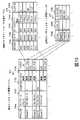
図4に、プライベートネットワークの構成例を示す。同図を用いて、以下レイヤ2ネットワークの構成方法を説明する。VLANはLANを構成する物理的に単一のネットワーク装置を、パケットに付与したVLAN IDと呼ばれる識別子に応じて論理的に多重化する技術である。VLAN IDは、スイッチ装置およびホスト上のイーサインタフェースにおいて設定・解除が可能であるが、本発明が対象とするような複数のホストが任意のタイミングで生成される環境においては、スイッチのみで制御が行われると考えてよい。イーサインタフェースで制御する方法を利用しない理由は、同方法によればOSの起動を待たなければイーサインタフェースのVLAN設定が出来ない可能性があり、OS起動以前の挙動が一時的に制御不能になるためである。 FIG. 4 shows a configuration example of the private network. A method for configuring a
すべての装置、すなわち物理サーバ10および20、イーサスイッチ60bの構成は、管理コンピュータ200により管理される。各物理スイッチ60bおよび仮想マシンホスト400および401上のハイパバイザによって実装される仮想スイッチ406および412はVLANに準拠しており、同じVLAN IDを付与することにより複数のスイッチにまたがってレイヤ2(データリンク層)の接続性を提供する。他方、異なるVLAN IDを付与することにより、レイヤ2ネットワークが分割される。例えば仮想インスタンス403の仮想Ether IF405はVLAN ID=10のネットワークに接続されており、同じVLAN ID=10のネットワークに接続される(別の仮想マシンホスト上の)仮想インスタンス410と通信可能である。一方で、同仮想インスタンス403とは別のVLAN ID=1のネットワークに接続される(同じ仮想マシンホスト上の)仮想インスタンス402とは通信不可能である。従来の仮想インスタンスのみの環境であれば、物理スイッチ60bの設定は全てのポートについて全てのVLAN IDを許可する設定(トランクオール)であればよかった。この場合、仮想インスタンス間の通信許可/不許可は仮想スイッチの設定のみで完結するため、これらの設定はハイパバイザを管理するサーバ管理部204cによって実施される。したがって、既存の仮想サーバ環境管理基盤は、物理スイッチの設定機能を持たないのが一般的である。 The configuration of all devices, that is, the
ベアメタルホスト10の場合、内部ネットワークをポートVLANにより構成する。より具体的には、物理スイッチ60bにおいて、当該ベアメタルホストが接続されているポート415にポートVLAN属性(アクセスモード)を付与する。これにより、同じVLAN IDを持つポート同士のみが通信可能となる。これらポートVLANの設定はネットワーク管理部204bによって実施される。 In the case of the
本発明が目的とするように、仮想インスタンスと物理インスタンスとの間で通信を行うには、同じVLANに両者を接続する必要がある。VLAN IDが同じであればレイヤ2の接続性が確保され、同図4の例では物理インスタンスのEther IF16a、仮想インスタンスのEther IF404がVLAN ID=1の内部ネットワーク413で疎通する。このとき、ポート415はポートVLAN属性が付与されるが、ポート416にはタグVLAN属性が付与され、しかもVLAN ID=1およびID=10のみが許可されなければならない。これは、仮想マシンホスト400に接続されるポート416において仮想インスタンス402および403両方のデータ送受信が多重化されるためである。このように、従来はトランクオールであればよかった物理スイッチの設定が、インスタンスの所在に応じて適切に制御されなければならない。さらには、物理スイッチの設定および仮想スイッチの設定は、それぞれネットワーク管理部204bおよびサーバ管理部204cのそれぞれ別の管理体系のもとに実施されるため、これらの間の整合をとる工夫が新たに必要となる。 As the object of the present invention, in order to communicate between a virtual instance and a physical instance, it is necessary to connect both to the same VLAN. If the VLAN IDs are the same,
本発明において、統合サービス管理部204aが、仮想スイッチおよび物理スイッチにおけるVLAN設定を不整合なく行う構成管理方式を提供する。より具体的には、物理スイッチのVLAN構成を管理する物理スイッチVLAN ID管理テーブル218を有するネットワーク管理部204bと、仮想スイッチのVLAN構成を管理する仮想スイッチVLAN ID管理テーブル219を有するサーバ管理部204cの両方の構成情報を参照・設定する。 In the present invention, the integrated
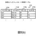
物理スイッチVLAN ID管理テーブル218を図5(a)に示す。同テーブルは、ホストID218a、スイッチID218b、ポートID218c、ポート属性218d、VLAN ID218eを格納する。これにより、物理スイッチのポート属性設定を保持する。例えば第二のレコードは、スイッチSW01上のポート#03が、VLAN ID=1およびID=10に接続されるトランクポートであることを示す。複数の物理スイッチがカスケード接続されている場合には、ホストの代わりにスイッチIDがホストIDフィールド218aに保持される。
仮想スイッチVLAN ID管理テーブル219を図5(b)に示す。同テーブルは、インスタンスID219c、スイッチID219d、ポートID219e、VLAN ID219bを格納する。これにより、物理スイッチVLAN ID管理テーブル218と同様に、仮想スイッチのポート属性設定を保持する。
これらのVLAN ID管理テーブルは管理コンピュータ200上にあり、各管理プログラムの設定に従って、各物理スイッチ装置および仮想マシンホスト上の仮想スイッチに適用される。
<処理フロー>
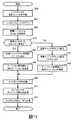
本発明に特徴的なネットワーク構成方法を、図6に示す処理フローにおいて説明する。統合サービス管理部の詳細については後述することにし、ここでは、VLANを用いたネットワーク構成の詳細手順について述べる。本処理フローの目的は、新たなインスタンスの作成を契機として、仮想インスタンスおよび物理インスタンスが混在する環境においてインスタンス間を相互に接続するプライベートネットワークを構成することである。The physical switch VLAN ID management table 218 is shown in FIG. The table stores a
The virtual switch VLAN ID management table 219 is shown in FIG. The table stores an
These VLAN ID management tables exist on the
<Processing flow>
A network configuration method characteristic of the present invention will be described with reference to the processing flow shown in FIG. Details of the integrated service management unit will be described later. Here, a detailed procedure of a network configuration using a VLAN will be described. The purpose of this processing flow is to configure a private network that interconnects instances in an environment in which virtual instances and physical instances are mixed, triggered by creation of a new instance.
さらに、本実施例における処理フローはインスタンスの追加手順を対象とし、同一VLAN内にいずれか一つ以上の既存インスタンスが稼働しているものとする。なお、新たにVLANを構成してインスタンスを新規に作成するには、いずれのVLAN ID管理テーブルにもないVLAN IDを確保して以下同様の設定を実施すればよい。 Furthermore, the processing flow in this embodiment is for the instance addition procedure, and it is assumed that any one or more existing instances are operating in the same VLAN. In order to configure a new VLAN and create a new instance, a VLAN ID that is not in any VLAN ID management table is secured, and the same setting is performed thereafter.
ユーザが管理クライアント73bを用いてインスタンス追加要求を発信すると、統合サービス管理部204aがユーザ権限を認証し、前述のインスタンスを既存のプライベートネットワーク上に作成する手順が開始される。ユーザは、または相互に接続したい既存のインスタンスを指定して、新規インスタンスの追加要求を行う。ステップ600において、前述のインスタンスを作成する手順を完了すると、ステップ601で一旦当該インスタンスをシャットダウンし、プライベートネットワークの構成手順に移る。 When the user sends an instance addition request using the
ステップ602の条件判定において、インスタンスの種別によって処理が分岐する。 In the condition determination at
物理インスタンスを新たにデプロイする場合はステップ603に進み、指定された既存のプライベートネットワークに仮想インスタンスが接続されているか、あるいは物理インスタンスが接続されているかにより、さらに処理を分岐させる。
ステップ603において仮想インスタンスが当該プライベートネットワークに接続されていると判定された場合はステップ604に進む。同ステップにおいて、統合サービス管理部204aは仮想スイッチVLAN ID管理テーブル219を参照し、指定された仮想インスタンスIDから仮想スイッチのVLAN IDを特定する。When a physical instance is newly deployed, the process proceeds to step 603, and the processing is further branched depending on whether the virtual instance is connected to the designated existing private network or whether the physical instance is connected.
If it is determined in
一方、既存の物理インスタンスが指定された場合には、処理がステップ603からステップ605へと分岐する。このとき、統合サービス管理部204aは物理スイッチVLAN ID管理テーブル218を参照し、指定された物理インスタンスID(ホストID)から物理スイッチのVLAN IDを特定する。複数の物理スイッチがカスケード接続されている場合、ホストIDフィールド218aに保持されているスイッチIDを辿って全ての必要なVLAN設定が実施される。 On the other hand, if an existing physical instance is designated, the process branches from
前ステップにおいて特定されたVLAN IDは、ステップ606において物理スイッチの当該ポートに設定される。なお、このとき当該ポートは新たに追加されたベアメタルホストに接続されるため、ポートVLAN属性が設定される。 The VLAN ID specified in the previous step is set in the relevant port of the physical switch in
以上ステップ602からステップ606までの処理フローは、例えば図4では仮想インスタンス402と相互に接続すべく物理インスタンス14を新たに作成する場合にあたる。このとき、統合サービス管理部204aは、仮想インスタンス402のインスタンスIDをもとに、仮想スイッチVLAN ID管理テーブル219を参照し、同インスタンス402が接続されている仮想スイッチ406のVLAN ID407を特定する。さらに統合サービス管理部204aは、新たに作成された物理インスタンス14が接続されるポート415に対して、同じVLAN ID418を付与する。これにより、VLAN ID=1のもと、既存の仮想インスタンス402と新たな物理インスタンス14との接続性が確立される。 The processing flow from
ユーザが仮想インスタンスの追加を要求した場合には、ステップ602からステップ607へと分岐する。先の例(ステップ603)と同様に、既存の物理インスタンスとの相互接続が指定された場合にはステップ608において物理スイッチのVLAN ID設定を参照する。あるいは既存仮想インスタンスとの相互接続が指定された場合にはステップ609に進み、当該仮想インスタンスが接続されている仮想スイッチのVLAN IDを特定する。 If the user requests to add a virtual instance, the process branches from
仮想インスタンスを追加する場合には、前ステップにおいて特定されたVLAN IDを、仮想スイッチに設定するステップ610および物理スイッチに設定するステップ611を経て、所望の既存インスタンスとの相互接続が実現される。なお、ステップ611においては、物理スイッチの当該ポートに接続されるのは仮想マシンホストであるため、タグVLAN属性が設定される。 In the case of adding a virtual instance, an interconnection with a desired existing instance is realized through the
以上ステップ602からステップ611までの処理フローは、例えば図4では仮想インスタンス410と相互に接続すべく仮想インスタンス403を新たに作成する場合にあたる。このとき、統合サービス管理部204aは、仮想インスタンス410のインスタンスIDをもとに、仮想スイッチVLAN ID管理テーブル219を参照し、同インスタンス403が接続されている仮想スイッチ406のVLAN ID408を特定する。さらに統合サービス管理部204aは、新たに作成された仮想インスタンス403が接続される仮想スイッチ406、および物理スイッチ60bのポート416および417に対して、同じVLAN ID408および419を付与する。これにより、VLAN ID=10のもと、既存の仮想インスタンス410と新たな仮想インスタンス403との接続性が確立される。 The processing flow from
ステップ612においてインスタンスを再起動すると、当該インスタンスは前述のプライベートネットワーク設定のもとで再稼働する。そのネットワーク設定は続くステップ613において、例えば同一VLAN IDが付与されたプライベートネットワーク内の他のインスタンスによるICMP受信により、疎通が確認される。 When the instance is restarted in
正常にインスタンスの追加が完了すると、ユーザへ当該インスタンスの利用開始が通知される。このとき、インスタンスにアクセスするためのユーザアカウント情報や、ネットワークアドレスを合わせてユーザへ通知してもよい。 When the addition of the instance is completed normally, the user is notified of the start of use of the instance. At this time, the user account information for accessing the instance or the network address may be notified to the user.
本実施例によれば、複数の物理スイッチおよび仮想スイッチを跨って同じVLANが定義され、物理インスタンスおよび仮想インスタンスが混在するプライベートネットワークが構成される。それらプライベートネットワークはレイヤ2のレベルで論理的に分割され、別のプライベートネットワークからのセキュリティが確保される。さらに、図4におけるネットワーク管理部204bおよびサーバ管理部204cのように、全く独立して論理ネットワークIDが管理されている場合において、これらの管理テーブルに変更を施すことなく上記の構成が実現される。 According to this embodiment, the same VLAN is defined across a plurality of physical switches and virtual switches, and a private network in which physical instances and virtual instances are mixed is configured. These private networks are logically divided at the
本実施例によれば、クラウド環境において、仮想サーバおよび非仮想サーバが混在するテナントネットワークを動的に構成するシステムが提供される。特に、仮想・非仮想サーバの使い分けにより各インスタンスに要求される性能を確保した上で、テナントごとに設定されたネットワーク制御ポリシのもとで運用することができる。
<ゲートウェイの機能>
本実施例に述べる計算機システムの目的の一つは、ユーザの役割や所属する組織などの権限に応じて、処理を行うリソースやアプリケーションへのアクセスの可否を制御することである。これにより、例えば他の組織・ユーザから自身のデータに不正にアクセスされたり、性能上の影響を受けたりすることなく、所望の業務システムを稼働させることができる。According to the present embodiment, a system for dynamically configuring a tenant network in which virtual servers and non-virtual servers are mixed is provided in a cloud environment. In particular, it is possible to operate under the network control policy set for each tenant after ensuring the performance required for each instance by properly using virtual and non-virtual servers.
<Gateway functions>
One of the purposes of the computer system described in the present embodiment is to control whether to access resources or applications to be processed according to the role of the user and the authority of the organization to which the computer system belongs. As a result, for example, a desired business system can be operated without unauthorized access to its own data from other organizations or users, or without being affected by performance.
したがって、サーバ間、あるいはクライアントとサーバを接続するネットワークにおいて、ユーザ権限に応じたアクセス制御を実現する技術が重要となる。本実施例においては、ゲートウェイがネットワーク上を流れる通信に対して通信ポリシを適用する機能を有し、それらのアクセス制御を実現する。 Therefore, a technology that realizes access control according to user authority in a network connecting servers or between a client and a server is important. In this embodiment, the gateway has a function of applying a communication policy to communication flowing on the network, and realizes access control thereof.
一般的に、ゲートウェイという用語は、レイヤ4以上のネットワークプロトコル変換機のことを指すこともあれば、レイヤ3ルータのことを指すこともある。しかしながら、本明細書においては、後述するレイヤ3以上のプロトコル変換およびポリシ制御を行う機能のうち、一つまたは複数を有するネットワークアプライアンスをゲートウェイと呼ぶことにする。 In general, the term gateway may refer to a layer 4 or higher network protocol converter or a
以上の説明ではゲートウェイを物理的なコンピュータの一種としてきた。より正確には、ゲートウェイは、ネットワークアプライアンスと呼ばれるネットワーク制御用のコンピュータである。例えば図2に示すように、その構成は実質的には他の物理サーバや管理サーバとほぼ同じであり、Ether IF506の数や、メモリ502上のプログラムが異なるのみである。したがって、ゲートウェイは必ずしも物理的なコンピュータとして設置される必要はなく、仮想サーバの一種として実現されてもよい。しかしながら、一部の実装においては、本実施例ではソフトウェアを用いている処理を、同じ処理を実行する専用のハードウェアにより実現してもよい。 In the above description, the gateway has been regarded as a kind of physical computer. More precisely, the gateway is a network control computer called a network appliance. For example, as shown in FIG. 2, the configuration is substantially the same as other physical servers and management servers, and only the number of Ether IFs 506 and programs on the
以下に、本実施例において物理ゲートウェイおよび仮想ゲートウェイにて提供される代表的な機能の具体例を示す。なお、いずれの機能についてもネットワーク技術分野において一般的な技術、国際標準、およびデファクトスタンダードに準ずるものである。
(1)ルータ/レイヤ3スイッチ
OSI参照モデルにおけるネットワーク層における経路制御や、プロトコル変換を行う機能である。実装としては、近隣のルータやホストのIPアドレスを宛先表に記憶し、受信した通信パケットの宛先アドレスに応じて、該当する装置へと送信する仕組みをとる。したがって、受信したパケットの宛先情報を参照する処理や、参照した情報に応じて宛先を決定する処理、あるいは定期的に宛先表を更新する処理を行っており、通信データ量や接続されるホスト数の増加に応じて処理負荷が増大する。加えて、異なるデータリンク層(例えばイーサネットとFDDI)を接続する機能が合わせて実装されることもあり、ホスト側で行われる処理と比較して処理コストが無視できない機能であるため、専用の装置が用意される場合が多い。
また、可用性を高めるためVRRP(Virtual Router Redundancy Protocol)を実装するものもあり、原理的に複数のルータが存在してもよい。なお、VRRPに関して“仮想ルータ”という用語が用いられることがあるが、本実施例における仮想ゲートウェイとは別のものを指す。
(2)ネットワークアドレス変換
あるネットワークにおいて、外側と通信するためのアドレスと、内側で通信するためのアドレスを変換する機能であり、一般にNAT(Network Address Translation)と呼ばれる。例えば、IPv4のグローバルアドレスは全てのローカルコンピュータに付与できるほどには潤沢に用意されていないという事情から広く用いられている。このとき、ローカルコンピュータ側のアドレスを変更せずに、中継点にあるNATゲートウェイでアドレスを変換し、インターネット上の機器との透過的な通信を可能とする。TCP/IPでは、ローカルアドレスとポート番号の組を用いて通信の一貫性を保証する実装がある。Hereinafter, specific examples of typical functions provided by the physical gateway and the virtual gateway in the present embodiment will be shown. Note that all the functions conform to general technology, international standards, and de facto standards in the network technology field.
(1) Router /
In addition, some implement VRRP (Virtual Router Redundancy Protocol) to increase availability, and a plurality of routers may exist in principle. Note that the term “virtual router” may be used for VRRP, but it refers to something different from the virtual gateway in this embodiment.
(2) Network address conversion A function for converting an address for communication with the outside and an address for communication on the inside in a network, and is generally called NAT (Network Address Translation). For example, IPv4 global addresses are widely used because they are not prepared enough to be assigned to all local computers. At this time, without changing the address on the local computer side, the address is converted by the NAT gateway at the relay point to enable transparent communication with devices on the Internet. In TCP / IP, there is an implementation that guarantees communication consistency using a pair of a local address and a port number.
また、NATはIPアドレスの変換を行うが、IPアドレスは同一としてMACアドレスの変換を行う機能(MAT、MAC Address Translation)を有していてもよい。
(3)ファイヤウォール
ゲートウェイを経由する通信のレイヤ3の制御情報(宛先ポート番号)やレイヤ4プロトコルに応じて通過/破棄/拒否を行う機能である。外部ネットワークから内部ネットワークへの不正侵入を防ぎ、セキュリティを高める目的で利用されることが多く、内部ネットワークに接続するホストの用途やユーザの特性に応じて、柔軟に設定できることが重要である。The NAT converts the IP address, but may have a function (MAT, MAC Address Translation) for converting the MAC address with the same IP address.
(3) Firewall This is a function for performing pass / discard / reject according to the control information (destination port number) of
実装によっては、TCP/UDPのセッション状態を監視して不正な通信パケットを遮断するものもある。
(4)プロキシ
主に内部ネットワークから外部への通信を、アプリケーション層のプロトコル(例えばHTTPやFTP)を解釈できるプロキシサーバに代替させ、選択的に通信を行う機能である。セキュリティ強化、負荷分散、キャッシュなどの目的で導入される。指定した相手とは別のサーバが代理で応答するため、通信要求を行うホストとは別のアドレスとなる点においてNATと異なり透過的でない。Some implementations monitor TCP / UDP session status to block unauthorized communication packets.
(4) Proxy This is a function of selectively performing communication by substituting a proxy server capable of interpreting an application layer protocol (for example, HTTP or FTP) mainly for communication from the internal network to the outside. Introduced for purposes such as security enhancement, load balancing, and caching. Since a server other than the designated partner responds on behalf, it is not transparent, unlike NAT, in that the address is different from the host that makes the communication request.
アプリケーション層における制御を提供しているため、例えば特定URLの閲覧をリダイレクトするなど高い機能を備えるが、一方で単にポート番号や宛先IPアドレスを監視しているファイヤウォールに比べて処理コストが大きい。 Since control in the application layer is provided, a high function such as redirecting browsing of a specific URL is provided, but on the other hand, the processing cost is higher than a firewall that simply monitors a port number and a destination IP address.
逆方向のもの、すなわち外部ネットワークから内部ネットワークへの通信に対して、特定のサーバを経由するよう制御する機能を、特にリバースプロキシと呼ぶことがあり、本実施例においては本機能に含める。 The function of controlling the communication in the reverse direction, that is, the communication from the external network to the internal network to pass through a specific server is sometimes called a reverse proxy, and is included in this function in this embodiment.
その他、本実施例に述べるゲートウェイは、VPN(仮想プライベートネットワーク)の中継点/終端となるVPNルータや、外部ネットワーク上から遠隔操作可能なユーザインタフェースを提供するリモートコンソールゲートウェイ、特定ポート番号宛の通信セッションを中継するポートフォワーディングなどの機能を想定する。 In addition, the gateway described in the present embodiment is a VPN router serving as a relay point / termination point of a VPN (virtual private network), a remote console gateway that provides a user interface that can be remotely operated from an external network, and communication for a specific port number. Assume functions such as port forwarding to relay sessions.
必要であれば、ネットワーク構成を制御するための機能をさらに備える。例えば、インスタンスに対して動的にIPアドレスを設定するために、DHCPサーバ機能を有してもよい。
<テナントネットワークの構成方法>
これを説明するために、まず一般的なテナントネットワークの構成方法を述べ、次に本発明に特長的な構成方法を述べることとする。If necessary, it further includes a function for controlling the network configuration. For example, a DHCP server function may be provided to dynamically set an IP address for an instance.
<Tenant network configuration method>
In order to explain this, a general tenant network configuration method will be described first, and then a configuration method characteristic of the present invention will be described.
テナントネットワークは、ユーザやユーザグループから構成されるテナントごとに、リソースのセキュリティ、および処理性能を確保するために利用される。現時点におけるネットワーク装置の互換性、およびハイパバイザ製品の仕様を考慮すると、(レイヤ2)VLANおよび(レイヤ3)ルータを利用してプライベートネットワークを構成する方法が最も一般的である。 The tenant network is used to ensure resource security and processing performance for each tenant composed of users and user groups. Considering the compatibility of network devices at the present time and the specifications of hypervisor products, the most common method is to configure a private network using (Layer 2) VLAN and (Layer 3) router.
ネットワーク通信可能な範囲の制御は、レイヤ2、またはレイヤ3ネットワークの設定のみ、さらには他のレイヤでも実現可能であるが、セキュリティを確保しつつユーザの要求に応じて柔軟にプライベートネットワークを構築する方法として、本項に示す方法が広く用いられている。すなわち、セキュリティ強度を高める必要のない内部ネットワークには、レイヤ2の接続性が確保されたネットワークを一つのレイヤ3セグメントとして構成し、アプリケーションと連携した高度なセキュリティ管理が必要な他セグメントとの外部ネットワーク通信にはレイヤ3の経路制御を利用する方法である。この方法によれば、テナントネットワークがレイヤ2透過となり、例えばDHCPなどブロードキャストを用いた構成管理が利用できる。そこで、本項ではまず、各イーサネットスイッチにおいてレイヤ2ネットワークを構築した後、レイヤ3ネットワークにおける経路設定を行い、一般的なテナントネットワークを構成する方法について述べる。 Control of the network communicable range can be realized only by setting the
図7に、テナントネットワークの構成例を示す。同図を用いて、以下レイヤ2ネットワークの構成方法を説明する。 FIG. 7 shows a configuration example of the tenant network. A method for configuring a
すべての装置、すなわち物理サーバ10および20、物理ゲートウェイ500、イーサスイッチ60aおよび60bの構成は、管理コンピュータ200により管理される。これらの装置について、各物理イーサネットインタフェースが管理ネットワーク301に接続され、相互に通信可能である。各物理スイッチ60a、60bおよび仮想マシンホスト20上のハイパバイザによって実装される仮想スイッチ27は、VLANに準拠しており、同じVLAN IDを付与することによりレイヤ2(データリンク層)の接続性を提供する。 The configuration of all apparatuses, that is, the
ベアメタルホスト10および物理ゲートウェイ500の場合、サービス用の内部ネットワークをポートVLANにより構成する。より具体的には、物理スイッチ60bにおいて、当該ベアメタルホストが接続されているポート62b、62c、62dにポートVLAN属性(アクセスモード)を付与する。これにより、同じVLAN IDを持つポート同士のみが通信可能となり、ホスト間が相互に通信するための内部ネットワーク63aと、ゲートウェイを経由して外部と通信するための外部ネットワーク63bとを分ける。内部ネットワーク63a、およびゲートウェイ500の内部ネットワーク側インタフェース506aは、テナントごとに用意され、原則的には当該テナントに所属するユーザおよびリソースのみが利用可能である。言い換えれば、他のテナントに所属する物理インスタンス14からは、レイヤ2ネットワークのレベルで分離される。 In the case of the
仮想サーバ24aおよび24bにより内部ネットワークと外部ネットワークをレイヤ2ネットワークで分割する場合、仮想スイッチ27および物理スイッチ60bにおいてタグVLANを設定する。より具体的には、ハイパバイザが提供する仮想スイッチ27において、内部ネットワーク63aと外部ネットワーク63bに異なるVLAN IDを付与する。また、物理スイッチの仮想ホスト側ポート62aには、仮想スイッチで設定した前記のVLAN IDタグを持つパケットを疎通させるようタグVLAN属性(トランクモード、またはタギングモード)を設定する。 When the
特に、従来通り仮想インスタンスのみで運用する場合は、物理スイッチについて、全てのタグVLANを疎通させるようトランクモードを設定しておく。これによって、ハイパバイザ上の仮想スイッチ27の設定のみでプライベートネットワークが作成可能となり、物理スイッチの設定を都度切り替える必要はない。したがって、既存の仮想サーバ環境管理基盤は、物理スイッチの設定機能を持たないのが一般的である。 In particular, when operating with only virtual instances as in the past, the trunk mode is set so that all tag VLANs communicate with each other in the physical switch. As a result, a private network can be created only by setting the
VLAN IDが同じであればレイヤ2の接続性が確保され、同図7の例では物理インスタンスのイーサインタフェース16a、仮想インスタンスのイーサインタフェース29がVLAN ID=1のレイヤ2の内部ネットワーク63aで疎通する。このとき、例えばブロードキャストは物理インスタンス14、仮想インスタンス24a、物理ゲートウェイ500、および仮想ゲートウェイ24bに到達する。
さらに、従来技術によれば、ゲートウェイを設置し、外部ネットワーク63bとの接続性を確保する。ゲートウェイとの接続はレイヤ3ネットワーク設定において制御される。例えば、各インスタンスにネットワークアドレスを設定する際のデフォルトゲートウェイとして、ゲートウェイが指定可能である。仕様上、一つのインスタンスに設定するデフォルトゲートウェイ(のIPアドレス)は一つでなければならない。したがって、一般的なクラウド環境においては、テナントごとに仮想ゲートウェイ24bを作成しておき、外部ネットワークとの全ての通信について、ゲートウェイ24bを経由するよう設定する。また、通常は、ゲートウェイ24bの制御下の同一VLAN IDの空間内でサブネットを作成する。各インスタンスを稼働させるOSは、自身のネットワーク設定情報として経路表を有し、経路表にない(ネットワーク上の位置を知らない、近隣のホストでない)アドレス宛の通信を全てデフォルトゲートウェイへ向けて送信する。If the VLAN IDs are the same,
Furthermore, according to the prior art, a gateway is installed to ensure connectivity with the
クラウド環境における性能安定を求めて物理インスタンスを利用する場合、既存の仮想インスタンス環境とレイヤ2ネットワークにより接続し、既存の仮想ゲートウェイを経由するよう設定すれば所望のテナントネットワークが構築できる。
<本発明に特徴的なテナントネットワークの構成方法>
従来技術によるテナントネットワークの構成方法として、仮想ゲートウェイが性能上のボトルネックになることが挙げられる。
前述の通り、物理インスタンスの場合も仮想インスタンスと同じく仮想ゲートウェイを利用する場合、柔軟に構成を変更できることが利点であるものの、仮想ゲートウェイが他の仮想サーバから性能影響を受ける可能性は排除できない。物理インスタンスを利用するユーザは、安定した性能を期待しており、他のワークロード次第でネットワーク性能が変動するゲートウェイを受容することは非常に困難である。When a physical instance is used in order to stabilize performance in a cloud environment, a desired tenant network can be constructed by connecting to an existing virtual instance environment via a
<A Tenant Network Configuration Method Characteristic of the Present Invention>
As a conventional tenant network configuration method, a virtual gateway becomes a bottleneck in performance.
As described above, in the case of a physical instance as well, when a virtual gateway is used in the same way as a virtual instance, it is an advantage that the configuration can be flexibly changed. However, the possibility that the virtual gateway is affected by performance from other virtual servers cannot be excluded. Users utilizing physical instances expect stable performance and it is very difficult to accept a gateway whose network performance varies depending on other workloads.
一方で、仮想インスタンスを含む全てのインスタンスについて物理ゲートウェイを指定する方法では、物理インスタンスにおける性能安定を提供できるものの、仮想インスタンスにおいて利用するには非効率的である。仮想インスタンスを利用するユーザは、リソース利用効率を高めたい、あるいはリソース利用量に比例するコストを削減したいと考えている可能性はあっても、その分性能安定は必須ではないと考えており、潤沢な性能を持つ物理ゲートウェイを必要としていない。 On the other hand, the method of designating physical gateways for all instances including virtual instances can provide performance stability in physical instances, but is inefficient to use in virtual instances. Although users who use virtual instances may want to increase resource utilization efficiency or reduce the cost in proportion to the amount of resource usage, we believe that performance stability is not essential. Does not require a physical gateway with ample performance.
複数のゲートウェイを単一のゲートウェイとして構成し、負荷に応じて共通のポリシ設定を適用したゲートウェイの実体を使い分ける従来技術も存在するが、ゲートウェイに負荷監視機能や無停止での経路切り替え機能など、複雑な機能を実装しなければならない上に、あくまでも最善策であり性能を保証するものではないという課題がある。 There is a conventional technology that configures multiple gateways as a single gateway and uses the actual entity of the gateway to which a common policy setting is applied according to the load, but the load monitoring function and non-disruptive route switching function for the gateway, etc. In addition to having to implement complex functions, there is a problem that it is the best measure and does not guarantee performance.
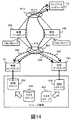
本実施例によれば、以上の課題を解決するためのテナントネットワークの構成方法が提供される。すなわち、図7に示した構成において、仮想インスタンスは仮想ゲートウェイを、物理インスタンスは物理ゲートウェイを経由するよう、レイヤ3の経路制御を行う方法である。本構成方法の概念図を図8に示す。
図8に示す通り、本実施例では仮想インスタンス24aと物理インスタンス14を相互に内部ネットワーク(LAN)300へ接続し、さらにゲートウェイを介して外部ネットワーク(WAN)302aへ接続し、クライアントコンピュータ70へサービスを提供する。このとき、仮想インスタンス24aと物理インスタンス14の相互通信808はレイヤ2で接続された同一サブネット内で行われるが、仮想インスタンス24aとの外部通信801は仮想ゲートウェイ24bを介して、物理インスタンス14との外部通信800は物理ゲートウェイ500を介して行われる。
それぞれのゲートウェイの設定には、DHCP(Dynamic Host Configuration Protocol)サーバ802を用いる。DHCPサアーバ802は、いずれかのゲートウェイのLAN300側に設置される。
仮想インスタンス24aが生成され、LAN300に接続してIPアドレス割り当て要求803をブロードキャストすると、DHCPサーバ802は、仮想インスタンス24a用のIPアドレスの払い出しとともに仮想ゲートウェイ24bのアドレス(図では192.168.11.1)をデフォルトゲートウェイとして応答する。According to the present embodiment, a tenant network configuration method for solving the above problems is provided. That is, in the configuration shown in FIG. 7, the
As shown in FIG. 8, in this embodiment, the
For setting each gateway, a DHCP (Dynamic Host Configuration Protocol)
When the
一方、物理インスタンス14が生成された際には、同様にIPアドレス割り当て要求807に対して物理ゲートウェイ500のアドレス(図では192.168.11.2)をデフォルトゲートウェイとして応答する。 On the other hand, when the
本実施例におけるDHCPサーバ802は、図9に示すネットワークアドレス管理テーブル815を有する。標準的なDHCPサーバの実装では、DHCPクライアント(本実施例では仮想インスタンスおよび物理インスタンス)をMACアドレスにより識別し、要求に応じてプール管理されたIPアドレスと、サブネットマスク、DNSサーバ、デフォルトゲートウェイを応答する。図9においても同様に、インスタンス815aに対してMACアドレス815d、割り当てるIPアドレス815eの組を管理している。本実施例においてはさらに、インスタンス種別815bに応じて、異なるゲートウェイ815fを指定する。これらの各ネットワーク設定情報は、当該インスタンスのOSにて、より正確にはネットワークインタフェース管理領域にて保持される。インスタンス種別815bとゲートウェイ815fの選別方法は後述する。
<処理フロー>
以下、管理コンピュータの構成と本実施例の処理フローについて説明する。The
<Processing flow>
The configuration of the management computer and the processing flow of this embodiment will be described below.
図10に管理コンピュータ200の管理プログラム203bの詳細な構成を示す。前述の統合サービス管理部204aはさらに、管理クライアント73bから要求を受け付けるユーザ要求管理部211、インスタンスの構成情報を管理するインスタンス管理テーブル212、インスタンスに導入するOSイメージを保持するOSイメージライブラリ213、システム内の装置群の構成を管理するエレメント管理部214、ゲートウェイの構成を管理するゲートウェイ管理部217、およびそれらを協調的に作用させるサービスオーケストレータ210から構成される。統合サービス管理部204aの下位に位置する各装置管理部(サーバ管理部204b、ネットワーク管理部204c、ストレージ管理部204d)は、主にエレメント管理部214のもとで制御される。エレメント管理部には、全ての装置構成を集約したエレメント管理テーブル群215、およびネットワークスイッチに設定するVLAN IDを集約した総合VLAN ID管理テーブル216を備える。 FIG. 10 shows a detailed configuration of the
図11に、本実施例においてインスタンス作成に伴ってテナントネットワークを構成する処理フローを示す。 FIG. 11 shows a processing flow for configuring a tenant network in accordance with instance creation in this embodiment.
ユーザが管理クライアント73bを用いてインスタンス作成要求を発信すると、統合サービス管理部204aのユーザ要求管理部211がユーザ権限を認証し、前述のインスタンスを作成する手順が開始される。装置構成は図12に示すエレメント管理テーブル群215において管理されている。エレメント管理テーブル群215は、装置管理部から複製された管理テーブル、例えばサーバ装置の構成を管理するサーバ管理テーブル820や、物理スイッチ管理テーブル821などから構成される。エレメント管理テーブル群215を調べることで、装置の使用状況や接続関係などの構成が把握できる。例えば、サーバ管理テーブル820のハイパバイザフィールド820bを調べることで、ハイパバイザが導入済みか否かを判別できる。さらに、エレメント管理テーブル群215には、装置を管理コンピュータに登録した際に生成される関連付け情報215aが含まれており、例えばどのサーバ820aのどのインタフェース820dが、どのスイッチ821aの物理ポート821cに接続されているか、を知ることができる。インスタンス作成時には、このエレメント管理テーブル群215をもとに各装置管理部からリソース空き容量を取得し、作成先装置の決定が行われる。 When the user sends an instance creation request using the
ステップ900において、前述のインスタンスを作成する手順を完了すると、ステップ901で一旦当該インスタンスをシャットダウンし、テナントネットワークの構成手順に移る。 In
ステップ902において、ユーザの要求に従い、VLAN IDを決定する。本実施例においてテナントとVLAN IDの対応付けは、総合VLAN ID管理テーブル216において管理されている。図13に当該テーブルの詳細を示す。ネットワーク管理部204cは、物理スイッチVLAN ID管理テーブル218、および仮想スイッチVLAN ID管理テーブル219の情報を不整合なく集約したものである。第一の実施例に示したように、仮想/物理スイッチについての管理テーブルのみをそれぞれ保持する方法もあるが、総合VLAN ID管理テーブルのように集約した管理テーブルを別に持つ方法によっても、VLANによる論理ネットワーク分割が適切に構成可能である。物理スイッチの管理情報がネットワーク管理部204cに保持される一方、仮想スイッチはハイパバイザが実装する一つの機能であり、その管理情報はサーバ管理部204bに保持される。ユーザが既存のテナントネットワークにインスタンスを追加する要求を実行している場合は、ユーザが指定した当該テナントID216aのVLAN ID216bを参照する。ユーザが新規にテナントネットワークの作成を要求している場合は、新たなテナントID216aとVLAN ID216bを確保し、総合VLAN ID管理テーブル216に追加する。 In
ステップ903において、ユーザの要求が物理インスタンスであるか、または仮想インスタンスであるかに応じて処理を分岐させる。
ユーザが物理インスタンスの追加を要求している場合、ステップ904において物理スイッチのVLAN設定を行う。より具体的には、物理スイッチVLAN ID管理テーブル218において、当該VLAN ID218eが設定可能か否か(他のIDと重複しないか、あるいは装置仕様上設定可能な範囲か)を判別し、当該物理サーバ(ホスト)ID218aに対応するポート属性218dをアクセスモード(ポートVLAN属性)に設定する。さらに、ステップ905において、当該インスタンスのゲートウェイを指定するゲートウェイ管理部217から、利用可能な物理ゲートウェイ情報を取得する。ここでゲートウェイ管理部217は、物理ゲートウェイ500を指定するために少なくとも当該ゲートウェイの内部ネットワーク側IPアドレスを保持する。物理的な接続関係を構築している適切な物理ゲートウェイが存在しない場合は処理を中止するか、物理インスタンスの作成方法と同様の方法により、新たに物理ゲートウェイを作成する。本実施例においては、さらにDHCPサーバに対して同物理ゲートウェイの設定を行う。より具体的には、ネットワークアドレス管理テーブル815において、作成したインスタンス情報と、その MACアドレス815d、およびゲートウェイのIPアドレスを登録する。
ユーザが仮想インスタンスの追加を要求している場合、ステップ906においてまず仮想スイッチのVLAN設定を行う。より具体的には、仮想スイッチVLAN ID管理テーブル219において、当該VLAN ID219bが設定可能か否かを判別し、当該テナントID219aおよびインスタンスID219cに対応させてVLAN ID219bを設定する。次に、ステップ907において、対応する物理スイッチVLAN ID管理テーブル218を編集する。より具体的には、物理スイッチVLAN ID管理テーブル218において、当該VLAN ID218eが設定可能か否かを判別し、当該仮想サーバホストID218aに対応するポート属性218dをトランクモード(タグVLAN属性)に設定する。さらに、ステップ905において、当該インスタンスのゲートウェイを指定するゲートウェイ管理部217から、利用可能な仮想ゲートウェイ情報を取得する。ここでゲートウェイ管理部217は、仮想ゲートウェイ24bを指定するために少なくとも当該ゲートウェイの内部ネットワーク側IPアドレスを保持する。物理的な接続関係を構築している適切な仮想ゲートウェイを作成しえない場合には処理を中止するか、仮想インスタンスの作成方法と同様の方法により、新たに仮想ゲートウェイを作成する。本実施例においては、さらにDHCPサーバに対して同仮想ゲートウェイの設定を行う。より具体的には、ネットワークアドレス管理テーブル815において、作成したインスタンス情報と、そのMACアドレス815d、およびゲートウェイのIPアドレスを登録する。In
If the user is requesting addition of a physical instance, the VLAN setting of the physical switch is performed in
If the user is requesting addition of a virtual instance, in
ステップ909においてインスタンスを再起動すると、当該インスタンスはDHCPサーバからネットワーク設定の割り当てを受けて稼働する。そのネットワーク設定は続くステップ910において、例えば同一テナントネットワーク内の他のインスタンスによるICMP受信により、疎通が確認される。 When the instance is restarted in
正常にインスタンスの追加が完了すると、ユーザ要求管理部211により、ユーザへ当該インスタンスの利用開始が通知される。このとき、インスタンスにアクセスするためのユーザアカウント情報や、ネットワークアドレスを合わせて通知してもよい。 When the addition of the instance is completed normally, the user
本実施例により、ユーザが要求するサービスレベルに応じて物理インスタンスおよび仮想インスタンスが追加された際に、テナントネットワークが構成される。さらに、性能安定が求められる物理インスタンスは性能安定な物理ゲートウェイを、リソース利用効率の高い仮想インスタンスは高効率な仮想ゲートウェイを利用して稼働する。すなわち、仮想/非仮想サーバ混在により計算処理リソースやストレージリソースの全体最適が実現されるとともに、仮想/物理ゲートウェイの使い分けによりネットワークリソースの全体最適も実現することができる。外部ネットワークとの通信における振り分け比率は、ユーザが要求するインスタンス種別に応じて静的に決定される。したがって、従来技術が提供する、通信負荷を監視して負荷分散方法を変化させる方式のように、適正な負荷分散が実現されるまでに長い時間を要することもなく、また複雑な機能の実装や処理コストも不要である。 According to this embodiment, a tenant network is configured when a physical instance and a virtual instance are added according to a service level requested by a user. Furthermore, a physical instance that requires stable performance operates using a physical gateway with stable performance, and a virtual instance with high resource utilization efficiency operates using a highly efficient virtual gateway. That is, the overall optimization of the calculation processing resources and the storage resources can be realized by mixing the virtual / non-virtual servers, and the overall optimization of the network resources can be realized by properly using the virtual / physical gateway. The distribution ratio in communication with the external network is statically determined according to the instance type requested by the user. Therefore, it does not take a long time to achieve proper load distribution, as in the conventional technology that monitors the communication load and changes the load distribution method. Processing costs are also unnecessary.
以上の説明では、インスタンスを作成する際にテナントネットワークを構成する例を対象としたが、本発明の対象はこれにとどまらない。例えば、新たにテナントネットワークのみを作成する場合や、仮想インスタンスと物理インスタンスを相互に移行する場合にも同様のシステム構成により本機能が実現される。 In the above description, the example of configuring a tenant network when creating an instance is targeted, but the subject of the present invention is not limited to this. For example, this function is realized by a similar system configuration when only a tenant network is newly created or when a virtual instance and a physical instance are migrated to each other.
また、本実施例においてはVLANとレイヤ3経路制御により上述のテナントネットワーク構成を実現したが、本発明の構成はこれらの技術に依存するものではない。したがって、例えばVXLANなど、レイヤ2通信をレイヤ3通信によりカプセル化してレイヤ2VLAN空間を延伸する技術を用いる場合においても、同様のシステム構成により本機能が実現される。 In the present embodiment, the tenant network configuration described above is realized by VLAN and
第一の実施例では、DHCPサーバを用いて仮想および物理ゲートウェイの使い分けを実現した。しかしながら、一般的な環境においては、障害時に備え静的アドレスを利用したいという要件から、DHCPサーバを利用しない運用も行われる。DHCPによるネットワーク設定によれば、効率的にIPアドレスのプール管理を行える一方、アドレスのリース期間が終わるごとにネットワーク設定の更新を行わなければならない。このとき、DHCPサーバに障害が発生しただけで、テナント内のインスタンスが通信不能に陥る危険性がある。 In the first embodiment, the use of virtual and physical gateways is realized using a DHCP server. However, in a general environment, an operation that does not use a DHCP server is also performed because of a requirement to use a static address in case of a failure. According to the network setting by DHCP, the IP address pool can be efficiently managed, but the network setting must be updated every time the lease period of the address ends. At this time, there is a risk that an instance in the tenant becomes incapable of communication only when a failure occurs in the DHCP server.
静的IPアドレスを利用する場合、管理ネットワークを経由して手動設定する方法があるが、手作業によるアドレス重複や利用状態管理の煩雑化のリスクが伴う。そこで、本実施例では、インスタンスを作成するもととなるマスタOSイメージ管理との連携により、DHCPに依存しないネットワーク設定方法を提供する。 When a static IP address is used, there is a method of manual setting via a management network, but there is a risk of manual address duplication and complicated usage status management. Therefore, in this embodiment, a network setting method that does not depend on DHCP is provided in cooperation with the master OS image management that is the basis for creating an instance.
図14に示すように、本実施例においては、DHCPサーバを利用しない点を除き、第一の実施例と同様のシステム構成を有する。特に、OSイメージライブラリ213において仮想/物理インスタンスの種別に応じてカスタマイズされたネットワーク設定を持つという特徴を有する。OSイメージライブラリ213に登録されるマスタイメージの実態は、ストレージ装置100内部に格納される。物理インスタンス14のマスタイメージ830はボリュームであり、物理インスタンス作成時にストレージ制御プログラム153bのコピー機能により起動用のディスクデバイス831が作成される。一方、仮想インスタンスのマスタイメージ832は仮想ディスクの形式をとり、ハイパバイザのコピー機能により起動用の仮想ディスク833が作成される。 As shown in FIG. 14, this embodiment has the same system configuration as that of the first embodiment, except that a DHCP server is not used. In particular, the
本実施例では、ゲートウェイ管理部217において、ネットワークアドレス管理テーブル815を持ち、仮想/物理インスタンスの種別により対応するネットワーク設定をマスタイメージに含める。より具体的には、ネットワーク設定をカスタマイズしたOSイメージを使ってマスタイメージを作成する、あるいは図11ステップ909においてインスタンスを再起動した際に当該ネットワーク設定が読み込まれるようOS初期化ファイルを構成しておく。 In this embodiment, the
本実施例によれば、作成されるインスタンスに対して静的にIPアドレスが付与され、仮想/非仮想サーバの種別に応じて仮想/物理ゲートウェイが静的に設定される。このネットワーク設定を実施するとき、ネットワークを疎通させる必要はなく、またDHCPサーバを設置する必要も生じない。さらに、DHCPサーバなどネットワークアドレスの集中管理を行う装置に障害が生じた場合でも、当該インスタンスとクライアントコンピュータとのの接続性、および同一テナントに接続されたインスタンス間の接続性が保持される。加えて、ストレージ装置100の高速なコピー機能を活用することで、ネットワークインストールのように通信帯域に負荷をかけることがないという利点を有する。 According to this embodiment, an IP address is statically assigned to a created instance, and a virtual / physical gateway is statically set according to the type of virtual / non-virtual server. When performing this network setting, it is not necessary to communicate with the network, and it is not necessary to install a DHCP server. Furthermore, even when a device such as a DHCP server that performs centralized management of network addresses fails, the connectivity between the instance and the client computer and the connectivity between instances connected to the same tenant are maintained. In addition, by utilizing the high-speed copy function of the
本実施例によれば、外部ネットワークから内部ネットワークへのアクセスについて、仮想/物理インスタンスを考慮して振り分ける機能が提供される。前述の実施例では、おもに内部ネットワークから外部ネットワークへのアクセスについて、インスタンスの種別に応じたゲートウェイを経由させる方法について述べた。一方で、クライアントコンピュータ70側からのアクセス要求についても、物理インスタンスと仮想インスタンスの特性に応じてゲートウェイに振り分けたい。
本発明が対象とするような仮想/非仮想混在環境では、ユーザが求める性能要件が、物理インスタンスと仮想インスタンスの数などとして現れる。したがって、予測のできないアクセス要求の変動に対応するために複雑な監視機能と負荷分散機能を実装するよりも、まずテナント内の仮想/物理インスタンスの規模に応じて静的にゲートウェイを指定する方法で、より簡潔かつ効果的な性能改善が実現できると考えられる。According to the present embodiment, a function of distributing access from an external network to an internal network in consideration of virtual / physical instances is provided. In the above-described embodiment, the method of passing the gateway according to the type of the instance mainly for the access from the internal network to the external network has been described. On the other hand, an access request from the
In a virtual / non-virtual mixed environment as the object of the present invention, the performance requirement required by the user appears as the number of physical instances and virtual instances. Therefore, rather than implementing complex monitoring functions and load balancing functions to cope with unpredictable changes in access requests, the gateway is first statically specified according to the size of virtual / physical instances in the tenant. Therefore, it is considered that more concise and effective performance improvement can be realized.
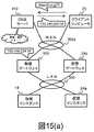
本実施例において、外部ネットワークからのアクセスを物理ゲートウェイおよび仮想ゲートウェイに振り分ける構成を図15(a)および(b)の二通りを考える。 In the present embodiment, two configurations shown in FIGS. 15A and 15B are considered as configurations for distributing access from an external network to a physical gateway and a virtual gateway.
第一の方法は、DNSを利用する方法である。クライアントコンピュータ70がDNSサーバ810に問い合わせ、アクセス先ドメイン名をIPアドレスへ解決する場合を考える。このとき、物理ゲートウェイ(または物理インスタンス)のIPアドレスを宛先として通知するか、仮想ゲートウェイ(または仮想インスタンス)のIPアドレスを通知するか、の割合をDNSサーバの設定により調整する。より具体的には、仮想および物理ゲートウェイまたはインスタンスの性能比をある一定値で評価し、応答するIPアドレスの発生確率とする。
第二の方法はゲートウェイの手前にロードバランサ811を配置する方法である。一般的なロードバランサにおける負荷分散アルゴリズムとして、物理ゲートウェイ(または物理インスタンス)を宛先とするか、仮想ゲートウェイ(または仮想インスタンス)を宛先とするか、の割合をゲートウェイまたはインスタンスの性能比と比例させる。プロキシとして動作させるか、またはNATにより透過的なアクセスを提供する。The first method is a method using DNS. Consider a case where the
The second method is a method of placing a
本実施例によれば、外部ネットワークからのアクセスを物理ゲートウェイと仮想ゲートウェイとに振り分けられる。外部アクセスの振り分け比率は、ユーザが要求するインスタンス種別に応じて静的に決定される。したがって、従来技術が提供する、通信負荷を監視して負荷分散方法を変化させる方式のように、クライアント要求の適正な負荷分散が実現されるまでに長い時間を要することもなく、また複雑な機能の実装や処理コストも不要である。 According to the present embodiment, access from an external network can be distributed to a physical gateway and a virtual gateway. The external access distribution ratio is statically determined according to the instance type requested by the user. Therefore, it does not take a long time to achieve proper load distribution of client requests, as in the conventional technology that changes the load distribution method by monitoring the communication load. Implementation costs and processing costs are also unnecessary.
10…第一の物理サーバ、11…CPU、12…メモリ、13a…オペレーティングシステム、13b…アプリケーションプログラム、14…物理インスタンス、15…ファイバチャネルインタフェース、16…イーサネットインタフェース、20…第二の物理サーバ、23b…仮想化プログラム、24a…仮想インスタンス、24b…仮想ゲートウェイ、27…仮想ネットワークスイッチ、50…ファイバチャネルスイッチ、 51…ストレージエリアネットワーク、60…物理ネットワークスイッチ、61…内部イーサネットワーク、70…クライアントコンピュータ
73a…サービスクライアント、73b…管理クライアント、100…ストレージ装置、150…ストレージ制御部、153a…応答プログラム、153b…ストレージ制御プログラム、154…キャッシュ、200…管理コンピュータ、203b…管理プログラム、204a…統合サービス管理部、204b…サーバ装置管理部
204c…ネットワーク装置管理部、204d…ストレージ装置管理部、300…内部ネットワーク、301…管理ネットワーク、302…外部ネットワーク、500…物理ゲートウェイ、802…DHCPサーバDESCRIPTION OF
Claims (15)
Translated fromJapanese物理インスタンスが動作する第2の物理サーバと、
前記第1の物理サーバと前記第2の物理サーバと接続され、当該前記第1の物理サーバおよび前記第2の物理サーバ間のネットワークを制御する物理スイッチと、
に接続される管理コンピュータであって、
前記複数の仮想インスタンスのそれぞれについて、当該仮想インスタンスが接続する内部ネットワークとの対応関係を示す仮想スイッチ管理情報と、
前記物理インスタンスと、当該物理インスタンスが接続する内部ネットワークとの対応関係を示す物理スイッチ管理情報と、
前記第1の物理サーバと、前記第2の物理サーバと、前記物理スイッチの構成を管理する統合管理部を備え、
前記統合管理部は、
前記物理インスタンスと同じ内部ネットワークに接続する第1の仮想インスタンスを作成するための第1のインスタンス作成要求を受信すると、
前記第1の物理サーバ上に前記第1の仮想インスタンスを作成し、
前記物理スイッチ管理情報を参照して、前記物理インスタンスが接続する第1の内部ネットワークを特定し、
前記第1の仮想インスタンスが前記第1の内部ネットワークに接続されるように前記仮想スイッチと前記物理スイッチを設定する
ことを特徴とする管理コンピュータ。A first physical server on which a virtual switch that controls a plurality of virtual instances and a network between the virtual instances operates;
A second physical server running the physical instance, and
A physical switch connected to the first physical server and the second physical server and controlling a network between the first physical server and the second physical server;
A management computer connected to the
For each of the plurality of virtual instances, virtual switch management information indicating a correspondence relationship with the internal network to which the virtual instance is connected;
Physical switch management information indicating the correspondence between the physical instance and the internal network to which the physical instance is connected;
An integrated management unit for managing configurations of the first physical server, the second physical server, and the physical switch;
The integrated management unit
When receiving a first instance creation request to create a first virtual instance connected to the same internal network as the physical instance,
Creating the first virtual instance on the first physical server;
Referring to the physical switch management information, identify the first internal network to which the physical instance is connected,
A management computer configured to set the virtual switch and the physical switch so that the first virtual instance is connected to the first internal network.
前記第1の物理サーバは、当該第1の物理サーバの物理リソースを論理的に分割して複数の仮想マシンとして管理する仮想化機能を有し、前記複数の仮想インスタンスの各々は前記複数の仮想マシンのいずれかで動作する
ことを特徴とする管理コンピュータ。The management computer according to claim 1,
Thefirst physical server has a virtualization function that logically divides the physical resourcesof thefirst physical server and manages them as a plurality of virtual machines, and each of the plurality of virtual instances includes the plurality of virtual machines. A management computer that operates on any of the machines.
前記統合管理部は、前記複数の仮想インスタンスのうちの第2の仮想インスタンスと同じ内部ネットワークに接続する第1の物理インスタンスを作成するための第2インスタンス作成要求を受信すると、
前記物理スイッチに接続される第3の物理サーバ上に前記第1の物理インスタンスを作成し、
前記仮想スイッチ管理情報を参照して、前記第2の仮想インスタンスが接続する第2の内部ネットワークを特定し、
前記第1の物理インスタンスが前記第2の内部ネットワークに接続されるように前記物理スイッチを設定する
ことを特徴とする管理コンピュータ。The management computer according to claim1 ,
When the integrated management unit receives a second instance creation request for creating a first physical instance connected to the same internal network as the second virtual instance of the plurality of virtual instances,
Creating the first physical instance on a third physical server connected to the physical switch;
With reference to the virtual switch management information, a second internal network to which the second virtual instance is connected is identified,
A management computer configured to set the physical switch so that the first physical instance is connected to the second internal network.
前記第2の物理サーバは、前記仮想スイッチと前記物理スイッチの制御によって前記第1の内部ネットワークおよび外部ネットワークに接続されている仮想ゲートウェイを有し、
前記管理コンピュータは、前記物理スイッチの制御によって前記第1の内部ネットワークおよび前記外部ネットワークに接続されている物理ゲートウェイと、さらに接続されており、
前記第1のインスタンス作成要求に応じて、
前記第1の仮想インスタンスが前記仮想ゲートウェイを経由して前記第1の内部ネットワークから前記外部ネットワークに接続するように、前記第1の仮想インスタンスを設定し、
前記第1の仮想インスタンスの設定は、
前記第1のインスタンス作成要求元のテナントに対応付けられた前記内部ネットワークを特定し、当該特定された内部ネットワークを前記仮想スイッチ管理情報に設定することで行われる
ことを特徴とする管理コンピュータ。The management computer according to claim1 ,
The second physical server has a virtual gateway connected to the first internal network and an external network by the control of the virtual switch and the physical switch,
The management computer is further connected to a physical gateway connected to the first internal network and the external network under the control of the physical switch;
In response to the first instance creation request,
Configuring the first virtual instance such that the first virtual instance connects from the first internal network to the external network via the virtual gateway;
The setting of the first virtual instance is
It is performed by specifying the internal network associated with the tenant that is the first instance creation request source, and setting the specified internal network in the virtual switch management information. Management computer.
前記物理インスタンスが前記物理ゲートウェイを経由して前記第1の内部ネットワークから前記第2のネットワークに接続するように、前記物理インスタンスを設定する
ことを特徴とする管理コンピュータ。The management computer according to claim 4,
A management computer configured to set the physical instance so that the physical instance connects to the second network from the first internal network via the physical gateway.
前記物理ゲートウェイのネットワークアドレス情報と、
前記仮想ゲートウェイのネットワークアドレス情報と、管理し、
DHCP(Dynamic Host Configuration Protocol)サーバを介して、当該ネットワークアドレス情報を前記物理インスタンス、前記第1の仮想インスタンスに通知することで、前記第1の仮想インスタンスが前記仮想ゲートウェイを経由して前記第1の内部ネットワークから前記外部ネットワークに接続するように、前記第1の仮想インスタンスを設定する
ことを特徴とする管理コンピュータ。The management computer according to claim 5,
Network address information of the physical gateway;
Managing the network address information of the virtual gateway,
By notifying the physical instance and the first virtual instance of the network address information via a DHCP (Dynamic Host Configuration Protocol) server, the first virtual instance passes the first virtual instance via the virtual gateway. The first virtual instance is set so as to connect to the external network from the internal network of the management computer.
前記物理ゲートウェイのネットワークアドレス情報と、
前記仮想ゲートウェイのネットワークアドレス情報と、管理し、
前記第1の物理サーバおよび前記第2の物理サーバに接続されるストレージ装置と更に接続され、
前記第1の仮想インスタンスによって読み込まれるOS(Operation system)のマスタイメージとともに前記仮想ゲートウェイのアドレス情報を格納することで、前記第1の仮想インスタンスが前記仮想ゲートウェイを経由して前記第1の内部ネットワークから前記外部ネットワークに接続するように、前記第1の仮想インスタンスを設定する
ことを特徴とする管理コンピュータ。The management computer according to claim 5,
Network address information of the physical gateway;
Managing the network address information of the virtual gateway,
It is further connected to a storage device connected to the first physical server and the second physical server,
By storing the address information of the virtual gateway together with a master image of an OS (Operation system) read by the first virtual instance, the first virtual instance passes through the virtual gateway to the first internal network. The management computer is configured to set the first virtual instance to connect to the external network.
に接続される管理コンピュータによるネットワーク構成方法であって、
前記複数の仮想インスタンスのそれぞれについて、当該仮想インスタンスが接続する内部ネットワークとの対応関係を示す仮想スイッチ管理情報を管理し、
さらに、前記物理インスタンスと、当該物理インスタンスが接続する内部ネットワークとの対応関係を示す物理スイッチ管理情報を管理し、
前記物理インスタンスと同じ内部ネットワークに接続する第1の仮想インスタンスを作成するための第1のインスタンス作成要求を受信すると、
前記第1の物理サーバ上に前記第1の仮想インスタンスを作成し、
前記物理スイッチ管理情報を参照して、前記物理インスタンスが接続する第1の内部ネットワークを特定し、
前記第1の仮想インスタンスが前記第1の内部ネットワークに接続されるように前記仮想スイッチと前記物理スイッチを設定する
ことを特徴とするネットワーク構成方法。A first physical server on which a virtual switch that controls a plurality of virtual instances and a network between the virtual instances operates, a second physical server on which the physical instances operate, the first physical server, and the second physical server A physical switch connected to a server and controlling a network between the first physical server and the second physical server;
A network configuration method by a management computer connected to
For each of the plurality of virtual instances, manage virtual switch management information indicating a correspondence relationship with the internal network to which the virtual instance is connected,
Furthermore, managing physical switch management information indicating the correspondence between the physical instance and the internal network to which the physical instance is connected,
When receiving a first instance creation request to create a first virtual instance connected to the same internal network as the physical instance,
Creating the first virtual instance on the first physical server;
Referring to the physical switch management information, identify the first internal network to which the physical instance is connected,
A network configuration method comprising: setting the virtual switch and the physical switch so that the first virtual instance is connected to the first internal network.
前記第1の物理サーバは、当該第1の物理サーバの物理リソースを論理的に分割して複数の仮想マシンとして管理する仮想化機能を有し、前記複数の仮想インスタンスの各々は前記複数の仮想マシンのいずれかで動作する
ことを特徴とするネットワーク構成方法。The network configuration method according to claim 8, comprising:
Thefirst physical server has a virtualization function that logically divides the physical resourcesof thefirst physical server and manages them as a plurality of virtual machines, and each of the plurality of virtual instances includes the plurality of virtual machines. A network configuration method characterized by operating on any of the machines.
前記複数の仮想インスタンスのうちの第2の仮想インスタンスと同じ内部ネットワークに接続する第1の物理インスタンスを作成するための第2インスタンス作成要求を受信すると、
前記物理スイッチに接続される第3の物理サーバ上に前記第1の物理インスタンスを作成し、
前記仮想スイッチ管理情報を参照して、前記第2の仮想インスタンスが接続する第2の内部ネットワークを特定し、
前記第1の物理インスタンスが前記第2の内部ネットワークに接続されるように前記物理スイッチを設定する
ことを特徴とするネットワーク構成方法。The network configuration method according to claim8 , comprising:
When receiving a second instance creation request for creating a first physical instance connected to the same internal network as a second virtual instance of the plurality of virtual instances,
Creating the first physical instance on a third physical server connected to the physical switch;
With reference to the virtual switch management information, a second internal network to which the second virtual instance is connected is identified,
A network configuration method, wherein the physical switch is set so that the first physical instance is connected to the second internal network.
前記第2の物理サーバは、前記仮想スイッチと前記物理スイッチの制御によって前記第1の内部ネットワークおよび外部ネットワークに接続されている仮想ゲートウェイを有し、
前記管理コンピュータは、前記物理スイッチの制御によって前記第1の内部ネットワークおよび前記外部ネットワークに接続されている物理ゲートウェイと、さらに接続されており、
前記第1のインスタンス作成要求に応じて、
前記第1の仮想インスタンスが前記仮想ゲートウェイを経由して前記第1の内部ネットワークから前記外部ネットワークに接続するように、前記第1の仮想インスタンスを設定し、
前記第1の仮想インスタンスの設定は、
前記第1のインスタンス作成要求元のテナントに対応付けられた前記内部ネットワークを特定し、当該特定された内部ネットワークを前記仮想スイッチ管理情報に設定することで行われる
ことを特徴とするネットワーク構成方法。The network configuration method according to claim8 , comprising:
The second physical server has a virtual gateway connected to the first internal network and an external network by the control of the virtual switch and the physical switch,
The management computer is further connected to a physical gateway connected to the first internal network and the external network under the control of the physical switch;
In response to the first instance creation request,
Configuring the first virtual instance such that the first virtual instance connects from the first internal network to the external network via the virtual gateway;
The setting of the first virtual instance is
It is performed by specifying the internal network associated with the tenant that is the first instance creation request source, and setting the specified internal network in the virtual switch management information. Network configuration method.
前記物理インスタンスが前記物理ゲートウェイを経由して前記第1の内部ネットワークから前記第2のネットワークに接続するように、前記物理インスタンスを設定する
ことを特徴とするネットワーク構成方法。The network configuration method according to claim 11, comprising:
A network configuration method, wherein the physical instance is set so that the physical instance is connected to the second network from the first internal network via the physical gateway.
前記物理ゲートウェイのネットワークアドレス情報と、
前記仮想ゲートウェイのネットワークアドレス情報と、管理し、
DHCP(Dynamic Host Configuration Protocol)サーバを介して、当該ネットワークアドレス情報を前記物理インスタンス、前記第1の仮想インスタンスに通知することで、前記第1の仮想インスタンスが前記仮想ゲートウェイを経由して前記第1の内部ネットワークから前記外部ネットワークに接続するように、前記第1の仮想インスタンスを設定する
ことを特徴とするネットワーク構成方法。Thenetwork configuration method according to claim 11,comprising:
Network address information of the physical gateway;
Managing the network address information of the virtual gateway,
By notifying the physical instance and the first virtual instance of the network address information via a DHCP (Dynamic Host Configuration Protocol) server, the first virtual instance passes the first virtual instance via the virtual gateway. A network configuration method, wherein the first virtual instance is set so as to connect to the external network from the internal network.
前記管理コンピュータは、第1の物理サーバおよび前記第2の物理サーバに接続されるストレージ装置と更に接続され、
前記物理ゲートウェイのネットワークアドレス情報と、前記仮想ゲートウェイのネットワークアドレス情報と、を管理し、
前記第1の仮想インスタンスによって読み込まれるOS(Operation system)のマスタイメージとともに前記仮想ゲートウェイのアドレス情報を格納することで、前記第1の仮想インスタンスが前記仮想ゲートウェイを経由して前記第1の内部ネットワークから前記外部ネットワークに接続するように、前記第1の仮想インスタンスを設定する
ことを特徴とするネットワーク構成方法。A network configuration method according to claim 12, comprising:
The management computer is further connected to a storage device connected to the first physical server and the second physical server;
Managing network address information of the physical gateway and network address information of the virtual gateway;
By storing the address information of the virtual gateway together with a master image of an OS (Operation system) read by the first virtual instance, the first virtual instance passes through the virtual gateway to the first internal network. Anetwork configuration method comprising: setting the first virtual instance so as to be connected to the external network.
前記外部ネットワークに接続されるクライアントが前記物理ゲートウェイもしくは前記仮想ゲートウェイを経由して前記第1の内部ネットワークに接続する前記仮想インスタンスもしくは前記物理インスタンスにアクセスについて、
前記第1の内部ネットワークに接続する前記物理インスタンスの数と前記仮想インスタンスの数の比率に基づき、前記物理ゲートウェイもしくは前記仮想ゲートウェイのいずれを経由するかを設定する
ことを特徴とするネットワーク構成方法。The network configuration method according to claim 13,
A client connected to the external network accesses the virtual instance or the physical instance connected to the first internal network via the physical gateway or the virtual gateway.
A network configuration method comprising: setting which of the physical gateway or the virtual gateway is to be routed based on a ratio between the number of the physical instances connected to the first internal network and the number of the virtual instances.
Applications Claiming Priority (1)
| Application Number | Priority Date | Filing Date | Title |
|---|---|---|---|
| PCT/JP2013/054655WO2014128948A1 (en) | 2013-02-25 | 2013-02-25 | Virtual server and method for mana ging tenant network configuration in non-virtual server coexisting environment |
Publications (2)
| Publication Number | Publication Date |
|---|---|
| JP5953421B2true JP5953421B2 (en) | 2016-07-20 |
| JPWO2014128948A1 JPWO2014128948A1 (en) | 2017-02-02 |
Family
ID=51390771
Family Applications (1)
| Application Number | Title | Priority Date | Filing Date |
|---|---|---|---|
| JP2015501211AExpired - Fee RelatedJP5953421B2 (en) | 2013-02-25 | 2013-02-25 | Management method of tenant network configuration in virtual server and non-virtual server mixed environment |
Country Status (3)
| Country | Link |
|---|---|
| US (1) | US9575798B2 (en) |
| JP (1) | JP5953421B2 (en) |
| WO (1) | WO2014128948A1 (en) |
Families Citing this family (162)
| Publication number | Priority date | Publication date | Assignee | Title |
|---|---|---|---|---|
| JP6020273B2 (en)* | 2013-03-19 | 2016-11-02 | 富士通株式会社 | Monitoring device, information processing system, monitoring method, and monitoring program |
| WO2014188478A1 (en)* | 2013-05-20 | 2014-11-27 | 株式会社日立製作所 | Method for controlling items to be monitored in cloud system in which virtual environment and non-virtual environment intermingle, and management computer and computer system |
| US10749711B2 (en) | 2013-07-10 | 2020-08-18 | Nicira, Inc. | Network-link method useful for a last-mile connectivity in an edge-gateway multipath system |
| US10454714B2 (en) | 2013-07-10 | 2019-10-22 | Nicira, Inc. | Method and system of overlay flow control |
| US9887960B2 (en) | 2013-08-14 | 2018-02-06 | Nicira, Inc. | Providing services for logical networks |
| US10614047B1 (en)* | 2013-09-24 | 2020-04-07 | EMC IP Holding Company LLC | Proxy-based backup and restore of hyper-V cluster shared volumes (CSV) |
| WO2015048921A1 (en)* | 2013-10-02 | 2015-04-09 | Telefonaktiebolaget L M Ericsson(Publ) | A movable gateway, a dhcp server and respective methods performed thereby for enabling the gateway to move from a first access point to a second access point |
| US10200239B2 (en)* | 2013-12-27 | 2019-02-05 | Red Hat Israel, Ltd. | Normalized management network |
| US9602308B2 (en)* | 2014-06-23 | 2017-03-21 | International Business Machines Corporation | Servicing packets in a virtual network and a software-defined network (SDN) |
| US9600312B2 (en) | 2014-09-30 | 2017-03-21 | Amazon Technologies, Inc. | Threading as a service |
| US9830193B1 (en) | 2014-09-30 | 2017-11-28 | Amazon Technologies, Inc. | Automatic management of low latency computational capacity |
| US9715402B2 (en) | 2014-09-30 | 2017-07-25 | Amazon Technologies, Inc. | Dynamic code deployment and versioning |
| US9323556B2 (en) | 2014-09-30 | 2016-04-26 | Amazon Technologies, Inc. | Programmatic event detection and message generation for requests to execute program code |
| US9146764B1 (en) | 2014-09-30 | 2015-09-29 | Amazon Technologies, Inc. | Processing event messages for user requests to execute program code |
| US10048974B1 (en) | 2014-09-30 | 2018-08-14 | Amazon Technologies, Inc. | Message-based computation request scheduling |
| US9678773B1 (en) | 2014-09-30 | 2017-06-13 | Amazon Technologies, Inc. | Low latency computational capacity provisioning |
| US9413626B2 (en) | 2014-12-05 | 2016-08-09 | Amazon Technologies, Inc. | Automatic management of resource sizing |
| JP6467906B2 (en)* | 2014-12-19 | 2019-02-13 | 富士通株式会社 | Information processing system, information processing method, information processing program, and information processing apparatus |
| JP2016134721A (en)* | 2015-01-19 | 2016-07-25 | 富士通株式会社 | Information processing system, control method of information processing system and control program of management device |
| US10341188B2 (en)* | 2015-01-27 | 2019-07-02 | Huawei Technologies Co., Ltd. | Network virtualization for network infrastructure |
| US9588790B1 (en) | 2015-02-04 | 2017-03-07 | Amazon Technologies, Inc. | Stateful virtual compute system |
| US9733967B2 (en) | 2015-02-04 | 2017-08-15 | Amazon Technologies, Inc. | Security protocols for low latency execution of program code |
| WO2016146494A1 (en)* | 2015-03-13 | 2016-09-22 | Koninklijke Kpn N.V. | Method and control system for controlling provisioning of a service in a network |
| US9785476B2 (en) | 2015-04-08 | 2017-10-10 | Amazon Technologies, Inc. | Endpoint management system and virtual compute system |
| US9930103B2 (en) | 2015-04-08 | 2018-03-27 | Amazon Technologies, Inc. | Endpoint management system providing an application programming interface proxy service |
| US10425382B2 (en) | 2015-04-13 | 2019-09-24 | Nicira, Inc. | Method and system of a cloud-based multipath routing protocol |
| US10498652B2 (en) | 2015-04-13 | 2019-12-03 | Nicira, Inc. | Method and system of application-aware routing with crowdsourcing |
| US10135789B2 (en) | 2015-04-13 | 2018-11-20 | Nicira, Inc. | Method and system of establishing a virtual private network in a cloud service for branch networking |
| US10419365B2 (en)* | 2015-04-20 | 2019-09-17 | Hillstone Networks Corp. | Service insertion in basic virtual network environment |
| US20170063627A1 (en)* | 2015-08-25 | 2017-03-02 | Bluedata Software, Inc. | Allocation of virtual clusters in a large-scale processing environment |
| US9811434B1 (en) | 2015-12-16 | 2017-11-07 | Amazon Technologies, Inc. | Predictive management of on-demand code execution |
| US10754701B1 (en) | 2015-12-16 | 2020-08-25 | Amazon Technologies, Inc. | Executing user-defined code in response to determining that resources expected to be utilized comply with resource restrictions |
| US10067801B1 (en) | 2015-12-21 | 2018-09-04 | Amazon Technologies, Inc. | Acquisition and maintenance of compute capacity |
| US9910713B2 (en) | 2015-12-21 | 2018-03-06 | Amazon Technologies, Inc. | Code execution request routing |
| WO2017154163A1 (en)* | 2016-03-10 | 2017-09-14 | 株式会社日立製作所 | Computer system, gateway device control method and storage medium |
| JP2017167744A (en)* | 2016-03-15 | 2017-09-21 | 富士通株式会社 | Information processor, information processing system, program and information processing method |
| US9990222B2 (en) | 2016-03-18 | 2018-06-05 | Airwatch Llc | Enforcing compliance rules against hypervisor and virtual machine using host management component |
| US10594046B2 (en)* | 2016-03-29 | 2020-03-17 | Space Systems/Loral, Llc | Satellite system with single polarization path |
| US10891145B2 (en) | 2016-03-30 | 2021-01-12 | Amazon Technologies, Inc. | Processing pre-existing data sets at an on demand code execution environment |
| US11132213B1 (en) | 2016-03-30 | 2021-09-28 | Amazon Technologies, Inc. | Dependency-based process of pre-existing data sets at an on demand code execution environment |
| US10841273B2 (en)* | 2016-04-29 | 2020-11-17 | Nicira, Inc. | Implementing logical DHCP servers in logical networks |
| US10282229B2 (en) | 2016-06-28 | 2019-05-07 | Amazon Technologies, Inc. | Asynchronous task management in an on-demand network code execution environment |
| US10102040B2 (en) | 2016-06-29 | 2018-10-16 | Amazon Technologies, Inc | Adjusting variable limit on concurrent code executions |
| US10277708B2 (en) | 2016-06-30 | 2019-04-30 | Amazon Technologies, Inc. | On-demand network code execution with cross-account aliases |
| US10884787B1 (en) | 2016-09-23 | 2021-01-05 | Amazon Technologies, Inc. | Execution guarantees in an on-demand network code execution system |
| US10061613B1 (en) | 2016-09-23 | 2018-08-28 | Amazon Technologies, Inc. | Idempotent task execution in on-demand network code execution systems |
| US11119813B1 (en) | 2016-09-30 | 2021-09-14 | Amazon Technologies, Inc. | Mapreduce implementation using an on-demand network code execution system |
| US10348813B2 (en) | 2016-10-28 | 2019-07-09 | International Business Machines Corporation | Provisioning a bare-metal server |
| US11706127B2 (en) | 2017-01-31 | 2023-07-18 | Vmware, Inc. | High performance software-defined core network |
| US10992568B2 (en) | 2017-01-31 | 2021-04-27 | Vmware, Inc. | High performance software-defined core network |
| US20180219765A1 (en) | 2017-01-31 | 2018-08-02 | Waltz Networks | Method and Apparatus for Network Traffic Control Optimization |
| US20200036624A1 (en)* | 2017-01-31 | 2020-01-30 | The Mode Group | High performance software-defined core network |
| US10778528B2 (en) | 2017-02-11 | 2020-09-15 | Nicira, Inc. | Method and system of connecting to a multipath hub in a cluster |
| KR102259679B1 (en)* | 2017-03-19 | 2021-06-01 | 후아웨이 테크놀러지 컴퍼니 리미티드 | Network slice management method, unit and system |
| US10523539B2 (en) | 2017-06-22 | 2019-12-31 | Nicira, Inc. | Method and system of resiliency in cloud-delivered SD-WAN |
| JP2019029946A (en)* | 2017-08-03 | 2019-02-21 | 富士通株式会社 | COMMUNICATION CONTROL DEVICE, COMMUNICATION CONTROL SYSTEM, AND COMMUNICATION CONTROL METHOD |
| US11115480B2 (en) | 2017-10-02 | 2021-09-07 | Vmware, Inc. | Layer four optimization for a virtual network defined over public cloud |
| US10999100B2 (en) | 2017-10-02 | 2021-05-04 | Vmware, Inc. | Identifying multiple nodes in a virtual network defined over a set of public clouds to connect to an external SAAS provider |
| US10841131B2 (en) | 2017-10-02 | 2020-11-17 | Vmware, Inc. | Distributed WAN security gateway |
| US11223514B2 (en) | 2017-11-09 | 2022-01-11 | Nicira, Inc. | Method and system of a dynamic high-availability mode based on current wide area network connectivity |
| US10564946B1 (en) | 2017-12-13 | 2020-02-18 | Amazon Technologies, Inc. | Dependency handling in an on-demand network code execution system |
| US10733085B1 (en) | 2018-02-05 | 2020-08-04 | Amazon Technologies, Inc. | Detecting impedance mismatches due to cross-service calls |
| US10353678B1 (en) | 2018-02-05 | 2019-07-16 | Amazon Technologies, Inc. | Detecting code characteristic alterations due to cross-service calls |
| US10831898B1 (en) | 2018-02-05 | 2020-11-10 | Amazon Technologies, Inc. | Detecting privilege escalations in code including cross-service calls |
| US10725752B1 (en) | 2018-02-13 | 2020-07-28 | Amazon Technologies, Inc. | Dependency handling in an on-demand network code execution system |
| US10776091B1 (en) | 2018-02-26 | 2020-09-15 | Amazon Technologies, Inc. | Logging endpoint in an on-demand code execution system |
| US10853115B2 (en) | 2018-06-25 | 2020-12-01 | Amazon Technologies, Inc. | Execution of auxiliary functions in an on-demand network code execution system |
| US10649749B1 (en) | 2018-06-26 | 2020-05-12 | Amazon Technologies, Inc. | Cross-environment application of tracing information for improved code execution |
| US11146569B1 (en) | 2018-06-28 | 2021-10-12 | Amazon Technologies, Inc. | Escalation-resistant secure network services using request-scoped authentication information |
| US10949237B2 (en) | 2018-06-29 | 2021-03-16 | Amazon Technologies, Inc. | Operating system customization in an on-demand network code execution system |
| US11099870B1 (en) | 2018-07-25 | 2021-08-24 | Amazon Technologies, Inc. | Reducing execution times in an on-demand network code execution system using saved machine states |
| US11099917B2 (en) | 2018-09-27 | 2021-08-24 | Amazon Technologies, Inc. | Efficient state maintenance for execution environments in an on-demand code execution system |
| US11243953B2 (en) | 2018-09-27 | 2022-02-08 | Amazon Technologies, Inc. | Mapreduce implementation in an on-demand network code execution system and stream data processing system |
| US20200106669A1 (en)* | 2018-09-27 | 2020-04-02 | Nutanix, Inc. | Computing node clusters supporting network segmentation |
| CN109412951B (en) | 2018-10-12 | 2021-06-22 | 华为技术有限公司 | Method and device for sending routing information |
| US11943093B1 (en) | 2018-11-20 | 2024-03-26 | Amazon Technologies, Inc. | Network connection recovery after virtual machine transition in an on-demand network code execution system |
| US10884812B2 (en) | 2018-12-13 | 2021-01-05 | Amazon Technologies, Inc. | Performance-based hardware emulation in an on-demand network code execution system |
| US11176002B2 (en) | 2018-12-18 | 2021-11-16 | Storage Engine, Inc. | Methods, apparatuses and systems for cloud-based disaster recovery |
| US10958720B2 (en) | 2018-12-18 | 2021-03-23 | Storage Engine, Inc. | Methods, apparatuses and systems for cloud based disaster recovery |
| US11178221B2 (en) | 2018-12-18 | 2021-11-16 | Storage Engine, Inc. | Methods, apparatuses and systems for cloud-based disaster recovery |
| US11252019B2 (en) | 2018-12-18 | 2022-02-15 | Storage Engine, Inc. | Methods, apparatuses and systems for cloud-based disaster recovery |
| US10983886B2 (en) | 2018-12-18 | 2021-04-20 | Storage Engine, Inc. | Methods, apparatuses and systems for cloud-based disaster recovery |
| US10887382B2 (en) | 2018-12-18 | 2021-01-05 | Storage Engine, Inc. | Methods, apparatuses and systems for cloud-based disaster recovery |
| US11489730B2 (en) | 2018-12-18 | 2022-11-01 | Storage Engine, Inc. | Methods, apparatuses and systems for configuring a network environment for a server |
| US11240160B2 (en)* | 2018-12-28 | 2022-02-01 | Alibaba Group Holding Limited | Method, apparatus, and computer-readable storage medium for network control |
| US11010188B1 (en) | 2019-02-05 | 2021-05-18 | Amazon Technologies, Inc. | Simulated data object storage using on-demand computation of data objects |
| WO2020180761A1 (en)* | 2019-03-04 | 2020-09-10 | Airgap Networks Inc. | Systems and methods of creating network singularities |
| US12327133B1 (en) | 2019-03-22 | 2025-06-10 | Amazon Technologies, Inc. | Application gateways in an on-demand network code execution system |
| US11861386B1 (en) | 2019-03-22 | 2024-01-02 | Amazon Technologies, Inc. | Application gateways in an on-demand network code execution system |
| US11216297B2 (en)* | 2019-04-29 | 2022-01-04 | Hewlett Packard Enterprise Development Lp | Associating virtual network interfaces with a virtual machine during provisioning in a cloud system |
| US11119809B1 (en) | 2019-06-20 | 2021-09-14 | Amazon Technologies, Inc. | Virtualization-based transaction handling in an on-demand network code execution system |
| US11190508B2 (en) | 2019-06-27 | 2021-11-30 | Vmware, Inc. | Location-aware service request handling |
| US11190609B2 (en) | 2019-06-28 | 2021-11-30 | Amazon Technologies, Inc. | Connection pooling for scalable network services |
| US11115404B2 (en) | 2019-06-28 | 2021-09-07 | Amazon Technologies, Inc. | Facilitating service connections in serverless code executions |
| US11159528B2 (en) | 2019-06-28 | 2021-10-26 | Amazon Technologies, Inc. | Authentication to network-services using hosted authentication information |
| US11323287B2 (en)* | 2019-07-18 | 2022-05-03 | International Business Machines Corporation | Link layer method of configuring a bare-metal server in a virtual network |
| US11057348B2 (en) | 2019-08-22 | 2021-07-06 | Saudi Arabian Oil Company | Method for data center network segmentation |
| US11171885B2 (en) | 2019-08-27 | 2021-11-09 | Vmware, Inc. | Providing recommendations for implementing virtual networks |
| US11055112B2 (en) | 2019-09-27 | 2021-07-06 | Amazon Technologies, Inc. | Inserting executions of owner-specified code into input/output path of object storage service |
| US11656892B1 (en) | 2019-09-27 | 2023-05-23 | Amazon Technologies, Inc. | Sequential execution of user-submitted code and native functions |
| US11394761B1 (en) | 2019-09-27 | 2022-07-19 | Amazon Technologies, Inc. | Execution of user-submitted code on a stream of data |
| US11360948B2 (en) | 2019-09-27 | 2022-06-14 | Amazon Technologies, Inc. | Inserting owner-specified data processing pipelines into input/output path of object storage service |
| US11023311B2 (en) | 2019-09-27 | 2021-06-01 | Amazon Technologies, Inc. | On-demand code execution in input path of data uploaded to storage service in multiple data portions |
| US11416628B2 (en) | 2019-09-27 | 2022-08-16 | Amazon Technologies, Inc. | User-specific data manipulation system for object storage service based on user-submitted code |
| US10908927B1 (en) | 2019-09-27 | 2021-02-02 | Amazon Technologies, Inc. | On-demand execution of object filter code in output path of object storage service |
| US11263220B2 (en) | 2019-09-27 | 2022-03-01 | Amazon Technologies, Inc. | On-demand execution of object transformation code in output path of object storage service |
| US11550944B2 (en) | 2019-09-27 | 2023-01-10 | Amazon Technologies, Inc. | Code execution environment customization system for object storage service |
| US11386230B2 (en) | 2019-09-27 | 2022-07-12 | Amazon Technologies, Inc. | On-demand code obfuscation of data in input path of object storage service |
| US11023416B2 (en) | 2019-09-27 | 2021-06-01 | Amazon Technologies, Inc. | Data access control system for object storage service based on owner-defined code |
| US10996961B2 (en) | 2019-09-27 | 2021-05-04 | Amazon Technologies, Inc. | On-demand indexing of data in input path of object storage service |
| US11106477B2 (en) | 2019-09-27 | 2021-08-31 | Amazon Technologies, Inc. | Execution of owner-specified code during input/output path to object storage service |
| US11250007B1 (en) | 2019-09-27 | 2022-02-15 | Amazon Technologies, Inc. | On-demand execution of object combination code in output path of object storage service |
| US11611507B2 (en) | 2019-10-28 | 2023-03-21 | Vmware, Inc. | Managing forwarding elements at edge nodes connected to a virtual network |
| US11119826B2 (en) | 2019-11-27 | 2021-09-14 | Amazon Technologies, Inc. | Serverless call distribution to implement spillover while avoiding cold starts |
| US10942795B1 (en) | 2019-11-27 | 2021-03-09 | Amazon Technologies, Inc. | Serverless call distribution to utilize reserved capacity without inhibiting scaling |
| US11489783B2 (en) | 2019-12-12 | 2022-11-01 | Vmware, Inc. | Performing deep packet inspection in a software defined wide area network |
| US11394640B2 (en) | 2019-12-12 | 2022-07-19 | Vmware, Inc. | Collecting and analyzing data regarding flows associated with DPI parameters |
| US11418997B2 (en) | 2020-01-24 | 2022-08-16 | Vmware, Inc. | Using heart beats to monitor operational state of service classes of a QoS aware network link |
| US11714682B1 (en) | 2020-03-03 | 2023-08-01 | Amazon Technologies, Inc. | Reclaiming computing resources in an on-demand code execution system |
| US11188391B1 (en) | 2020-03-11 | 2021-11-30 | Amazon Technologies, Inc. | Allocating resources to on-demand code executions under scarcity conditions |
| US11775640B1 (en) | 2020-03-30 | 2023-10-03 | Amazon Technologies, Inc. | Resource utilization-based malicious task detection in an on-demand code execution system |
| US11245641B2 (en) | 2020-07-02 | 2022-02-08 | Vmware, Inc. | Methods and apparatus for application aware hub clustering techniques for a hyper scale SD-WAN |
| US11363124B2 (en) | 2020-07-30 | 2022-06-14 | Vmware, Inc. | Zero copy socket splicing |
| CN111901177B (en)* | 2020-08-06 | 2022-08-30 | 鹏城实验室 | Bare metal server network configuration method, system and related equipment |
| US11444865B2 (en) | 2020-11-17 | 2022-09-13 | Vmware, Inc. | Autonomous distributed forwarding plane traceability based anomaly detection in application traffic for hyper-scale SD-WAN |
| US11575600B2 (en) | 2020-11-24 | 2023-02-07 | Vmware, Inc. | Tunnel-less SD-WAN |
| US11593270B1 (en) | 2020-11-25 | 2023-02-28 | Amazon Technologies, Inc. | Fast distributed caching using erasure coded object parts |
| US11550713B1 (en) | 2020-11-25 | 2023-01-10 | Amazon Technologies, Inc. | Garbage collection in distributed systems using life cycled storage roots |
| CN112653608B (en)* | 2020-12-14 | 2023-01-20 | 聚好看科技股份有限公司 | Display device, mobile terminal and cross-network data transmission method |
| US11929903B2 (en) | 2020-12-29 | 2024-03-12 | VMware LLC | Emulating packet flows to assess network links for SD-WAN |
| CN116783874A (en) | 2021-01-18 | 2023-09-19 | Vm维尔股份有限公司 | Network aware load balancing |
| US12218845B2 (en) | 2021-01-18 | 2025-02-04 | VMware LLC | Network-aware load balancing |
| US11979325B2 (en) | 2021-01-28 | 2024-05-07 | VMware LLC | Dynamic SD-WAN hub cluster scaling with machine learning |
| US12368676B2 (en) | 2021-04-29 | 2025-07-22 | VMware LLC | Methods for micro-segmentation in SD-WAN for virtual networks |
| US11637768B2 (en) | 2021-05-03 | 2023-04-25 | Vmware, Inc. | On demand routing mesh for routing packets through SD-WAN edge forwarding nodes in an SD-WAN |
| US12009987B2 (en) | 2021-05-03 | 2024-06-11 | VMware LLC | Methods to support dynamic transit paths through hub clustering across branches in SD-WAN |
| US11729065B2 (en) | 2021-05-06 | 2023-08-15 | Vmware, Inc. | Methods for application defined virtual network service among multiple transport in SD-WAN |
| US12250114B2 (en) | 2021-06-18 | 2025-03-11 | VMware LLC | Method and apparatus for deploying tenant deployable elements across public clouds based on harvested performance metrics of sub-types of resource elements in the public clouds |
| US11489720B1 (en) | 2021-06-18 | 2022-11-01 | Vmware, Inc. | Method and apparatus to evaluate resource elements and public clouds for deploying tenant deployable elements based on harvested performance metrics |
| US12015536B2 (en) | 2021-06-18 | 2024-06-18 | VMware LLC | Method and apparatus for deploying tenant deployable elements across public clouds based on harvested performance metrics of types of resource elements in the public clouds |
| US11388210B1 (en) | 2021-06-30 | 2022-07-12 | Amazon Technologies, Inc. | Streaming analytics using a serverless compute system |
| US12047282B2 (en) | 2021-07-22 | 2024-07-23 | VMware LLC | Methods for smart bandwidth aggregation based dynamic overlay selection among preferred exits in SD-WAN |
| US12267364B2 (en) | 2021-07-24 | 2025-04-01 | VMware LLC | Network management services in a virtual network |
| US11375005B1 (en) | 2021-07-24 | 2022-06-28 | Vmware, Inc. | High availability solutions for a secure access service edge application |
| US11880791B2 (en)* | 2021-08-27 | 2024-01-23 | Oracle International Corporation | Attachment and detachment of compute instances owned by different tenancies |
| US12047377B2 (en) | 2021-08-27 | 2024-07-23 | Oracle International Corporation | Restricted operations due to attachment of compute instances owned by different tenancies |
| US11943146B2 (en) | 2021-10-01 | 2024-03-26 | VMware LLC | Traffic prioritization in SD-WAN |
| US11968280B1 (en) | 2021-11-24 | 2024-04-23 | Amazon Technologies, Inc. | Controlling ingestion of streaming data to serverless function executions |
| US12015603B2 (en) | 2021-12-10 | 2024-06-18 | Amazon Technologies, Inc. | Multi-tenant mode for serverless code execution |
| US12184557B2 (en) | 2022-01-04 | 2024-12-31 | VMware LLC | Explicit congestion notification in a virtual environment |
| US12425395B2 (en) | 2022-01-15 | 2025-09-23 | VMware LLC | Method and system of securely adding an edge device operating in a public network to an SD-WAN |
| US11909815B2 (en) | 2022-06-06 | 2024-02-20 | VMware LLC | Routing based on geolocation costs |
| US12166661B2 (en) | 2022-07-18 | 2024-12-10 | VMware LLC | DNS-based GSLB-aware SD-WAN for low latency SaaS applications |
| US12316524B2 (en) | 2022-07-20 | 2025-05-27 | VMware LLC | Modifying an SD-wan based on flow metrics |
| JP2024135027A (en)* | 2023-03-22 | 2024-10-04 | 富士通株式会社 | Service provision program, service provision method and service provision device |
| US12034587B1 (en) | 2023-03-27 | 2024-07-09 | VMware LLC | Identifying and remediating anomalies in a self-healing network |
| US12425332B2 (en) | 2023-03-27 | 2025-09-23 | VMware LLC | Remediating anomalies in a self-healing network |
| US12057993B1 (en) | 2023-03-27 | 2024-08-06 | VMware LLC | Identifying and remediating anomalies in a self-healing network |
| US12381878B1 (en) | 2023-06-27 | 2025-08-05 | Amazon Technologies, Inc. | Architecture for selective use of private paths between cloud services |
| US12261777B2 (en) | 2023-08-16 | 2025-03-25 | VMware LLC | Forwarding packets in multi-regional large scale deployments with distributed gateways |
| US12355655B2 (en) | 2023-08-16 | 2025-07-08 | VMware LLC | Forwarding packets in multi-regional large scale deployments with distributed gateways |
| CN117834494B (en)* | 2023-12-13 | 2025-06-27 | 天翼云科技有限公司 | A method for BMGW-VIP cluster to actively detect BM |
Citations (2)
| Publication number | Priority date | Publication date | Assignee | Title |
|---|---|---|---|---|
| JP2009232207A (en)* | 2008-03-24 | 2009-10-08 | Hitachi Ltd | Network-switching apparatus, server system, and server migration method in the server system |
| JP2010211819A (en)* | 2010-04-26 | 2010-09-24 | Hitachi Ltd | Failure recovery method |
Family Cites Families (7)
| Publication number | Priority date | Publication date | Assignee | Title |
|---|---|---|---|---|
| JP2003023444A (en) | 2001-07-06 | 2003-01-24 | Fujitsu Ltd | Dynamic load balancing system using virtual router |
| US20050198303A1 (en)* | 2004-01-02 | 2005-09-08 | Robert Knauerhase | Dynamic virtual machine service provider allocation |
| GB2459433B (en)* | 2008-03-07 | 2012-06-06 | Hewlett Packard Development Co | Distributed network connection policy management |
| CN102334112B (en)* | 2009-02-27 | 2014-06-11 | 美国博通公司 | Method and system for virtual machine networking |
| US8407366B2 (en)* | 2010-05-14 | 2013-03-26 | Microsoft Corporation | Interconnecting members of a virtual network |
| JP2012182605A (en) | 2011-03-01 | 2012-09-20 | Hitachi Ltd | Network control system and administrative server |
| EP2568672A1 (en)* | 2011-08-24 | 2013-03-13 | Alcatel Lucent | Method for managing network resources within a plurality of datacenters |
- 2013
- 2013-02-25JPJP2015501211Apatent/JP5953421B2/ennot_activeExpired - Fee Related
- 2013-02-25WOPCT/JP2013/054655patent/WO2014128948A1/enactiveApplication Filing
- 2013-02-25USUS14/766,228patent/US9575798B2/enactiveActive
Patent Citations (2)
| Publication number | Priority date | Publication date | Assignee | Title |
|---|---|---|---|---|
| JP2009232207A (en)* | 2008-03-24 | 2009-10-08 | Hitachi Ltd | Network-switching apparatus, server system, and server migration method in the server system |
| JP2010211819A (en)* | 2010-04-26 | 2010-09-24 | Hitachi Ltd | Failure recovery method |
Non-Patent Citations (1)
| Title |
|---|
| JPN6013017323; CABUK, Serdar et al.: 'Towards automated security policy enforcement in multi-tenant virtual data centers' Journal of Computer Security Volume 18, No.1, 201001, pp.89-121, IOS Press* |
Also Published As
| Publication number | Publication date |
|---|---|
| WO2014128948A1 (en) | 2014-08-28 |
| JPWO2014128948A1 (en) | 2017-02-02 |
| US20150363221A1 (en) | 2015-12-17 |
| US9575798B2 (en) | 2017-02-21 |
Similar Documents
| Publication | Publication Date | Title |
|---|---|---|
| JP5953421B2 (en) | Management method of tenant network configuration in virtual server and non-virtual server mixed environment | |
| US12068889B2 (en) | Scalable tenant networks | |
| JP6677782B2 (en) | Virtual network interface object | |
| US10412157B2 (en) | Adaptive load balancing | |
| US20190273681A1 (en) | Adding multi-tenant awareness to a network packet processing device on a Software Defined Network (SDN) | |
| US8331362B2 (en) | Methods and apparatus for distributed dynamic network provisioning | |
| US8565118B2 (en) | Methods and apparatus for distributed dynamic network provisioning | |
| US10075459B1 (en) | Securing workspaces in a cloud computing environment | |
| US20210266255A1 (en) | Vrf segregation for shared services in multi-fabric cloud networks | |
| US20240403097A1 (en) | Filters for advertised routes from tenant gateways in a software-defined data center | |
| Qutait | Using Software defined Network and virtualization to implement NAT and backup functionality and resulting business benefits of implementation in ISPs | |
| Shen et al. | S-fabric: towards scalable and incremental SDN deployment in data centers | |
| KR20230055836A (en) | Bare metal service system | |
| Hicks | Configure DirectAccess Load Balancing |
Legal Events
| Date | Code | Title | Description |
|---|---|---|---|
| A521 | Request for written amendment filed | Free format text:JAPANESE INTERMEDIATE CODE: A523 Effective date:20160418 | |
| TRDD | Decision of grant or rejection written | ||
| A01 | Written decision to grant a patent or to grant a registration (utility model) | Free format text:JAPANESE INTERMEDIATE CODE: A01 Effective date:20160517 | |
| A61 | First payment of annual fees (during grant procedure) | Free format text:JAPANESE INTERMEDIATE CODE: A61 Effective date:20160613 | |
| R151 | Written notification of patent or utility model registration | Ref document number:5953421 Country of ref document:JP Free format text:JAPANESE INTERMEDIATE CODE: R151 | |
| LAPS | Cancellation because of no payment of annual fees |