JP5952092B2 - Electronics - Google Patents
ElectronicsDownload PDFInfo
- Publication number
- JP5952092B2 JP5952092B2JP2012122505AJP2012122505AJP5952092B2JP 5952092 B2JP5952092 B2JP 5952092B2JP 2012122505 AJP2012122505 AJP 2012122505AJP 2012122505 AJP2012122505 AJP 2012122505AJP 5952092 B2JP5952092 B2JP 5952092B2
- Authority
- JP
- Japan
- Prior art keywords
- electronic device
- panel
- piezoelectric element
- sound
- housing
- Prior art date
- Legal status (The legal status is an assumption and is not a legal conclusion. Google has not performed a legal analysis and makes no representation as to the accuracy of the status listed.)
- Active
Links
Images


Classifications
- H—ELECTRICITY
- H04—ELECTRIC COMMUNICATION TECHNIQUE
- H04R—LOUDSPEAKERS, MICROPHONES, GRAMOPHONE PICK-UPS OR LIKE ACOUSTIC ELECTROMECHANICAL TRANSDUCERS; DEAF-AID SETS; PUBLIC ADDRESS SYSTEMS
- H04R3/00—Circuits for transducers, loudspeakers or microphones
- H04R3/02—Circuits for transducers, loudspeakers or microphones for preventing acoustic reaction, i.e. acoustic oscillatory feedback
- B—PERFORMING OPERATIONS; TRANSPORTING
- B06—GENERATING OR TRANSMITTING MECHANICAL VIBRATIONS IN GENERAL
- B06B—METHODS OR APPARATUS FOR GENERATING OR TRANSMITTING MECHANICAL VIBRATIONS OF INFRASONIC, SONIC, OR ULTRASONIC FREQUENCY, e.g. FOR PERFORMING MECHANICAL WORK IN GENERAL
- B06B1/00—Methods or apparatus for generating mechanical vibrations of infrasonic, sonic, or ultrasonic frequency
- B06B1/02—Methods or apparatus for generating mechanical vibrations of infrasonic, sonic, or ultrasonic frequency making use of electrical energy
- B06B1/06—Methods or apparatus for generating mechanical vibrations of infrasonic, sonic, or ultrasonic frequency making use of electrical energy operating with piezoelectric effect or with electrostriction
- B06B1/0603—Methods or apparatus for generating mechanical vibrations of infrasonic, sonic, or ultrasonic frequency making use of electrical energy operating with piezoelectric effect or with electrostriction using a piezoelectric bender, e.g. bimorph
- B—PERFORMING OPERATIONS; TRANSPORTING
- B06—GENERATING OR TRANSMITTING MECHANICAL VIBRATIONS IN GENERAL
- B06B—METHODS OR APPARATUS FOR GENERATING OR TRANSMITTING MECHANICAL VIBRATIONS OF INFRASONIC, SONIC, OR ULTRASONIC FREQUENCY, e.g. FOR PERFORMING MECHANICAL WORK IN GENERAL
- B06B1/00—Methods or apparatus for generating mechanical vibrations of infrasonic, sonic, or ultrasonic frequency
- B06B1/02—Methods or apparatus for generating mechanical vibrations of infrasonic, sonic, or ultrasonic frequency making use of electrical energy
- B06B1/06—Methods or apparatus for generating mechanical vibrations of infrasonic, sonic, or ultrasonic frequency making use of electrical energy operating with piezoelectric effect or with electrostriction
- B06B1/0607—Methods or apparatus for generating mechanical vibrations of infrasonic, sonic, or ultrasonic frequency making use of electrical energy operating with piezoelectric effect or with electrostriction using multiple elements
- B06B1/0611—Methods or apparatus for generating mechanical vibrations of infrasonic, sonic, or ultrasonic frequency making use of electrical energy operating with piezoelectric effect or with electrostriction using multiple elements in a pile
- B—PERFORMING OPERATIONS; TRANSPORTING
- B06—GENERATING OR TRANSMITTING MECHANICAL VIBRATIONS IN GENERAL
- B06B—METHODS OR APPARATUS FOR GENERATING OR TRANSMITTING MECHANICAL VIBRATIONS OF INFRASONIC, SONIC, OR ULTRASONIC FREQUENCY, e.g. FOR PERFORMING MECHANICAL WORK IN GENERAL
- B06B3/00—Methods or apparatus specially adapted for transmitting mechanical vibrations of infrasonic, sonic, or ultrasonic frequency
- G—PHYSICS
- G10—MUSICAL INSTRUMENTS; ACOUSTICS
- G10K—SOUND-PRODUCING DEVICES; METHODS OR DEVICES FOR PROTECTING AGAINST, OR FOR DAMPING, NOISE OR OTHER ACOUSTIC WAVES IN GENERAL; ACOUSTICS NOT OTHERWISE PROVIDED FOR
- G10K9/00—Devices in which sound is produced by vibrating a diaphragm or analogous element, e.g. fog horns, vehicle hooters or buzzers
- G10K9/12—Devices in which sound is produced by vibrating a diaphragm or analogous element, e.g. fog horns, vehicle hooters or buzzers electrically operated
- G10K9/122—Devices in which sound is produced by vibrating a diaphragm or analogous element, e.g. fog horns, vehicle hooters or buzzers electrically operated using piezoelectric driving means
- H—ELECTRICITY
- H04—ELECTRIC COMMUNICATION TECHNIQUE
- H04M—TELEPHONIC COMMUNICATION
- H04M1/00—Substation equipment, e.g. for use by subscribers
- H04M1/02—Constructional features of telephone sets
- H04M1/03—Constructional features of telephone transmitters or receivers, e.g. telephone hand-sets
- H04M1/035—Improving the acoustic characteristics by means of constructional features of the housing, e.g. ribs, walls, resonating chambers or cavities
- H—ELECTRICITY
- H04—ELECTRIC COMMUNICATION TECHNIQUE
- H04R—LOUDSPEAKERS, MICROPHONES, GRAMOPHONE PICK-UPS OR LIKE ACOUSTIC ELECTROMECHANICAL TRANSDUCERS; DEAF-AID SETS; PUBLIC ADDRESS SYSTEMS
- H04R17/00—Piezoelectric transducers; Electrostrictive transducers
- H—ELECTRICITY
- H04—ELECTRIC COMMUNICATION TECHNIQUE
- H04R—LOUDSPEAKERS, MICROPHONES, GRAMOPHONE PICK-UPS OR LIKE ACOUSTIC ELECTROMECHANICAL TRANSDUCERS; DEAF-AID SETS; PUBLIC ADDRESS SYSTEMS
- H04R25/00—Deaf-aid sets, i.e. electro-acoustic or electro-mechanical hearing aids; Electric tinnitus maskers providing an auditory perception
- H04R25/45—Prevention of acoustic reaction, i.e. acoustic oscillatory feedback
- H04R25/453—Prevention of acoustic reaction, i.e. acoustic oscillatory feedback electronically
- H—ELECTRICITY
- H04—ELECTRIC COMMUNICATION TECHNIQUE
- H04R—LOUDSPEAKERS, MICROPHONES, GRAMOPHONE PICK-UPS OR LIKE ACOUSTIC ELECTROMECHANICAL TRANSDUCERS; DEAF-AID SETS; PUBLIC ADDRESS SYSTEMS
- H04R7/00—Diaphragms for electromechanical transducers; Cones
- H04R7/02—Diaphragms for electromechanical transducers; Cones characterised by the construction
- H04R7/04—Plane diaphragms
- H04R7/045—Plane diaphragms using the distributed mode principle, i.e. whereby the acoustic radiation is emanated from uniformly distributed free bending wave vibration induced in a stiff panel and not from pistonic motion
- H—ELECTRICITY
- H04—ELECTRIC COMMUNICATION TECHNIQUE
- H04M—TELEPHONIC COMMUNICATION
- H04M1/00—Substation equipment, e.g. for use by subscribers
- H04M1/60—Substation equipment, e.g. for use by subscribers including speech amplifiers
- H04M1/6033—Substation equipment, e.g. for use by subscribers including speech amplifiers for providing handsfree use or a loudspeaker mode in telephone sets
- H—ELECTRICITY
- H04—ELECTRIC COMMUNICATION TECHNIQUE
- H04R—LOUDSPEAKERS, MICROPHONES, GRAMOPHONE PICK-UPS OR LIKE ACOUSTIC ELECTROMECHANICAL TRANSDUCERS; DEAF-AID SETS; PUBLIC ADDRESS SYSTEMS
- H04R2499/00—Aspects covered by H04R or H04S not otherwise provided for in their subgroups
- H04R2499/10—General applications
- H04R2499/11—Transducers incorporated or for use in hand-held devices, e.g. mobile phones, PDA's, camera's
Landscapes
- Engineering & Computer Science (AREA)
- Acoustics & Sound (AREA)
- Physics & Mathematics (AREA)
- Signal Processing (AREA)
- Mechanical Engineering (AREA)
- Multimedia (AREA)
- Otolaryngology (AREA)
- General Health & Medical Sciences (AREA)
- Health & Medical Sciences (AREA)
- Neurosurgery (AREA)
- Telephone Set Structure (AREA)
- Piezo-Electric Transducers For Audible Bands (AREA)
- Details Of Audible-Bandwidth Transducers (AREA)
- Circuit For Audible Band Transducer (AREA)
- Diaphragms For Electromechanical Transducers (AREA)
Description
Translated fromJapanese本発明は、筐体に保持された振動体を利用者の耳に押し当てて軟骨伝導により音を聞かせる電子機器に関する。 The present invention relates to an electronic device that presses a vibrating body held in a housing against a user's ear to hear sound by cartilage conduction.
特許文献1には、携帯電話などの電子機器として、気導音と骨導音とを利用者に伝えるものが記載されている。また、特許文献1には、気導音とは、物体の振動に起因する空気の振動が外耳道を通って鼓膜に伝わり、鼓膜が振動することによって利用者の聴覚神経に伝わる音であることが記載されている。また、特許文献1には、骨導音とは、振動する物体に接触する利用者の体の一部(例えば外耳の軟骨)を介して利用者の聴覚神経に伝わる音であることが記載されている。 Patent Document 1 describes an electronic device such as a mobile phone that transmits air conduction sound and bone conduction sound to a user. According to Patent Document 1, air conduction sound is sound transmitted to the auditory nerve of a user by vibration of air that is caused by vibration of an object being transmitted to the eardrum through the external auditory canal. Have been described. Patent Document 1 describes that bone conduction sound is sound transmitted to the user's auditory nerve through a part of the user's body (for example, cartilage of the outer ear) that contacts the vibrating object. ing.
特許文献1に記載された電話機では、圧電バイモルフ及び可撓性物質からなる短形板状の振動体が、筐体の外面に弾性部材を介して取り付けられる旨が記載されている。また、特許文献1には、この振動体の圧電バイモルフに電圧が印加されると、圧電材料が長手方向に伸縮することにより振動体が屈曲振動し、利用者が耳介に振動体を接触させると、気導音と骨導音とが利用者に伝えられることが記載されている。 In the telephone set described in Patent Document 1, it is described that a short plate-like vibrating body made of a piezoelectric bimorph and a flexible material is attached to the outer surface of a housing via an elastic member. Further, in Patent Document 1, when a voltage is applied to the piezoelectric bimorph of the vibrating body, the vibrating body bends and vibrates as the piezoelectric material expands and contracts in the longitudinal direction, and the user contacts the vibrating body with the auricle. It is described that air conduction sound and bone conduction sound are transmitted to the user.
しかしながら、特許文献1に記載の電子機器は、携帯電話などの筐体の外面に振動体が取り付けられ、振動体を振動させて音を聞かせるものであるため、表示面の保護パネル等のパネルを振動させて気導音および振動音を伝えるタイプの電子機器の有する課題については何ら検討されていない。 However, in the electronic device described in Patent Document 1, a vibrating body is attached to the outer surface of a housing such as a mobile phone, and the vibrating body is vibrated so that sound can be heard. No problem has been studied on the problems of electronic devices of the type that transmit air conduction sound and vibration sound by vibrating the air.
本発明の目的は、良好に使用できる、パネルを振動させて気導音および振動音を伝えるタイプの電子機器を提供することにある。 An object of the present invention is to provide an electronic device of a type that can be used satisfactorily and transmits air conduction sound and vibration sound by vibrating a panel.
本発明による電子機器は、筐体と、前記筺体に配置された振動体と、前記筺体に配置されたマイクと、を有し、前記振動体は、圧電素子と、該圧電素子を支持するパネルとを備え、前記圧電素子が、前記振動体の前記パネルを振動させることにより、前記圧電素子の長辺方向において該圧電素子の直上がその周囲と比較して最も高く隆起するように、前記圧電素子によって前記パネルが曲げられ、当該パネルに接触する前記接触領域が振動して、気導音と、人体を介して伝える振動音とを発生させるスピーカ機能を実行する電子機器であって、前記スピーカ機能を実行中に、ハウリング低減処理を実行する。 An electronic apparatus according to the present invention includes a housing, a vibration body disposed in the housing, and a microphone disposed in the housing, wherein the vibration body includes a piezoelectric element and a panel that supports the piezoelectric element. When the piezoelectric element vibrates the panel of the vibrating body, the piezoelectric element is bulged to the highest level in the long side direction of the piezoelectric element as compared with its surroundings. The panel is bent by an element, and the contact area in contact with the panel vibrates to generate an air conduction sound and a vibration sound transmitted through a human body. Howling reduction processing is executed while the function is being executed.
良好に使用できる、パネルを振動させて気導音および振動音を伝えるタイプの電子機器を提供できる。 It is possible to provide a type of electronic device that can be used well and transmits air conduction sound and vibration sound by vibrating the panel.
以降、諸図面を参照しながら、本発明の実施態様を詳細に説明する。 Hereinafter, embodiments of the present invention will be described in detail with reference to the drawings.
図1は、本発明の一の実施形態に係る電子機器1の要部の機能ブロックを示す図である。電子機器1は、例えば通話機能を有する2つの筺体が互いに重畳する面積が多い閉状態と、重畳する面積が少ないかあるいはゼロとなる開状態とに変異可能な開閉可能な携帯電話である。例えば折畳タイプ、スライドタイプ等がある。
このような携帯電話は、無線通信部5と、マイク7と、パネル10と、表示部20と、圧電素子30と、入力部40と、制御部50を備える。無線通信部5は、公知の構成からなり、基地局等を介して通信ネットワークに無線接続される。マイク7は、コンデンサマイク等の公知のマイクからなり、無線通信部5を介しての通話時に利用者が発する送話音等を集音する。FIG. 1 is a diagram illustrating functional blocks of a main part of an electronic device 1 according to an embodiment of the present invention. The electronic device 1 is, for example, a mobile phone that can be opened and closed that can be changed between a closed state in which two casings having a call function overlap each other and an open state in which the overlapping area is small or zero. For example, there are a folding type and a slide type.
Such a mobile phone includes a
パネル10は、接触を検出するタッチパネル、または表示部20を保護するカバーパネル等である。パネル10は、例えばガラス、またはアクリル等の合成樹脂により形成される。パネル10形状は板状であるとよい。パネル10は、平板であってもよいし、表面が滑らかに傾斜する曲面パネルであってもよい。パネル10は、タッチパネルである場合、利用者の指、ペン、又はスタイラスペン等の接触を検出する。タッチパネルの検出方式は、静電容量方式、抵抗膜方式、表面弾性波方式(又は超音波方式)、赤外線方式、電磁誘導方式、及び荷重検出方式等の任意の方式を用いることができる。 The
表示部20は、液晶ディスプレイ、有機ELディスプレイ、又は無機ELディスプレイ等の表示デバイスである。表示部20は、パネル10の背面側に設けられる。例えば、表示部20は、接合部材(例えば接着剤)によりパネル10の背面に配設される。あるいは、表示部20は、パネル10と離間して、電子機器1の筐体に支持される。 The
圧電素子30は、電気信号(電圧)を印加することで、構成材料の電気機械結合係数に従い伸縮または湾曲する素子である。これらの素子は、例えばセラミック製や水晶からなるものが用いられる。圧電素子30は、ユニモルフ、バイモルフまたは積層型圧電素子であってよい。積層型圧電素子には、バイモルフを積層した(例えば16層または24層積層した)積層型バイモルフ素子が含まれる。積層型の圧電素子は、例えばPZT(チタン酸ジルコン酸鉛)からなる複数の誘電体層と、該複数の誘電体層間に配置された電極層との積層構造体から構成される。ユニモルフは、電気信号(電圧)が印加されると伸縮し、バイモルフは、電気信号(電圧)が印加されると湾曲する。 The
圧電素子30は、パネル10の背面(電子機器1の内部側の面)に配置される。圧電素子30は、接合部材(例えば両面テープ)によりパネル10に取り付けられる。以下、圧電素子とパネルとを合わせて振動体と呼ぶことがある。圧電素子30は、中間部材(例えば板金)を介してパネル10に取り付けられてもよい。圧電素子30は、パネル10の背面に配置された状態で、筐体の内部側の表面と所定の距離だけ離間している。圧電素子30は、伸縮または湾曲した状態でも、筐体の内部側の表面と所定の距離だけ離間しているとよい。すなわち、圧電素子30と筐体の内部側の面との間の距離は、圧電素子30の最大変形量よりも大きいとよい。 The
入力部40は、利用者からの操作入力を受け付けるものであり、例えば、操作ボタン(操作キー)から構成される。なお、パネル10がタッチパネルである場合には、パネル10も利用者からの接触を検出することにより、利用者からの操作入力を受け付けることができる。 The
制御部50は、電子機器1を制御するプロセッサである。制御部50は、通話時において、マイク7により集音されて電気音響変換された音声信号を処理して無線通信部5から送信する。また、制御部50は、圧電素子30に所定の電気信号(通話相手の音声、サイドトーン、着信メロディ、音楽を含む楽曲等の音響信号に応じた電圧)を印加する。なお、音声信号は、内部メモリに記憶された音楽データに基づくものでもよいし、外部サーバ等に記憶されている音楽データがネットワークを介して再生されるものであってもよい。 The
開閉検出部は、一方の筺体に配置されたホール素子と、他方の筺体に配置された磁力発生部材からなり、閉状態になるかあるいは閉状態に近づくと、ホール素子が、磁力を検出し、閉状態を検出する。 The open / close detection unit is composed of a Hall element disposed in one housing and a magnetic force generating member disposed in the other housing, and when the closed state is approaching or closes, the Hall element detects the magnetic force, Detect closed state.
圧電素子30に電気信号が印加されると、圧電素子30は長手方向に伸縮又は湾曲する。このとき、圧電素子30が取り付けられたパネル10は、圧電素子30の伸縮又は湾曲にあわせて変形し、パネル10が湾曲振動する。ここで、制御部50が圧電素子30に印加する電気信号の最大電圧は、例えば、振動音ではなく気導音による音の伝導を目的とした所謂パネルスピーカの印加電圧である±5Vよりも高い、±15Vであってよい。これにより、利用者が例えば3N以上の力(5N〜10Nの力)で自身の体にパネル10を押し付けた場合であっても、パネル10に十分な湾曲振動を発生させ、利用者の体の一部(例えば外耳の軟骨)を介する振動音を発生させることができる。なお、どの程度の印加電圧を用いるかは、パネル10の筐体または支持部材に対する固定強度もしくは圧電素子30の性能に応じて適宜調整可能である。 When an electrical signal is applied to the
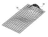
パネル10は、圧電素子30が取り付けられた取付領域だけでなく、取付領域から離れた領域も湾曲振動する。パネル10は、振動する領域において、当該パネル10の主面と交差する方向に振動する箇所を複数有し、当該複数の箇所の各々において、振動の振幅の値が、時間とともにプラスからマイナスに、あるいはその逆に変化する。パネル10は、ある瞬間において、振動の振幅が相対的に大きい部分と振動の振幅が相対的に小さい部分とが一見パネル10の略全体にランダムにあるいは周期的に分布した振動をする。即ちパネル10全域にわたって、複数の波の振動が検出される。利用者が例えば5N〜10Nの力で自身の体にパネル10を押し付けた場合であっても、パネル10の上述したような振動が減衰しないためには、制御部50が圧電素子30に対して印加する最大電圧は、±15Vであってよい。そのため、利用者は、上述した圧電素子30の取付領域から離れた領域、例えばパネル10の中央部に耳を接触させて音を聞くことができる。 The
ここで、パネル10は、利用者の耳とほぼ同じ大きさであってよい。また、パネル10は、図2に示すように、利用者の耳よりも大きいものであってもよい。この場合、利用者が音を聞く際、電子機器1のパネル10により耳全体が覆われやすいことから、音(ノイズ)を外耳道に入りにくくできる。パネル10は、対耳輪下脚(下対輪脚)から対耳珠までの間の距離に相当する長さと、耳珠から対耳輪までの間の距離に相当する幅とを有する領域よりも広い領域が振動すればよい。パネル10は、好ましくは、耳輪における対耳輪上脚(上対輪脚)近傍の部位から耳垂までの間の距離に相当する長さと、耳珠から耳輪における対耳輪近傍の部位までの間の距離に相当する幅を有する領域が振動すればよい。上記の長さおよび幅を有する領域は、長方形状の領域であってもよいし、上記の長さを長径、上記の幅を短径とする楕円形状であってもよい。日本人の耳の平均的な大きさは、社団法人 人間生活工学研究センター(HQL)作成の日本人の人体寸法データベース(1992−1994)等を参照すれば知ることができる。なお、パネル10が日本人の耳の平均的な大きさ以上の大きさであれば、パネル10は概ね外国人の耳全体を覆うことができる大きさであると考えられる。上記のような寸法や形状を有することで、パネル10は、ユーザの耳を覆うことができ、耳に当てたときの位置ずれに対して寛容になる。 Here, the
上記の電子機器1は、パネル10の振動により、気導音と、利用者の体の一部(例えば外耳の軟骨)を介する振動音とを利用者に伝えることができる。そのため、従来のダイナミックレシーバと同等の音量の音を出力する場合、パネル10が振動することで空気の振動により電子機器1の周囲へ伝わる音は、ダイナミックレシーバと比較して少ない。したがって、例えば録音されたメッセージを電車内等で聞く場合等に適している。 The electronic device 1 can transmit air conduction sound and vibration sound via a part of the user's body (for example, cartilage of the outer ear) to the user by the vibration of the
また、上記の電子機器1は、パネル10の振動によって振動音を伝えるため、例えば利用者がイヤホンまたはヘッドホンを身につけていても、それらに電子機器1を接触させることで、利用者はイヤホンまたはヘッドホンおよび体の一部を介して音を聞くことができる。 In addition, since the electronic device 1 transmits vibration sound due to the vibration of the
上記の電子機器1は、パネル10の振動により利用者に音を伝える。そのため、電子機器1が別途ダイナミックレシーバを備えない場合、音声伝達のための開口部(放音口)を筐体に形成する必要がなく、電子機器1の防水構造が簡略化できる。なお、電子機器1がダイナミックレシーバを備える場合、放音口は、気体は通すが液体は通さない部材によって閉塞されるとよい。気体は通すが液体は通さない部材は、例えばゴアテックス(登録商標)である。 The electronic device 1 transmits sound to the user by the vibration of the
図3は、一の実施形態に係る電子機器1の実装構造の要部を概略的に示す図である。図3(a)は正面図、図3(b)は図3(a)におけるb−b線に沿った断面図、図3(c)は図3(a)におけるc−c線に沿った断面図である。図3に示す電子機器1はパネル10として表示部20を保護するカバーパネル(アクリル板)が上側の筐体60aの前面に配され、入力部40が下側の筐体60bに配された折りたたみ式の携帯電話である。 FIG. 3 is a diagram schematically illustrating a main part of the mounting structure of the electronic device 1 according to the embodiment. 3 (a) is a front view, FIG. 3 (b) is a cross-sectional view taken along line bb in FIG. 3 (a), and FIG. 3 (c) is taken along line cc in FIG. 3 (a). It is sectional drawing. The electronic device 1 shown in FIG. 3 has a folding panel in which a cover panel (acrylic plate) that protects the
パネル10と圧電素子30との間には、補強部材80が配置されてもよい。補強部材80は、例えば樹脂製の板、板金またはガラス繊維を含む樹脂製の板である。すなわち、一の実施形態に係る電子機器1は、圧電素子30と補強部材80とが接合部材70により接着され、さらに補強部材80とパネル10とが接合部材70により接着される構造である。 A reinforcing
また、本実施形態では、表示部20は、パネル10に接着されるのではなく、筐体60aによって支持されている。すなわち本実施形態に係る電子機器1は、表示部20がパネル10と離間しており、表示部20と筐体60aの一部である支持部90とが接合部材70により接着される構造である。なお、支持部90は、筐体60の一部としての構成に限定されず、金属や樹脂等により筐体60から独立した部材として構成することが可能である。 In the present embodiment, the
下側の筐体60bには、開口42が形成されている。また、筐体60bには、開口42と対向するように、筐体60bに内蔵された回路基板43にマイク7が搭載されている。したがって、マイク7は、入力部40が面する側に指向性を有している。 An
本実施形態に係る電子機器1によれば、パネル10に補強部材80を介して取り付けられた圧電素子30の変形に起因して補強部材80およびパネル10が変形し、当該変形するパネル10に接触する対象物に対して気導音と振動音とを伝える。これにより、圧電素子30自体を耳に当てることなく気導音と振動音とを利用者に伝えることができる。また、圧電素子30は、パネル10の筐体60aの内部側の面に取り付けられる。このため、圧電素子30を筐体60aの外面に突出させることなく気導音と振動音とを利用者に伝えることができる。また、パネル10は、圧電素子30が取り付けられた取付領域だけでなく、パネル10のいずれの箇所においても気導音と振動音とを伝えるための変形が発生する。このため、利用者は、空気を介する気導音に加え、パネル10の任意の位置に耳を接触させて振動音を聞くことができる。 According to the electronic apparatus 1 according to the present embodiment, the reinforcing
また、圧電素子30とパネル10との間に補強部材80を配置することで、例えばパネル10に外力が加わった場合に、その外力が圧電素子30に伝達され圧電素子30が破損する可能性を低減することができる。また、人体にパネル10を強く接触させても、パネル10の振動が減衰しにくくできる。また、圧電素子30とパネル10との間に補強部材80を配置することで、パネル10の共振周波数が下がり、低周波数帯域の音響特性が向上する。なお、補強部材80に換えて、板状の錘を接合部材70により圧電素子30に取り付けてもよい。 Further, by arranging the reinforcing
パネル10は、例えば静電容量方式のタッチパネルを構成するものでもよく、その場合、接合部材70を介して筐体60aに支持されて、3N〜10Nの押圧力で押圧可能に構成されている。表示部20は、回路基板130に接続されている。また、パネル10の一方向における一端側である上部背面には、パネル10とともに振動体を構成する圧電素子30が接合部材70を介して接合されている。圧電素子30は、長方形状を成し、その長辺がパネル10の短辺に沿うように接合される。なお、接合部材70は、熱硬化性あるいは紫外線硬化性等を有する接着剤や両面テープ等であり、例えば無色透明のアクリル系紫外線硬化型接着剤である光学弾性樹脂でもよい。 The
入力部40は、パネル10の長手方向の他端部(下部)側において筐体60bに支持されている。また、入力部40には、破線で示すように、マイクの開口42が形成されている。つまり、長方形状の筐体60aの上部側に圧電素子30が配置され、筺体60bの下部側に開口42が形成されている。マイク7は、開口42と対向するように、回路基板130に搭載されている。したがって、マイク7は、パネル10が面する側に指向性を有している。 The
図4は、本発明の一実施形態に係る電子機器1のパネル10の振動の一例を示す図である。本実施形態に係る電子機器1では、パネル10がガラス板と比較し剛性の低いアクリル板であり、また、パネル10の背面に表示部20が接着されていないため、表示部20が接着されたタイプの電子機器に比べ、圧電素子30により生じる振幅が大きくできる。また、パネル10は、圧電素子30が取り付けられた取付領域だけでなく、取付領域から離れた領域も振動する。このため、利用者は、空気を介する気導音に加え、パネル10の任意の位置に耳を接触させて振動音を聞くことができる。 FIG. 4 is a diagram illustrating an example of vibration of the
本実施形態に係る電子機器1においては、マイク7で集音される音に基づいて、第1あるいは第2のハウリング低減処理を実行する。 In the electronic device 1 according to the present embodiment, the first or second howling reduction process is executed based on the sound collected by the
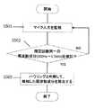
図5は、電子機器1による通話機能あるいは補聴機能実行時の第1のハウリング低減処理の動作を示すフローチャートである。なお、補聴機能とは、周囲の音をマイク7にて集音し、当該集音した音を、スピーカ機能により大音量化して再生することにより、少し音が聞こえにくくなったと感じているユーザへの聞こえをアシストする機能である。 FIG. 5 is a flowchart showing the operation of the first howling reduction process when the electronic device 1 executes the call function or the hearing aid function. Note that the hearing aid function refers to a user who feels that the sound is a little difficult to hear by collecting ambient sounds with the
S501では、制御部50は、無線通信部5による音声着信や補聴機能の実行操作を検出すると、スピーカ機能を起動させるとともに、マイク7で集音される音を分析することによりマイク入力を監視する。監視される音は、例えば、マイク7の出力信号を一定時間サンプリングし、そのサンプリング出力を、伝送する音声周波数帯域内で周波数解析して検出することができる。 In S <b> 501, when the
S502では、制御部50が、所定の範囲内、例えば300Hzから1.5kHzの低周波数帯域において、所定の時間内に、同じ周波数の音が規定回数以上、例えば5回以上、検出されるか否かを判定する。規定回数以上のときは、S503へ移行する。同じ周波数の音が規定回数以上、例えば5回以上、検出されない場合は、S501へ移行する。 In S502, whether or not the
S503では、規定回数以上、同じ周波数の音が入力されているため、ハウリングが生じていると判断して規定回数以上検出された周波数の音を低減あるいは除去した信号に基づいて、音を再生する。なお、スピーカ機能を実行中は、S501からS503が繰り返されるとよい。 In S503, since the sound having the same frequency is input more than the specified number of times, it is determined that howling has occurred, and the sound is reproduced based on the signal obtained by reducing or removing the sound having the frequency detected more than the specified number of times. . Note that S501 to S503 may be repeated while the speaker function is being executed.
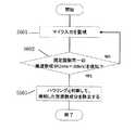
図6は、電子機器1による通話機能あるいは補聴機能実行時の第2のハウリング低減処理の動作を示すフローチャートである。 FIG. 6 is a flowchart showing the operation of the second howling reduction process when the electronic device 1 executes the call function or the hearing aid function.
S601では、制御部50は、無線通信部5による音声着信や補聴機能の実行操作を検出すると、スピーカ機能を起動させるとともに、マイク7で集音される音を分析することによりマイク入力を監視する。監視される音は、例えば、マイク7の出力信号を一定時間サンプリングし、そのサンプリング出力を、伝送する音声周波数帯域内で周波数解析して検出することができる。 In S <b> 601, when the
S602では、制御部50が、所定の範囲内、例えば1kHzから20kHzの高周波数帯域において、同じ周波数の音が規定回数以上、例えば5回以上、検出されるか否かを判定する。規定回数以上のときは、S603へ移行する。同じ周波数の音が規定回数以上、例えば5回以上、検出されない場合は、S601へ移行する。 In S602, the
S603では、規定回数以上、同じ周波数の音が入力されているため、ハウリングが生じていると判断して規定回数以上検出された周波数の音を低減あるいは除去して音を再生する。なお、スピーカ機能を実行中は、S601からS603が繰り返されるとよい。 In S603, since the sound having the same frequency is input more than the specified number of times, it is determined that howling has occurred, and the sound having the frequency detected more than the specified number of times is reduced or removed to reproduce the sound. Note that S601 to S603 are preferably repeated while the speaker function is being executed.
なお、例えば気導音と振動音とを発生させる振動体を利用した電子機器では、振動体からの振動が人体に伝わり、振動した状態の人体によってマイク7の開口42が覆われるときに、ハウリングが生じやすいことが発明者らにより見出された。したがって、気導音と振動音とを発生させる振動体を利用した電子機器では、このようなハウリング低減処理は有効である。 For example, in an electronic apparatus using a vibrating body that generates air conduction sound and vibration sound, howling is performed when vibration from the vibrating body is transmitted to the human body and the
また、マイク7への音の入力経路として筺体外部から筐体内部のマイクへと通じる音の経路(開口42)が一つしかない場合のほうが、マイクへの音の浸入経路を塞がれたことによるハウリングが生じやすいことが発明者らによって見出された。従ってこのような電子機器においてハウリング低減処理は有効である。 In addition, when there is only one sound path (opening 42) from the outside of the housing to the microphone inside the housing as the sound input path to the
また、低周波数帯域は、高周波数帯域よりも、おなじ規定回数を検出するまでの時間が、当該周波数の高低に起因して長いため、低周波数帯域におけるハウリングの検出と、高周波数帯域におけるハウリングの検出とを分離して行ってもよい。これにより、高周波数帯域のほうが、低周波数帯域よりも早くに、ハウリングの検出が行われ、低周波数帯域の検出結果を待つことなく、高周波数帯域でのハウリング低減処理が行える。 Also, in the low frequency band, since the time until the same specified number of times is detected is longer than that in the high frequency band due to the level of the frequency, howling detection in the low frequency band and howling in the high frequency band are performed. Detection may be performed separately. Accordingly, howling is detected in the high frequency band earlier than in the low frequency band, and howling reduction processing in the high frequency band can be performed without waiting for the detection result in the low frequency band.
また、低周波数帯域におけるハウリング低減処理と高周波数帯域におけるハウリング低減処理とでは、上記規定回数を異ならせてもよい。例えば、低周波数帯域の場合における規定回数を、高周波数帯域の場合における規定回数よりも小さくするとよい。この場合、低周波数帯域の場合と高周波数帯域の場合とで、同じ規定回数を閾値としている場合に比較して、低周波数帯域におけるハウリング状態の検出が、高周波数帯域におけるハウリング状態の検出にそれほど遅れることなく、実行できる。 Further, the prescribed number of times may be different between howling reduction processing in the low frequency band and howling reduction processing in the high frequency band. For example, the specified number of times in the low frequency band may be smaller than the specified number of times in the high frequency band. In this case, compared to the case where the same specified number of times is used as the threshold value in the case of the low frequency band and the case of the high frequency band, the detection of the howling state in the low frequency band is much less than the detection of the howling state in the high frequency band. It can be executed without delay.
また、低周波数帯域の検出帯域と高周波数帯域との検出帯域を重ねてもよく、この場合、検出帯域の抜けが生じにくい。 Further, the detection band of the low frequency band and the detection band of the high frequency band may be overlapped. In this case, the detection band is not easily lost.
本発明を諸図面や実施例に基づき説明してきたが、当業者であれば本開示に基づき種々の変形や修正を行うことが容易であることに注意されたい。従って、これらの変形や修正は本発明の範囲に含まれることに留意されたい。例えば、各部材、各ステップなどに含まれる機能などは論理的に矛盾しないように再配置可能であり、複数の構成部やステップなどを1つに組み合わせたり、或いは分割したりすることが可能である。 Although the present invention has been described based on the drawings and examples, it should be noted that those skilled in the art can easily make various modifications and corrections based on the present disclosure. Therefore, it should be noted that these variations and modifications are included in the scope of the present invention. For example, the functions included in each member, each step, etc. can be rearranged so that there is no logical contradiction, and a plurality of components, steps, etc. can be combined into one or divided. is there.
また、上記の電子機器1においては、圧電素子30はパネル10に貼り付けられているが、パネル10と異なる場所に取り付けられてもよい。 In the electronic device 1 described above, the
また、パネル10は、表示パネル、操作パネル、カバーパネル、充電池を取り外し可能とするためのリッドパネルのいずれかの一部または全部を構成することができる。特に、パネル10が表示パネルのとき、圧電素子30は、表示機能のための表示領域の外側に配置される。これにより、表示を阻害しにくいという利点がある。操作パネルは、例えば図3の折り畳み型携帯電話においては、操作キーのキートップが一体に形成され操作部側(下側)の筐体の一面を構成する部材であるシートキーを含む。 Further, the
なお、上記実施形態では、パネル10と圧電素子30とを接着する接合部材およびパネル10と筐体60(60a)とを接着する接合部材等を同一の符号を有する接合部材70として説明した。しかしながら、接合部材は、接合する対象である部材に応じて適宜異なるものが用いられてよい。 In the above embodiment, the bonding member that bonds the
1 電子機器
5 無線通信部
7 マイク
10 パネル
20 表示部
30 圧電素子
40 入力部
42 開口
43 回路基板
44 集音口
50 制御部
60、60a、60b 筐体
70 接合部材
80 補強部材
90 支持部
130 回路基板DESCRIPTION OF SYMBOLS 1
Claims (25)
Translated fromJapanese前記筺体に配置された振動体と、
前記筺体に配置されたマイクと、を有し、
前記振動体は、圧電素子と、該圧電素子を支持するパネルとを備え、
前記圧電素子が、前記振動体の前記パネルを振動させることにより、前記圧電素子の長辺方向において該圧電素子の直上がその周囲と比較して最も高く隆起するように、前記圧電素子によって前記パネルが曲げられ、当該パネルに接触する前記接触領域が振動して、気導音と、人体を介して伝える振動音とを発生させるスピーカ機能を実行する電子機器であって、
前記スピーカ機能を実行中に、ハウリング低減処理を実行する電子機器。A housing,
A vibrating body disposed on the housing;
A microphone disposed in the housing,
The vibrating body includes a piezoelectric element and a panel that supports the piezoelectric element,
Thepiezoelectric element vibratesthe panel of the vibrating body, so thatthe paneldirectly above the piezoelectric element protrudes higher than the surrounding area in the long side direction of the piezoelectric element. Is an electronic device that performs a speaker function that generatesan air conduction sound and a vibration sound transmitted through a human body byvibrating the contact region that is bent and contacting the panel ,
An electronic device that executes howling reduction processing while the speaker function is being executed.
請求項1に記載の電子機器。The howling reduction processing is executed when the sound collected from the microphone includes the sound of the same frequency within a predetermined period more than the specified number of times.
The electronic device according to claim 1.
請求項1または請求項2に記載の電子機器。The howling reduction processing is performed for a low frequency band from 300 Hz to 1.5 kHz.
The electronic device according to claim 1 or 2.
請求項1乃至請求項3のいずれかに記載の電子機器。The howling reduction processing is performed for a high frequency band from 1 kHz to 20 kHz.
The electronic device according to claim 1.
請求項1乃至請求項4のいずれかに記載の電子機器。The howling reduction processing is performed by removing the sound of the detected frequency more than a predetermined number of times within a predetermined time from the sound reproduced by the speaker function.
The electronic device according to claim 1.
前記ハウリング低減処理は、通話中に実行される
請求項1乃至請求項5のいずれかに記載の電子機器。It also has a call function,
The howling reduction process is executed during a call.
The electronic device according to claim 1.
前記ハウリング低減処理は、補聴機能実行中に行われる
請求項1乃至請求項5のいずれかに記載の電子機器。Further equipped with hearing aids,
The howling reduction process is performed while the hearing aid function is being executed.
The electronic device according to claim 1.
請求項1乃至8のいずれかに記載の電子機器。The microphone is arranged at a position that is assumed to be blocked by the user in advance.
The electronic device according to claim 1.
前記筺体に配置された振動体と、
前記筺体に配置されたマイクと、を有し、
前記振動体は、圧電素子と、該圧電素子を支持するパネルとを備え、
前記圧電素子が、前記振動体の前記パネルを振動させることにより、前記圧電素子の長辺方向において該圧電素子の直上がその周囲と比較して最も高く隆起するように、前記圧電素子によって前記パネルが曲げられ、当該パネルに接触する前記接触領域が振動して、気導音と、人体を介して伝える振動音とを発生させるスピーカ機能を実行するとともに、
前記スピーカ機能を実行中に、低周波数帯域におけるハウリング低減処理と、高周波数帯域におけるハウリング低減処理とを実行する電子機器。A housing,
A vibrating body disposed on the housing;
A microphone disposed in the housing,
The vibrating body includes a piezoelectric element and a panel that supports the piezoelectric element,
The piezoelectric element vibrates the panel of the vibrating body, so that the panel directly above the piezoelectric element protrudes higher than the surrounding area in the long side direction of the piezoelectric element. And a speaker function that generatesan air conduction sound and a vibration sound transmitted through the human body byvibrating the contact area that contacts the panel .
An electronic device that executes a howling reduction process in a low frequency band and a howling reduction process in a high frequency band while executing the speaker function.
前記低周波数帯域と高周波数帯域とは、前記規定回数の設定を異ならせている請求項10に記載の電子機器。The howling reduction processing is executed when the sound collected from the microphone includes a sound of the same frequency within a predetermined period, a predetermined number of times,
Wherein the low and high frequency bands, an electronic device according toclaim 10 in which at different settings of the prescribed number of times.
請求項1乃至11のいずれかに記載の電子機器。The microphone has one opening
The electronic device according to claim 1.
Priority Applications (3)
| Application Number | Priority Date | Filing Date | Title |
|---|---|---|---|
| JP2012122505AJP5952092B2 (en) | 2012-05-29 | 2012-05-29 | Electronics |
| PCT/JP2013/003310WO2013179629A1 (en) | 2012-05-29 | 2013-05-24 | Electronic device |
| US14/404,590US9571932B2 (en) | 2012-05-29 | 2013-05-24 | Electronic device |
Applications Claiming Priority (1)
| Application Number | Priority Date | Filing Date | Title |
|---|---|---|---|
| JP2012122505AJP5952092B2 (en) | 2012-05-29 | 2012-05-29 | Electronics |
Publications (2)
| Publication Number | Publication Date |
|---|---|
| JP2013247660A JP2013247660A (en) | 2013-12-09 |
| JP5952092B2true JP5952092B2 (en) | 2016-07-13 |
Family
ID=49672854
Family Applications (1)
| Application Number | Title | Priority Date | Filing Date |
|---|---|---|---|
| JP2012122505AActiveJP5952092B2 (en) | 2012-05-29 | 2012-05-29 | Electronics |
Country Status (3)
| Country | Link |
|---|---|
| US (1) | US9571932B2 (en) |
| JP (1) | JP5952092B2 (en) |
| WO (1) | WO2013179629A1 (en) |
Families Citing this family (15)
| Publication number | Priority date | Publication date | Assignee | Title |
|---|---|---|---|---|
| KR101604521B1 (en) | 2010-12-27 | 2016-03-17 | 로무 가부시키가이샤 | Transmitter/receiver unit and receiver unit |
| TWI660618B (en) | 2012-01-20 | 2019-05-21 | 日商精良股份有限公司 | Mobile phone |
| TWI724317B (en) | 2012-06-29 | 2021-04-11 | 日商精良股份有限公司 | Headphones and stereo headphones |
| CN108551507A (en) | 2013-08-23 | 2018-09-18 | 罗姆股份有限公司 | Exhalation/incoming call communication, receiver, earphone, business card, non-contact IC card, mobile phone and its application method |
| US9261915B2 (en)* | 2013-12-21 | 2016-02-16 | Kyocera Corporation | Electronic apparatus, light-transmissive cover plate, and portable device |
| JP2015136091A (en)* | 2013-12-21 | 2015-07-27 | 京セラ株式会社 | Electronic device and translucent cover member |
| US9151473B2 (en)* | 2013-12-24 | 2015-10-06 | Kyocera Corporation | Electronic apparatus, light-transmissive cover plate, and portable device |
| JP6551919B2 (en) | 2014-08-20 | 2019-07-31 | 株式会社ファインウェル | Watch system, watch detection device and watch notification device |
| CN107113481B (en) | 2014-12-18 | 2019-06-28 | 株式会社精好 | Cartilage conduction hearing device using electromagnetic vibration unit and electromagnetic vibration unit |
| EP3323567B1 (en) | 2015-07-15 | 2020-02-12 | FINEWELL Co., Ltd. | Robot and robot system |
| JP6551929B2 (en) | 2015-09-16 | 2019-07-31 | 株式会社ファインウェル | Watch with earpiece function |
| US10778824B2 (en) | 2016-01-19 | 2020-09-15 | Finewell Co., Ltd. | Pen-type handset |
| GB2560878B (en)* | 2017-02-24 | 2021-10-27 | Google Llc | A panel loudspeaker controller and a panel loudspeaker |
| KR102386452B1 (en)* | 2018-05-02 | 2022-04-14 | 삼성디스플레이 주식회사 | Display device |
| JP2020053948A (en) | 2018-09-28 | 2020-04-02 | 株式会社ファインウェル | Hearing device |
Family Cites Families (11)
| Publication number | Priority date | Publication date | Assignee | Title |
|---|---|---|---|---|
| US4517417A (en)* | 1982-03-25 | 1985-05-14 | Honda Giken Kogyo Kabushiki Kaisha | Communication system for a motor vehicle |
| US5115472A (en)* | 1988-10-07 | 1992-05-19 | Park Kyung T | Electroacoustic novelties |
| JPH02206266A (en)* | 1989-02-06 | 1990-08-16 | Fujitsu Ltd | Howling detecting/decreasing circuit |
| JP4681163B2 (en)* | 2001-07-16 | 2011-05-11 | パナソニック株式会社 | Howling detection and suppression device, acoustic device including the same, and howling detection and suppression method |
| JP2003244792A (en)* | 2002-02-15 | 2003-08-29 | Pioneer Electronic Corp | Piezoelectric film speaker and mobile information terminal |
| US7310427B2 (en)* | 2002-08-01 | 2007-12-18 | Virginia Commonwealth University | Recreational bone conduction audio device, system |
| JP2004187031A (en)* | 2002-12-04 | 2004-07-02 | Temuko Japan:Kk | Mobile phone using bone conduction speaker |
| JP2005348193A (en)* | 2004-06-04 | 2005-12-15 | Nec Tokin Corp | Receiver |
| JP4779526B2 (en)* | 2005-09-15 | 2011-09-28 | 日本電気株式会社 | Panel speaker |
| JP2007180827A (en)* | 2005-12-27 | 2007-07-12 | Citizen Electronics Co Ltd | Panel-type speaker |
| JP2011091719A (en)* | 2009-10-26 | 2011-05-06 | Authentic Ltd | Flexural oscillating actuator |
- 2012
- 2012-05-29JPJP2012122505Apatent/JP5952092B2/enactiveActive
- 2013
- 2013-05-24WOPCT/JP2013/003310patent/WO2013179629A1/enactiveApplication Filing
- 2013-05-24USUS14/404,590patent/US9571932B2/ennot_activeExpired - Fee Related
Also Published As
| Publication number | Publication date |
|---|---|
| WO2013179629A1 (en) | 2013-12-05 |
| US9571932B2 (en) | 2017-02-14 |
| JP2013247660A (en) | 2013-12-09 |
| US20150110318A1 (en) | 2015-04-23 |
Similar Documents
| Publication | Publication Date | Title |
|---|---|---|
| JP5952092B2 (en) | Electronics | |
| JP5818923B2 (en) | Electronics | |
| JP5255142B1 (en) | Electronics | |
| JP5734473B2 (en) | Electronics | |
| JP5812925B2 (en) | Electronics | |
| JP5818922B2 (en) | Electronics | |
| JP5995519B2 (en) | Electronics | |
| JP5968018B2 (en) | Electronics | |
| JP5968050B2 (en) | Electronics | |
| WO2013175780A1 (en) | Electronic equipment and method of controlling electronic equipment | |
| JP6122254B2 (en) | Electronics | |
| JP6006530B2 (en) | Electronics | |
| JP5951355B2 (en) | Electronics | |
| JP6073074B2 (en) | Electronics | |
| JP2013243622A (en) | Electronic apparatus | |
| JP5856199B2 (en) | Electronics | |
| JP6080382B2 (en) | Electronics | |
| JP2013231913A (en) | Electronic apparatus | |
| JP2014027633A (en) | Electronic apparatus |
Legal Events
| Date | Code | Title | Description |
|---|---|---|---|
| A621 | Written request for application examination | Free format text:JAPANESE INTERMEDIATE CODE: A621 Effective date:20140916 | |
| A131 | Notification of reasons for refusal | Free format text:JAPANESE INTERMEDIATE CODE: A131 Effective date:20150908 | |
| A521 | Written amendment | Free format text:JAPANESE INTERMEDIATE CODE: A523 Effective date:20151105 | |
| TRDD | Decision of grant or rejection written | ||
| A01 | Written decision to grant a patent or to grant a registration (utility model) | Free format text:JAPANESE INTERMEDIATE CODE: A01 Effective date:20160510 | |
| A61 | First payment of annual fees (during grant procedure) | Free format text:JAPANESE INTERMEDIATE CODE: A61 Effective date:20160609 | |
| R150 | Certificate of patent or registration of utility model | Ref document number:5952092 Country of ref document:JP Free format text:JAPANESE INTERMEDIATE CODE: R150 |