JP5947759B2 - Camera unit - Google Patents
Camera unitDownload PDFInfo
- Publication number
- JP5947759B2 JP5947759B2JP2013152423AJP2013152423AJP5947759B2JP 5947759 B2JP5947759 B2JP 5947759B2JP 2013152423 AJP2013152423 AJP 2013152423AJP 2013152423 AJP2013152423 AJP 2013152423AJP 5947759 B2JP5947759 B2JP 5947759B2
- Authority
- JP
- Japan
- Prior art keywords
- camera body
- bracket
- leaf spring
- camera
- hook
- Prior art date
- Legal status (The legal status is an assumption and is not a legal conclusion. Google has not performed a legal analysis and makes no representation as to the accuracy of the status listed.)
- Expired - Fee Related
Links
Images


Classifications
- G—PHYSICS
- G03—PHOTOGRAPHY; CINEMATOGRAPHY; ANALOGOUS TECHNIQUES USING WAVES OTHER THAN OPTICAL WAVES; ELECTROGRAPHY; HOLOGRAPHY
- G03B—APPARATUS OR ARRANGEMENTS FOR TAKING PHOTOGRAPHS OR FOR PROJECTING OR VIEWING THEM; APPARATUS OR ARRANGEMENTS EMPLOYING ANALOGOUS TECHNIQUES USING WAVES OTHER THAN OPTICAL WAVES; ACCESSORIES THEREFOR
- G03B17/00—Details of cameras or camera bodies; Accessories therefor
- G03B17/56—Accessories
- G03B17/561—Support related camera accessories
- B—PERFORMING OPERATIONS; TRANSPORTING
- B60—VEHICLES IN GENERAL
- B60R—VEHICLES, VEHICLE FITTINGS, OR VEHICLE PARTS, NOT OTHERWISE PROVIDED FOR
- B60R11/00—Arrangements for holding or mounting articles, not otherwise provided for
- B60R11/04—Mounting of cameras operative during drive; Arrangement of controls thereof relative to the vehicle
- F—MECHANICAL ENGINEERING; LIGHTING; HEATING; WEAPONS; BLASTING
- F16—ENGINEERING ELEMENTS AND UNITS; GENERAL MEASURES FOR PRODUCING AND MAINTAINING EFFECTIVE FUNCTIONING OF MACHINES OR INSTALLATIONS; THERMAL INSULATION IN GENERAL
- F16M—FRAMES, CASINGS OR BEDS OF ENGINES, MACHINES OR APPARATUS, NOT SPECIFIC TO ENGINES, MACHINES OR APPARATUS PROVIDED FOR ELSEWHERE; STANDS; SUPPORTS
- F16M11/00—Stands or trestles as supports for apparatus or articles placed thereon ; Stands for scientific apparatus such as gravitational force meters
- F16M11/02—Heads
- F16M11/04—Means for attachment of apparatus; Means allowing adjustment of the apparatus relatively to the stand
- F16M11/041—Allowing quick release of the apparatus
- F—MECHANICAL ENGINEERING; LIGHTING; HEATING; WEAPONS; BLASTING
- F16—ENGINEERING ELEMENTS AND UNITS; GENERAL MEASURES FOR PRODUCING AND MAINTAINING EFFECTIVE FUNCTIONING OF MACHINES OR INSTALLATIONS; THERMAL INSULATION IN GENERAL
- F16M—FRAMES, CASINGS OR BEDS OF ENGINES, MACHINES OR APPARATUS, NOT SPECIFIC TO ENGINES, MACHINES OR APPARATUS PROVIDED FOR ELSEWHERE; STANDS; SUPPORTS
- F16M13/00—Other supports for positioning apparatus or articles; Means for steadying hand-held apparatus or articles
- F16M13/02—Other supports for positioning apparatus or articles; Means for steadying hand-held apparatus or articles for supporting on, or attaching to, an object, e.g. tree, gate, window-frame, cycle
- B—PERFORMING OPERATIONS; TRANSPORTING
- B60—VEHICLES IN GENERAL
- B60R—VEHICLES, VEHICLE FITTINGS, OR VEHICLE PARTS, NOT OTHERWISE PROVIDED FOR
- B60R11/00—Arrangements for holding or mounting articles, not otherwise provided for
- B60R2011/0001—Arrangements for holding or mounting articles, not otherwise provided for characterised by position
- B60R2011/0003—Arrangements for holding or mounting articles, not otherwise provided for characterised by position inside the vehicle
- B60R2011/0026—Windows, e.g. windscreen
- B—PERFORMING OPERATIONS; TRANSPORTING
- B60—VEHICLES IN GENERAL
- B60R—VEHICLES, VEHICLE FITTINGS, OR VEHICLE PARTS, NOT OTHERWISE PROVIDED FOR
- B60R11/00—Arrangements for holding or mounting articles, not otherwise provided for
- B60R2011/0042—Arrangements for holding or mounting articles, not otherwise provided for characterised by mounting means
- B60R2011/0049—Arrangements for holding or mounting articles, not otherwise provided for characterised by mounting means for non integrated articles
- B60R2011/005—Connection with the vehicle part
- B60R2011/0063—Connection with the vehicle part using adhesive means, e.g. hook and loop fasteners
- B—PERFORMING OPERATIONS; TRANSPORTING
- B60—VEHICLES IN GENERAL
- B60R—VEHICLES, VEHICLE FITTINGS, OR VEHICLE PARTS, NOT OTHERWISE PROVIDED FOR
- B60R11/00—Arrangements for holding or mounting articles, not otherwise provided for
- B60R2011/0042—Arrangements for holding or mounting articles, not otherwise provided for characterised by mounting means
- B60R2011/0049—Arrangements for holding or mounting articles, not otherwise provided for characterised by mounting means for non integrated articles
- B60R2011/0064—Connection with the article
- B60R2011/0071—Connection with the article using latches, clips, clamps, straps or the like
- B—PERFORMING OPERATIONS; TRANSPORTING
- B60—VEHICLES IN GENERAL
- B60R—VEHICLES, VEHICLE FITTINGS, OR VEHICLE PARTS, NOT OTHERWISE PROVIDED FOR
- B60R11/00—Arrangements for holding or mounting articles, not otherwise provided for
- B60R2011/0042—Arrangements for holding or mounting articles, not otherwise provided for characterised by mounting means
- B60R2011/0049—Arrangements for holding or mounting articles, not otherwise provided for characterised by mounting means for non integrated articles
- B60R2011/0064—Connection with the article
- B60R2011/0077—Connection with the article using adhesive means, e.g. hook and loop fasteners
Landscapes
- Engineering & Computer Science (AREA)
- General Engineering & Computer Science (AREA)
- Mechanical Engineering (AREA)
- Physics & Mathematics (AREA)
- General Physics & Mathematics (AREA)
- Fittings On The Vehicle Exterior For Carrying Loads, And Devices For Holding Or Mounting Articles (AREA)
- Accessories Of Cameras (AREA)
Description
Translated fromJapanese本発明は、カメラ本体と、前記カメラ本体を着脱自在に支持し前記カメラ本体を取付け対象物(例えば、車両のフロントガラス)に固定するブラケットとを有するカメラユニットに関する。 The present invention relates to a camera unit having a camera body and a bracket that detachably supports the camera body and fixes the camera body to an attachment object (for example, a windshield of a vehicle).
特許文献1では、容易にカメラを着脱することができ、その上で装着時の位置決めを良好に行うことができる車載カメラの取付構造の提供を目的としている([0005]、要約)。この目的を達成するため、特許文献1では、車体側に固定されるベース12と、カメラ11と、ベース12に対しカメラ11をスライドによって着脱可能に係合させるスライド機構47と、ベース12及びカメラ11のいずれか一方に設けられ装着時のカメラ11の装着時スライド方向に対し前側の左右及び後側の左右にそれぞれ配置される突起部28、29と、ベース12及びカメラ11のいずれか他方に設けられ前側の左右及び後側の左右の突起部28、29にそれぞれ左右方向に当接してベース12に対するカメラ11の位置決めを行う当接部39、41とを備える(要約)。 Patent Document 1 aims to provide a mounting structure for an in-vehicle camera that can easily attach and detach a camera and can be well positioned when mounted ([0005], summary). In order to achieve this object, in Patent Document 1, a
フロントガラスに固定されたベース12に対して、カメラ11を取り付ける場合、特許文献1の図1(b)から図1(c)に示すように、スライド機構47を構成する左右一対のスライドガイド部26、26を左右一対のスライド凹部42、42に挿入させるようにして、カメラ11を車両前後方向前方にスライドさせる([0036])。 When the camera 11 is attached to the
上記のように、特許文献1では、カメラ11をスライドさせて固定する構造である。このため、特許文献1では、フロントガラス近傍においてスライドさせるスペースを確保する必要があり、フロントガラス上部の設計自由度が制限されてしまう。フロントガラス近傍以外の部位においてカメラ11を固定する場合も同様である。 As described above, Patent Document 1 has a structure in which the camera 11 is slid and fixed. For this reason, in patent document 1, it is necessary to ensure the space to slide in the windshield vicinity, and the freedom degree of design of the windshield upper part will be restrict | limited. The same applies when the camera 11 is fixed at a portion other than the vicinity of the windshield.
本発明はこのような課題を考慮してなされたものであり、設計自由度を向上可能なカメラユニットを提供することを目的とする。 The present invention has been made in consideration of such problems, and an object thereof is to provide a camera unit capable of improving the degree of freedom in design.
本発明に係るカメラユニットは、カメラ本体と、前記カメラ本体を着脱自在に支持し前記カメラ本体を取付け対象物に固定するブラケットとを有するものであって、前記カメラ本体は、前記ブラケットに引っ掛ける鉤状部を備え、前記ブラケットは、前記鉤状部を引っ掛けて前記カメラ本体を旋回可能に支持する第1支持部と、前記カメラ本体を固定支持する第2支持部とを備え、前記第2支持部は、主面が前記カメラ本体に面する板ばねを備え、前記板ばねの一端は、ブラケット本体に固定され、前記板ばねの他端は、通常状態において前記カメラ本体を押圧する押圧位置と、前記カメラ本体を取り外す際、前記カメラ本体から離間する離間位置とを切り替え可能であり、前記ブラケットの前記板ばねは、前記カメラ本体に対して突出する係合凸部を備え、前記カメラ本体は、前記板ばねが前記押圧位置にある際、前記係合凸部と係合する係合凹部を備え、前記カメラ本体は、前記係合凹部よりも前記板ばねの根本側において、前記板ばねの側部に対応する位置に溝が形成されることを特徴とする。
The camera unit according to the present invention includes a camera body and a bracket that detachably supports the camera body and fixes the camera body to an object to be attached. The camera body is hooked on the bracket. comprising a Jo portion, said bracket comprises a first support portion for pivotably supporting the camera body by hooking the hook-shaped portion, and a second supporting portion for fixing and supporting said camerabody, said second support The portion includes a leaf spring whose main surface faces the camera body, one end of the leaf spring is fixed to the bracket body, and the other end of the leaf spring is a pressing position for pressing the camera body in a normal state. When removing the camera body, it is possible to switch between a separation position and a position separated from the camera body, and the leaf spring of the bracket projects relative to the camera body. The camera body includes an engagement recess that engages with the engagement protrusion when the leaf spring is in the pressing position, and the camera body is more plate-shaped than the engagement recess. in base side of the spring, the groove is formed at a position corresponding to the side of the leaf spring, characterized in Rukoto.
本発明によれば、ブラケットの第1支持部にカメラ本体の鉤状部を引っ掛けた状態でカメラ本体を旋回させて位置決めした後、ブラケットの第2支持部を介してカメラ本体をブラケットに固定することができる。これにより、カメラ本体をスライドさせることなく、固定することが可能となり、カメラユニットの設計自由度の向上又は省スペース化を図ることができる。 According to the present invention, after positioning the camera body with the hook-like portion of the camera body hooked on the first support portion of the bracket, the camera body is fixed to the bracket via the second support portion of the bracket. be able to. Accordingly, the camera body can be fixed without sliding, and the degree of freedom in designing the camera unit can be improved or the space can be saved.
加えて、ブラケットの第1支持部にカメラ本体の鉤状部を引っ掛けた状態でカメラ本体を旋回させて位置決めした際、ブラケットとカメラ本体とが向き合う箇所における両者の距離が短くなるように設計することも可能となる。このため、さらに省スペース化を図ることができる。また、ブラケットの第1支持部にカメラ本体の鉤状部を引っ掛けた状態でカメラ本体を旋回させて位置決めした後、板ばねを介してカメラ本体をブラケットに簡易に固定することが可能となる。さらに、板ばねの係合凸部と、カメラ本体の係合凹部とが係合することにより、カメラ本体をより確実にブラケットに固定することが可能となる。
In addition, when the camera body is swung and positioned with the hook-like portion of the camera body hooked on the first support part of the bracket, the distance between the bracket and the camera body at the place where the camera body faces is designed to be short. It is also possible. For this reason, further space saving can be achieved.In addition, the camera body can be easily fixed to the bracket via the leaf spring after the camera body is turned and positioned with the hook-like portion of the camera body hooked on the first support portion of the bracket. Further, the engagement protrusion of the leaf spring and the engagement recess of the camera body engage with each other, so that the camera body can be more securely fixed to the bracket.
本発明に係るカメラユニットは、カメラ本体と、前記カメラ本体を着脱自在に支持し前記カメラ本体を取付け対象物に固定するブラケットとを有するカメラユニットであって、前記カメラ本体は、前記ブラケットに引っ掛ける鉤状部を備え、前記ブラケットは、前記鉤状部を引っ掛けて前記カメラ本体を旋回可能に支持する第1支持部と、前記カメラ本体を固定支持する第2支持部とを備え、前記第2支持部は、主面が前記カメラ本体に面する板ばねを備え、前記板ばねの一端は、ブラケット本体に固定され、前記板ばねの他端は、通常状態において前記カメラ本体を押圧する押圧位置と、前記カメラ本体を取り外す際、前記カメラ本体から離間する離間位置とを切り替え可能であり、前記ブラケットの前記板ばねは、前記カメラ本体に対して突出する係合凸部を備え、前記カメラ本体は、前記板ばねが前記押圧位置にある際、前記係合凸部と係合する係合凹部を備え、前記ブラケットは、前記取付け対象物と接する取付け面を有する基部と、前記カメラ本体の左右側面の位置に対応して前記基部から延在する第1側部及び第2側部とを備え、前記第1支持部は前記第1側部として形成され、前記第2支持部は前記第2側部として形成され、前記第2側部には前記第2支持部の前記板ばねが配置され、前記カメラ本体のうち前記第1側部に面する側面には、前記第1側部を位置決めする複数の位置決め凸部が形成され、複数の前記位置決め凸部は、前記鉤状部とは別に設けられていることを特徴とする。
The camera unit according to the present invention is a camera unit having a camera body and a bracket that detachably supports the camera body and fixes the camera body to an object to be attached. The camera body is hooked on the bracket. The bracket includes a first support section that hooks the hook-shaped section to support the camera body so that the camera body can pivot, and a second support section that fixes and supports the camera body. The support portion includes a leaf spring whose main surface faces the camera body, one end of the leaf spring is fixed to the bracket body, and the other end of the leaf spring is a pressing position that presses the camera body in a normal state. And when removing the camera body, it is possible to switch between a separation position and a separation position away from the camera body, and the leaf spring of the bracket is relative to the camera body. The camera body includes an engaging concave portion that engages with the engaging convex portion when the leaf spring is in the pressing position, and the bracket is in contact with the attachment object. A base portion having a mounting surface; and a first side portion and a second side portion extending from the base portion corresponding to positions of left and right side surfaces of the camera body, wherein the first support portion is the first side portion. The second support part is formed as the second side part, the leaf spring of the second support part is disposed on the second side part, and the first side part of the camera body faces the first side part. A plurality of positioning projections for positioning the first side portion are formed on the side surface, and the plurality of positioning projections are provided separately from the bowl-shaped portion .
本発明に係るカメラユニットは、カメラ本体と、前記カメラ本体を着脱自在に支持し前記カメラ本体を取付け対象物に固定するブラケットとを有するカメラユニットであって、前記カメラ本体は、前記ブラケットに引っ掛ける鉤状部を備え、前記ブラケットは、前記鉤状部を引っ掛けて前記カメラ本体を旋回可能に支持する第1支持部と、前記カメラ本体を固定支持する第2支持部とを備え、前記第2支持部は、主面が前記カメラ本体に面する板ばねを備え、前記板ばねの一端は、ブラケット本体に固定され、前記板ばねの他端は、通常状態において前記カメラ本体を押圧する押圧位置と、前記カメラ本体を取り外す際、前記カメラ本体から離間する離間位置とを切り替え可能であり、前記ブラケットの前記板ばねは、前記カメラ本体に対して突出する係合凸部を備え、前記カメラ本体は、前記板ばねが前記押圧位置にある際、前記係合凸部と係合する係合凹部を備え、前記ブラケットは、前記取付け対象物と接する取付け面を有する基部と、前記カメラ本体の左右側面の位置に対応して前記基部から延在する第1側部及び第2側部とを備え、前記第1支持部は前記第1側部として形成され、前記第2支持部は前記第2側部として形成され、前記ブラケットの前記第1側部には、前記カメラ本体の前記鉤状部を挿入する孔部が形成され、前記鉤状部の先端側には、前記鉤状部の根本側に向かって突出する内側凸部が形成されることを特徴とする。
The camera unit according to the present invention is a camera unit having a camera body and a bracket that detachably supports the camera body and fixes the camera body to an object to be attached. The camera body is hooked on the bracket. The bracket includes a first support section that hooks the hook-shaped section to support the camera body so that the camera body can pivot, and a second support section that fixes and supports the camera body. The support portion includes a leaf spring whose main surface faces the camera body, one end of the leaf spring is fixed to the bracket body, and the other end of the leaf spring is a pressing position that presses the camera body in a normal state. And when removing the camera body, it is possible to switch between a separation position and a separation position away from the camera body, and the leaf spring of the bracket is relative to the camera body. The camera body includes an engaging concave portion that engages with the engaging convex portion when the leaf spring is in the pressing position, and the bracket is in contact with the attachment object. A base portion having a mounting surface; and a first side portion and a second side portion extending from the base portion corresponding to positions of left and right side surfaces of the camera body, wherein the first support portion is the first side portion. The second support part is formed as the second side part, and the first side part of the bracket is formed with a hole for inserting the hook-like part of the camera body, and the hook-like part is formed. An inner convex portion that protrudes toward the base side of the bowl-shaped portion is formed on the distal end side of the ridge .
前記ブラケットは、前記離間位置における前記板ばねが前記カメラ本体からさらに離間することを規制することで前記板ばねが塑性変形することを防止するストッパを備えてもよい。これにより、板ばねの塑性変形を防止することが可能となる。 The bracket may include a stopper that prevents the leaf spring from being plastically deformed by restricting the leaf spring from being further away from the camera body at the separated position. Thereby, it becomes possible to prevent the plastic deformation of the leaf spring.
前記カメラ本体は、前記係合凹部よりも前記板ばねの根本側において、前記板ばねの側部に対応する位置に溝が形成されてもよい。これにより、板ばねを押圧位置から離間位置に移動させる際、板ばねとの接触によりカメラ本体の一部が削られることを抑制することが可能となる。 In the camera body, a groove may be formed at a position corresponding to the side portion of the leaf spring on the base side of the leaf spring with respect to the engagement recess. Thereby, when moving a leaf | plate spring from a press position to a separated position, it becomes possible to suppress that a part of camera body is shaved by contact with a leaf | plate spring.
前記ブラケットは、前記取付け対象物と接する取付け面を有する基部と、前記カメラ本体の左右側面の位置に対応して前記基部から延在する第1側部及び第2側部とを備え、前記第1支持部は前記第1側部として形成され、前記第2支持部は前記第2側部として形成され、前記第2側部には前記第2支持部の前記板ばねが配置され、前記カメラ本体のうち前記第1側部に面する側面には、前記第1側部を位置決めする複数の位置決め凸部が形成されてもよい。 The bracket includes a base portion having an attachment surface in contact with the attachment object, and first and second side portions extending from the base portion corresponding to positions of left and right side surfaces of the camera body, The first support portion is formed as the first side portion, the second support portion is formed as the second side portion, the leaf spring of the second support portion is disposed on the second side portion, and the camera A plurality of positioning protrusions for positioning the first side portion may be formed on a side surface of the main body facing the first side portion.
これにより、第2側部に形成された板ばねにより付勢されたカメラ本体は、第1側部の複数の位置決め凸部により位置決めされる。このため、カメラ本体の光軸方向の位置決めを確実に行うことが可能となる。また、カメラ本体を板ばねにより押し付けて位置決めすることにより、車両走行時におけるカメラ本体の振動を減少させ、当該振動に伴う雑音を抑制することが可能となる。 Thereby, the camera body urged by the leaf spring formed on the second side is positioned by the plurality of positioning protrusions on the first side. For this reason, it is possible to reliably position the camera body in the optical axis direction. Further, by positioning the camera body by pressing it with a leaf spring, it is possible to reduce the vibration of the camera body when the vehicle travels and to suppress noise associated with the vibration.
前記ブラケットの前記第1側部には、前記カメラ本体の前記鉤状部を挿入する孔部が形成され、前記鉤状部の先端側には、前記鉤状部の根本側に向かって突出する内側凸部が形成されてもよい。これにより、カメラ本体の鉤状部をブラケットの孔部に挿入する際、内側凸部でカメラ本体の位置決めをすると共に、その後、内側凸部によりブラケットとの位置関係を規制しながらカメラ本体を旋回させることができる。このため、カメラ本体の組付けのばらつきを抑制することが可能となる。 A hole for inserting the bowl-shaped portion of the camera body is formed in the first side portion of the bracket, and protrudes toward the base side of the bowl-shaped portion at the distal end side of the bowl-shaped portion. An inner convex portion may be formed. As a result, when inserting the bowl-shaped part of the camera body into the hole of the bracket, the camera body is positioned by the inner convex part, and then the camera body is rotated while regulating the positional relationship with the bracket by the inner convex part. Can be made. For this reason, it is possible to suppress variations in assembly of the camera body.
本発明によれば、カメラユニットの設計自由度を向上可能となると共に、省スペース化を図ることができる。 According to the present invention, it is possible to improve the design freedom of the camera unit and to save space.
A.一実施形態
1.全体的な構成の説明
[1−1.使用状態]
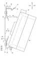
図1は、本発明の一実施形態に係るカメラユニット12の取付け状態を簡略的に示す側面図である。図1に示すように、カメラユニット12は、車両10のフロントガラス14に取り付けられる。或いは、ルーフ16にカメラユニット12を取り付けてもよい。また、カメラユニット12は、図示しないルームミラーの横に固定される。A. Embodiment 1 FIG. Explanation of overall configuration [1-1. Usage state]
FIG. 1 is a side view schematically showing a mounting state of a
なお、本実施形態のカメラユニット12は、例えば、車線からのはみ出し防止のための車線検出や先行車との距離測定に用いることができるが、その目的はこれに限らない(詳細は後述する。)。 Note that the
[1−2.全体的な構成]
図2は、正面−左側面−平面方向(X2−Y2―Z2方向)から見たカメラユニット12の斜視図である。図3は、正面−右側面−平面方向(X2−Y1―Z2方向)から見たカメラユニット12の斜視図である。図4は、カメラユニット12の背面図(X1方向)である。図5は、カメラユニット12のカメラ本体18をブラケット20に取り付ける様子を示す図である。[1-2. Overall configuration]
FIG. 2 is a perspective view of the
図1〜図3に示すように、カメラユニット12は、カメラ本体18(カメラケース)及びブラケット20を有する。ブラケット20は、カメラ本体18を着脱自在に支持しカメラ本体18を車両10(フロントガラス14)に固定する。 As shown in FIGS. 1 to 3, the
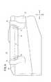
図6は、正面−左側面−平面方向(X2−Y2―Z2方向)から見たカメラ本体18の部分拡大斜視図である。図7は、正面−右側面−平面方向(X2−Y1―Z2方向)から見たカメラ本体18の部分拡大斜視図である。図8は、右側面方向(Y1方向)から見たカメラ本体18の部分拡大側面図である。 FIG. 6 is a partially enlarged perspective view of the
カメラ本体18は、前方(図1、図2等のX1方向)に進むに連れて薄くなる直方体形状を基調とし(図1参照)、その上面22の凹部24にはカメラレンズ26が配置されている。また、カメラ本体18の左側面28には、第1取付部30が形成され、カメラ本体18の右側面32には、第2取付部34が形成されている。 The
図9は、背面−右側面−底面方向(X1−Y1―Z1方向)から見たブラケット20の斜視図である。図2〜図4、図9に示すように、ブラケット20は、上側(Z1方向)の中央基部40と、左側(Y1方向)の左側面42と、右側(Y2方向)の右側面44とからなる。左側面42には、第1支持部50が形成され、右側面44には、第2支持部52が形成される。 FIG. 9 is a perspective view of the
図2〜図5等に示すように、ブラケット20の内側にカメラ本体18を挿入し、カメラ本体18の第1取付部30及び第2取付部34をブラケット20の第1支持部50及び第2支持部52に支持させることにより、カメラ本体18をブラケット20に固定する。 As shown in FIGS. 2 to 5 and the like, the
[1−3.カメラ本体18]
(1−3―1.全体構成)
上記のように、カメラ本体18は、前方(X1方向)に進むに連れて薄くなる直方体形状を基調とし(図1等参照)、その上面22には凹部24内にカメラレンズ26が配置されている。また、カメラ本体18の左側面28には、第1取付部30が形成され、カメラ本体18の右側面32には、第2取付部34が形成されている。[1-3. Camera body 18]
(1-3-1. Overall configuration)
As described above, the
(1−3−2.カメラレンズ26及び凹部24)
カメラレンズ26は、カメラ本体18の上面22において、三角錐形状を基調として形成された凹部24内に配置されている。凹部24は、カメラ本体18の視野範囲を確保するように形成されている。これにより、カメラ本体18の視野を確保しつつ、カメラ本体18の強度を確保することが可能となる。(1-3-2.
The
(1−3−3.第1取付部30)
図6には、第1取付部30及びその周辺が拡大して示されている。第1取付部30は、ブラケット20の第1支持部50に旋回可能に支持される(図5参照)。図4等に示すように、第1取付部30は、正面視及び背面視において鉤状をしている。このため、以下では、第1取付部30を鉤状部30ともいう。鉤状部30は、ブラケット20の第1支持部50の孔部60(後述)に挿入される。(1-3-3. First mounting portion 30)
FIG. 6 shows an enlarged view of the
さらに、図6等に示すように、第1取付部30には、前後方向(X1、X2方向)に延在する孔部66が形成されている。 Further, as shown in FIG. 6 and the like, the
さらにまた、図6等に示すように、カメラ本体18の左側面28には、2つの凸部62(以下「位置決め凸部62」という。)が形成されている。位置決め凸部62は、第1取付部30の両脇において外側(Y1方向)に向かって突出する。位置決め凸部62の機能については、図10を参照して後述する。 Furthermore, as shown in FIG. 6 and the like, two convex portions 62 (hereinafter referred to as “positioning
加えて、図6等に示すように、第1取付部30の孔部66には、2つの凸部64(以下「内側凸部64」という。)が形成されている。内側凸部64は、第1取付部30の先端側においてカメラ本体18の左側面28に向かって突出する。内側凸部64の機能については、図10等を参照して後述する。 In addition, as shown in FIG. 6 and the like, two protrusions 64 (hereinafter referred to as “
(1−3−4.第2取付部34)
図7及び図8には、第2取付部34及びその周辺が拡大して示されている。第2取付部34は、ブラケット20の第2支持部52に固定される。図7、図8等に示すように、第2取付部34は、係合凸部70、係合凹部72及び側方凸部74を有する。(1-3-4. Second mounting portion 34)
7 and 8 show the second mounting
係合凸部70は、下方(Z2方向)に向かうに従って外側(Y2方向)に突出する。これにより、係合凸部70の下方に係合凹部72が形成される。係合凸部70及び係合凹部72は、ブラケット20の板ばね102(後述)と係合して、ブラケット20に対してカメラ本体18を固定する(詳細は、板ばね102に関連して後述する。)。 The engaging
図8等に示すように、係合凸部70の両端には、溝76が形成されている。これにより、板ばね102を押圧位置から離間位置に移動させる際、板ばね102との接触により係合凸部70が削られることを抑制することが可能となる。 As shown in FIG. 8 and the like,
側方凸部74は、係合凸部70の両側面に配置され、板ばね102の位置ずれを防止する。図8等に示すように、側方凸部74は、上側の方が下側よりも幅広に形成されている。これにより、板ばね102の位置決めを容易化することが可能となる。 The side
[1−4.ブラケット20]
上記のように、ブラケット20は、上側の中央基部40と、中央基部40の左端から突出する左側面42と、中央基部40の右端から突出する右側面44とを有する。ブラケット20は、例えば、鉄等の金属をプレス加工等により製造する。中央基部40の外面80は、車両10(フロントガラス14)に取り付けられる取付け面として利用される(図1参照)。中央基部40の内面82は、カメラ本体18の上面22と近接する収容面として機能する。[1-4. Bracket 20]
As described above, the
(1−4−1.中央基部40)
図9等に示すように、中央基部40は、中央基部40のうち左右方向(Y1、Y2方向)の中央に位置する中央部90と、中央部90の左側に位置する左側部92と、中央部90の右側に位置する右側部94とを有する。左側部92と右側部94は、中央部90を挟んで線対称に近い形状であり、中央部90よりも前後方向(X1、X2方向)に(特に、前方向に)長い。これは、カメラ本体18の視野領域を確保するため、中央部90の長さを短くしているためである。(1-4-1. Central base 40)
As shown in FIG. 9 and the like, the
図9等に示すように、左側部92及び右側部94のそれぞれには、板ばね100、102がリベット104を介して固定される。板ばね100、102は、下方付勢部110を有する。さらに、板ばね102は、側方付勢部112を有する。 As shown in FIG. 9 and the like,
図9に示すように、板ばね100の下方付勢部110は、左側から中央に向かって(Y2方向)且つ下方(Z2方向)に向かって突出する。板ばね102の下方付勢部110は、右側から中央に向かって(Y1方向)且つ下方(Z2方向)に向かって突出する。これらにより、図4の矢印S1で示すように、各下方付勢部110は、カメラ本体18の上面22を下方向(Z2方向)に付勢する。従って、ブラケット20に対するカメラ本体18の縦方向の固定を強固にすると共に、ブラケット20に対するカメラ本体18の位置決めのばらつきを抑制することが可能となる。 As shown in FIG. 9, the downward urging
図9等に示すように、側方付勢部112は、下方付勢部110よりも外側(Y2方向)においてその主面がカメラ本体18に面する状態で下方(Z2方向)に延在する。これにより、カメラ本体18の右側面32に当接してカメラ本体18を横方向(Y1方向)に付勢する。 As shown in FIG. 9 and the like, the
図9等に示すように、側方付勢部112には、内側(Y1方向)に突出する係合凸部120が設けられている。係合凸部120は、カメラ本体18の係合凹部72(図7及び図8)と係合する。以下では、係合凸部120が係合凹部72と係合してカメラ本体18がブラケット20に固定されている際の板ばね102の位置を「押圧位置」という。 As shown in FIG. 9 and the like, the
板ばね102が押圧位置にあるとき、板ばね102の係合凸部120よりも根本側の部分が、カメラ本体18の係合凸部70に接触して図4中、左方向(Y1方向)に押圧力S2が働く。これにより、ブラケット20に対するカメラ本体18の横方向の固定を強固にすると共に、ブラケット20に対するカメラ本体18の位置決めのばらつきを抑制することが可能となる。また、カメラ本体18を板ばね102により押し付けて位置決めすることにより、車両10の走行時におけるカメラ本体18の振動を減少させ、当該振動に伴う雑音を抑制することが可能となる。 When the
一方、カメラ本体18をブラケット20から取り外す際は、作業者は、板ばね102の先端を指でつまんでカメラ本体18から離間する方向(図4のR方向)に移動させる。これにより、第2支持部52による第2取付部34の固定が解かれ、カメラ本体18は、第1取付部30を中心として旋回可能となる。その後、第1取付部30を第1支持部50から取り外すことで、カメラ本体18をブラケット20から取り外すことができる。以下では、カメラ本体18をブラケット20から取り外す際の板ばね102の位置を「離間位置」という。 On the other hand, when removing the
(1−4−2.ストッパ130)
図3、図4、図9等に示すように、板ばね102の側方付勢部112の外側(Y2方向)には、ストッパ130が設けられている。ストッパ130は、板ばね102の側方付勢部112が、カメラ本体18を取り外すための位置(離間位置)よりもさらにカメラ本体18から離間することを規制する。これにより、板ばね102が塑性変形することを防止することができる。図3、図4、図9等に示すように、ストッパ130は、ブラケット20の一部として形成され、右側部94の端部から下方(Z2方向)に向かって延在する。ブラケット20の一部として形成する代わりに、ブラケット20とは別部材としてストッパ130を設けてもよい。(1-4-2. Stopper 130)
As shown in FIGS. 3, 4, 9, and the like, a
2.取付け方法
[2−1.全体的な流れ]
次に、ブラケット20に対するカメラ本体18の取付け方法について説明する。2. Mounting method [2-1. Overall flow]
Next, a method for attaching the
図10は、底面方向(Z1方向)から見たカメラユニット12の部分拡大底面図である。ブラケット20に対してカメラ本体18を取り付ける際は、事前にブラケット20を取付け対象物(ここでは、フロントガラス14)に固定しておく。 FIG. 10 is a partially enlarged bottom view of the
そして、作業者は、ブラケット20の孔部60に対してカメラ本体18の鉤状部30を挿入する(図5等参照)。次いで、作業者は、カメラ本体18の左右が同じ高さになるように、カメラ本体18を回転させる(図5の矢印Q参照)。この際、作業者は、ブラケット20の板ばね102の側方付勢部112を外側(R方向)に指で移動させる。或いは、カメラ本体18を押し込む力により側方付勢部112を外側に移動させてもよい。 Then, the operator inserts the bowl-shaped
その後、板ばね102の係合凸部120がカメラ本体18の係合凹部72と係合すると、板ばね102からの横方向(Y1方向)の押圧力S2(図4)がカメラ本体18に加えられる。これにより、カメラ本体18が位置決めされ、ブラケット20に対して固定される。 Thereafter, when the engagement
なお、上記のように、カメラ本体18には、位置決め凸部62が形成されている(図6及び図10参照)。このため、板ばね102により付勢されたカメラ本体18は、複数の位置決め凸部62により位置決めされる。従って、カメラ本体18の光軸(X1方向)の位置決めを確実に行うことが可能となる。 As described above, the
[2−2.内側凸部64の利用方法]
上記のように、カメラ本体18をブラケット20に固定する際、カメラ本体18の鉤状部30をブラケット20の孔部60に挿入する。鉤状部30の孔部66内に形成された内側凸部64は、第1取付部30の先端側においてカメラ本体18の左側面28に向かって突出している。このため、鉤状部30を孔部60に挿入する際、第1取付部30のうち孔部60周囲の部分が、内側凸部64によって位置を規制されることとなる。[2-2. Usage of inner convex portion 64]
As described above, when the
従って、鉤状部30を孔部60に挿入する際、内側凸部64でカメラ本体18の位置決めをすると共に、その後、内側凸部64によりブラケット20との位置関係を規制しながらカメラ本体18を旋回させることができる。このため、カメラ本体18の組付けのばらつきを抑制することが可能となる。 Therefore, when inserting the bowl-shaped
3.本実施形態の効果
以上説明したように、本実施形態によれば、ブラケット20の第1支持部50にカメラ本体18の鉤状部30を引っ掛けた状態でカメラ本体18を旋回させて位置決めした後(図5参照)、ブラケット20の第2支持部52を介してカメラ本体18をブラケット20に固定することができる。これにより、カメラ本体18をスライドさせることなく、固定することが可能となり、カメラユニット12の設計自由度の向上又は省スペース化を図ることができる。3. Effects of this Embodiment As described above, according to this embodiment, after the
加えて、第1支持部50に鉤状部30を引っ掛けた状態でカメラ本体18を旋回させて位置決めした際、ブラケット20とカメラ本体18とが向き合う箇所における両者の距離(すなわち、ブラケット20の中央基部40の内面82(図9)とカメラ本体18の上面22との距離)が短くなるように設計することも可能となる。このため、さらに省スペース化を図ることができる。 In addition, when the
本実施形態において、ブラケット20の第1支持部50は、カメラ本体18の左右の一端側(左側)に対応させて配置され、第2支持部52は、カメラ本体18の左右の他端側(右側)に対応させて配置される(図4参照)。これにより、第1支持部50がカメラ本体18の前後の一端側(例えば、前側)に対応させて配置され、第2支持部52がカメラ本体18の前後の他端側(例えば、後ろ側)に対応させて配置される場合と比較してカメラ本体18の前後方向の構成を簡素化すると共に、カメラ本体18の撮像範囲に関する制約を少なくすることが可能となる。 In the present embodiment, the
本実施形態において、ブラケット20の第2支持部52は、主面がカメラ本体18に面する板ばね102を備え、板ばね102の一端は、ブラケット20(ブラケット本体)に固定され、板ばね102の他端は、通常状態においてカメラ本体18を押圧する押圧位置と、カメラ本体18を取り外す際、カメラ本体18から離間する離間位置とを切り替え可能である(図4及び図9参照)。 In the present embodiment, the
これにより、ブラケット20の第1支持部50にカメラ本体18の鉤状部30を引っ掛けた状態でカメラ本体18を旋回させて位置決めした後、板ばね102を介してカメラ本体18をブラケット20に簡易に固定することが可能となる。 Thus, after positioning the
本実施形態において、ブラケット20は、離間位置における板ばね102がカメラ本体18からさらに離間することを規制することで板ばね102が塑性変形することを防止するストッパ130(図4等)を備える。これにより、板ばね102の塑性変形を防止することが可能となる。 In the present embodiment, the
本実施形態において、ブラケット20の板ばね102は、カメラ本体18に対して突出する係合凸部120(図9)を備え、カメラ本体18は、板ばね102が押圧位置にある際、係合凸部120と係合する係合凹部72(図8)を備える。これにより、板ばね102の係合凸部120と、カメラ本体18の係合凹部72とが係合することにより、カメラ本体18をより確実にブラケット20に固定することが可能となる。 In the present embodiment, the
本実施形態において、カメラ本体18は、係合凹部72よりも板ばね102の根本側(係合凸部70)において、板ばね102の側部に対応する位置に溝76(図8)が形成される。これにより、板ばね102を押圧位置から離間位置に移動させる際、板ばね102との接触によりカメラ本体18の一部(係合凸部70)が削られることを抑制することが可能となる。 In the present embodiment, in the
本実施形態において、ブラケット20は、取付け対象物としてのフロントガラス14と接する外面80(取付け面)を有する中央基部40(基部)と、カメラ本体18の左右側面の位置に対応して中央基部40から延在する左側面42(第1側部)及び右側面44(第2側部)とを備える(図9参照)。第1支持部50は左側面42に形成され、第2支持部52は右側面44に形成され、右側面44には第2支持部52の板ばね102が配置され、カメラ本体18の左側面28(ブラケット20の左側面42に面する側面)には、ブラケット20の左側面42を位置決めする複数の位置決め凸部62(図6及び図10)が形成される。 In the present embodiment, the
これにより、ブラケット20の右側面44(第2側部)に形成された板ばね102により付勢されたカメラ本体18は、左側面42(第1側部)の複数の位置決め凸部62により位置決めされる。このため、カメラ本体18の光軸の位置決めを確実に行うことが可能となる。また、カメラ本体18を板ばね102により押し付けて位置決めすることにより、車両10の走行時におけるカメラ本体18の振動を減少させ、当該振動に伴う雑音を抑制することが可能となる。 Thus, the
本実施形態において、ブラケット20の左側面42(第1側部)には、カメラ本体18の鉤状部30を挿入する孔部60(図9)が形成され、鉤状部30の先端側には、鉤状部30の根本側に向かって突出する内側凸部64(図6及び図10)が形成される。これにより、鉤状部30を孔部60に挿入する際、内側凸部64でカメラ本体18の位置決めをすると共に、その後、内側凸部64によりブラケット20との位置関係を規制しながらカメラ本体18を旋回させることができる。このため、カメラ本体18の組付けのばらつきを抑制することが可能となる。 In the present embodiment, the left side surface 42 (first side portion) of the
B.変形例
なお、本発明は、上記実施形態に限らず、本明細書の記載内容に基づき、種々の構成を採り得ることはもちろんである。例えば、以下の構成を採用することができる。B. Modifications It should be noted that the present invention is not limited to the above-described embodiment, and it is needless to say that various configurations can be adopted based on the description of the present specification. For example, the following configuration can be adopted.
1.適用対象
上記実施形態では、カメラユニット12を車両10に適用した構成について説明したが、カメラ本体18を取り付ける構成であれば、別の対象に適用してもよい。例えば、不良品判定、寸法計測等のための画像センサとしてカメラを用いる製造装置に適用してもよい。或いは、状況確認、防犯等を目的とする監視カメラシステム等の装置又はシステムに適用することもできる。1. Application Target In the above-described embodiment, the configuration in which the
或いは、カメラユニット12に限らず、設計自由度等を考慮して、ブラケット20に着脱自在に取り付けるその他の機器に適用することも可能である。 Alternatively, the present invention is not limited to the
2.カメラ本体
上記実施形態では、カメラ本体18の形状が、前方(X1方向)に進むに連れて薄くなる直方体形状を基調としたが、例えば、第1取付部30、第2取付部34、第1支持部50及び第2支持部52を設ける観点からすれば、これに限らない。例えば、カメラ本体18の形状は、前後方向(X1、X2方向)において厚さが変化しない直方体形状を基調とすることも可能である。2. Camera body In the above embodiment, the shape of the
3.ブラケット20
上記実施形態では、ブラケット20をフロントガラス14に接着剤で固定したが、ブラケット20を取付け対象物に取り付けることができれば、これに限らない。例えば、車両10のルーフ16にボルトで固定してもよい。3.
In the said embodiment, although the
上記実施形態では、ブラケット20は、カメラ本体18の上面22、左側面28及び右側面32側からカメラ本体18を支持した。しかしながら、ブラケット20がカメラ本体18を支持する姿勢は、用途に応じて適宜変更することができる。例えば、カメラ本体18の上面22、前面36及び背面38側からカメラ本体18を支持してもよい。或いは、ブラケット20をカメラ本体18の下方に位置させる構成も可能である。 In the above embodiment, the
4.第1取付部30、第2取付部34、第1支持部50及び第2支持部52
[4−1.共通事項]
上記実施形態では、第1取付部30及び第1支持部50を左側(Y1方向)に、第2取付部34及び第2支持部52を右側(Y2方向)に配置したが、左右を反対にしてもよい。或いは、第1取付部30及び第1支持部50を前側(X1方向)に、第2取付部34及び第2支持部52を後ろ側(X2方向)に配置することも可能である。4). First mounting
[4-1. Common subject matter]
In the above embodiment, the
上記実施形態では、中央基部40の左右両端に第1支持部50及び第2支持部54を設けたが(図9参照)、例えば、第1支持部50及び第2支持部54の機能に着目すれば、第1支持部50及び第2支持部54を設ける位置は、必ずしも中央基部40の左右両端である必要はない。例えば、中央基部40の左右両端よりやや内側に第1支持部50及び第2支持部54を設けてもよい。 In the above embodiment, the
上記実施形態では、カメラ本体18の係合凸部70及び係合凹部72と板ばね102の係合凸部120とを設けたが、例えば、板ばね102によりカメラ本体18に対して横方向の押圧力(付勢力)を与える観点からすれば、これに限らない。例えば、係合凸部70を設けず、係合凹部72を周囲よりも凹ませた構成も可能である。或いは、板ばね102の押圧力が比較的強い場合、係合凸部70、係合凹部72及び係合凸部120をいずれも設けない構成も可能である。 In the above embodiment, the engagement
[4−2.第1取付部30]
上記実施形態では、第1取付部30に位置決め凸部62及び内側凸部64(図6及び図10)を設けたが、その他の機能に着目すれば、位置決め凸部62及び内側凸部64の一方又は両方を設けない構成も可能である。[4-2. First mounting portion 30]
In the above embodiment, the positioning
[4−3.第2取付部34]
上記実施形態では、係合凸部70に側方凸部74及び溝76を設けたが、その他の機能に着目すれば、側方凸部74及び溝76の一方又は両方を設けない構成も可能である。[4-3. Second mounting portion 34]
In the above embodiment, the
[4−4.第1支持部50]
上記実施形態では、第1取付部30(鉤状部30)を挿入するための孔部60(図9)を設けた。しかしながら、例えば、鉤状部30を第1支持部50に引っ掛けてカメラ本体18を旋回可能とする観点からすれば、これに限らない。例えば、孔部60を設ける代わりに、鉤状部30と係合する別の鉤状部を第1支持部50に設けることも可能である。[4-4. First support portion 50]
In the said embodiment, the hole part 60 (FIG. 9) for inserting the 1st attaching part 30 (hook-shaped part 30) was provided. However, for example, from the viewpoint of hooking the hook-shaped
[4−5.第2支持部52(板ばね102)]
上記実施形態では、カメラ本体18に対して横方向の押圧力S2(図4)を与えるために又は第2支持部52においてカメラ本体18を支持又は固定するために板ばね102を用いた。しかしながら、カメラ本体18に対して横方向の押圧力S2を与えるため又は第2支持部52においてカメラ本体18を支持又は固定するためには、その他の手段を用いることも可能である。例えば、板ばね102の代わりに図示しないボルトを横方向(Y1方向)に挿入又は螺合することでブラケット20に対してカメラ本体18を固定することも可能である。或いは、前記ボルトを螺合する代わりに、前記ボルトと図示しないコイルばねとの組合せをブラケット20に設けて横方向に前記ボルトをスライド可能とし、ブラケット20に対してカメラ本体18を固定することもできる。[4-5. Second support portion 52 (leaf spring 102)]
In the above embodiment, the
上記実施形態では、板ばね102をブラケット20(ブラケット本体)とは別部材として設けたが、ブラケット20自体を板ばねとして機能させることも可能である。 In the above embodiment, the
[4−6.ストッパ130]
上記実施形態では、板ばね102の塑性変形を防止するためのストッパ130(図4等)を設けた。しかしながら、例えば、第1取付部30(鉤状部)及び第1支持部50の構成に着目すれば、ストッパ130を設けない構成も可能である。[4-6. Stopper 130]
In the above embodiment, the stopper 130 (FIG. 4 and the like) for preventing plastic deformation of the
10…車両 12…カメラユニット
14…フロントガラス(取付け対象物) 18…カメラ本体
20…ブラケット(ブラケット本体) 30…第1取付部(鉤状部)
40…ブラケットの中央基部(基部) 42…ブラケットの左側面(第1側部)
44…ブラケットの右側面(第2側部) 50…第1支持部
52…第2支持部 60…孔部
62…位置決め凸部 64…内側凸部
72…カメラ本体の係合凹部 76…溝
80…外面(取付け面) 102…板ばね
120…板ばねの係合凸部 130…ストッパDESCRIPTION OF
40 ... Center base (base) of
44 ... right side surface (second side portion) of
Claims (7)
Translated fromJapanese前記カメラ本体は、前記ブラケットに引っ掛ける鉤状部を備え、
前記ブラケットは、
前記鉤状部を引っ掛けて前記カメラ本体を旋回可能に支持する第1支持部と、
前記カメラ本体を固定支持する第2支持部と
を備え、
前記第2支持部は、主面が前記カメラ本体に面する板ばねを備え、
前記板ばねの一端は、ブラケット本体に固定され、
前記板ばねの他端は、
通常状態において前記カメラ本体を押圧する押圧位置と、
前記カメラ本体を取り外す際、前記カメラ本体から離間する離間位置と
を切り替え可能であり、
前記ブラケットの前記板ばねは、前記カメラ本体に対して突出する係合凸部を備え、
前記カメラ本体は、前記板ばねが前記押圧位置にある際、前記係合凸部と係合する係合凹部を備え、
前記カメラ本体は、前記係合凹部よりも前記板ばねの根本側において、前記板ばねの側部に対応する位置に溝が形成される
ことを特徴とするカメラユニット。A camera unit having a camera body and a bracket for detachably supporting the camera body and fixing the camera body to an attachment object;
The camera body includes a hook-shaped portion that hooks on the bracket,
The bracket is
A first support part that hooks the hook-like part and rotatably supports the camera body;
A second support part for fixing and supporting the camera body,
The second support portion includes a leaf spring having a main surface facing the camera body,
One end of the leaf spring is fixed to the bracket body,
The other end of the leaf spring is
A pressing position for pressing the camera body in a normal state;
When removing the camera body, it is possible to switch between a separation position and a separation position away from the camera body,
The leaf spring of the bracket includes an engaging protrusion that protrudes with respect to the camera body,
The camera body includes an engagement recess that engages with the engagement protrusion when the leaf spring is in the pressed position.
It said camera body, the base side of the leaf spring than the engaging recess, a cameraunit, wherein agroove is Ruis formed at a position corresponding to the side of the plate spring.
前記カメラ本体は、前記ブラケットに引っ掛ける鉤状部を備え、
前記ブラケットは、
前記鉤状部を引っ掛けて前記カメラ本体を旋回可能に支持する第1支持部と、
前記カメラ本体を固定支持する第2支持部と
を備え、
前記第2支持部は、主面が前記カメラ本体に面する板ばねを備え、
前記板ばねの一端は、ブラケット本体に固定され、
前記板ばねの他端は、
通常状態において前記カメラ本体を押圧する押圧位置と、
前記カメラ本体を取り外す際、前記カメラ本体から離間する離間位置と
を切り替え可能であり、
前記ブラケットの前記板ばねは、前記カメラ本体に対して突出する係合凸部を備え、
前記カメラ本体は、前記板ばねが前記押圧位置にある際、前記係合凸部と係合する係合凹部を備え、
前記ブラケットは、前記取付け対象物と接する取付け面を有する基部と、
前記カメラ本体の左右側面の位置に対応して前記基部から延在する第1側部及び第2側部と
を備え、
前記第1支持部は前記第1側部として形成され、
前記第2支持部は前記第2側部として形成され、
前記第2側部には前記第2支持部の前記板ばねが配置され、
前記カメラ本体のうち前記第1側部に面する側面には、前記第1側部を位置決めする複数の位置決め凸部が形成され、
複数の前記位置決め凸部は、前記鉤状部とは別に設けられている
ことを特徴とするカメラユニット。A camera unit having a camera body and a bracket for detachably supporting the camera body and fixing the camera body to an attachment object;
The camera body includes a hook-shaped portion that hooks on the bracket,
The bracket is
A first support part that hooks the hook-like part and rotatably supports the camera body;
A second support part for fixing and supporting the camera body,
The second support portionbefore SL hasa leaf spring main surface facing the camera body,
One end of the leaf spring is fixed to the bracket body,
The other end of the leaf spring is
A pressing position for pressing the camera body in a normal state;
When removing the camera body, a separation position away from the camera body;
Can be switched,
The leaf spring of the bracket includes an engaging protrusion that protrudes with respect to the camera body,
The camera body includes an engagement recess that engages with the engagement protrusion when the leaf spring is in the pressed position.
The bracket has a base portion having an attachment surface in contact with the attachment object;
A first side and a second side extending from the base corresponding to the positions of the left and right side surfaces of the camera body;
With
The first support portion is formed as the first side portion;
The second support part is formed as the second side part;
The leaf spring of the second support part is disposed on the second side part,
A plurality of positioning projections for positioning the first side part are formed on a side surface of the camera body facing the first side part,
The camera unit, wherein the plurality of positioning protrusions are provided separately from the bowl-shaped portion .
前記カメラ本体は、前記ブラケットに引っ掛ける鉤状部を備え、
前記ブラケットは、
前記鉤状部を引っ掛けて前記カメラ本体を旋回可能に支持する第1支持部と、
前記カメラ本体を固定支持する第2支持部と
を備え、
前記第2支持部は、主面が前記カメラ本体に面する板ばねを備え、
前記板ばねの一端は、ブラケット本体に固定され、
前記板ばねの他端は、
通常状態において前記カメラ本体を押圧する押圧位置と、
前記カメラ本体を取り外す際、前記カメラ本体から離間する離間位置と
を切り替え可能であり、
前記ブラケットの前記板ばねは、前記カメラ本体に対して突出する係合凸部を備え、
前記カメラ本体は、前記板ばねが前記押圧位置にある際、前記係合凸部と係合する係合凹部を備え、
前記ブラケットは、前記取付け対象物と接する取付け面を有する基部と、
前記カメラ本体の左右側面の位置に対応して前記基部から延在する第1側部及び第2側部と
を備え、
前記第1支持部は前記第1側部として形成され、
前記第2支持部は前記第2側部として形成され、
前記ブラケットの前記第1側部には、前記カメラ本体の前記鉤状部を挿入する孔部が形成され、
前記鉤状部の先端側には、前記鉤状部の根本側に向かって突出する内側凸部が形成される
ことを特徴とするカメラユニット。A camera unit having a camera body and a bracket for detachably supporting the camera body and fixing the camera body to an attachment object;
The camera body includes a hook-shaped portion that hooks on the bracket,
The bracket is
A first support part that hooks the hook-like part and rotatably supports the camera body;
A second support portion for fixing and supporting the camera body;
With
The second support portion includes a leaf spring having a main surface facing the camera body,
One end of the leaf spring is fixed to the bracket body,
The other end of the leaf spring is
A pressing position for pressing the camera body in a normal state;
When removing the camera body, a separation position away from the camera body;
Can be switched,
The leaf spring of the bracket includes an engaging protrusion that protrudes with respect to the camera body,
The camera body includes an engagement recess that engages with the engagement protrusion when the leaf spring is in the pressed position.
The bracket has a base portion having an attachment surface in contact with the attachment object;
A first side and a second side extending from the base corresponding to the positions of the left and right side surfaces of the camera body;
With
The first support portion is formed as the first side portion;
The second support part is formed as the second side part;
The first side portion of the bracket is formed with a hole for inserting the bowl-shaped portion of the camera body,
The camera unit accordingto claim 1, wherein an inner convex portion that protrudes toward a base side of the hook-shaped portion is formed on a tip side of the hook-shaped portion .
前記ブラケットは、前記離間位置における前記板ばねが前記カメラ本体からさらに離間することを規制することで前記板ばねが塑性変形することを防止するストッパを備える
ことを特徴とするカメラユニット。The camera unit accordingto any one of claims 1to 3,
The bracket includes a stopper that prevents the plate spring from being plastically deformed by restricting further separation of the plate spring from the camera body at the separated position.
前記カメラ本体は、前記係合凹部よりも前記板ばねの根本側において、前記板ばねの側部に対応する位置に溝が形成される
ことを特徴とするカメラユニット。The camera unit accordingto claim2 or 3 ,
The camera body is characterized in that a groove is formed at a position corresponding to a side portion of the leaf spring on a base side of the leaf spring with respect to the engagement recess.
前記ブラケットは、前記取付け対象物と接する取付け面を有する基部と、
前記カメラ本体の左右側面の位置に対応して前記基部から延在する第1側部及び第2側部と
を備え、
前記第1支持部は前記第1側部として形成され、
前記第2支持部は前記第2側部として形成され、
前記第2側部には前記第2支持部の前記板ばねが配置され、
前記カメラ本体のうち前記第1側部に面する側面には、前記第1側部を位置決めする複数の位置決め凸部が形成される
ことを特徴とするカメラユニット。In claim1 Symbol placement of the camera unit,
The bracket has a base portion having an attachment surface in contact with the attachment object;
A first side and a second side extending from the base corresponding to the positions of the left and right side surfaces of the camera body,
The first support portion is formed as the first side portion;
The second support part is formed as the second side part;
The leaf spring of the second support part is disposed on the second side part,
A camera unit, wherein a plurality of positioning protrusions for positioning the first side portion are formed on a side surface of the camera body facing the first side portion.
前記ブラケットの前記第1側部には、前記カメラ本体の前記鉤状部を挿入する孔部が形成され、
前記鉤状部の先端側には、前記鉤状部の根本側に向かって突出する内側凸部が形成される
ことを特徴とするカメラユニット。
The camera unit accordingto claim2 or 6 ,
The first side portion of the bracket is formed with a hole for inserting the bowl-shaped portion of the camera body,
The camera unit according to claim 1, wherein an inner convex portion that protrudes toward a base side of the hook-shaped portion is formed on a distal end side of the hook-shaped portion.
Priority Applications (3)
| Application Number | Priority Date | Filing Date | Title |
|---|---|---|---|
| JP2013152423AJP5947759B2 (en) | 2013-07-23 | 2013-07-23 | Camera unit |
| CA2857296ACA2857296C (en) | 2013-07-23 | 2014-07-21 | Camera unit |
| US14/337,289US8944705B1 (en) | 2013-07-23 | 2014-07-22 | Camera unit |
Applications Claiming Priority (1)
| Application Number | Priority Date | Filing Date | Title |
|---|---|---|---|
| JP2013152423AJP5947759B2 (en) | 2013-07-23 | 2013-07-23 | Camera unit |
Publications (2)
| Publication Number | Publication Date |
|---|---|
| JP2015020695A JP2015020695A (en) | 2015-02-02 |
| JP5947759B2true JP5947759B2 (en) | 2016-07-06 |
Family
ID=52390625
Family Applications (1)
| Application Number | Title | Priority Date | Filing Date |
|---|---|---|---|
| JP2013152423AExpired - Fee RelatedJP5947759B2 (en) | 2013-07-23 | 2013-07-23 | Camera unit |
Country Status (3)
| Country | Link |
|---|---|
| US (1) | US8944705B1 (en) |
| JP (1) | JP5947759B2 (en) |
| CA (1) | CA2857296C (en) |
Families Citing this family (53)
| Publication number | Priority date | Publication date | Assignee | Title |
|---|---|---|---|---|
| DE102012101781B4 (en)* | 2012-03-02 | 2014-07-10 | Continental Automotive Gmbh | Support frame for sensor devices in vehicles |
| WO2014035958A1 (en)* | 2012-08-27 | 2014-03-06 | Gentex Corporation | Mirror mounting assembly |
| JP5880468B2 (en)* | 2013-02-05 | 2016-03-09 | マツダ株式会社 | Dropout structure for vehicle operation switch |
| US9487161B2 (en) | 2013-10-04 | 2016-11-08 | Magna Mirrors Of America, Inc. | Accessory system for a vehicle |
| JP6172174B2 (en)* | 2015-02-06 | 2017-08-02 | トヨタ自動車株式会社 | Vehicle front information acquisition device |
| JP6308147B2 (en)* | 2015-03-05 | 2018-04-11 | トヨタ自動車株式会社 | In-vehicle sensor mounting structure |
| JP2016187988A (en)* | 2015-03-30 | 2016-11-04 | ダイハツ工業株式会社 | Mounting device of on-vehicle equipment |
| JP6392267B2 (en)* | 2016-03-24 | 2018-09-19 | 本田技研工業株式会社 | Sensor bracket |
| JP6307545B2 (en)* | 2016-03-24 | 2018-04-04 | 本田技研工業株式会社 | Sensor bracket |
| JP6316329B2 (en)* | 2016-03-24 | 2018-04-25 | 本田技研工業株式会社 | Sensor bracket |
| JP2017171137A (en)* | 2016-03-24 | 2017-09-28 | ソニー株式会社 | Imaging unit support device |
| EP3436352B1 (en)* | 2016-04-01 | 2021-03-31 | B/E Aerospace, Inc. | Hinge for enlarging the volume of an aircraft storage bin |
| JP6767186B2 (en)* | 2016-07-20 | 2020-10-14 | 日野自動車株式会社 | In-vehicle camera device |
| JP6494569B2 (en) | 2016-07-20 | 2019-04-03 | 株式会社ニフコ | Camera unit |
| US10099629B2 (en)* | 2016-09-06 | 2018-10-16 | Huf North America Automotive Parts Manufacturing Corp. | Deployable sensor assembly |
| US10268038B2 (en) | 2016-09-16 | 2019-04-23 | Methode Electronics, Inc. | Camera lens washing device |
| US10422992B2 (en) | 2016-09-16 | 2019-09-24 | Methode Electronics, Inc. | Camera lens washing device |
| US10391523B2 (en) | 2016-09-16 | 2019-08-27 | Methode Electronics, Inc. | Sensor washing device |
| US10682988B2 (en) | 2016-09-16 | 2020-06-16 | Methode Electronics, Inc. | Enhanced washing device for vehicle accessory |
| JP6683818B2 (en) | 2016-09-21 | 2020-04-22 | 日立オートモティブシステムズ株式会社 | Imaging device |
| WO2018138773A1 (en)* | 2017-01-24 | 2018-08-02 | 三菱電機株式会社 | Protrusion drop structure and electronic apparatus having protrusion drop structure |
| JP6988409B2 (en)* | 2017-04-03 | 2022-01-05 | 株式会社デンソー | The camera module |
| CN107031519B (en)* | 2017-05-27 | 2023-09-01 | 观致汽车有限公司 | Sensor safety support for vehicle and anti-collision beam assembly and vehicle comprising same |
| EP3668754B1 (en) | 2017-08-15 | 2021-09-22 | Methode Electronics, Inc. | Locking bracket for vehicle accessory |
| US10527910B2 (en)* | 2017-08-29 | 2020-01-07 | Trw Automotive U.S. Llc | Vehicle driver assist system |
| EP3461689B1 (en)* | 2017-09-27 | 2020-12-16 | Continental Automotive GmbH | Camera device and method for mounting a camera device for a motor vehicle |
| US10190610B1 (en) | 2017-10-13 | 2019-01-29 | Gentex Corporation | Mounting assembly for rearview device |
| JP6948591B2 (en)* | 2017-10-23 | 2021-10-13 | いすゞ自動車株式会社 | Mounting structure of in-vehicle parts |
| DE212018000374U1 (en) | 2017-12-08 | 2020-07-08 | Gentex Corporation | Preloaded two-leaf torsion spring assembly for rear view devices |
| US10974650B2 (en) | 2017-12-11 | 2021-04-13 | Gentex Corporation | Rearview device mount and attachment method |
| CN109058739B (en)* | 2018-09-12 | 2020-02-18 | 张桓毓 | Portable split type supporting and fixing device based on Internet of things |
| JP6995733B2 (en)* | 2018-12-07 | 2022-01-17 | 本田技研工業株式会社 | Detection device |
| JP6995734B2 (en)* | 2018-12-07 | 2022-01-17 | 本田技研工業株式会社 | Detection device |
| JP6726265B2 (en) | 2018-12-18 | 2020-07-22 | 本田技研工業株式会社 | Sensor bracket |
| JP7048479B2 (en) | 2018-12-18 | 2022-04-05 | 本田技研工業株式会社 | Transport equipment and sensor brackets |
| JP7042206B2 (en)* | 2018-12-18 | 2022-03-25 | 本田技研工業株式会社 | Transport equipment and sensor brackets |
| EP4275962B1 (en)* | 2018-12-28 | 2024-12-04 | ZF Active Safety and Electronics US LLC | Driver assist system |
| JP7002485B2 (en)* | 2019-02-08 | 2022-02-10 | 株式会社ニフコ | Bracket for in-vehicle camera |
| JP7147613B2 (en)* | 2019-02-14 | 2022-10-05 | トヨタ自動車株式会社 | Camera mounting structure |
| US11433827B2 (en)* | 2019-06-07 | 2022-09-06 | Volvo Car Corporation | Bracket assembly for securing a safety equipment module to a windowpane of a vehicle |
| US11338742B2 (en)* | 2019-07-25 | 2022-05-24 | Nifco Inc. | Bracket for in-vehicle device and holding device for in-vehicle device |
| DE102019215667B3 (en) | 2019-10-11 | 2020-11-05 | Continental Automotive Gmbh | Device for fastening an optical device |
| CN112672003A (en)* | 2019-10-15 | 2021-04-16 | 维沃移动通信有限公司 | Camera module, electronic equipment and equipment assembly |
| CA3177455A1 (en)* | 2020-05-20 | 2021-11-25 | Technologies Cgc Inc. | Brackets for portable equipment |
| WO2022052057A1 (en)* | 2020-09-11 | 2022-03-17 | 深圳市大疆创新科技有限公司 | Vehicle-mounted multi-view structure and vehicle |
| CN112610824B (en)* | 2020-12-18 | 2022-07-15 | 江西精达金属设备有限公司 | Support device for security and protection equipment |
| FR3117961B1 (en)* | 2020-12-18 | 2024-07-19 | Renault Sas | Support device comprising a removable window camera stop member |
| JP7199463B2 (en)* | 2021-03-30 | 2023-01-05 | 本田技研工業株式会社 | Mounting structure of external detection sensor for vehicle |
| JP7639613B2 (en)* | 2021-08-20 | 2025-03-05 | トヨタ自動車株式会社 | Vehicle-mounted camera fixing structure |
| TWI789085B (en)* | 2021-10-28 | 2023-01-01 | 群光電子股份有限公司 | Hanging device |
| FR3129640A1 (en)* | 2021-11-26 | 2023-06-02 | Psa Automobiles Sa | Support intended for fixing a telematics module to an internal structural element of a motor vehicle, telematics system and vehicle comprising such a support |
| JP7733621B2 (en)* | 2022-08-01 | 2025-09-03 | 株式会社ニフコ | Brackets for automotive equipment |
| WO2024154648A1 (en)* | 2023-01-18 | 2024-07-25 | 株式会社ヨコオ | Onboard device, onboard device set, vehicle-side mounted part, and vehicle-side connection part |
Family Cites Families (12)
| Publication number | Priority date | Publication date | Assignee | Title |
|---|---|---|---|---|
| US3291179A (en)* | 1964-02-17 | 1966-12-13 | Eastman Kodak Co | Camera carrying case |
| JPS4621445Y1 (en)* | 1968-08-31 | 1971-07-24 | ||
| US4536925A (en)* | 1983-10-11 | 1985-08-27 | Motorola, Inc. | Belt clip assembly with a controlled failure mode |
| JPH0413875Y2 (en)* | 1986-08-01 | 1992-03-30 | ||
| JPH05167657A (en)* | 1991-12-12 | 1993-07-02 | Matsushita Electric Ind Co Ltd | Support device for on-vehicle telephone set |
| JP2002341432A (en)* | 2001-05-16 | 2002-11-27 | Murakami Corp | Imaging device |
| DE102008044839A1 (en)* | 2008-08-28 | 2010-03-04 | Leopold Kostal Gmbh & Co. Kg | Sensor arrangement for a motor vehicle |
| JP5704886B2 (en)* | 2010-10-25 | 2015-04-22 | 日本電産エレシス株式会社 | In-vehicle camera mounting structure |
| US8827574B2 (en)* | 2010-11-03 | 2014-09-09 | Joseph M. Johnson | Camera mounting assembly |
| JP5316562B2 (en)* | 2011-02-10 | 2013-10-16 | 株式会社デンソー | Car camera |
| JP5946295B2 (en) | 2012-03-08 | 2016-07-06 | 本田技研工業株式会社 | Camera unit |
| JP5761100B2 (en)* | 2012-03-28 | 2015-08-12 | 株式会社デンソー | Car camera |
- 2013
- 2013-07-23JPJP2013152423Apatent/JP5947759B2/ennot_activeExpired - Fee Related
- 2014
- 2014-07-21CACA2857296Apatent/CA2857296C/ennot_activeExpired - Fee Related
- 2014-07-22USUS14/337,289patent/US8944705B1/enactiveActive
Also Published As
| Publication number | Publication date |
|---|---|
| US8944705B1 (en) | 2015-02-03 |
| CA2857296A1 (en) | 2015-01-23 |
| CA2857296C (en) | 2016-08-23 |
| JP2015020695A (en) | 2015-02-02 |
| US20150030319A1 (en) | 2015-01-29 |
Similar Documents
| Publication | Publication Date | Title |
|---|---|---|
| JP5947759B2 (en) | Camera unit | |
| JP6052246B2 (en) | In-vehicle camera mounting structure | |
| US10336264B2 (en) | In-vehicle camera | |
| US10272849B2 (en) | In-vehicle camera attached to windshield forming inhibition space therebetween | |
| CN111565267B (en) | Camera assembling structure | |
| JP6276964B2 (en) | Radiator grill | |
| JP2012091596A (en) | Onboard structure of camera | |
| US20130291418A1 (en) | Marking Carrier for Marking a Floating Caliper Brake | |
| JP2010083464A (en) | In-vehicle device and holding member | |
| JP6796192B2 (en) | Imaging device | |
| JP7045695B2 (en) | Car smartphone holder | |
| JP6147180B2 (en) | Ultrasonic sensor module mounting structure | |
| JP6624509B2 (en) | In-vehicle camera mounting structure | |
| JP2008195087A (en) | Door mirror | |
| WO2017002191A1 (en) | Electronic control unit bracket and vehicle | |
| JP2016150723A (en) | Vehicle room mirror | |
| JP4859246B2 (en) | Vehicle lamp | |
| JP2017114465A (en) | Mounting tool of on-vehicle electrical component | |
| JP2017105418A (en) | Fitting tool for on-vehicle electrical component | |
| JP2011111146A (en) | Mounting structure of audio for automobile | |
| JP2016060278A (en) | Inner mirror structure for vehicles | |
| WO2022113454A1 (en) | Information acquisition device attachment unit | |
| JP5704511B2 (en) | Mounting structure for in-vehicle equipment | |
| JP2014043158A (en) | License plate mounting structure in vehicle | |
| JP2013163481A (en) | Door mirror device for vehicle |
Legal Events
| Date | Code | Title | Description |
|---|---|---|---|
| A977 | Report on retrieval | Free format text:JAPANESE INTERMEDIATE CODE: A971007 Effective date:20150422 | |
| A131 | Notification of reasons for refusal | Free format text:JAPANESE INTERMEDIATE CODE: A131 Effective date:20150507 | |
| A521 | Request for written amendment filed | Free format text:JAPANESE INTERMEDIATE CODE: A523 Effective date:20150701 | |
| A131 | Notification of reasons for refusal | Free format text:JAPANESE INTERMEDIATE CODE: A131 Effective date:20160202 | |
| A521 | Request for written amendment filed | Free format text:JAPANESE INTERMEDIATE CODE: A523 Effective date:20160325 | |
| TRDD | Decision of grant or rejection written | ||
| A01 | Written decision to grant a patent or to grant a registration (utility model) | Free format text:JAPANESE INTERMEDIATE CODE: A01 Effective date:20160531 | |
| A61 | First payment of annual fees (during grant procedure) | Free format text:JAPANESE INTERMEDIATE CODE: A61 Effective date:20160603 | |
| R150 | Certificate of patent or registration of utility model | Ref document number:5947759 Country of ref document:JP Free format text:JAPANESE INTERMEDIATE CODE: R150 | |
| LAPS | Cancellation because of no payment of annual fees |