JP5945653B1 - Solid-state imaging device and electronic endoscope provided with the solid-state imaging device - Google Patents
Solid-state imaging device and electronic endoscope provided with the solid-state imaging deviceDownload PDFInfo
- Publication number
- JP5945653B1 JP5945653B1JP2016506011AJP2016506011AJP5945653B1JP 5945653 B1JP5945653 B1JP 5945653B1JP 2016506011 AJP2016506011 AJP 2016506011AJP 2016506011 AJP2016506011 AJP 2016506011AJP 5945653 B1JP5945653 B1JP 5945653B1
- Authority
- JP
- Japan
- Prior art keywords
- imaging device
- core wire
- circuit board
- solid
- outer conductor
- Prior art date
- Legal status (The legal status is an assumption and is not a legal conclusion. Google has not performed a legal analysis and makes no representation as to the accuracy of the status listed.)
- Active
Links
Images


Classifications
- A—HUMAN NECESSITIES
- A61—MEDICAL OR VETERINARY SCIENCE; HYGIENE
- A61B—DIAGNOSIS; SURGERY; IDENTIFICATION
- A61B1/00—Instruments for performing medical examinations of the interior of cavities or tubes of the body by visual or photographical inspection, e.g. endoscopes; Illuminating arrangements therefor
- A61B1/04—Instruments for performing medical examinations of the interior of cavities or tubes of the body by visual or photographical inspection, e.g. endoscopes; Illuminating arrangements therefor combined with photographic or television appliances
- A61B1/05—Instruments for performing medical examinations of the interior of cavities or tubes of the body by visual or photographical inspection, e.g. endoscopes; Illuminating arrangements therefor combined with photographic or television appliances characterised by the image sensor, e.g. camera, being in the distal end portion
- A61B1/051—Details of CCD assembly
- A—HUMAN NECESSITIES
- A61—MEDICAL OR VETERINARY SCIENCE; HYGIENE
- A61B—DIAGNOSIS; SURGERY; IDENTIFICATION
- A61B1/00—Instruments for performing medical examinations of the interior of cavities or tubes of the body by visual or photographical inspection, e.g. endoscopes; Illuminating arrangements therefor
- A61B1/04—Instruments for performing medical examinations of the interior of cavities or tubes of the body by visual or photographical inspection, e.g. endoscopes; Illuminating arrangements therefor combined with photographic or television appliances
- G—PHYSICS
- G02—OPTICS
- G02B—OPTICAL ELEMENTS, SYSTEMS OR APPARATUS
- G02B23/00—Telescopes, e.g. binoculars; Periscopes; Instruments for viewing the inside of hollow bodies; Viewfinders; Optical aiming or sighting devices
- G02B23/24—Instruments or systems for viewing the inside of hollow bodies, e.g. fibrescopes
- G02B23/2476—Non-optical details, e.g. housings, mountings, supports
- G02B23/2484—Arrangements in relation to a camera or imaging device
- H—ELECTRICITY
- H04—ELECTRIC COMMUNICATION TECHNIQUE
- H04N—PICTORIAL COMMUNICATION, e.g. TELEVISION
- H04N23/00—Cameras or camera modules comprising electronic image sensors; Control thereof
- H04N23/50—Constructional details
- H04N23/54—Mounting of pick-up tubes, electronic image sensors, deviation or focusing coils
- H—ELECTRICITY
- H04—ELECTRIC COMMUNICATION TECHNIQUE
- H04N—PICTORIAL COMMUNICATION, e.g. TELEVISION
- H04N23/00—Cameras or camera modules comprising electronic image sensors; Control thereof
- H04N23/50—Constructional details
- H04N23/555—Constructional details for picking-up images in sites, inaccessible due to their dimensions or hazardous conditions, e.g. endoscopes or borescopes
- G—PHYSICS
- G02—OPTICS
- G02B—OPTICAL ELEMENTS, SYSTEMS OR APPARATUS
- G02B23/00—Telescopes, e.g. binoculars; Periscopes; Instruments for viewing the inside of hollow bodies; Viewfinders; Optical aiming or sighting devices
- G02B23/24—Instruments or systems for viewing the inside of hollow bodies, e.g. fibrescopes
- G02B23/26—Instruments or systems for viewing the inside of hollow bodies, e.g. fibrescopes using light guides
Landscapes
- Physics & Mathematics (AREA)
- Health & Medical Sciences (AREA)
- Life Sciences & Earth Sciences (AREA)
- Engineering & Computer Science (AREA)
- Surgery (AREA)
- Optics & Photonics (AREA)
- Multimedia (AREA)
- Medical Informatics (AREA)
- Molecular Biology (AREA)
- Nuclear Medicine, Radiotherapy & Molecular Imaging (AREA)
- Pathology (AREA)
- Radiology & Medical Imaging (AREA)
- Astronomy & Astrophysics (AREA)
- Biomedical Technology (AREA)
- Heart & Thoracic Surgery (AREA)
- General Physics & Mathematics (AREA)
- Biophysics (AREA)
- Animal Behavior & Ethology (AREA)
- General Health & Medical Sciences (AREA)
- Public Health (AREA)
- Veterinary Medicine (AREA)
- Signal Processing (AREA)
- Endoscopes (AREA)
- Instruments For Viewing The Inside Of Hollow Bodies (AREA)
- Studio Devices (AREA)
Abstract
Translated fromJapaneseDescription
Translated fromJapanese本発明は、電子内視鏡の挿入部の先端部に配設される固体撮像装置に関する。 The present invention relates to a solid-state imaging device disposed at a distal end portion of an insertion portion of an electronic endoscope.
生体の体内や構造物の内部などの観察が困難な箇所を観察するために、生体や構造物の外部から内部に導入可能であって、光学像を撮像するための固体撮像装置である撮像ユニットなどを具備した電子内視鏡が、例えば医療分野または工業分野において利用されている。 An imaging unit that is a solid-state imaging device that can be introduced into the living body or structure from the outside to observe an area that is difficult to observe, such as the inside of a living body or the inside of a structure, and that captures an optical image An electronic endoscope equipped with the above is used in, for example, the medical field or the industrial field.
電子内視鏡の撮像ユニットは、被写体像を結像する対物レンズと、対物レンズの結像面に配設された一般にCCD(電荷結合素子)、CMOS(相補型金属酸化膜半導体)センサなどの撮像素子を具備している。 An imaging unit of an electronic endoscope includes an objective lens that forms a subject image, and a CCD (Charge Coupled Device), a CMOS (Complementary Metal Oxide Semiconductor) sensor, etc. that are generally disposed on the imaging surface of the objective lens. An image sensor is provided.
このような電子内視鏡は、例えば、日本国特開2005−304876号公報に開示されるような撮像ユニットが知られている。この従来の電子内視鏡の撮像ユニットは、複数の同軸信号線の外部導体がグランド用ジャンパ線に巻き付けられて回路基板へ接続された構成となっている。 As such an electronic endoscope, for example, an imaging unit disclosed in Japanese Patent Application Laid-Open No. 2005-304876 is known. This conventional imaging unit of an electronic endoscope has a configuration in which outer conductors of a plurality of coaxial signal lines are wound around a ground jumper line and connected to a circuit board.
ところで、近年の電子内視鏡では、被検体への挿入性向上のため、挿入部の細径化および短縮化が要求され、これに伴い撮像ユニットの小型化も要求されている。 By the way, in recent electronic endoscopes, in order to improve insertability into a subject, it is required to reduce the diameter and shorten the insertion portion, and accordingly, downsizing of the imaging unit is also required.
しかしながら、従来の撮像ユニットでは、複数の同軸信号線のシールドが束ねられたシールド束がグランド用ジャンパ線を介して回路基板へ電気的に接続されるため、積層基板の長手方向の短縮化を阻害するばかりでなく、外部導体の結束部が外径方向に膨らんで細径化も阻害するという課題があった。 However, in the conventional imaging unit, since the shield bundle in which the shields of a plurality of coaxial signal lines are bundled is electrically connected to the circuit board through the ground jumper wire, the longitudinal shortening of the multilayer substrate is hindered. In addition, there is a problem in that the binding portion of the outer conductor swells in the outer diameter direction and inhibits the diameter reduction.
このように、撮像ユニットの小型化が阻害されると、撮像ユニットが内蔵される挿入部の先端部が長くなると共に外径が大きくなってしまい、挿入部の細径化を阻害するばかりでなく、硬質長が延びるため挿入性を低下させる要因となっていた。 As described above, when the downsizing of the imaging unit is hindered, the distal end portion of the insertion portion in which the imaging unit is incorporated becomes longer and the outer diameter becomes larger, which not only prevents the insertion portion from being reduced in diameter. In addition, since the hard length is extended, it has been a factor of lowering the insertability.
そこで、本発明は、上述した事情に鑑みてなされたものであって、挿入部の細径化および硬質長の短縮化に寄与する小型な固体撮像装置およびこの固体撮像装置を備えた電子内視鏡を提供することを目的とする。 Accordingly, the present invention has been made in view of the above-described circumstances, and is a compact solid-state imaging device that contributes to reducing the diameter of the insertion portion and shortening the hard length, and an electronic endoscope including the solid-state imaging device. The purpose is to provide a mirror.
本発明の一態様の固体撮像装置は、撮像素子と、前記撮像素子に電気的に接続されたフレキシブルプリント基板と、前記撮像素子の背面に接着されると共に、前記フレキシブルプリント基板に電気的に接続された硬質基板と、複数の同軸線を内蔵する信号ケーブルと、を有する固体撮像装置において、前記硬質基板は、前記同軸線の芯線が接続される芯線接続部を有する第1の面と、前記同軸線の外部導体が接続される外部導体接続部を有し、前記第1の面と略平行な第2の面と、を備え、前記第2の面は、前記第1の面に対して段差を有し、前記段差の高さ寸法は、前記同軸線の前記芯線の外径部と前記外部導体の外径部の寸法差と略同一であり、前記第1の面と前記第2の面は、前記硬質基板の少なくとも表面と裏面とに形成され、前記複数の同軸線が前記硬質基板の前記第1および第2の面に対して略平行に接続されている。The solid-state imaging device of one embodiment of the present invention, ashooting image element,and the flexible printed circuit board which is electrically connected to the imaging device,while being adhered to the back of the imagingdevice, electrically tothe flexible printed circuit board in the solid-state imaging device having aconnected hard substrate, and a signal cable that incorporates aplurality of coaxial lines, wherein the rigid substrate includes a first surface having a core wire connection portion core wire of the coaxial line is connected, An outer conductor connecting portion to which the outer conductor of the coaxial line is connected, and a second surface substantially parallel to the first surface,wherein the second surface is relative tothe first surface The height of the step is substantially the same as the dimensional difference between the outer diameter portion of the core wire and the outer diameter portion of the outer conductor of the coaxial line, and the first surface and the second surface is formed on at least a front surface and a back surface of the hard substrate, wherein Are substantially parallel to connection with respect tothe number of the coaxial line is the first and second surfaces of the rigid substrate.
本発明の一態様の電子内視鏡は、撮像素子と、前記撮像素子に電気的に接続されたフレキシブルプリント基板と、前記撮像素子の背面に接着されると共に、前記フレキシブルプリント基板に電気的に接続された硬質基板と、複数の同軸線を内蔵する信号ケーブルと、を有する固体撮像装置において、前記硬質基板は、前記同軸線の芯線が接続される芯線接続部を有する第1の面と、前記同軸線の外部導体が接続される外部導体接続部を有し、前記第1の面と略平行な第2の面と、を備え、前記第2の面は、前記第1の面に対して段差を有し、前記段差の高さ寸法は、前記同軸線の前記芯線の外径部と前記外部導体の外径部の寸法差と略同一であり、前記第1の面と前記第2の面は、前記硬質基板の少なくとも表面と裏面とに形成され、前記複数の同軸線が前記硬質基板の前記第1および第2の面に対して略平行に接続されている固体撮像装置と、前記固体撮像装置が先端部内に内蔵された挿入部と、を具備し、前記信号ケーブルが前記挿入部の長手方向に略平行に配置されている。The electronic endoscope of one embodiment of the present invention, ashooting image element,and the flexible printed circuit board which is electrically connected to the imaging device,while being adhered to the back of the imagingdevice, electrically tothe flexible printed circuit board In the solid-state imaging device having a hard substrate connectedto the signal line and a signal cable incorporating aplurality of coaxial lines, the hard substrate has a first surface having a core wire connection portion to which the core wire of the coaxial line is connected. And an outer conductor connecting portion to which an outer conductor of the coaxial line is connected, and a second surface substantially parallel to the first surface,wherein the second surface is on the first surface. The height of the step is substantially the same as the dimensional difference between the outer diameter portion of the core wire and the outer diameter portion of the outer conductor of the coaxial line, and the first surface and the first second surface is formed on at least a front surface and a back surface of the hard substrate, thedouble Coaxial line anda substantially a solid-state imaging device that is connected in parallel, thesolid insertion portion by the imagingdevice is incorporated in the distal end portion relative to said first and second surfaces of the rigidsubstrate, The signal cable is disposed substantially parallel to the longitudinal direction of the insertion portion.
以上に記載の本発明によれば、挿入部の先端の細径化および硬質長の短縮化に寄与する小型な固体撮像装置およびこの固体撮像装置を備えた電子内視鏡を提供できる。 According to the present invention described above, it is possible to provide a small solid-state imaging device that contributes to reducing the diameter of the distal end of the insertion portion and shortening the rigid length, and an electronic endoscope including the solid-state imaging device.
以下に、本発明の好ましい形態について図面を参照して説明する。なお、以下の説明に用いる各図においては、各構成要素を図面上で認識可能な程度の大きさとするため、構成要素毎に縮尺を異ならせてあるものであり、本発明は、これらの図に記載された構成要素の数量、構成要素の形状、構成要素の大きさの比率、および各構成要素の相対的な位置関係のみに限定されるものではない。また、以下の説明においては、図の紙面に向かって見た上下方向を構成要素の上部および下部、構成要素の内側方向を外形中心方向などとして説明している場合がある。 Hereinafter, preferred embodiments of the present invention will be described with reference to the drawings. In the drawings used for the following description, the scale of each component is made different in order to make each component recognizable on the drawing. It is not limited only to the quantity of the component described in (1), the shape of the component, the ratio of the size of the component, and the relative positional relationship of each component. Further, in the following description, there are cases in which the up and down direction as viewed toward the page of the drawing is described as the upper and lower parts of the component, and the inner direction of the component is the outer center direction.
先ず、本発明の一態様の固体撮像装置としての撮像ユニットおよび電子内視鏡について、図面に基づいて、以下に説明する。 First, an imaging unit and an electronic endoscope as a solid-state imaging device of one embodiment of the present invention are described below with reference to the drawings.
なお、図1は、内視鏡の構成を示す図、図2は挿入部の先端部の構成を示す正面図、図3は図2のIII−III線に沿った先端部の構成を示す断面図、図4は図3のIV−IV線に沿った先端部の構成を示す断面図、図5は撮像ユニットの構成を示す部分断面図、図6は複合ケーブの構成を示す断面図、図7は図5のVII−VII線に沿った撮像ユニットの構成を示す断面図、図8は図5のVIII−VIII線に沿った撮像ユニットの構成を示す断面図、図9は信号線が接続された回路基板の構成を示す部分断面図である。 1 is a diagram showing the configuration of the endoscope, FIG. 2 is a front view showing the configuration of the distal end portion of the insertion portion, and FIG. 3 is a cross-sectional view showing the configuration of the distal end portion taken along line III-III in FIG. 4 is a cross-sectional view showing the configuration of the tip portion along line IV-IV in FIG. 3, FIG. 5 is a partial cross-sectional view showing the configuration of the imaging unit, and FIG. 6 is a cross-sectional view showing the configuration of the composite cable. 7 is a sectional view showing the configuration of the imaging unit along the line VII-VII in FIG. 5, FIG. 8 is a sectional view showing the configuration of the imaging unit along the line VIII-VIII in FIG. 5, and FIG. It is a fragmentary sectional view showing composition of a circuit board made.
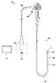
先ず、図1を参照して、本発明に係る固体撮像装置としての撮像ユニット1を具備する電子内視鏡(以下、単に内視鏡と記載する)101の構成の一例を説明する。 First, an example of the configuration of an electronic endoscope (hereinafter simply referred to as an endoscope) 101 including an imaging unit 1 as a solid-state imaging device according to the present invention will be described with reference to FIG.
本実施形態の内視鏡101は、人体などの被検体内に導入可能であって被検体内の所定の観察部位を光学的に撮像する構成を有している。 The
なお、内視鏡101が導入される被検体は、人体に限らず、他の生体であっても良いし、機械、建造物などの人工物であっても良い。 The subject into which the
内視鏡101は、被検体の内部に導入される挿入部102と、この挿入部102の基端に位置する操作部103と、この操作部103から延出するユニバーサルコード104とで主に構成されている。 The
挿入部102は、先端に配設される先端部110、この先端部110の基端側に配設される湾曲自在な湾曲部109およびこの湾曲部109の基端側に配設され操作部103の先端側に接続される可撓性を有する可撓管部108が連設されて構成されている。 The
なお、内視鏡101は、挿入部102に可撓性を有する部位を具備しない、所謂硬性鏡と称される形態のものであってもよい。 Note that the
詳しくは後述するが、先端部110には、撮像ユニット1が設けられている。また、操作部103には、湾曲部109の湾曲を操作するためのアングル操作ノブ106が設けられている。 As will be described in detail later, the imaging unit 1 is provided at the
ユニバーサルコード104の基端部には、外部装置120に接続される内視鏡コネクタ105が設けられている。内視鏡コネクタ105が接続される外部装置120は、モニタなどの画像表示部121にケーブルを介して接続されている。 An
また、内視鏡101は、ユニバーサルコード104、操作部103および挿入部102内に挿通された複合ケーブル115および外部装置120に設けられた光源部からの照明光を伝送するライトガイドである光ファイバ束(不図示)を有している。 The
複合ケーブル115は、内視鏡コネクタ105と撮像ユニット1とを電気的に接続するように構成されている。内視鏡コネクタ105が外部装置120に接続されることによって、撮像ユニット1は、複合ケーブル115を介して外部装置120に電気的に接続される。 The
この複合ケーブル115を介して、外部装置120から撮像ユニット1への電力の供給および外部装置120と撮像ユニット1との間の通信が行われる。 Via this
外部装置120には、画像処理部が設けられている。この画像処理部は、撮像ユニット1から出力された撮像素子出力信号に基づいて映像信号を生成し、画像表示部121に出力する。即ち、本実施形態では、撮像ユニット1により撮像された光学像(内視鏡像)が、映像として画像表示部121に表示される。 The
なお、内視鏡101は、外部装置120または画像表示部121に接続する構成に限定されず、例えば、画像処理部またはモニタの一部または全部を有する構成であっても良い。 Note that the
また、ライトガイドは、外部装置120の光源部から発せられた光を、先端部110の照明光出射部としての照明窓まで伝送するように構成されている。さらに、光源部は、内視鏡101の操作部103または先端部110に配設される構成であってもよい。 The light guide is configured to transmit the light emitted from the light source unit of the
次に、先端部110に設けられる撮像ユニット1の構成を説明する。なお、以下の説明においては、撮像ユニット1から被写体へ向かう方向(各図において左方)を先端、前方または物体側と称し、その反対の方向を基端、後方または像側と称する場合がある。 Next, the configuration of the imaging unit 1 provided at the
図2に示すように、挿入部102の先端部110は、その先端面111に観察窓21と、ここでは2つの照明窓22と、処置具チャンネル開口部23と、が配設されている。 As shown in FIG. 2, the
そして、先端部110には、図3に示すように、撮像ユニット1および管状部材24が挿通して保持固定される金属ブロック体である先端硬質部30が配設されている。 As shown in FIG. 3, the
管状部材24は、処置具チャンネル25の先端が接続され、この処置具チャンネル25の先端位置を位置決めする外向フランジ24aが形成されている。 The distal end of the
処置具チャンネル25は、挿入部102から操作部103の内部に配設され、基端が操作部103に設けられた処置具挿通口に接続されている。 The
先端硬質部30は、撮像ユニット1、管状部材24および処置具チャンネル25の先端部分を覆う外装管状部材26の先端が外嵌接続されている。そして、外装管状部材26の基端は、湾曲部109に設けられる最先端の湾曲駒(不図示)に嵌合接続されている。 The distal end of the outer
また、外装管状部材26は、糸巻接着部27によって、湾曲部109を被覆する湾曲ゴム28の先端が固定されている。 In addition, the outer
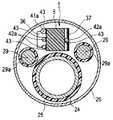
なお、先端部110内には、図4に示すように、撮像ユニット1の他、管状部材24に接続された処置具チャンネル25および複数、ここでは2つの上述したライトガイド29が配置されている。 As shown in FIG. 4, in addition to the imaging unit 1, the
複数のライトガイド29は、それぞれ外皮29aに被覆されており、先端端面が図2に示した照明窓22の背面に対向するように先端部分が先端硬質部30に挿通固定されている。 Each of the plurality of light guides 29 is covered with an
また、内視鏡101におけるその他の構成要素は、従来と同様であるため、それら構成要素の詳細な説明を省略する。 Further, since the other components in the
ここで、本実施の形態の固体撮像装置としての撮像ユニット1について、以下に詳しく説明する。
撮像ユニット1は、図5に示すように、前方となる物体側から順に、レンズホルダ2、撮像素子ホルダ3、撮像素子4および回路基板5を有して主に構成されている。Here, the imaging unit 1 as the solid-state imaging device of the present embodiment will be described in detail below.
As shown in FIG. 5, the imaging unit 1 mainly includes a lens holder 2, an
レンズホルダ2内には、ここでは対物光学系としての複数の対物レンズ群31が配設されている。最先端の対物レンズは、図2に示した観察窓21を構成している、撮像ユニット1のレンズホルダ2は、撮像素子ホルダ3と嵌合されている。撮像素子ホルダ3は、基端側の内部に接合レンズ33が設けられると共に、固体撮像素子4の図示しない受光部を保護するカバーガラス34と光軸調整をした上で接合されている。 In the lens holder 2, a plurality of
撮像素子4は、非常に小型な矩形状の電子部品である。この撮像素子4は、入射される撮影光に応じた電気信号を所定のタイミングで出力する複数の素子が面状の受光部に配列されたものであり、例えば一般にCCD(電荷結合素子)、CMOS(相補型金属酸化膜半導体)センサなどと称される形式、あるいはその他の各種の形式が適用されている。この撮像素子4は、基端側となる背面が回路基板5と接合されている。 The image sensor 4 is a very small rectangular electronic component. The imaging device 4 is a device in which a plurality of devices that output electrical signals corresponding to incident photographing light at a predetermined timing are arranged in a planar light-receiving unit, for example, generally a CCD (charge coupled device), CMOS A form called a (complementary metal oxide semiconductor) sensor or other various forms are applied. The imaging element 4 has a back surface that is the base end side bonded to the
ここでの回路基板5は、基材がガラスエポキシ樹脂またはセラミックの積層基板から構成された硬質基板として、例えば多層基板から構成されている。この回路基板5は、撮像素子4の背面に熱硬化接着剤などを介して面接合され、複数の電子部品35,36が実装され、内部に図示しない電子部品が埋設された板状ブロックの芯線接続部5aと、この芯線接続部5aの基端中央部分から段差を有して後方に突出するように延設された突出部となる外部導体接続部5bと、を有している。 The
この硬質基板としての回路基板5は、芯線接続部5aの下面にフレキシブルプリント基板(以下、FPCと記載する)37が電気的に接続されており、このFPC37の先端側から延設されたインナーリードが撮像素子4の下方前面に形成されたバンプと電気的に接続されている。これにより、撮像素子4に駆動電源が供給され、回路基板5との信号の授受が行われる。 The
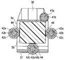
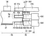
回路基板5の芯線接続部5aの後方の表裏面には、電源線41の芯線41aおよび複数の信号線42の芯線42aが半田によって接続される複数の導体ランド43が配設されている。 A plurality of conductor lands 43 to which the
また、回路基板5の外部導体接続部5bの表裏面には、少なくとも1つの導体ランド43と回路基板5の長手方向に沿った延長方向に、複数の信号線42における外皮42dが剥かれた状態の外部導体42cの外径部が接続される1つ乃至複数の外部導体ランド44が配設されている。 In addition, on the front and back surfaces of the external
即ち、回路基板5は、複合ケーブル115から延設された撮像信号、駆動信号などを授受する電源線41のおよび信号線42の芯線41a,42aが導体ランド43に半田によって電気的に接続されており、信号線42の外部導体42cの外径部が外部導体ランド44に半田によって電気的に接続されている。 In other words, the
なお、ここでの複数の信号線42は、同軸ケーブルが用いられている。これら複数の信号線42は、挿入部102内において、電源線41と共に複合ケーブル115内に配設されている。 The plurality of
複合ケーブル115は、図6に示すように、銅線などの総合シールド115aに外皮115bが被覆された構成となっている。また、電源線41は、芯線41aが絶縁樹脂から形成された外皮41bによって被覆された構成となっている。 As shown in FIG. 6, the
同軸線である複数の信号線42は、芯線42aがインピーダンスをコントロールする樹脂製の誘電体42b内に挿通しており、この誘電体42bの外周を覆う、例えば細い導体が編組されて、GNDとして利用される上述の外部導体42cが絶縁樹脂から形成された外皮42dに被覆された構成となっている。 A plurality of
これら電源線41および複数の信号線42は、撮像ユニット1と電気的に接続される際に、複合ケーブル115の先端から延出し、それぞれの外皮41b,42dが剥ぎ取られる。 When the
電源線41は、図7に示すように、芯線41aが撮像ユニット1の回路基板5における芯線接続部5aの表面、ここでは紙面に向かって見た上面側の導体ランド43の少なくとも1つに半田によって電気的に接続される。このとき、電源線41は、図8に示すように、外皮41bが外部導体接続部5bと重畳するように芯線41aが剥き出されて導体ランド43に接続される。 As shown in FIG. 7, the
また、複数の信号線42も電源線41と同様に、ぞれぞれの芯線42aが撮像ユニット1の回路基板5における芯線接続部5aの表裏面、ここでは紙面に向かって見た上下面の所定の導体ランド43に半田によって電気的に接続される(図7参照)。 Similarly to the
このとき、複数の信号線42は、図5に示したように、誘電体42bの先端位置が芯線接続部5aに重ならないように芯線接続部5aの基端に近接した位置となるように剥ぎ取られて芯線42aが剥き出された状態となっている。これにより信号線42は積層基板5aに対して平行に接続できるため、信号線42が紙面の上下方向に曲がって撮像ユニットの外形が大きくなることを防ぐことができる。 At this time, as shown in FIG. 5, the plurality of
そして、外部導体42cは、芯線42aと短絡しないように誘電体42bの先端よりも若干後方側に先端が位置するように切り取られて、誘電体42bを覆った状態で外部導体接続部5bの表裏面に設けられた所定の外部導体ランド44に外径部としての外周部が半田によって電気的に接続される(図8参照)。 The
なお、各信号線用に設けられた複数の外部導体ランド44は、同じGND用のため一括にまとめ、本実施例では外部導体接続部5bの上下面に各々広いケーブルランドを配置しても良い。 The plurality of external conductor lands 44 provided for each signal line are collectively used for the same GND, and wide cable lands may be arranged on the upper and lower surfaces of the external
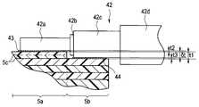
回路基板5は、図9に示すように、芯線接続部5aおよび外部導体接続部5bを積層する基材によって一体形成し、芯線接続部5aとなる部分の表裏面に単数または複数、ここでは2枚のシート5cをさらに積層して外部導体接続部5bの段差が形成されている。 As shown in FIG. 9, the
具体的には、先ず、信号線42の芯線42aの外径部と外部導体の外径部の寸法差δt、即ち、信号線42の誘電体の厚さと外部導体の厚さの和がシート5cの略整数倍の厚さとなっている。なお、回路基板5は、ここでは、上記寸法差δtがシート5cの厚さの約2倍となっており、2枚のシート5cを積層して、芯線接続部5aに対して内径方向に所定の高さ寸法t1を有した外部導体接続部5bの段差が形成される。 Specifically, first, the dimensional difference δt between the outer diameter portion of the
したがって、回路基板5に形成される外部導体接続部5bの段差の高さ寸法t1は、芯線42aの外径部と外部導体の外径部の寸法差δtと略同じ(t1=δt)となっている。 Therefore, the height dimension t1 of the step of the outer
なお、芯線接続部5aの導体ランド43の厚さ寸法t2と外部導体接続部5bの外部導体ランド44の厚さ寸法t3も、同じ金属箔となっているため同じ(t2=t3)となっている。 The thickness dimension t2 of the
このように、信号線42が接続される回路基板5は、信号線42の芯線42aの外径部と外部導体の外径部の寸法差δtに応じて、シート5cを単数または複数組み合わせて芯線接続部5aに対して中心方向に所定の高さ寸法t1を有した外部導体接続部5bの段差を形成される。 As described above, the
以上に説明したように撮像ユニット1は、回路基板5に電源線41および複数の信号線42の芯線41a,42aが接続される芯線接続部5aと、この芯線接続部5aに対して外形中心方向に段差を有して、複数の信号線42の外部導体42cが接続される外部導体接続部5bと、を備えた構成となっている。 As described above, the imaging unit 1 includes the core
そして、撮像ユニット1は、回路基板5において、1つの信号線42が接続される芯線接続部5aの導体ランド43と外部導体接続部5bの外部導体ランド44が回路基板5の長手方向に沿った方向に配置されている。 Then, in the imaging unit 1, in the
これにより、撮像ユニット1は、複数の信号線42を長手方向に沿って直線的に回路基板5に接続することができる。即ち、複数の信号線42は、芯線42aを芯線接続部5aの導体ランド43に接続された状態から略直線状態で外部導体42cを外部導体接続部5bの外部導体ランド44と接続することができる。 Thereby, the imaging unit 1 can connect the plurality of
以上のように構成された撮像ユニット1は、従来のようにグランド用ジャンパ線などに複数の信号線42の外部導体42cを絡げることをしなくてよく、GND用の外部導体ランド44に外皮42dを剥いただけの状態で電気的に接続でき、回路基板5を短縮化することができると共に、外部導体42cの結束部がなく外径方向に膨らむことがないため細径化することができる。 The imaging unit 1 configured as described above does not need to entangle the
即ち、硬質基板である回路基板5から基端側に延出した外部導体接続部5bは、各信号線42を積層基板5aの所定の位置に引き回すためのスペースを利用しており、デットスペースの有効利用によって、回路基板5の硬質長が延びることなく短縮化することができる。 That is, the outer
以上により、本実施の形態の撮像ユニット1は、内視鏡101の挿入部102の先端部110に内蔵される構成において、小型化することができるため、先端部110も小型となり、挿入部102の細径化にも寄与する構成とすることができる。 As described above, since the imaging unit 1 according to the present embodiment can be reduced in size in the configuration built in the
さらに、撮像ユニット1は、回路基板5に段差を設けることで、電源線41および複数の信号線42の芯線41a,42aを導体ランド43に半田付けするときの半田材が表面張力によって、外部導体接続部5b側に流れ難く、複数の信号線42の外部導体42cとの短絡も防止することができ、従来のように挿入部長手方向にスペースをとる必要がないので硬質長を短縮するという利点もある。 Further, the imaging unit 1 is provided with a step on the
(変形例)
撮像ユニット1は、以下に説明する種々の変形例の構成としてもよい。なお、以下に説明する各種変形例において、それぞれの構成を組み合わせることもできることは勿論である。(Modification)
The imaging unit 1 may have various modified configurations described below. Of course, the various configurations described below can also be combined with each other.
(第1の変形例)
図10は、第1の変形例の撮像ユニットの回路基板の外部導体接続部の構成を示す断面図である。(First modification)
FIG. 10 is a cross-sectional view showing the configuration of the external conductor connecting portion of the circuit board of the imaging unit of the first modification.
図10に示すように、撮像ユニット1は、回路基板5の外部導体接続部5bに複数の信号線42の外部導体42cが接続される外部導体ランド44を設ける部分に外部導体42cの形状に合わせた断面円弧状の凹部5dを形成してもよい。 As shown in FIG. 10, the imaging unit 1 matches the shape of the
このように撮像ユニット1は、回路基板5の外部導体接続部5bに凹部5dを形成して、凹部5d表面に外部導体ランド44を設けることで、信号線42を接続する位置決めが容易となり、外部導体42cの外部導体ランド44への半田付けが容易となり組立性が良くなる。 As described above, the imaging unit 1 has the
なお、ここでの回路基板5は、外部導体接続部5bに電源線41が係合する断面円弧状の凹部5eも形成されている。そのため、電源線41の回路基板5への位置決めも容易となる。 In addition, the
さらに、凹部5dの深さ寸法を外部導体ランド44、信号線42の誘電体42bおよび外部導体42cのそれぞれの厚さ寸法の合計(和)とすることで、芯線接続部5aに対して外部導体接続部5bの段差を設けなくてもよくなる。 Furthermore, the depth dimension of the
(第2の変形例)
図11は、第2の変形例の電源線および複数の信号線が接続された回路基板の構成を示す側面図、図12は図11のXII−XII線に沿った撮像ユニットの構成を示す断面図である。(Second modification)
11 is a side view showing the configuration of the circuit board to which the power supply line and the plurality of signal lines of the second modified example are connected, and FIG. 12 is a cross-sectional view showing the configuration of the imaging unit along the line XII-XII in FIG. FIG.
図11および図12に示すように、撮像ユニット1は、複数の信号線42が回路基板5の外部導体接続部5bの両側面に接続する構成としてもよい。 As shown in FIGS. 11 and 12, the imaging unit 1 may have a configuration in which a plurality of
具体的には、撮像ユニット1は、回路基板5の芯線接続部5aまたは外部導体接続部5bの両側面に、信号線42の芯線42aまたは外部導体42cが接続される導体ランド43または外部導体ランド44が形成されている。 Specifically, the imaging unit 1 includes the
そして、ここでの外部導体接続部5bは、芯線接続部5aに対して側面方向にも段差を有した構成となっており、回路基板5の両側面に接続される信号線42を長手方向に沿って直線的に接続することができるようになっている。 The outer
このような構成とした撮像ユニット1は、上述の効果に加え、回路基板5の設計の自由度を向上させることができる。 The imaging unit 1 having such a configuration can improve the degree of freedom in designing the
(第3の変形例)
図13は、第3の変形例の電源線および複数の信号線が接続された回路基板の構成を示す側面図、図14は図13のXIV−XIV線に沿った撮像ユニットの構成を示す断面図、図15は芯線接続部に外部導体接続部が接合される前の状態を示す側面図である。(Third Modification)
13 is a side view showing the configuration of the circuit board to which the power supply line and the plurality of signal lines of the third modification are connected, and FIG. 14 is a cross-sectional view showing the configuration of the imaging unit along the XIV-XIV line in FIG. FIG. 15 and FIG. 15 are side views showing a state before the outer conductor connecting portion is joined to the core wire connecting portion.
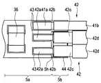
ここでの撮像ユニット1は、図13から図15に示すように、第2の変形例と同様に、複数の信号線42が回路基板5の外部導体接続部5bの両側面に接続する構成となっており、回路基板5の芯線接続部5aに対して外部導体接続部5bが装着自在な別体構成となっている。 As shown in FIGS. 13 to 15, the imaging unit 1 here has a configuration in which a plurality of
具体的には、回路基板5は、芯線接続部5aが基端面の中央部分から内部に向けて矩形状の凹部5fが形成されており、外部導体接続部5bが先端面の中央部分から芯線接続部5aの凹部5fと相似の矩形状の凸部5gが形成されている。 Specifically, the
このように、回路基板5は、外部導体接続部5bの凸部5gが芯線接続部5aの凹部5fと係合されることで、外部導体接続部5bが芯線接続部5aに装着される。なお、外部導体接続部5bと芯線接続部5aは、接着剤などによって固着される。 As described above, in the
また、芯線接続部5aは、基端面の下部側の両側部分に2つの電気接点45が設けられている。そして、外部導体接続部5bは、先端面の基端面の下部側の両側部分に芯線接続部5aの2つの電気接点45に接触して電気的に接続される2つの電気接点46が設けられている。 Further, the core
そして、これら接触した電気接点45,46は、フィレット状の半田などによって電気的な接続が確保される。 The
なお、これら電気接点45,46は、GND用の導体と電気的に接続され、外部導体接続部5bにおいては外部導体ランド44と内部配線を介して電気的に接続されている。 The
このような構成とすることで、撮像ユニット1は、上述の効果に加え、回路基板5において、外部導体接続部5bに予め複数の信号線42が接続されたユニットを組立てた後に、芯線接続部5aに外部導体接続部5bを装着固定することができ、組立性を向上させることができる。 By adopting such a configuration, in addition to the above-described effects, the imaging unit 1 assembles a unit in which a plurality of
さらに、回路基板5は、芯線接続部5aと外部導体接続部5bを別体とすることで、一体の構成に比して、ブロック状の積層体からダイシングなどによって小さな外部導体接続部5bを形成する必要が無くなり、製作が容易となる。 Further, the
(第4の変形例)
図16は、第4の変形例の複数の信号線が接続された回路基板の構成を示す側面図、図17は図16のXVII−XVII線に沿った撮像ユニットの構成を示す断面図、図18は図16のXVIII−XVIII線に沿った撮像ユニットの構成を示す断面図、図19は金属製の外部導体接続部の構成を示す斜視図である。(Fourth modification)
16 is a side view showing a configuration of a circuit board to which a plurality of signal lines according to a fourth modification are connected, and FIG. 17 is a cross-sectional view showing a configuration of an imaging unit along the line XVII-XVII in FIG. 18 is a cross-sectional view showing the configuration of the imaging unit along the line XVIII-XVIII in FIG. 16, and FIG. 19 is a perspective view showing the configuration of the metal outer conductor connecting portion.
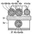
ここでの撮像ユニット1は、図16から図19に示すように、回路基板5の芯線接続部5aに対して金属などの導電体から形成された略板状の外部導体接続部51が装着自在な別体構成となっている。 In the imaging unit 1 here, as shown in FIGS. 16 to 19, a substantially plate-like external
具体的には、回路基板5は、芯線接続部5aの両側面に、ここでは片側2つの電気接点49が設けられており、図17に示すように、電気接点49に外部導体接続部51の2つの腕部51a(図19参照)が半田によって電気的に接続されている。 Specifically, the
これら芯線接続部5aに設けられた電気接点49は、内部配線によってGND用の導体と電気的に接続されている。 The
また、複数の信号線42は、図18に示すように、外部導体42cが外部導体接続部51の板状部51bの表裏面に直接、半田によって電気的に接続されている。 In addition, as shown in FIG. 18, in the plurality of
なお、外部導体接続部51は、図19に示すように、板状部51bの先端側の両側部から前方に2つの腕部51aが延設された構成となっている。 As shown in FIG. 19, the outer
このような構成とすることで、撮像ユニット1は、上述の効果に加え、第3の実施の形態と同様に、回路基板5において、外部導体接続部51に予め複数の信号線42が接続されたユニットを組立てた後に、芯線接続部5aに外部導体接続部5bを装着固定することができ、組立性を向上させることができる。 With such a configuration, in addition to the above-described effects, the imaging unit 1 has a plurality of
なお、芯線接続部5aの所望の位置に外部導体接続部51を装着固定すると、上述の図9を用いて説明したように、芯線42aが接続される芯線接続部5aの面と外部導体42cが接続される外部導体接続部5bの面が決められた高さになっている。 If the outer
さらに、撮像ユニット1は、回路基板5の外部導体接続部51自体が導電体であるため、信号線42の外部導体42cを電気的に接続するための外部導体ランドを設ける必要がなく、容易に芯線接続部5aとの電気的接続が行える。 Furthermore, since the external
(第5の変形例)
図20は、第5の変形例の複数の信号線が接続された回路基板の構成を示す上面図、図21は複数の信号線が接続された回路基板の構成を示す側面図、図22は図21のXXII−XXII線に沿った撮像ユニットの構成を示す断面図である。(Fifth modification)
20 is a top view showing the configuration of a circuit board to which a plurality of signal lines of the fifth modification are connected, FIG. 21 is a side view showing the configuration of a circuit board to which a plurality of signal lines are connected, and FIG. It is sectional drawing which shows the structure of the imaging unit along the XXII-XXII line | wire of FIG.
ここでの撮像ユニット1は、図20から図21に示すように、回路基板5の外部導体接続部5bの表裏面に複数の信号線42の外部導体42cが接続される外部導体ランド44を設ける部分を切り欠き形成または溝形成された段差部5h,5iを有している。 As shown in FIGS. 20 to 21, the imaging unit 1 here has external conductor lands 44 to which the
なお、外部導体接続部5bの裏面に形成された段差部5iは、外部導体接続部5bの断面が凹部状となるように形成されている。 The
このように撮像ユニット1は、回路基板5の外部導体接続部5bの表裏面に段差部5h,5iを形成して、これら段差部5h,5iの各表面に外部導体ランド44を設けることで、第1の変形例と同様に、信号線42を接続する位置決めが容易となり、外部導体42cの外部導体ランド44への半田付けが容易となり組立性が良くなる。 As described above, the imaging unit 1 forms the
そして、ここでの撮像ユニット1は、第1の変形例のように半円状の凹部5dを形成する構成に比して、外部導体接続部5bの表裏面に段差部5h,5iを容易に形成することができるため加工性が良い構成となっている。 And the imaging unit 1 here has stepped
さらに、ここでも段差部5h,5iの深さ寸法を外部導体ランド44、信号線42の誘電体42bおよび外部導体42cのそれぞれの厚さ寸法の合計(和)とすることで、芯線接続部5aに対して外部導体接続部5bに段差を更に設けなくてもよくなる。 Furthermore, here, the depth dimension of the stepped
なお、上述した実施の形態および変形例の撮像ユニット1は、所謂縦置きタイプの撮像素子4を例示したが、例えば、プリズムなどの反射部材を用いて屈折させた撮影光を検出する、所謂横置きタイプの構成にも適用可能である。 In addition, although the imaging unit 1 of the embodiment and the modification described above exemplifies a so-called vertical-type imaging device 4, for example, so-called horizontal detection of photographic light refracted using a reflecting member such as a prism is used. It can also be applied to a stand-up type configuration.
また、上述の内視鏡101は、所謂軟性鏡を例示したが、勿論、外科手術などに用いられる硬性鏡、さらには医療用に限られることなく、工業用内視鏡などのあらゆる撮像ユニット1を備えた電子内視鏡に適用可能な技術である。 The
そして、以上の各実施の形態に記載した発明は、それら実施の形態および変形例に限ることなく、その他、実施段階ではその要旨を逸脱しない範囲で種々の変形を実施し得ることが可能である。さらに、上記各実施の形態には、種々の段階の発明が含まれており、開示される複数の構成要件における適宜な組合せにより種々の発明が抽出され得るものである。 The invention described in each of the above embodiments is not limited to those embodiments and modifications, and various modifications can be made without departing from the scope of the invention at the stage of implementation. . Furthermore, the above embodiments include inventions at various stages, and various inventions can be extracted by appropriately combining a plurality of disclosed constituent elements.
例えば、各実施の形態に示される全構成要件から幾つかの構成要件が削除されても、述べられている課題が解決でき、述べられている効果が得られる場合には、この構成要件が削除された構成が発明として抽出され得るものである。 For example, even if some constituent requirements are deleted from all the constituent requirements shown in each embodiment, the stated requirements can be deleted if the stated problem can be solved and the stated effect can be obtained. The structure thus constructed can be extracted as an invention.
本出願は、2014年10月20日に日本国に出願された特願2014−213605号を優先権主張の基礎として出願するものであり、上記の内容は、本願明細書、請求の範囲、および図面に引用されたものである。 This application is filed on the basis of the priority claim of Japanese Patent Application No. 2014-213605 filed in Japan on October 20, 2014, and the above content includes the present specification, claims, and It is cited in the drawing.
Claims (4)
Translated fromJapanese前記撮像素子に電気的に接続されたフレキシブルプリント基板と、
前記撮像素子の背面に接着されると共に、前記フレキシブルプリント基板に電気的に接続された硬質基板と、
複数の同軸線を内蔵する信号ケーブルと、
を有する固体撮像装置において、
前記硬質基板は、前記同軸線の芯線が接続される芯線接続部を有する第1の面と、
前記同軸線の外部導体が接続される外部導体接続部を有し、前記第1の面と略平行な第2の面と、
を備え、
前記第2の面は、前記第1の面に対して段差を有し、
前記段差の高さ寸法は、前記同軸線の前記芯線の外径部と前記外部導体の外径部の寸法差と略同一であり、
前記第1の面と前記第2の面は、前記硬質基板の少なくとも表面と裏面とに形成され、 前記複数の同軸線が前記硬質基板の前記第1および第2の面に対して略平行に接続されることを特徴とする固体撮像装置。Andan imaging element,
A flexible printed circuit board electrically connected to the imaging device;
A hard substratethat is adhered to the back surface of the imaging device and electrically connectedto theflexible printed circuit board;
A signal cable containing aplurality of coaxial wires;
In a solid-state imaging device having
The hard substrate has a first surface having a core wire connecting portion to which the core wire of the coaxial line is connected;
An outer conductor connecting portion to which an outer conductor of the coaxial line is connected; a second surface substantially parallel to the first surface;
With
The second surface has a step with respect to the first surface,
The height dimension of the step is substantially the same as the dimensional difference between the outer diameter part of the core wire of the coaxial line and the outer diameter part of the outer conductor,
The first surface and the second surface are formed on at least the front surface and the back surface of the hard substrate, and theplurality of coaxial lines are substantially parallel to the first and second surfaces of the hard substrate. A solid-state imaging device characterized by being connected.
前記固体撮像装置が先端部内に内蔵された挿入部と、
を具備し、
前記信号ケーブルが前記挿入部の長手方向に略平行に配置されていることを特徴とする電子内視鏡。A solid-state imaging device according to claim1 ;
An insertion part in which thesolid-state imagingdevice is built in the tip part;
Comprising
An electronic endoscope, wherein the signal cable is disposed substantially parallel to a longitudinal direction of the insertion portion.
Applications Claiming Priority (3)
| Application Number | Priority Date | Filing Date | Title |
|---|---|---|---|
| JP2014213605 | 2014-10-20 | ||
| JP2014213605 | 2014-10-20 | ||
| PCT/JP2015/073112WO2016063603A1 (en) | 2014-10-20 | 2015-08-18 | Solid-state imaging device and electronic endoscope provided with solid-state imaging device |
Publications (2)
| Publication Number | Publication Date |
|---|---|
| JP5945653B1true JP5945653B1 (en) | 2016-07-05 |
| JPWO2016063603A1 JPWO2016063603A1 (en) | 2017-04-27 |
Family
ID=55760651
Family Applications (1)
| Application Number | Title | Priority Date | Filing Date |
|---|---|---|---|
| JP2016506011AActiveJP5945653B1 (en) | 2014-10-20 | 2015-08-18 | Solid-state imaging device and electronic endoscope provided with the solid-state imaging device |
Country Status (5)
| Country | Link |
|---|---|
| US (1) | US20160367122A1 (en) |
| EP (1) | EP3103381A4 (en) |
| JP (1) | JP5945653B1 (en) |
| CN (1) | CN106061365A (en) |
| WO (1) | WO2016063603A1 (en) |
Cited By (1)
| Publication number | Priority date | Publication date | Assignee | Title |
|---|---|---|---|---|
| US10930696B2 (en) | 2016-10-27 | 2021-02-23 | Olympus Corporation | Image pickup unit, endoscope, and method for manufacturing image pickup unit |
Families Citing this family (426)
| Publication number | Priority date | Publication date | Assignee | Title |
|---|---|---|---|---|
| US20070084897A1 (en) | 2003-05-20 | 2007-04-19 | Shelton Frederick E Iv | Articulating surgical stapling instrument incorporating a two-piece e-beam firing mechanism |
| US9060770B2 (en) | 2003-05-20 | 2015-06-23 | Ethicon Endo-Surgery, Inc. | Robotically-driven surgical instrument with E-beam driver |
| US11890012B2 (en) | 2004-07-28 | 2024-02-06 | Cilag Gmbh International | Staple cartridge comprising cartridge body and attached support |
| US8215531B2 (en) | 2004-07-28 | 2012-07-10 | Ethicon Endo-Surgery, Inc. | Surgical stapling instrument having a medical substance dispenser |
| US9072535B2 (en) | 2011-05-27 | 2015-07-07 | Ethicon Endo-Surgery, Inc. | Surgical stapling instruments with rotatable staple deployment arrangements |
| US11998198B2 (en) | 2004-07-28 | 2024-06-04 | Cilag Gmbh International | Surgical stapling instrument incorporating a two-piece E-beam firing mechanism |
| US7934630B2 (en) | 2005-08-31 | 2011-05-03 | Ethicon Endo-Surgery, Inc. | Staple cartridges for forming staples having differing formed staple heights |
| US11484312B2 (en) | 2005-08-31 | 2022-11-01 | Cilag Gmbh International | Staple cartridge comprising a staple driver arrangement |
| US10159482B2 (en) | 2005-08-31 | 2018-12-25 | Ethicon Llc | Fastener cartridge assembly comprising a fixed anvil and different staple heights |
| US7669746B2 (en) | 2005-08-31 | 2010-03-02 | Ethicon Endo-Surgery, Inc. | Staple cartridges for forming staples having differing formed staple heights |
| US9237891B2 (en) | 2005-08-31 | 2016-01-19 | Ethicon Endo-Surgery, Inc. | Robotically-controlled surgical stapling devices that produce formed staples having different lengths |
| US11246590B2 (en) | 2005-08-31 | 2022-02-15 | Cilag Gmbh International | Staple cartridge including staple drivers having different unfired heights |
| US20070106317A1 (en) | 2005-11-09 | 2007-05-10 | Shelton Frederick E Iv | Hydraulically and electrically actuated articulation joints for surgical instruments |
| US20110024477A1 (en) | 2009-02-06 | 2011-02-03 | Hall Steven G | Driven Surgical Stapler Improvements |
| US7845537B2 (en) | 2006-01-31 | 2010-12-07 | Ethicon Endo-Surgery, Inc. | Surgical instrument having recording capabilities |
| US20120292367A1 (en) | 2006-01-31 | 2012-11-22 | Ethicon Endo-Surgery, Inc. | Robotically-controlled end effector |
| US11224427B2 (en) | 2006-01-31 | 2022-01-18 | Cilag Gmbh International | Surgical stapling system including a console and retraction assembly |
| US11278279B2 (en) | 2006-01-31 | 2022-03-22 | Cilag Gmbh International | Surgical instrument assembly |
| US8708213B2 (en) | 2006-01-31 | 2014-04-29 | Ethicon Endo-Surgery, Inc. | Surgical instrument having a feedback system |
| US8186555B2 (en) | 2006-01-31 | 2012-05-29 | Ethicon Endo-Surgery, Inc. | Motor-driven surgical cutting and fastening instrument with mechanical closure system |
| US7753904B2 (en) | 2006-01-31 | 2010-07-13 | Ethicon Endo-Surgery, Inc. | Endoscopic surgical instrument with a handle that can articulate with respect to the shaft |
| US11793518B2 (en) | 2006-01-31 | 2023-10-24 | Cilag Gmbh International | Powered surgical instruments with firing system lockout arrangements |
| US8820603B2 (en) | 2006-01-31 | 2014-09-02 | Ethicon Endo-Surgery, Inc. | Accessing data stored in a memory of a surgical instrument |
| US20110295295A1 (en) | 2006-01-31 | 2011-12-01 | Ethicon Endo-Surgery, Inc. | Robotically-controlled surgical instrument having recording capabilities |
| US8992422B2 (en) | 2006-03-23 | 2015-03-31 | Ethicon Endo-Surgery, Inc. | Robotically-controlled endoscopic accessory channel |
| US8322455B2 (en) | 2006-06-27 | 2012-12-04 | Ethicon Endo-Surgery, Inc. | Manually driven surgical cutting and fastening instrument |
| US7506791B2 (en) | 2006-09-29 | 2009-03-24 | Ethicon Endo-Surgery, Inc. | Surgical stapling instrument with mechanical mechanism for limiting maximum tissue compression |
| US10568652B2 (en) | 2006-09-29 | 2020-02-25 | Ethicon Llc | Surgical staples having attached drivers of different heights and stapling instruments for deploying the same |
| US11980366B2 (en) | 2006-10-03 | 2024-05-14 | Cilag Gmbh International | Surgical instrument |
| US8684253B2 (en) | 2007-01-10 | 2014-04-01 | Ethicon Endo-Surgery, Inc. | Surgical instrument with wireless communication between a control unit of a robotic system and remote sensor |
| US8632535B2 (en) | 2007-01-10 | 2014-01-21 | Ethicon Endo-Surgery, Inc. | Interlock and surgical instrument including same |
| US11291441B2 (en) | 2007-01-10 | 2022-04-05 | Cilag Gmbh International | Surgical instrument with wireless communication between control unit and remote sensor |
| US8652120B2 (en) | 2007-01-10 | 2014-02-18 | Ethicon Endo-Surgery, Inc. | Surgical instrument with wireless communication between control unit and sensor transponders |
| US11039836B2 (en) | 2007-01-11 | 2021-06-22 | Cilag Gmbh International | Staple cartridge for use with a surgical stapling instrument |
| US20080169333A1 (en) | 2007-01-11 | 2008-07-17 | Shelton Frederick E | Surgical stapler end effector with tapered distal end |
| US7673782B2 (en) | 2007-03-15 | 2010-03-09 | Ethicon Endo-Surgery, Inc. | Surgical stapling instrument having a releasable buttress material |
| US8893946B2 (en) | 2007-03-28 | 2014-11-25 | Ethicon Endo-Surgery, Inc. | Laparoscopic tissue thickness and clamp load measuring devices |
| US11564682B2 (en) | 2007-06-04 | 2023-01-31 | Cilag Gmbh International | Surgical stapler device |
| US8931682B2 (en) | 2007-06-04 | 2015-01-13 | Ethicon Endo-Surgery, Inc. | Robotically-controlled shaft based rotary drive systems for surgical instruments |
| US7753245B2 (en) | 2007-06-22 | 2010-07-13 | Ethicon Endo-Surgery, Inc. | Surgical stapling instruments |
| US11849941B2 (en) | 2007-06-29 | 2023-12-26 | Cilag Gmbh International | Staple cartridge having staple cavities extending at a transverse angle relative to a longitudinal cartridge axis |
| US8573465B2 (en) | 2008-02-14 | 2013-11-05 | Ethicon Endo-Surgery, Inc. | Robotically-controlled surgical end effector system with rotary actuated closure systems |
| US7866527B2 (en) | 2008-02-14 | 2011-01-11 | Ethicon Endo-Surgery, Inc. | Surgical stapling apparatus with interlockable firing system |
| US8636736B2 (en) | 2008-02-14 | 2014-01-28 | Ethicon Endo-Surgery, Inc. | Motorized surgical cutting and fastening instrument |
| JP5410110B2 (en) | 2008-02-14 | 2014-02-05 | エシコン・エンド−サージェリィ・インコーポレイテッド | Surgical cutting / fixing instrument with RF electrode |
| US8758391B2 (en) | 2008-02-14 | 2014-06-24 | Ethicon Endo-Surgery, Inc. | Interchangeable tools for surgical instruments |
| US9179912B2 (en) | 2008-02-14 | 2015-11-10 | Ethicon Endo-Surgery, Inc. | Robotically-controlled motorized surgical cutting and fastening instrument |
| US11986183B2 (en) | 2008-02-14 | 2024-05-21 | Cilag Gmbh International | Surgical cutting and fastening instrument comprising a plurality of sensors to measure an electrical parameter |
| US7819298B2 (en) | 2008-02-14 | 2010-10-26 | Ethicon Endo-Surgery, Inc. | Surgical stapling apparatus with control features operable with one hand |
| US9585657B2 (en) | 2008-02-15 | 2017-03-07 | Ethicon Endo-Surgery, Llc | Actuator for releasing a layer of material from a surgical end effector |
| US11272927B2 (en) | 2008-02-15 | 2022-03-15 | Cilag Gmbh International | Layer arrangements for surgical staple cartridges |
| US11648005B2 (en) | 2008-09-23 | 2023-05-16 | Cilag Gmbh International | Robotically-controlled motorized surgical instrument with an end effector |
| US9005230B2 (en) | 2008-09-23 | 2015-04-14 | Ethicon Endo-Surgery, Inc. | Motorized surgical instrument |
| US8210411B2 (en) | 2008-09-23 | 2012-07-03 | Ethicon Endo-Surgery, Inc. | Motor-driven surgical cutting instrument |
| US9386983B2 (en) | 2008-09-23 | 2016-07-12 | Ethicon Endo-Surgery, Llc | Robotically-controlled motorized surgical instrument |
| US8608045B2 (en) | 2008-10-10 | 2013-12-17 | Ethicon Endo-Sugery, Inc. | Powered surgical cutting and stapling apparatus with manually retractable firing system |
| US8517239B2 (en) | 2009-02-05 | 2013-08-27 | Ethicon Endo-Surgery, Inc. | Surgical stapling instrument comprising a magnetic element driver |
| RU2525225C2 (en) | 2009-02-06 | 2014-08-10 | Этикон Эндо-Серджери, Инк. | Improvement of drive surgical suturing instrument |
| US8444036B2 (en) | 2009-02-06 | 2013-05-21 | Ethicon Endo-Surgery, Inc. | Motor driven surgical fastener device with mechanisms for adjusting a tissue gap within the end effector |
| US8851354B2 (en) | 2009-12-24 | 2014-10-07 | Ethicon Endo-Surgery, Inc. | Surgical cutting instrument that analyzes tissue thickness |
| US8220688B2 (en) | 2009-12-24 | 2012-07-17 | Ethicon Endo-Surgery, Inc. | Motor-driven surgical cutting instrument with electric actuator directional control assembly |
| US8783543B2 (en) | 2010-07-30 | 2014-07-22 | Ethicon Endo-Surgery, Inc. | Tissue acquisition arrangements and methods for surgical stapling devices |
| US9016542B2 (en) | 2010-09-30 | 2015-04-28 | Ethicon Endo-Surgery, Inc. | Staple cartridge comprising compressible distortion resistant components |
| US11925354B2 (en) | 2010-09-30 | 2024-03-12 | Cilag Gmbh International | Staple cartridge comprising staples positioned within a compressible portion thereof |
| US9232941B2 (en) | 2010-09-30 | 2016-01-12 | Ethicon Endo-Surgery, Inc. | Tissue thickness compensator comprising a reservoir |
| US11812965B2 (en) | 2010-09-30 | 2023-11-14 | Cilag Gmbh International | Layer of material for a surgical end effector |
| US9351730B2 (en) | 2011-04-29 | 2016-05-31 | Ethicon Endo-Surgery, Llc | Tissue thickness compensator comprising channels |
| US9629814B2 (en) | 2010-09-30 | 2017-04-25 | Ethicon Endo-Surgery, Llc | Tissue thickness compensator configured to redistribute compressive forces |
| US9386988B2 (en) | 2010-09-30 | 2016-07-12 | Ethicon End-Surgery, LLC | Retainer assembly including a tissue thickness compensator |
| US12213666B2 (en) | 2010-09-30 | 2025-02-04 | Cilag Gmbh International | Tissue thickness compensator comprising layers |
| US10945731B2 (en) | 2010-09-30 | 2021-03-16 | Ethicon Llc | Tissue thickness compensator comprising controlled release and expansion |
| US9788834B2 (en) | 2010-09-30 | 2017-10-17 | Ethicon Llc | Layer comprising deployable attachment members |
| US11298125B2 (en) | 2010-09-30 | 2022-04-12 | Cilag Gmbh International | Tissue stapler having a thickness compensator |
| US9364233B2 (en) | 2010-09-30 | 2016-06-14 | Ethicon Endo-Surgery, Llc | Tissue thickness compensators for circular surgical staplers |
| US8695866B2 (en) | 2010-10-01 | 2014-04-15 | Ethicon Endo-Surgery, Inc. | Surgical instrument having a power control circuit |
| AU2012250197B2 (en) | 2011-04-29 | 2017-08-10 | Ethicon Endo-Surgery, Inc. | Staple cartridge comprising staples positioned within a compressible portion thereof |
| US11207064B2 (en) | 2011-05-27 | 2021-12-28 | Cilag Gmbh International | Automated end effector component reloading system for use with a robotic system |
| US9044230B2 (en) | 2012-02-13 | 2015-06-02 | Ethicon Endo-Surgery, Inc. | Surgical cutting and fastening instrument with apparatus for determining cartridge and firing motion status |
| BR112014024098B1 (en) | 2012-03-28 | 2021-05-25 | Ethicon Endo-Surgery, Inc. | staple cartridge |
| JP6224070B2 (en) | 2012-03-28 | 2017-11-01 | エシコン・エンド−サージェリィ・インコーポレイテッドEthicon Endo−Surgery,Inc. | Retainer assembly including tissue thickness compensator |
| MX358135B (en) | 2012-03-28 | 2018-08-06 | Ethicon Endo Surgery Inc | Tissue thickness compensator comprising a plurality of layers. |
| US9101358B2 (en) | 2012-06-15 | 2015-08-11 | Ethicon Endo-Surgery, Inc. | Articulatable surgical instrument comprising a firing drive |
| US9282974B2 (en) | 2012-06-28 | 2016-03-15 | Ethicon Endo-Surgery, Llc | Empty clip cartridge lockout |
| JP6290201B2 (en) | 2012-06-28 | 2018-03-07 | エシコン・エンド−サージェリィ・インコーポレイテッドEthicon Endo−Surgery,Inc. | Lockout for empty clip cartridge |
| BR112014032776B1 (en) | 2012-06-28 | 2021-09-08 | Ethicon Endo-Surgery, Inc | SURGICAL INSTRUMENT SYSTEM AND SURGICAL KIT FOR USE WITH A SURGICAL INSTRUMENT SYSTEM |
| US20140005718A1 (en) | 2012-06-28 | 2014-01-02 | Ethicon Endo-Surgery, Inc. | Multi-functional powered surgical device with external dissection features |
| US20140001231A1 (en) | 2012-06-28 | 2014-01-02 | Ethicon Endo-Surgery, Inc. | Firing system lockout arrangements for surgical instruments |
| US9408606B2 (en) | 2012-06-28 | 2016-08-09 | Ethicon Endo-Surgery, Llc | Robotically powered surgical device with manually-actuatable reversing system |
| US12383267B2 (en) | 2012-06-28 | 2025-08-12 | Cilag Gmbh International | Robotically powered surgical device with manually-actuatable reversing system |
| US11278284B2 (en) | 2012-06-28 | 2022-03-22 | Cilag Gmbh International | Rotary drive arrangements for surgical instruments |
| US9289256B2 (en) | 2012-06-28 | 2016-03-22 | Ethicon Endo-Surgery, Llc | Surgical end effectors having angled tissue-contacting surfaces |
| RU2672520C2 (en) | 2013-03-01 | 2018-11-15 | Этикон Эндо-Серджери, Инк. | Hingedly turnable surgical instruments with conducting ways for signal transfer |
| BR112015021082B1 (en) | 2013-03-01 | 2022-05-10 | Ethicon Endo-Surgery, Inc | surgical instrument |
| US9629629B2 (en) | 2013-03-14 | 2017-04-25 | Ethicon Endo-Surgey, LLC | Control systems for surgical instruments |
| US9808244B2 (en) | 2013-03-14 | 2017-11-07 | Ethicon Llc | Sensor arrangements for absolute positioning system for surgical instruments |
| US9826976B2 (en) | 2013-04-16 | 2017-11-28 | Ethicon Llc | Motor driven surgical instruments with lockable dual drive shafts |
| BR112015026109B1 (en) | 2013-04-16 | 2022-02-22 | Ethicon Endo-Surgery, Inc | surgical instrument |
| US9775609B2 (en) | 2013-08-23 | 2017-10-03 | Ethicon Llc | Tamper proof circuit for surgical instrument battery pack |
| MX369362B (en) | 2013-08-23 | 2019-11-06 | Ethicon Endo Surgery Llc | Firing member retraction devices for powered surgical instruments. |
| US9962161B2 (en) | 2014-02-12 | 2018-05-08 | Ethicon Llc | Deliverable surgical instrument |
| JP6462004B2 (en) | 2014-02-24 | 2019-01-30 | エシコン エルエルシー | Fastening system with launcher lockout |
| BR112016021943B1 (en) | 2014-03-26 | 2022-06-14 | Ethicon Endo-Surgery, Llc | SURGICAL INSTRUMENT FOR USE BY AN OPERATOR IN A SURGICAL PROCEDURE |
| US10013049B2 (en) | 2014-03-26 | 2018-07-03 | Ethicon Llc | Power management through sleep options of segmented circuit and wake up control |
| US12232723B2 (en) | 2014-03-26 | 2025-02-25 | Cilag Gmbh International | Systems and methods for controlling a segmented circuit |
| US10004497B2 (en) | 2014-03-26 | 2018-06-26 | Ethicon Llc | Interface systems for use with surgical instruments |
| US20150272580A1 (en) | 2014-03-26 | 2015-10-01 | Ethicon Endo-Surgery, Inc. | Verification of number of battery exchanges/procedure count |
| BR112016023825B1 (en) | 2014-04-16 | 2022-08-02 | Ethicon Endo-Surgery, Llc | STAPLE CARTRIDGE FOR USE WITH A SURGICAL STAPLER AND STAPLE CARTRIDGE FOR USE WITH A SURGICAL INSTRUMENT |
| CN106456176B (en) | 2014-04-16 | 2019-06-28 | 伊西康内外科有限责任公司 | Fastener Cartridge Including Extensions With Different Configurations |
| US10470768B2 (en) | 2014-04-16 | 2019-11-12 | Ethicon Llc | Fastener cartridge including a layer attached thereto |
| US10327764B2 (en) | 2014-09-26 | 2019-06-25 | Ethicon Llc | Method for creating a flexible staple line |
| CN106456159B (en) | 2014-04-16 | 2019-03-08 | 伊西康内外科有限责任公司 | Fastener Cartridge Assembly and Nail Retainer Cover Arrangement |
| US20150297225A1 (en) | 2014-04-16 | 2015-10-22 | Ethicon Endo-Surgery, Inc. | Fastener cartridges including extensions having different configurations |
| US10135242B2 (en) | 2014-09-05 | 2018-11-20 | Ethicon Llc | Smart cartridge wake up operation and data retention |
| BR112017004361B1 (en) | 2014-09-05 | 2023-04-11 | Ethicon Llc | ELECTRONIC SYSTEM FOR A SURGICAL INSTRUMENT |
| US11311294B2 (en) | 2014-09-05 | 2022-04-26 | Cilag Gmbh International | Powered medical device including measurement of closure state of jaws |
| US10105142B2 (en) | 2014-09-18 | 2018-10-23 | Ethicon Llc | Surgical stapler with plurality of cutting elements |
| US11523821B2 (en) | 2014-09-26 | 2022-12-13 | Cilag Gmbh International | Method for creating a flexible staple line |
| CN107427300B (en) | 2014-09-26 | 2020-12-04 | 伊西康有限责任公司 | Surgical suture buttresses and auxiliary materials |
| US10076325B2 (en) | 2014-10-13 | 2018-09-18 | Ethicon Llc | Surgical stapling apparatus comprising a tissue stop |
| US9924944B2 (en) | 2014-10-16 | 2018-03-27 | Ethicon Llc | Staple cartridge comprising an adjunct material |
| US11141153B2 (en) | 2014-10-29 | 2021-10-12 | Cilag Gmbh International | Staple cartridges comprising driver arrangements |
| US10517594B2 (en) | 2014-10-29 | 2019-12-31 | Ethicon Llc | Cartridge assemblies for surgical staplers |
| US9844376B2 (en) | 2014-11-06 | 2017-12-19 | Ethicon Llc | Staple cartridge comprising a releasable adjunct material |
| US10736636B2 (en) | 2014-12-10 | 2020-08-11 | Ethicon Llc | Articulatable surgical instrument system |
| US10085748B2 (en) | 2014-12-18 | 2018-10-02 | Ethicon Llc | Locking arrangements for detachable shaft assemblies with articulatable surgical end effectors |
| MX389118B (en) | 2014-12-18 | 2025-03-20 | Ethicon Llc | SURGICAL INSTRUMENT WITH AN ANVIL THAT CAN BE SELECTIVELY MOVED ON A DISCRETE, NON-MOBILE AXIS RELATIVE TO A STAPLE CARTRIDGE. |
| US9943309B2 (en) | 2014-12-18 | 2018-04-17 | Ethicon Llc | Surgical instruments with articulatable end effectors and movable firing beam support arrangements |
| US9987000B2 (en) | 2014-12-18 | 2018-06-05 | Ethicon Llc | Surgical instrument assembly comprising a flexible articulation system |
| US10188385B2 (en) | 2014-12-18 | 2019-01-29 | Ethicon Llc | Surgical instrument system comprising lockable systems |
| US9844375B2 (en) | 2014-12-18 | 2017-12-19 | Ethicon Llc | Drive arrangements for articulatable surgical instruments |
| US9844374B2 (en) | 2014-12-18 | 2017-12-19 | Ethicon Llc | Surgical instrument systems comprising an articulatable end effector and means for adjusting the firing stroke of a firing member |
| US11154301B2 (en) | 2015-02-27 | 2021-10-26 | Cilag Gmbh International | Modular stapling assembly |
| US10180463B2 (en) | 2015-02-27 | 2019-01-15 | Ethicon Llc | Surgical apparatus configured to assess whether a performance parameter of the surgical apparatus is within an acceptable performance band |
| US10159483B2 (en) | 2015-02-27 | 2018-12-25 | Ethicon Llc | Surgical apparatus configured to track an end-of-life parameter |
| US10548504B2 (en) | 2015-03-06 | 2020-02-04 | Ethicon Llc | Overlaid multi sensor radio frequency (RF) electrode system to measure tissue compression |
| JP2020121162A (en) | 2015-03-06 | 2020-08-13 | エシコン エルエルシーEthicon LLC | Time dependent evaluation of sensor data to determine stability element, creep element and viscoelastic element of measurement |
| US9808246B2 (en) | 2015-03-06 | 2017-11-07 | Ethicon Endo-Surgery, Llc | Method of operating a powered surgical instrument |
| US10245033B2 (en) | 2015-03-06 | 2019-04-02 | Ethicon Llc | Surgical instrument comprising a lockable battery housing |
| US9924961B2 (en) | 2015-03-06 | 2018-03-27 | Ethicon Endo-Surgery, Llc | Interactive feedback system for powered surgical instruments |
| US10687806B2 (en) | 2015-03-06 | 2020-06-23 | Ethicon Llc | Adaptive tissue compression techniques to adjust closure rates for multiple tissue types |
| US9901342B2 (en) | 2015-03-06 | 2018-02-27 | Ethicon Endo-Surgery, Llc | Signal and power communication system positioned on a rotatable shaft |
| US9993248B2 (en) | 2015-03-06 | 2018-06-12 | Ethicon Endo-Surgery, Llc | Smart sensors with local signal processing |
| US10617412B2 (en) | 2015-03-06 | 2020-04-14 | Ethicon Llc | System for detecting the mis-insertion of a staple cartridge into a surgical stapler |
| US10441279B2 (en) | 2015-03-06 | 2019-10-15 | Ethicon Llc | Multiple level thresholds to modify operation of powered surgical instruments |
| US10433844B2 (en) | 2015-03-31 | 2019-10-08 | Ethicon Llc | Surgical instrument with selectively disengageable threaded drive systems |
| US10835249B2 (en) | 2015-08-17 | 2020-11-17 | Ethicon Llc | Implantable layers for a surgical instrument |
| US10105139B2 (en) | 2015-09-23 | 2018-10-23 | Ethicon Llc | Surgical stapler having downstream current-based motor control |
| US10363036B2 (en) | 2015-09-23 | 2019-07-30 | Ethicon Llc | Surgical stapler having force-based motor control |
| US10238386B2 (en) | 2015-09-23 | 2019-03-26 | Ethicon Llc | Surgical stapler having motor control based on an electrical parameter related to a motor current |
| US10327769B2 (en) | 2015-09-23 | 2019-06-25 | Ethicon Llc | Surgical stapler having motor control based on a drive system component |
| US10299878B2 (en) | 2015-09-25 | 2019-05-28 | Ethicon Llc | Implantable adjunct systems for determining adjunct skew |
| US10433846B2 (en) | 2015-09-30 | 2019-10-08 | Ethicon Llc | Compressible adjunct with crossing spacer fibers |
| US10478188B2 (en) | 2015-09-30 | 2019-11-19 | Ethicon Llc | Implantable layer comprising a constricted configuration |
| US10980539B2 (en) | 2015-09-30 | 2021-04-20 | Ethicon Llc | Implantable adjunct comprising bonded layers |
| US11890015B2 (en) | 2015-09-30 | 2024-02-06 | Cilag Gmbh International | Compressible adjunct with crossing spacer fibers |
| US10292704B2 (en) | 2015-12-30 | 2019-05-21 | Ethicon Llc | Mechanisms for compensating for battery pack failure in powered surgical instruments |
| US10368865B2 (en) | 2015-12-30 | 2019-08-06 | Ethicon Llc | Mechanisms for compensating for drivetrain failure in powered surgical instruments |
| US10265068B2 (en) | 2015-12-30 | 2019-04-23 | Ethicon Llc | Surgical instruments with separable motors and motor control circuits |
| BR112018016098B1 (en) | 2016-02-09 | 2023-02-23 | Ethicon Llc | SURGICAL INSTRUMENT |
| US11213293B2 (en) | 2016-02-09 | 2022-01-04 | Cilag Gmbh International | Articulatable surgical instruments with single articulation link arrangements |
| US10413291B2 (en) | 2016-02-09 | 2019-09-17 | Ethicon Llc | Surgical instrument articulation mechanism with slotted secondary constraint |
| US10448948B2 (en) | 2016-02-12 | 2019-10-22 | Ethicon Llc | Mechanisms for compensating for drivetrain failure in powered surgical instruments |
| US11224426B2 (en) | 2016-02-12 | 2022-01-18 | Cilag Gmbh International | Mechanisms for compensating for drivetrain failure in powered surgical instruments |
| US10258331B2 (en) | 2016-02-12 | 2019-04-16 | Ethicon Llc | Mechanisms for compensating for drivetrain failure in powered surgical instruments |
| US10413297B2 (en) | 2016-04-01 | 2019-09-17 | Ethicon Llc | Surgical stapling system configured to apply annular rows of staples having different heights |
| US10617413B2 (en) | 2016-04-01 | 2020-04-14 | Ethicon Llc | Closure system arrangements for surgical cutting and stapling devices with separate and distinct firing shafts |
| US10828028B2 (en) | 2016-04-15 | 2020-11-10 | Ethicon Llc | Surgical instrument with multiple program responses during a firing motion |
| US10426467B2 (en) | 2016-04-15 | 2019-10-01 | Ethicon Llc | Surgical instrument with detection sensors |
| US10456137B2 (en) | 2016-04-15 | 2019-10-29 | Ethicon Llc | Staple formation detection mechanisms |
| US10405859B2 (en) | 2016-04-15 | 2019-09-10 | Ethicon Llc | Surgical instrument with adjustable stop/start control during a firing motion |
| US10335145B2 (en) | 2016-04-15 | 2019-07-02 | Ethicon Llc | Modular surgical instrument with configurable operating mode |
| US11179150B2 (en) | 2016-04-15 | 2021-11-23 | Cilag Gmbh International | Systems and methods for controlling a surgical stapling and cutting instrument |
| US11607239B2 (en) | 2016-04-15 | 2023-03-21 | Cilag Gmbh International | Systems and methods for controlling a surgical stapling and cutting instrument |
| US10492783B2 (en) | 2016-04-15 | 2019-12-03 | Ethicon, Llc | Surgical instrument with improved stop/start control during a firing motion |
| US10357247B2 (en) | 2016-04-15 | 2019-07-23 | Ethicon Llc | Surgical instrument with multiple program responses during a firing motion |
| US10363037B2 (en) | 2016-04-18 | 2019-07-30 | Ethicon Llc | Surgical instrument system comprising a magnetic lockout |
| US11317917B2 (en) | 2016-04-18 | 2022-05-03 | Cilag Gmbh International | Surgical stapling system comprising a lockable firing assembly |
| US20170296173A1 (en) | 2016-04-18 | 2017-10-19 | Ethicon Endo-Surgery, Llc | Method for operating a surgical instrument |
| WO2018003510A1 (en)* | 2016-06-29 | 2018-01-04 | オリンパス株式会社 | Imaging unit and endoscope |
| US10500000B2 (en) | 2016-08-16 | 2019-12-10 | Ethicon Llc | Surgical tool with manual control of end effector jaws |
| CN109963493A (en)* | 2016-10-27 | 2019-07-02 | 奥林巴斯株式会社 | Endoscope |
| US20180168615A1 (en) | 2016-12-21 | 2018-06-21 | Ethicon Endo-Surgery, Llc | Method of deforming staples from two different types of staple cartridges with the same surgical stapling instrument |
| US10813638B2 (en) | 2016-12-21 | 2020-10-27 | Ethicon Llc | Surgical end effectors with expandable tissue stop arrangements |
| US10542982B2 (en) | 2016-12-21 | 2020-01-28 | Ethicon Llc | Shaft assembly comprising first and second articulation lockouts |
| US10758229B2 (en) | 2016-12-21 | 2020-09-01 | Ethicon Llc | Surgical instrument comprising improved jaw control |
| JP7010956B2 (en) | 2016-12-21 | 2022-01-26 | エシコン エルエルシー | How to staple tissue |
| US11090048B2 (en) | 2016-12-21 | 2021-08-17 | Cilag Gmbh International | Method for resetting a fuse of a surgical instrument shaft |
| US10426471B2 (en) | 2016-12-21 | 2019-10-01 | Ethicon Llc | Surgical instrument with multiple failure response modes |
| US10973516B2 (en) | 2016-12-21 | 2021-04-13 | Ethicon Llc | Surgical end effectors and adaptable firing members therefor |
| US10582928B2 (en) | 2016-12-21 | 2020-03-10 | Ethicon Llc | Articulation lock arrangements for locking an end effector in an articulated position in response to actuation of a jaw closure system |
| JP6983893B2 (en) | 2016-12-21 | 2021-12-17 | エシコン エルエルシーEthicon LLC | Lockout configuration for surgical end effectors and replaceable tool assemblies |
| CN110087565A (en) | 2016-12-21 | 2019-08-02 | 爱惜康有限责任公司 | Surgical stapling system |
| US11419606B2 (en) | 2016-12-21 | 2022-08-23 | Cilag Gmbh International | Shaft assembly comprising a clutch configured to adapt the output of a rotary firing member to two different systems |
| MX2019007295A (en) | 2016-12-21 | 2019-10-15 | Ethicon Llc | Surgical instrument system comprising an end effector lockout and a firing assembly lockout. |
| US10898186B2 (en) | 2016-12-21 | 2021-01-26 | Ethicon Llc | Staple forming pocket arrangements comprising primary sidewalls and pocket sidewalls |
| US10485543B2 (en) | 2016-12-21 | 2019-11-26 | Ethicon Llc | Anvil having a knife slot width |
| US10568625B2 (en) | 2016-12-21 | 2020-02-25 | Ethicon Llc | Staple cartridges and arrangements of staples and staple cavities therein |
| JP7010957B2 (en) | 2016-12-21 | 2022-01-26 | エシコン エルエルシー | Shaft assembly with lockout |
| US11134942B2 (en) | 2016-12-21 | 2021-10-05 | Cilag Gmbh International | Surgical stapling instruments and staple-forming anvils |
| JP2020501815A (en) | 2016-12-21 | 2020-01-23 | エシコン エルエルシーEthicon LLC | Surgical stapling system |
| US10695055B2 (en) | 2016-12-21 | 2020-06-30 | Ethicon Llc | Firing assembly comprising a lockout |
| US10980536B2 (en) | 2016-12-21 | 2021-04-20 | Ethicon Llc | No-cartridge and spent cartridge lockout arrangements for surgical staplers |
| US20180168625A1 (en) | 2016-12-21 | 2018-06-21 | Ethicon Endo-Surgery, Llc | Surgical stapling instruments with smart staple cartridges |
| WO2018158897A1 (en)* | 2017-03-01 | 2018-09-07 | オリンパス株式会社 | Cable mounting structure and endoscope |
| US10624633B2 (en) | 2017-06-20 | 2020-04-21 | Ethicon Llc | Systems and methods for controlling motor velocity of a surgical stapling and cutting instrument |
| US10368864B2 (en) | 2017-06-20 | 2019-08-06 | Ethicon Llc | Systems and methods for controlling displaying motor velocity for a surgical instrument |
| US10307170B2 (en) | 2017-06-20 | 2019-06-04 | Ethicon Llc | Method for closed loop control of motor velocity of a surgical stapling and cutting instrument |
| US10813639B2 (en) | 2017-06-20 | 2020-10-27 | Ethicon Llc | Closed loop feedback control of motor velocity of a surgical stapling and cutting instrument based on system conditions |
| USD879809S1 (en) | 2017-06-20 | 2020-03-31 | Ethicon Llc | Display panel with changeable graphical user interface |
| US10779820B2 (en) | 2017-06-20 | 2020-09-22 | Ethicon Llc | Systems and methods for controlling motor speed according to user input for a surgical instrument |
| US10327767B2 (en) | 2017-06-20 | 2019-06-25 | Ethicon Llc | Control of motor velocity of a surgical stapling and cutting instrument based on angle of articulation |
| US10888321B2 (en) | 2017-06-20 | 2021-01-12 | Ethicon Llc | Systems and methods for controlling velocity of a displacement member of a surgical stapling and cutting instrument |
| US11071554B2 (en) | 2017-06-20 | 2021-07-27 | Cilag Gmbh International | Closed loop feedback control of motor velocity of a surgical stapling and cutting instrument based on magnitude of velocity error measurements |
| US10646220B2 (en) | 2017-06-20 | 2020-05-12 | Ethicon Llc | Systems and methods for controlling displacement member velocity for a surgical instrument |
| USD879808S1 (en) | 2017-06-20 | 2020-03-31 | Ethicon Llc | Display panel with graphical user interface |
| US11090046B2 (en) | 2017-06-20 | 2021-08-17 | Cilag Gmbh International | Systems and methods for controlling displacement member motion of a surgical stapling and cutting instrument |
| US11517325B2 (en) | 2017-06-20 | 2022-12-06 | Cilag Gmbh International | Closed loop feedback control of motor velocity of a surgical stapling and cutting instrument based on measured displacement distance traveled over a specified time interval |
| US11382638B2 (en) | 2017-06-20 | 2022-07-12 | Cilag Gmbh International | Closed loop feedback control of motor velocity of a surgical stapling and cutting instrument based on measured time over a specified displacement distance |
| US11653914B2 (en) | 2017-06-20 | 2023-05-23 | Cilag Gmbh International | Systems and methods for controlling motor velocity of a surgical stapling and cutting instrument according to articulation angle of end effector |
| US10881396B2 (en) | 2017-06-20 | 2021-01-05 | Ethicon Llc | Surgical instrument with variable duration trigger arrangement |
| US10980537B2 (en) | 2017-06-20 | 2021-04-20 | Ethicon Llc | Closed loop feedback control of motor velocity of a surgical stapling and cutting instrument based on measured time over a specified number of shaft rotations |
| US10881399B2 (en) | 2017-06-20 | 2021-01-05 | Ethicon Llc | Techniques for adaptive control of motor velocity of a surgical stapling and cutting instrument |
| USD890784S1 (en) | 2017-06-20 | 2020-07-21 | Ethicon Llc | Display panel with changeable graphical user interface |
| US10390841B2 (en) | 2017-06-20 | 2019-08-27 | Ethicon Llc | Control of motor velocity of a surgical stapling and cutting instrument based on angle of articulation |
| US10772629B2 (en) | 2017-06-27 | 2020-09-15 | Ethicon Llc | Surgical anvil arrangements |
| US10993716B2 (en) | 2017-06-27 | 2021-05-04 | Ethicon Llc | Surgical anvil arrangements |
| US10856869B2 (en) | 2017-06-27 | 2020-12-08 | Ethicon Llc | Surgical anvil arrangements |
| US11324503B2 (en) | 2017-06-27 | 2022-05-10 | Cilag Gmbh International | Surgical firing member arrangements |
| US11266405B2 (en) | 2017-06-27 | 2022-03-08 | Cilag Gmbh International | Surgical anvil manufacturing methods |
| US11090049B2 (en) | 2017-06-27 | 2021-08-17 | Cilag Gmbh International | Staple forming pocket arrangements |
| USD854151S1 (en) | 2017-06-28 | 2019-07-16 | Ethicon Llc | Surgical instrument shaft |
| US10211586B2 (en)* | 2017-06-28 | 2019-02-19 | Ethicon Llc | Surgical shaft assemblies with watertight housings |
| US10903685B2 (en) | 2017-06-28 | 2021-01-26 | Ethicon Llc | Surgical shaft assemblies with slip ring assemblies forming capacitive channels |
| EP3420947B1 (en) | 2017-06-28 | 2022-05-25 | Cilag GmbH International | Surgical instrument comprising selectively actuatable rotatable couplers |
| USD869655S1 (en) | 2017-06-28 | 2019-12-10 | Ethicon Llc | Surgical fastener cartridge |
| US10758232B2 (en) | 2017-06-28 | 2020-09-01 | Ethicon Llc | Surgical instrument with positive jaw opening features |
| US11246592B2 (en) | 2017-06-28 | 2022-02-15 | Cilag Gmbh International | Surgical instrument comprising an articulation system lockable to a frame |
| US11564686B2 (en) | 2017-06-28 | 2023-01-31 | Cilag Gmbh International | Surgical shaft assemblies with flexible interfaces |
| US11259805B2 (en) | 2017-06-28 | 2022-03-01 | Cilag Gmbh International | Surgical instrument comprising firing member supports |
| US10765427B2 (en) | 2017-06-28 | 2020-09-08 | Ethicon Llc | Method for articulating a surgical instrument |
| USD906355S1 (en) | 2017-06-28 | 2020-12-29 | Ethicon Llc | Display screen or portion thereof with a graphical user interface for a surgical instrument |
| US11484310B2 (en) | 2017-06-28 | 2022-11-01 | Cilag Gmbh International | Surgical instrument comprising a shaft including a closure tube profile |
| US10716614B2 (en) | 2017-06-28 | 2020-07-21 | Ethicon Llc | Surgical shaft assemblies with slip ring assemblies with increased contact pressure |
| USD851762S1 (en) | 2017-06-28 | 2019-06-18 | Ethicon Llc | Anvil |
| US11007022B2 (en) | 2017-06-29 | 2021-05-18 | Ethicon Llc | Closed loop velocity control techniques based on sensed tissue parameters for robotic surgical instrument |
| US10258418B2 (en) | 2017-06-29 | 2019-04-16 | Ethicon Llc | System for controlling articulation forces |
| US10398434B2 (en) | 2017-06-29 | 2019-09-03 | Ethicon Llc | Closed loop velocity control of closure member for robotic surgical instrument |
| US10932772B2 (en) | 2017-06-29 | 2021-03-02 | Ethicon Llc | Methods for closed loop velocity control for robotic surgical instrument |
| US10898183B2 (en) | 2017-06-29 | 2021-01-26 | Ethicon Llc | Robotic surgical instrument with closed loop feedback techniques for advancement of closure member during firing |
| JP6953223B2 (en)* | 2017-08-02 | 2021-10-27 | パナソニックi−PROセンシングソリューションズ株式会社 | Endoscope |
| US11974742B2 (en) | 2017-08-03 | 2024-05-07 | Cilag Gmbh International | Surgical system comprising an articulation bailout |
| US11471155B2 (en) | 2017-08-03 | 2022-10-18 | Cilag Gmbh International | Surgical system bailout |
| US11944300B2 (en) | 2017-08-03 | 2024-04-02 | Cilag Gmbh International | Method for operating a surgical system bailout |
| US11304695B2 (en) | 2017-08-03 | 2022-04-19 | Cilag Gmbh International | Surgical system shaft interconnection |
| USD917500S1 (en) | 2017-09-29 | 2021-04-27 | Ethicon Llc | Display screen or portion thereof with graphical user interface |
| US10796471B2 (en) | 2017-09-29 | 2020-10-06 | Ethicon Llc | Systems and methods of displaying a knife position for a surgical instrument |
| US10729501B2 (en) | 2017-09-29 | 2020-08-04 | Ethicon Llc | Systems and methods for language selection of a surgical instrument |
| USD907647S1 (en) | 2017-09-29 | 2021-01-12 | Ethicon Llc | Display screen or portion thereof with animated graphical user interface |
| US11399829B2 (en) | 2017-09-29 | 2022-08-02 | Cilag Gmbh International | Systems and methods of initiating a power shutdown mode for a surgical instrument |
| US10765429B2 (en) | 2017-09-29 | 2020-09-08 | Ethicon Llc | Systems and methods for providing alerts according to the operational state of a surgical instrument |
| US10743872B2 (en) | 2017-09-29 | 2020-08-18 | Ethicon Llc | System and methods for controlling a display of a surgical instrument |
| USD907648S1 (en) | 2017-09-29 | 2021-01-12 | Ethicon Llc | Display screen or portion thereof with animated graphical user interface |
| US11134944B2 (en) | 2017-10-30 | 2021-10-05 | Cilag Gmbh International | Surgical stapler knife motion controls |
| US11090075B2 (en) | 2017-10-30 | 2021-08-17 | Cilag Gmbh International | Articulation features for surgical end effector |
| US10842490B2 (en) | 2017-10-31 | 2020-11-24 | Ethicon Llc | Cartridge body design with force reduction based on firing completion |
| US10779903B2 (en) | 2017-10-31 | 2020-09-22 | Ethicon Llc | Positive shaft rotation lock activated by jaw closure |
| US11033267B2 (en) | 2017-12-15 | 2021-06-15 | Ethicon Llc | Systems and methods of controlling a clamping member firing rate of a surgical instrument |
| US10687813B2 (en) | 2017-12-15 | 2020-06-23 | Ethicon Llc | Adapters with firing stroke sensing arrangements for use in connection with electromechanical surgical instruments |
| US10743874B2 (en) | 2017-12-15 | 2020-08-18 | Ethicon Llc | Sealed adapters for use with electromechanical surgical instruments |
| US10779825B2 (en) | 2017-12-15 | 2020-09-22 | Ethicon Llc | Adapters with end effector position sensing and control arrangements for use in connection with electromechanical surgical instruments |
| US10743875B2 (en) | 2017-12-15 | 2020-08-18 | Ethicon Llc | Surgical end effectors with jaw stiffener arrangements configured to permit monitoring of firing member |
| US10869666B2 (en) | 2017-12-15 | 2020-12-22 | Ethicon Llc | Adapters with control systems for controlling multiple motors of an electromechanical surgical instrument |
| US11006955B2 (en) | 2017-12-15 | 2021-05-18 | Ethicon Llc | End effectors with positive jaw opening features for use with adapters for electromechanical surgical instruments |
| US11071543B2 (en) | 2017-12-15 | 2021-07-27 | Cilag Gmbh International | Surgical end effectors with clamping assemblies configured to increase jaw aperture ranges |
| US11197670B2 (en) | 2017-12-15 | 2021-12-14 | Cilag Gmbh International | Surgical end effectors with pivotal jaws configured to touch at their respective distal ends when fully closed |
| US10779826B2 (en) | 2017-12-15 | 2020-09-22 | Ethicon Llc | Methods of operating surgical end effectors |
| US10966718B2 (en) | 2017-12-15 | 2021-04-06 | Ethicon Llc | Dynamic clamping assemblies with improved wear characteristics for use in connection with electromechanical surgical instruments |
| US10828033B2 (en) | 2017-12-15 | 2020-11-10 | Ethicon Llc | Handheld electromechanical surgical instruments with improved motor control arrangements for positioning components of an adapter coupled thereto |
| US11020112B2 (en) | 2017-12-19 | 2021-06-01 | Ethicon Llc | Surgical tools configured for interchangeable use with different controller interfaces |
| US10729509B2 (en) | 2017-12-19 | 2020-08-04 | Ethicon Llc | Surgical instrument comprising closure and firing locking mechanism |
| US10835330B2 (en) | 2017-12-19 | 2020-11-17 | Ethicon Llc | Method for determining the position of a rotatable jaw of a surgical instrument attachment assembly |
| US10716565B2 (en) | 2017-12-19 | 2020-07-21 | Ethicon Llc | Surgical instruments with dual articulation drivers |
| USD910847S1 (en) | 2017-12-19 | 2021-02-16 | Ethicon Llc | Surgical instrument assembly |
| US11045270B2 (en) | 2017-12-19 | 2021-06-29 | Cilag Gmbh International | Robotic attachment comprising exterior drive actuator |
| US12336705B2 (en) | 2017-12-21 | 2025-06-24 | Cilag Gmbh International | Continuous use self-propelled stapling instrument |
| US11311290B2 (en) | 2017-12-21 | 2022-04-26 | Cilag Gmbh International | Surgical instrument comprising an end effector dampener |
| US11076853B2 (en) | 2017-12-21 | 2021-08-03 | Cilag Gmbh International | Systems and methods of displaying a knife position during transection for a surgical instrument |
| US11129680B2 (en) | 2017-12-21 | 2021-09-28 | Cilag Gmbh International | Surgical instrument comprising a projector |
| US11179151B2 (en) | 2017-12-21 | 2021-11-23 | Cilag Gmbh International | Surgical instrument comprising a display |
| JP7029296B2 (en)* | 2018-01-11 | 2022-03-03 | オリンパス株式会社 | Endoscope board unit |
| US10856870B2 (en) | 2018-08-20 | 2020-12-08 | Ethicon Llc | Switching arrangements for motor powered articulatable surgical instruments |
| US11045192B2 (en) | 2018-08-20 | 2021-06-29 | Cilag Gmbh International | Fabricating techniques for surgical stapler anvils |
| US10912559B2 (en) | 2018-08-20 | 2021-02-09 | Ethicon Llc | Reinforced deformable anvil tip for surgical stapler anvil |
| US11083458B2 (en) | 2018-08-20 | 2021-08-10 | Cilag Gmbh International | Powered surgical instruments with clutching arrangements to convert linear drive motions to rotary drive motions |
| US11253256B2 (en) | 2018-08-20 | 2022-02-22 | Cilag Gmbh International | Articulatable motor powered surgical instruments with dedicated articulation motor arrangements |
| US11039834B2 (en) | 2018-08-20 | 2021-06-22 | Cilag Gmbh International | Surgical stapler anvils with staple directing protrusions and tissue stability features |
| US10779821B2 (en) | 2018-08-20 | 2020-09-22 | Ethicon Llc | Surgical stapler anvils with tissue stop features configured to avoid tissue pinch |
| US11207065B2 (en) | 2018-08-20 | 2021-12-28 | Cilag Gmbh International | Method for fabricating surgical stapler anvils |
| US10842492B2 (en) | 2018-08-20 | 2020-11-24 | Ethicon Llc | Powered articulatable surgical instruments with clutching and locking arrangements for linking an articulation drive system to a firing drive system |
| US20200054321A1 (en) | 2018-08-20 | 2020-02-20 | Ethicon Llc | Surgical instruments with progressive jaw closure arrangements |
| US11324501B2 (en) | 2018-08-20 | 2022-05-10 | Cilag Gmbh International | Surgical stapling devices with improved closure members |
| US11291440B2 (en) | 2018-08-20 | 2022-04-05 | Cilag Gmbh International | Method for operating a powered articulatable surgical instrument |
| USD914878S1 (en) | 2018-08-20 | 2021-03-30 | Ethicon Llc | Surgical instrument anvil |
| CN109713537B (en)* | 2019-02-22 | 2023-09-22 | 今皓光电(昆山)有限公司 | Ultra-narrow and ultra-thin notebook computer transmission line |
| US11696761B2 (en) | 2019-03-25 | 2023-07-11 | Cilag Gmbh International | Firing drive arrangements for surgical systems |
| US11172929B2 (en) | 2019-03-25 | 2021-11-16 | Cilag Gmbh International | Articulation drive arrangements for surgical systems |
| US11147553B2 (en) | 2019-03-25 | 2021-10-19 | Cilag Gmbh International | Firing drive arrangements for surgical systems |
| US11147551B2 (en) | 2019-03-25 | 2021-10-19 | Cilag Gmbh International | Firing drive arrangements for surgical systems |
| US11432816B2 (en) | 2019-04-30 | 2022-09-06 | Cilag Gmbh International | Articulation pin for a surgical instrument |
| US11452528B2 (en) | 2019-04-30 | 2022-09-27 | Cilag Gmbh International | Articulation actuators for a surgical instrument |
| US11253254B2 (en) | 2019-04-30 | 2022-02-22 | Cilag Gmbh International | Shaft rotation actuator on a surgical instrument |
| US11648009B2 (en) | 2019-04-30 | 2023-05-16 | Cilag Gmbh International | Rotatable jaw tip for a surgical instrument |
| US11903581B2 (en) | 2019-04-30 | 2024-02-20 | Cilag Gmbh International | Methods for stapling tissue using a surgical instrument |
| US11471157B2 (en) | 2019-04-30 | 2022-10-18 | Cilag Gmbh International | Articulation control mapping for a surgical instrument |
| US11426251B2 (en) | 2019-04-30 | 2022-08-30 | Cilag Gmbh International | Articulation directional lights on a surgical instrument |
| US11771419B2 (en) | 2019-06-28 | 2023-10-03 | Cilag Gmbh International | Packaging for a replaceable component of a surgical stapling system |
| US11553971B2 (en) | 2019-06-28 | 2023-01-17 | Cilag Gmbh International | Surgical RFID assemblies for display and communication |
| US11241235B2 (en) | 2019-06-28 | 2022-02-08 | Cilag Gmbh International | Method of using multiple RFID chips with a surgical assembly |
| US11291451B2 (en) | 2019-06-28 | 2022-04-05 | Cilag Gmbh International | Surgical instrument with battery compatibility verification functionality |
| US11298132B2 (en) | 2019-06-28 | 2022-04-12 | Cilag GmbH Inlernational | Staple cartridge including a honeycomb extension |
| US11376098B2 (en) | 2019-06-28 | 2022-07-05 | Cilag Gmbh International | Surgical instrument system comprising an RFID system |
| US11426167B2 (en) | 2019-06-28 | 2022-08-30 | Cilag Gmbh International | Mechanisms for proper anvil attachment surgical stapling head assembly |
| US11219455B2 (en) | 2019-06-28 | 2022-01-11 | Cilag Gmbh International | Surgical instrument including a lockout key |
| US12004740B2 (en) | 2019-06-28 | 2024-06-11 | Cilag Gmbh International | Surgical stapling system having an information decryption protocol |
| US11298127B2 (en) | 2019-06-28 | 2022-04-12 | Cilag GmbH Interational | Surgical stapling system having a lockout mechanism for an incompatible cartridge |
| US11638587B2 (en) | 2019-06-28 | 2023-05-02 | Cilag Gmbh International | RFID identification systems for surgical instruments |
| US11497492B2 (en) | 2019-06-28 | 2022-11-15 | Cilag Gmbh International | Surgical instrument including an articulation lock |
| US11660163B2 (en) | 2019-06-28 | 2023-05-30 | Cilag Gmbh International | Surgical system with RFID tags for updating motor assembly parameters |
| US11399837B2 (en) | 2019-06-28 | 2022-08-02 | Cilag Gmbh International | Mechanisms for motor control adjustments of a motorized surgical instrument |
| US11464601B2 (en) | 2019-06-28 | 2022-10-11 | Cilag Gmbh International | Surgical instrument comprising an RFID system for tracking a movable component |
| US11478241B2 (en) | 2019-06-28 | 2022-10-25 | Cilag Gmbh International | Staple cartridge including projections |
| US11051807B2 (en) | 2019-06-28 | 2021-07-06 | Cilag Gmbh International | Packaging assembly including a particulate trap |
| US11627959B2 (en) | 2019-06-28 | 2023-04-18 | Cilag Gmbh International | Surgical instruments including manual and powered system lockouts |
| US11246678B2 (en) | 2019-06-28 | 2022-02-15 | Cilag Gmbh International | Surgical stapling system having a frangible RFID tag |
| US11523822B2 (en) | 2019-06-28 | 2022-12-13 | Cilag Gmbh International | Battery pack including a circuit interrupter |
| US11684434B2 (en) | 2019-06-28 | 2023-06-27 | Cilag Gmbh International | Surgical RFID assemblies for instrument operational setting control |
| US11259803B2 (en) | 2019-06-28 | 2022-03-01 | Cilag Gmbh International | Surgical stapling system having an information encryption protocol |
| US11224497B2 (en) | 2019-06-28 | 2022-01-18 | Cilag Gmbh International | Surgical systems with multiple RFID tags |
| US11911032B2 (en) | 2019-12-19 | 2024-02-27 | Cilag Gmbh International | Staple cartridge comprising a seating cam |
| US11446029B2 (en) | 2019-12-19 | 2022-09-20 | Cilag Gmbh International | Staple cartridge comprising projections extending from a curved deck surface |
| US11291447B2 (en) | 2019-12-19 | 2022-04-05 | Cilag Gmbh International | Stapling instrument comprising independent jaw closing and staple firing systems |
| US11701111B2 (en) | 2019-12-19 | 2023-07-18 | Cilag Gmbh International | Method for operating a surgical stapling instrument |
| US11844520B2 (en) | 2019-12-19 | 2023-12-19 | Cilag Gmbh International | Staple cartridge comprising driver retention members |
| US11607219B2 (en) | 2019-12-19 | 2023-03-21 | Cilag Gmbh International | Staple cartridge comprising a detachable tissue cutting knife |
| US11464512B2 (en) | 2019-12-19 | 2022-10-11 | Cilag Gmbh International | Staple cartridge comprising a curved deck surface |
| US11304696B2 (en) | 2019-12-19 | 2022-04-19 | Cilag Gmbh International | Surgical instrument comprising a powered articulation system |
| US11529139B2 (en) | 2019-12-19 | 2022-12-20 | Cilag Gmbh International | Motor driven surgical instrument |
| US11931033B2 (en) | 2019-12-19 | 2024-03-19 | Cilag Gmbh International | Staple cartridge comprising a latch lockout |
| US11504122B2 (en) | 2019-12-19 | 2022-11-22 | Cilag Gmbh International | Surgical instrument comprising a nested firing member |
| US11234698B2 (en) | 2019-12-19 | 2022-02-01 | Cilag Gmbh International | Stapling system comprising a clamp lockout and a firing lockout |
| US11529137B2 (en) | 2019-12-19 | 2022-12-20 | Cilag Gmbh International | Staple cartridge comprising driver retention members |
| US11576672B2 (en) | 2019-12-19 | 2023-02-14 | Cilag Gmbh International | Surgical instrument comprising a closure system including a closure member and an opening member driven by a drive screw |
| US11559304B2 (en) | 2019-12-19 | 2023-01-24 | Cilag Gmbh International | Surgical instrument comprising a rapid closure mechanism |
| US12035913B2 (en) | 2019-12-19 | 2024-07-16 | Cilag Gmbh International | Staple cartridge comprising a deployable knife |
| USD975851S1 (en) | 2020-06-02 | 2023-01-17 | Cilag Gmbh International | Staple cartridge |
| USD974560S1 (en) | 2020-06-02 | 2023-01-03 | Cilag Gmbh International | Staple cartridge |
| USD966512S1 (en) | 2020-06-02 | 2022-10-11 | Cilag Gmbh International | Staple cartridge |
| USD975850S1 (en) | 2020-06-02 | 2023-01-17 | Cilag Gmbh International | Staple cartridge |
| USD976401S1 (en) | 2020-06-02 | 2023-01-24 | Cilag Gmbh International | Staple cartridge |
| USD975278S1 (en) | 2020-06-02 | 2023-01-10 | Cilag Gmbh International | Staple cartridge |
| USD967421S1 (en) | 2020-06-02 | 2022-10-18 | Cilag Gmbh International | Staple cartridge |
| US11871925B2 (en) | 2020-07-28 | 2024-01-16 | Cilag Gmbh International | Surgical instruments with dual spherical articulation joint arrangements |
| US11931025B2 (en) | 2020-10-29 | 2024-03-19 | Cilag Gmbh International | Surgical instrument comprising a releasable closure drive lock |
| US11534259B2 (en) | 2020-10-29 | 2022-12-27 | Cilag Gmbh International | Surgical instrument comprising an articulation indicator |
| US11844518B2 (en) | 2020-10-29 | 2023-12-19 | Cilag Gmbh International | Method for operating a surgical instrument |
| US11779330B2 (en) | 2020-10-29 | 2023-10-10 | Cilag Gmbh International | Surgical instrument comprising a jaw alignment system |
| US11717289B2 (en) | 2020-10-29 | 2023-08-08 | Cilag Gmbh International | Surgical instrument comprising an indicator which indicates that an articulation drive is actuatable |
| USD1013170S1 (en) | 2020-10-29 | 2024-01-30 | Cilag Gmbh International | Surgical instrument assembly |
| US11896217B2 (en) | 2020-10-29 | 2024-02-13 | Cilag Gmbh International | Surgical instrument comprising an articulation lock |
| US11617577B2 (en) | 2020-10-29 | 2023-04-04 | Cilag Gmbh International | Surgical instrument comprising a sensor configured to sense whether an articulation drive of the surgical instrument is actuatable |
| USD980425S1 (en) | 2020-10-29 | 2023-03-07 | Cilag Gmbh International | Surgical instrument assembly |
| US11452526B2 (en) | 2020-10-29 | 2022-09-27 | Cilag Gmbh International | Surgical instrument comprising a staged voltage regulation start-up system |
| US12053175B2 (en) | 2020-10-29 | 2024-08-06 | Cilag Gmbh International | Surgical instrument comprising a stowed closure actuator stop |
| US11517390B2 (en) | 2020-10-29 | 2022-12-06 | Cilag Gmbh International | Surgical instrument comprising a limited travel switch |
| US11627960B2 (en) | 2020-12-02 | 2023-04-18 | Cilag Gmbh International | Powered surgical instruments with smart reload with separately attachable exteriorly mounted wiring connections |
| US11653920B2 (en) | 2020-12-02 | 2023-05-23 | Cilag Gmbh International | Powered surgical instruments with communication interfaces through sterile barrier |
| US11737751B2 (en) | 2020-12-02 | 2023-08-29 | Cilag Gmbh International | Devices and methods of managing energy dissipated within sterile barriers of surgical instrument housings |
| US11890010B2 (en) | 2020-12-02 | 2024-02-06 | Cllag GmbH International | Dual-sided reinforced reload for surgical instruments |
| US11744581B2 (en) | 2020-12-02 | 2023-09-05 | Cilag Gmbh International | Powered surgical instruments with multi-phase tissue treatment |
| US11849943B2 (en) | 2020-12-02 | 2023-12-26 | Cilag Gmbh International | Surgical instrument with cartridge release mechanisms |
| US11678882B2 (en) | 2020-12-02 | 2023-06-20 | Cilag Gmbh International | Surgical instruments with interactive features to remedy incidental sled movements |
| US11944296B2 (en) | 2020-12-02 | 2024-04-02 | Cilag Gmbh International | Powered surgical instruments with external connectors |
| US11653915B2 (en) | 2020-12-02 | 2023-05-23 | Cilag Gmbh International | Surgical instruments with sled location detection and adjustment features |
| US11696757B2 (en) | 2021-02-26 | 2023-07-11 | Cilag Gmbh International | Monitoring of internal systems to detect and track cartridge motion status |
| US12108951B2 (en) | 2021-02-26 | 2024-10-08 | Cilag Gmbh International | Staple cartridge comprising a sensing array and a temperature control system |
| US11980362B2 (en) | 2021-02-26 | 2024-05-14 | Cilag Gmbh International | Surgical instrument system comprising a power transfer coil |
| US11744583B2 (en) | 2021-02-26 | 2023-09-05 | Cilag Gmbh International | Distal communication array to tune frequency of RF systems |
| US11751869B2 (en) | 2021-02-26 | 2023-09-12 | Cilag Gmbh International | Monitoring of multiple sensors over time to detect moving characteristics of tissue |
| US11950779B2 (en) | 2021-02-26 | 2024-04-09 | Cilag Gmbh International | Method of powering and communicating with a staple cartridge |
| US11793514B2 (en) | 2021-02-26 | 2023-10-24 | Cilag Gmbh International | Staple cartridge comprising sensor array which may be embedded in cartridge body |
| US11749877B2 (en) | 2021-02-26 | 2023-09-05 | Cilag Gmbh International | Stapling instrument comprising a signal antenna |
| US11701113B2 (en) | 2021-02-26 | 2023-07-18 | Cilag Gmbh International | Stapling instrument comprising a separate power antenna and a data transfer antenna |
| US11723657B2 (en) | 2021-02-26 | 2023-08-15 | Cilag Gmbh International | Adjustable communication based on available bandwidth and power capacity |
| US11950777B2 (en) | 2021-02-26 | 2024-04-09 | Cilag Gmbh International | Staple cartridge comprising an information access control system |
| US12324580B2 (en) | 2021-02-26 | 2025-06-10 | Cilag Gmbh International | Method of powering and communicating with a staple cartridge |
| US11730473B2 (en) | 2021-02-26 | 2023-08-22 | Cilag Gmbh International | Monitoring of manufacturing life-cycle |
| US11925349B2 (en) | 2021-02-26 | 2024-03-12 | Cilag Gmbh International | Adjustment to transfer parameters to improve available power |
| US11812964B2 (en) | 2021-02-26 | 2023-11-14 | Cilag Gmbh International | Staple cartridge comprising a power management circuit |
| US11759202B2 (en) | 2021-03-22 | 2023-09-19 | Cilag Gmbh International | Staple cartridge comprising an implantable layer |
| US11806011B2 (en) | 2021-03-22 | 2023-11-07 | Cilag Gmbh International | Stapling instrument comprising tissue compression systems |
| US11737749B2 (en) | 2021-03-22 | 2023-08-29 | Cilag Gmbh International | Surgical stapling instrument comprising a retraction system |
| US11717291B2 (en) | 2021-03-22 | 2023-08-08 | Cilag Gmbh International | Staple cartridge comprising staples configured to apply different tissue compression |
| US11826042B2 (en) | 2021-03-22 | 2023-11-28 | Cilag Gmbh International | Surgical instrument comprising a firing drive including a selectable leverage mechanism |
| US11723658B2 (en) | 2021-03-22 | 2023-08-15 | Cilag Gmbh International | Staple cartridge comprising a firing lockout |
| US11826012B2 (en) | 2021-03-22 | 2023-11-28 | Cilag Gmbh International | Stapling instrument comprising a pulsed motor-driven firing rack |
| US11786243B2 (en) | 2021-03-24 | 2023-10-17 | Cilag Gmbh International | Firing members having flexible portions for adapting to a load during a surgical firing stroke |
| US11903582B2 (en) | 2021-03-24 | 2024-02-20 | Cilag Gmbh International | Leveraging surfaces for cartridge installation |
| US11849944B2 (en) | 2021-03-24 | 2023-12-26 | Cilag Gmbh International | Drivers for fastener cartridge assemblies having rotary drive screws |
| US11944336B2 (en) | 2021-03-24 | 2024-04-02 | Cilag Gmbh International | Joint arrangements for multi-planar alignment and support of operational drive shafts in articulatable surgical instruments |
| US11786239B2 (en) | 2021-03-24 | 2023-10-17 | Cilag Gmbh International | Surgical instrument articulation joint arrangements comprising multiple moving linkage features |
| US11849945B2 (en) | 2021-03-24 | 2023-12-26 | Cilag Gmbh International | Rotary-driven surgical stapling assembly comprising eccentrically driven firing member |
| US11896218B2 (en) | 2021-03-24 | 2024-02-13 | Cilag Gmbh International | Method of using a powered stapling device |
| US11832816B2 (en) | 2021-03-24 | 2023-12-05 | Cilag Gmbh International | Surgical stapling assembly comprising nonplanar staples and planar staples |
| US11857183B2 (en) | 2021-03-24 | 2024-01-02 | Cilag Gmbh International | Stapling assembly components having metal substrates and plastic bodies |
| US12102323B2 (en) | 2021-03-24 | 2024-10-01 | Cilag Gmbh International | Rotary-driven surgical stapling assembly comprising a floatable component |
| US11793516B2 (en) | 2021-03-24 | 2023-10-24 | Cilag Gmbh International | Surgical staple cartridge comprising longitudinal support beam |
| US11744603B2 (en) | 2021-03-24 | 2023-09-05 | Cilag Gmbh International | Multi-axis pivot joints for surgical instruments and methods for manufacturing same |
| US11896219B2 (en) | 2021-03-24 | 2024-02-13 | Cilag Gmbh International | Mating features between drivers and underside of a cartridge deck |
| US11826047B2 (en) | 2021-05-28 | 2023-11-28 | Cilag Gmbh International | Stapling instrument comprising jaw mounts |
| US12239317B2 (en) | 2021-10-18 | 2025-03-04 | Cilag Gmbh International | Anvil comprising an arrangement of forming pockets proximal to tissue stop |
| US11980363B2 (en) | 2021-10-18 | 2024-05-14 | Cilag Gmbh International | Row-to-row staple array variations |
| US11957337B2 (en) | 2021-10-18 | 2024-04-16 | Cilag Gmbh International | Surgical stapling assembly with offset ramped drive surfaces |
| US11877745B2 (en) | 2021-10-18 | 2024-01-23 | Cilag Gmbh International | Surgical stapling assembly having longitudinally-repeating staple leg clusters |
| US12432790B2 (en) | 2021-10-28 | 2025-09-30 | Cilag Gmbh International | Method and device for transmitting UART communications over a security short range wireless communication |
| US12089841B2 (en) | 2021-10-28 | 2024-09-17 | Cilag CmbH International | Staple cartridge identification systems |
| US11937816B2 (en) | 2021-10-28 | 2024-03-26 | Cilag Gmbh International | Electrical lead arrangements for surgical instruments |
Citations (3)
| Publication number | Priority date | Publication date | Assignee | Title |
|---|---|---|---|---|
| JPH0943520A (en)* | 1995-08-02 | 1997-02-14 | Olympus Optical Co Ltd | Electronic endoscope |
| JP2003258142A (en)* | 2002-02-28 | 2003-09-12 | Hitachi Ltd | Semiconductor device |
| JP2013219511A (en)* | 2012-04-06 | 2013-10-24 | Olympus Medical Systems Corp | Imaging apparatus and endoscope including the same |
Family Cites Families (17)
| Publication number | Priority date | Publication date | Assignee | Title |
|---|---|---|---|---|
| JP3863583B2 (en)* | 1995-09-28 | 2006-12-27 | オリンパス株式会社 | Imaging device |
| JP3976473B2 (en)* | 2000-05-09 | 2007-09-19 | 日本電気株式会社 | High frequency circuit and module and communication device using the same |
| JP2003123882A (en)* | 2001-10-11 | 2003-04-25 | Hitachi Cable Ltd | Connection method and connection part of micro coaxial line without peeling off |
| US6857898B2 (en)* | 2002-07-25 | 2005-02-22 | Tektronix, Inc. | Apparatus and method for low-profile mounting of a multi-conductor coaxial cable launch to an electronic circuit board |
| US6880241B2 (en)* | 2002-09-30 | 2005-04-19 | General Electric Company A New York Corporation | Method for connecting coaxial cables to a printed circuit board |
| JP5042481B2 (en)* | 2005-09-02 | 2012-10-03 | オリンパスメディカルシステムズ株式会社 | Electronic endoscope |
| DE102007009292A1 (en)* | 2007-02-16 | 2008-08-21 | Karl Storz Gmbh & Co. Kg | Videoscope |
| JP5583372B2 (en)* | 2009-08-20 | 2014-09-03 | オリンパス株式会社 | Collective cable, electronic circuit module, and imaging device |
| JP5452282B2 (en)* | 2010-02-26 | 2014-03-26 | オリンパス株式会社 | Solid-state imaging device |
| JP5603650B2 (en)* | 2010-05-10 | 2014-10-08 | オリンパス株式会社 | Cable connection structure and endoscope apparatus |
| JP5192559B2 (en)* | 2011-02-24 | 2013-05-08 | 富士フイルム株式会社 | Endoscope |
| JP6038776B2 (en)* | 2011-04-07 | 2016-12-07 | テルモ株式会社 | Medical device |
| JP5314734B2 (en)* | 2011-07-06 | 2013-10-16 | 富士フイルム株式会社 | Endoscope |
| EP2674095A4 (en)* | 2011-12-07 | 2015-06-03 | Olympus Medical Systems Corp | ELECTRONIC ENDOSCOPE |
| WO2013108852A1 (en)* | 2012-01-18 | 2013-07-25 | オリンパス株式会社 | Cable, cable connector structure, and imaging device |
| JP5912058B2 (en)* | 2012-03-30 | 2016-04-27 | 株式会社フジクラ | Imaging module, imaging module with lens, endoscope, imaging module manufacturing method, flexible wiring board molding apparatus |
| DE112014000800T5 (en)* | 2013-02-13 | 2015-10-29 | Fujikura Ltd. | Imaging module, isolation tube mounted imaging module, lens mounted imaging module and endoscope |
- 2015
- 2015-08-18JPJP2016506011Apatent/JP5945653B1/enactiveActive
- 2015-08-18WOPCT/JP2015/073112patent/WO2016063603A1/enactiveApplication Filing
- 2015-08-18EPEP15853210.1Apatent/EP3103381A4/ennot_activeWithdrawn
- 2015-08-18CNCN201580011565.2Apatent/CN106061365A/enactivePending
- 2016
- 2016-08-30USUS15/251,001patent/US20160367122A1/ennot_activeAbandoned
Patent Citations (3)
| Publication number | Priority date | Publication date | Assignee | Title |
|---|---|---|---|---|
| JPH0943520A (en)* | 1995-08-02 | 1997-02-14 | Olympus Optical Co Ltd | Electronic endoscope |
| JP2003258142A (en)* | 2002-02-28 | 2003-09-12 | Hitachi Ltd | Semiconductor device |
| JP2013219511A (en)* | 2012-04-06 | 2013-10-24 | Olympus Medical Systems Corp | Imaging apparatus and endoscope including the same |
Cited By (1)
| Publication number | Priority date | Publication date | Assignee | Title |
|---|---|---|---|---|
| US10930696B2 (en) | 2016-10-27 | 2021-02-23 | Olympus Corporation | Image pickup unit, endoscope, and method for manufacturing image pickup unit |
Also Published As
| Publication number | Publication date |
|---|---|
| US20160367122A1 (en) | 2016-12-22 |
| JPWO2016063603A1 (en) | 2017-04-27 |
| CN106061365A (en) | 2016-10-26 |
| EP3103381A1 (en) | 2016-12-14 |
| WO2016063603A1 (en) | 2016-04-28 |
| EP3103381A4 (en) | 2017-11-15 |
Similar Documents
| Publication | Publication Date | Title |
|---|---|---|
| JP5945653B1 (en) | Solid-state imaging device and electronic endoscope provided with the solid-state imaging device | |
| JP5977892B1 (en) | Imaging unit and electronic endoscope provided with the imaging unit | |
| JP5032704B2 (en) | Imaging apparatus and manufacturing method of imaging apparatus | |
| WO2010150825A1 (en) | Image pickup unit | |
| WO2014171482A1 (en) | Image capturing device and electronic endoscope | |
| JP6956567B2 (en) | Endoscope | |
| JP2011212161A (en) | Solid-state image pickup device and endoscopic device | |
| JP6655634B2 (en) | Imaging device and endoscope | |
| JPWO2015141800A1 (en) | Cable connection structure and endoscope apparatus | |
| CN105592771B (en) | Imaging module and endoscope device | |
| JPWO2015019669A1 (en) | Endoscope imaging unit | |
| CN106999023A (en) | The manufacture method of image unit, endoscope and image unit | |
| JP3905152B2 (en) | Imaging device for endoscope | |
| US20120149238A1 (en) | Mounting assembly and cable assembly | |
| JP5740180B2 (en) | Imaging apparatus and endoscope apparatus | |
| JP6261486B2 (en) | Mounting structure, imaging module, and endoscope apparatus | |
| JP6099541B2 (en) | Endoscope and endoscope manufacturing method | |
| JP7702341B2 (en) | Endoscope imaging device and endoscope | |
| JP6321917B2 (en) | Imaging apparatus and electronic endoscope | |
| JP6321916B2 (en) | Imaging apparatus and electronic endoscope | |
| JP7029296B2 (en) | Endoscope board unit | |
| US11876107B2 (en) | Image pickup apparatus for endoscope and endoscope | |
| US20240008716A1 (en) | Distal end portion of endoscope and endoscope | |
| JP6013199B2 (en) | Electronic endoscope | |
| JP2015080633A (en) | Electrical unit and endoscope apparatus using the electrical unit |
Legal Events
| Date | Code | Title | Description |
|---|---|---|---|
| TRDD | Decision of grant or rejection written | ||
| A975 | Report on accelerated examination | Free format text:JAPANESE INTERMEDIATE CODE: A971005 Effective date:20160519 | |
| A01 | Written decision to grant a patent or to grant a registration (utility model) | Free format text:JAPANESE INTERMEDIATE CODE: A01 Effective date:20160524 | |
| A61 | First payment of annual fees (during grant procedure) | Free format text:JAPANESE INTERMEDIATE CODE: A61 Effective date:20160530 | |
| R151 | Written notification of patent or utility model registration | Ref document number:5945653 Country of ref document:JP Free format text:JAPANESE INTERMEDIATE CODE: R151 | |
| R250 | Receipt of annual fees | Free format text:JAPANESE INTERMEDIATE CODE: R250 | |
| R250 | Receipt of annual fees | Free format text:JAPANESE INTERMEDIATE CODE: R250 | |
| R250 | Receipt of annual fees | Free format text:JAPANESE INTERMEDIATE CODE: R250 | |
| R250 | Receipt of annual fees | Free format text:JAPANESE INTERMEDIATE CODE: R250 | |
| R250 | Receipt of annual fees | Free format text:JAPANESE INTERMEDIATE CODE: R250 | |
| R250 | Receipt of annual fees | Free format text:JAPANESE INTERMEDIATE CODE: R250 | |
| R250 | Receipt of annual fees | Free format text:JAPANESE INTERMEDIATE CODE: R250 |