JP5943847B2 - Treatment plan creation method, treatment plan device - Google Patents
Treatment plan creation method, treatment plan deviceDownload PDFInfo
- Publication number
- JP5943847B2 JP5943847B2JP2013008023AJP2013008023AJP5943847B2JP 5943847 B2JP5943847 B2JP 5943847B2JP 2013008023 AJP2013008023 AJP 2013008023AJP 2013008023 AJP2013008023 AJP 2013008023AJP 5943847 B2JP5943847 B2JP 5943847B2
- Authority
- JP
- Japan
- Prior art keywords
- unit
- dose
- irradiation
- unit irradiation
- irradiations
- Prior art date
- Legal status (The legal status is an assumption and is not a legal conclusion. Google has not performed a legal analysis and makes no representation as to the accuracy of the status listed.)
- Active
Links
Images


Landscapes
- Radiation-Therapy Devices (AREA)
Description
Translated fromJapanese本発明は、放射線治療を行うための治療計画作成方法と治療計画装置に関するものである。 The present invention relates to a treatment plan creation method and a treatment plan apparatus for performing radiotherapy.
放射線治療は、治療対象となる患部に高エネルギーの光子、電子、粒子(陽子や炭素)ビームを照射して、患部組織に損傷を与えることにより治療を行うものである。一般的に放射線が体内に与える線量の分布は一様ではなく、放射線に固有の線量分布を有しており、治療の際には、臨床的にがん治療に適切とされる分布に形成しなおす必要がある。以降、空間座標を扱う場合、放射線のビーム進行方向をz方向と称し、z軸に垂直なある方向をx方向、x方向とz方向に垂直な方向をy方向と称して説明を行う。 Radiation treatment is performed by irradiating a diseased site with high-energy photons, electrons, or particles (proton or carbon) and damaging the affected tissue. Generally, the dose distribution of radiation in the body is not uniform, and has a dose distribution specific to the radiation. During treatment, it is formed into a distribution that is clinically appropriate for cancer treatment. I need to fix it. Hereinafter, when handling spatial coordinates, the beam traveling direction of radiation is referred to as the z direction, a direction perpendicular to the z axis is referred to as the x direction, and a direction perpendicular to the x direction and the z direction is referred to as the y direction.
例えば粒子線を用いた治療の場合、x方向およびy方向についてはワブラー電磁石装置を用いて、z方向についてはリッジフィルタ装置を用いて、それぞれ所望の線量分布(目標線量分布)となるように照射野が形成される。この線量分布は、標的体積(放射線を照射すべき部分)に合致するように形成される必要がある。ここで注意しなければならないのは、呼吸および心拍動などによる体内臓器の動き、および、患者固定および照射装置などの設定誤差の存在である。そのため、標的体積は、臨床標的体積(CTV:Clinical Target Volume)や計画標的体積(PTV:Planning Target Volume)のように区分されている(例えば、非特許文献1参照。)。 For example, in the case of treatment using a particle beam, irradiation is performed using a wobbler magnet device in the x and y directions and a ridge filter device in the z direction so that a desired dose distribution (target dose distribution) is obtained. A field is formed. This dose distribution needs to be formed so as to match the target volume (the portion to be irradiated with radiation). What should be noted here is the movement of the internal organs due to breathing and heartbeat, and the presence of setting errors such as patient fixation and irradiation devices. Therefore, the target volume is divided into a clinical target volume (CTV) and a planned target volume (PTV) (for example, refer to Non-Patent Document 1).
CTVは腫瘍(患部組織)およびその周辺の顕微鏡的な進展範囲、あるいは所属リンパ節領域を含んだ照射すべき標的体積であり、PTVは体内臓器の動きおよび装置の設定誤差を考慮してCTVに対してマージン(余白)を付け加え拡張したものである。厳密には、上記マージンは、体内臓器の動きを考慮したインターナルマージン(IM:Internal Margin)と毎回の設置における装置の設定誤差(SM:Set-up Margin)に分けられるが、本明細書では特に断りのない場合、両者を合計したものを単に「マージン」と呼ぶことにする。マージンを適切な大きさに設定し、PTV全域に均一な線量分布を形成するようにビームを照射することで、体内臓器の動きや装置の設定誤差があった場合でも、CTV全域に治療に必要な線量が照射されることが保障されている。 CTV is the target volume to be irradiated, including the tumor (affected tissue) and its surrounding microscopic progression range, or regional lymph node area. PTV is a CTV considering the movement of the internal organs and the setting error of the device. On the other hand, it is expanded by adding a margin (margin). Strictly speaking, the margin is divided into an internal margin (IM: Internal Margin) considering the movement of the internal organs and a setting error (SM: Set-up Margin) of the device at each installation. Unless otherwise noted, the sum of both is simply referred to as “margin”. Necessary for treatment throughout the CTV even if there is a movement of the internal organs or device setting errors by setting the margin to an appropriate size and irradiating the beam so as to form a uniform dose distribution throughout the PTV. Is guaranteed to be irradiated.
一方、標的体積に対して必要な線量を照射するだけでなく、標的体積外の正常な組織に対しての線量をなるべく低く抑えることも放射線治療にとっての課題であり、そのための技術の例として、放射線治療における強度変調放射線療法(IMRT:Intensity Modulated Radiation Therapy)や、粒子線治療における積層原体照射法やスキャニング照射法が存在する。これらの方法ではいずれも、所定の線量分布を持つ「単位照射」に適切な「重み係数」を乗じて足し合わせることで「合成線量分布」を得ている。この合成線量分布が標的体積に必要な線量を与え、かつ標的体積外の正常組織への線量がなるべく低くなるように、使用する単位照射の設定および重み係数の組み合わせを考慮しなければならない。 On the other hand, not only irradiating the target dose with the necessary dose, but also keeping the dose for normal tissues outside the target volume as low as possible is a problem for radiotherapy, and as an example of technology for that, Intensity modulated radiation therapy (IMRT) in radiation therapy and layered body irradiation method and scanning irradiation method in particle beam therapy exist. In any of these methods, a “composite dose distribution” is obtained by multiplying “unit irradiation” having a predetermined dose distribution by an appropriate “weighting coefficient” and adding them together. A combination of unit irradiation settings and weighting factors to be used must be considered so that this combined dose distribution provides the required dose to the target volume and the dose to normal tissue outside the target volume is as low as possible.
なお、実際の治療においては、各単位照射は、一般的にはそれぞれ異なる時刻に、照射方向やその他の機器パラメータ等を変更することにより照射される。ここで、上記機器パラメータとは、例えば、放射線のエネルギーや、使用する照射系機器(レンジシフタやコリメータ等)の種類を指す。また、重み係数の寡多は、単位照射ごとに照射する時間の長短か、または単位照射ごとの放射線強度の強弱に対応している。また通常、適切な重み係数の決定は、治療計画を立てる段階でなされる。 In actual treatment, each unit irradiation is generally performed at different times by changing the irradiation direction, other device parameters, and the like. Here, the device parameter refers to, for example, the energy of radiation and the type of irradiation system device (range shifter, collimator, etc.) to be used. The large number of weighting factors corresponds to the length of time for each unit irradiation or the intensity of the radiation intensity for each unit irradiation. Usually, an appropriate weighting factor is determined at the stage of planning a treatment.
これらの方法は、それぞれの単位照射を異なる時刻および異なる機器設定にて照射するという特徴があるため、合成線量分布を一括で照射する従来法とは違い、単位照射ごとに体内臓器の動きや装置の設定誤差が異なる可能性がある。そのため、単位照射どうしの相対位置関係が計画時と実際とで異なると、ホットスポット(線量が周囲より高い部分)またはコールドスポット(線量が周囲より低い部分)といった局所的な目標線量分布からの逸脱が標的体積(例えば、CTV)内で発生する可能性がある。 These methods are characterized by irradiating each unit irradiation at different times and different equipment settings. Therefore, unlike conventional methods that collectively irradiate the combined dose distribution, the movements and devices of the internal organs for each unit irradiation are different. The setting error may be different. Therefore, if the relative positional relationship between unit irradiations differs between the planned time and the actual time, deviation from local target dose distribution such as hot spot (part where the dose is higher than the surrounding area) or cold spot (part where the dose is lower than the surrounding area) Can occur within the target volume (eg, CTV).
そこで、単位照射の相対位置誤差を減らす技術として、患者位置変動を照射前に測定しておき、動きをモデル化することであらかじめ動きを予測した治療計画を立てるという方法がある(例えば、特許文献1参照。)。あるいは、照射中の患者位置を測定し、測定された動きが合成線量分布に与える影響を分析して治療計画をリアルタイムで最適化しなおすという方法がある(例えば、特許文献2参照。)。 Therefore, as a technique for reducing the relative position error of unit irradiation, there is a method in which a patient position variation is measured before irradiation, and a treatment plan in which movement is predicted in advance by modeling movement (for example, patent document) 1). Alternatively, there is a method in which the position of a patient during irradiation is measured, the influence of the measured movement on the combined dose distribution is analyzed, and the treatment plan is reoptimized in real time (see, for example, Patent Document 2).
しかしながら、上記のように、患者の動きを把握するためには、患者位置変動を測定するための測定装置、測定した位置変動データを記録するための媒体などの装置が必要である。また、位置変動データから腫瘍の動きをモデル化したり未来の腫瘍位置を予測したりするアルゴリズム、あるいはその結果得られたモデルや予測を反映して治療計画を最適化しなおすアルゴリズム等を搭載したソフトウェアも必要である。このように、必要な装置が増えると、コストが高くなるだけでなく、セットアップに時間を要し、治療できる患者数に制約が生じることになる。また、アルゴリズムが複雑になるためインプットしなければならない情報量が増え操作や煩雑になり、品質保持のための作業量も増加する。 However, as described above, in order to grasp the movement of the patient, a measuring device for measuring the patient position variation and a device such as a medium for recording the measured position variation data are required. There is also software equipped with an algorithm that models tumor movement from position variation data and predicts the future tumor position, or an algorithm that re-optimizes the treatment plan by reflecting the resulting model and prediction. is necessary. Thus, as the number of necessary devices increases, not only does the cost increase, but setup takes time and the number of patients that can be treated is limited. In addition, since the algorithm becomes complicated, the amount of information that must be input increases, making the operation and complicated, and the amount of work for maintaining quality also increases.
本発明は、上記のような課題を解決するためになされたものであり、患者の動きを把握することなく、標的体積内での局所的な目標線量分布からの逸脱の発生を抑制することを目的としている。 The present invention has been made to solve the above-described problems, and suppresses the occurrence of deviation from the local target dose distribution within the target volume without grasping the movement of the patient. It is aimed.
本発明の治療計画作成方法は、異なる線量分布を有する複数の単位照射を重ね合わせて放射線治療を行うための治療計画作成方法であって、患部に対して設定された目標線量分布を近似する合成線量分布を生成するために、前記複数の単位照射のそれぞれの重み係数を設定する重み係数設定ステップと、前記複数の単位照射のそれぞれに対して、当該単位照射の他の単位照射に対する相対位置を移動させた場合に発生する、前記目標線量分布からの局所的な線量ずれの大きさを算出し、算出結果に基づいて、前記複数の単位照射のなかから特定の単位照射として前記線量ずれが最も大きくなる単位照射を選定する単位照射選定ステップと、前記特定の単位照射に設定される重み係数が、直前に設定された値よりも小さい値に設定されるように、修正情報を生成する修正情報生成ステップと、を含み、あらかじめ設定された終了条件を満たすまで、上記各ステップが順次繰り返されることを特徴とする。
本発明の治療計画装置は、異なる線量分布を有する複数の単位照射を重ね合わせて放射線治療を行うための治療計画を作成する治療計画装置であって、患部に対して設定された目標線量分布を近似する合成線量分布を生成するために、前記複数の単位照射のそれぞれの重み係数を設定する重み係数設定部と、前記複数の単位照射のそれぞれに対して、当該単位照射の他の単位照射に対する相対位置を移動させた場合に発生する、前記目標線量分布からの局所的な線量ずれの大きさを算出し、算出結果に基づいて、前記複数の単位照射のなかから特定の単位照射として前記線量ずれが最も大きくなる単位照射を選定する単位照射選定部と、前記特定の単位照射に設定される重み係数が、直前に設定された値よりも小さい値に設定されるように、修正情報を生成する修正情報生成部と、あらかじめ設定された終了条件を満たすまで、上記各部での処理が順次繰り返されるように上記各部を制御する終了条件判定部と、を備えたことを特徴とする。
The treatment plan creation method of the present invention is a treatment plan creation method for performing radiotherapy by superimposing a plurality of unit irradiations having different dose distributions, andis a synthesis that approximates a target dose distribution set for an affected area. In order to generate a dose distribution, a weighting factor setting step for setting each weighting factor of the plurality of unit irradiations, and for each of the plurality of unit irradiations, a relative position of the unit irradiation with respect to other unit irradiations The magnitude of local dose deviation from the target dose distribution that occurs when moved is calculated, and the dose deviation is the most specific unit irradiation out of the plurality of unit irradiations based on the calculation result. The unit irradiation selection step for selecting a unit irradiation to be increased, and the weighting coefficient set for the specific unit irradiation is set to a value smaller than the value set immediately before Includes a correction information generating step of generating correction information, the until preset end condition is satisfied, characterized in that the steps are sequentially repeated.
The treatment planning apparatus of the present invention is a treatment planning apparatus for creating a treatment plan for performing radiotherapy by superimposing a plurality of unit irradiations having different dose distributions, and a target dose distribution set for an affected area is obtained. In order to generate an approximate composite dose distribution, a weighting factor setting unit that sets a weighting factor for each of the plurality of unit irradiations, and each of the plurality of unit irradiations with respect to other unit irradiations of the unit irradiation The amount of local dose deviation from the target dose distribution that occurs when the relative position is moved is calculated, and based on the calculation result, the dose as a specific unit irradiation among the plurality of unit irradiations The unit irradiation selection unit for selecting the unit irradiation with the largest deviation, and the weighting factor set for the specific unit irradiation is set to a value smaller than the value set immediately before, A correction information generation unit that generates correct information, and an end condition determination unit that controls each unit so that the processing in each unit is sequentially repeated until a predetermined end condition is satisfied, To do.
本発明の治療計画作成方法、または治療計画装置によれば、患者位置の変動を測定または予測しなくても、患者位置の変動に起因する標的体積中の局所的な目標線量分布からの逸脱を抑制することができる。 According to the treatment planning method or the treatment planning apparatus of the present invention, the deviation from the local target dose distribution in the target volume caused by the variation of the patient position can be achieved without measuring or predicting the variation of the patient position. Can be suppressed.
実施の形態1.
以下、本発明の実施の形態1にかかる治療計画作成方法および治療計画装置について説明する。図1〜図6は、本発明の実施の形態1にかかる治療計画作成方法および治療計画装置について説明するためのもので、図1は治療計画作成方法を説明するためのフローチャート、図2は本治療計画作成方法を適用する粒子線治療装置の構成を示す図、図3は治療計画作成方法の動作を説明するための、体内深さごとの線量分布を示す図であり、図3(a)はCTVとマージンをつけた標的体積に対する体内深さと線量の関係(目標線量分布)を示す図、図3(b)は図3(a)で示す目標線量分布を得るための合成線量分布と重ね合わせる単位照射の線量分布との関係を示す図、図3(c)はある単位照射を他の単位照射に対して相対移動させた場合の合成線量分布の変化と目標線量分布(指示線量)に対する線量ずれの関係を示す図である。また、図4は治療計画装置の構成を説明するためのブロック図、図5は治療計画作成方法における、情報の流れを説明するための、段階ごとのデータのインプットとアウトプットを示す図、図6は単位照射ごとの位置変動量と線量ずれ量の関係を示す図である。Embodiment 1 FIG.
Hereinafter, a treatment plan creation method and a treatment plan apparatus according to Embodiment 1 of the present invention will be described. 1 to 6 are diagrams for explaining a treatment plan creation method and a treatment plan apparatus according to Embodiment 1 of the present invention. FIG. 1 is a flowchart for explaining the treatment plan creation method. FIG. FIG. 3 is a diagram showing a configuration of a particle beam therapy system to which a treatment plan creation method is applied. FIG. 3 is a diagram showing a dose distribution for each depth of the body for explaining the operation of the treatment plan creation method. Is a diagram showing the relationship between the body depth and the dose (target dose distribution) with respect to the target volume with a CTV and a margin, and FIG. 3 (b) is superimposed with the composite dose distribution for obtaining the target dose distribution shown in FIG. 3 (a). FIG. 3 (c) is a diagram showing the relationship between the combined unit irradiation dose distribution and FIG. 3 (c) with respect to the change in the combined dose distribution and the target dose distribution (indicated dose) when a certain unit irradiation is moved relative to other unit irradiations. It is a figure which shows the relationship of a dose shift FIG. 4 is a block diagram for explaining the configuration of the treatment planning apparatus, and FIG. 5 is a diagram showing data input and output at each stage for explaining the information flow in the treatment planning method. 6 is a diagram showing the relationship between the amount of positional fluctuation and the amount of dose deviation for each unit irradiation.
本実施の形態にかかる治療計画作成方法および治療計画装置の特徴的な説明に先立ち、その前提となる積層原体照射法による粒子線治療を実行できる粒子線治療装置について説明する。 Prior to the characteristic description of the treatment plan creation method and treatment plan apparatus according to the present embodiment, a particle beam treatment apparatus capable of performing particle beam treatment by the layered body irradiation method as a premise thereof will be described.
図2に示すように、粒子線治療装置10は、粒子(イオン)を治療に必要なエネルギー(運動量)まで加速した粒子線Bとして出力する、例えばシンクロトロンのようなビーム発生装置11と、ビーム発生装置11で出力した粒子線Bを輸送するビーム輸送経路12と、ビーム輸送経路12で輸送された粒子線Bを患者Kに設定された標的体積に応じて成形して照射する照射装置13とを備えている。そして、積層原体照射においては、粒子線が患者Kの体内で線量ピークを形成する深さを変更するためのレンジシフタ15が備えられている。 As shown in FIG. 2, the particle
また、例えば、図示しない呼吸同期装置と連携し、輸送された粒子線BのON/OFF切り替えを行うビームゲート14等を備えている。また、図に示すように、例えば、レンジシフタ15には、レンジシフタ15を駆動するためのレンジシフタ駆動モジュール17b、ビームゲート14には、ビームゲート14を駆動するためのビームゲート駆動モジュール17aのように、各機器を駆動するための駆動モジュールが備えられ、これら各駆動モジュールは、例えば、コンピュータ等で構成される主制御部16によって連携制御されている。 In addition, for example, a
これにより、基本的には、患者Kが移動したとしても、移動範囲が所定範囲を超えた場合は照射を中断できるので、粒子線Bが患部に向かって実際に照射されている期間での患者の移動量は、想定された範囲(マージン)内にとどまっているとみなすことができる。 Thereby, basically, even if the patient K moves, the irradiation can be interrupted if the moving range exceeds the predetermined range, so the patient during the period in which the particle beam B is actually irradiated toward the affected area It can be considered that the amount of movement remains within the assumed range (margin).
そして、治療計画装置20は、粒子線治療装置10が治療を実行するための治療計画(治療に必要な情報)を作成する装置である。例えば、主制御部16は、治療計画装置20が決定した、異なる線量ピーク深さを持つ単位照射ごとの照射時間に基づき、レンジシフタ駆動モジュール17bとビームゲート駆動モジュール17aに命令を送る。 The
なお、治療計画装置20は、粒子線治療装置10の主制御部16と物理的に同じコンピュータ上に形成されてもよいが、一般的には別々のコンピュータであることが多い。そこで、図では、別々のコンピュータ上に形成した場合を想定して記載している。また、図2では、レンジシフタ15およびビームゲート14を照射装置13内の機器として記載したが、必ずしも照射装置13内に設置される必要はなく、後述するようにビーム輸送経路12のような他の機器側に設置されていてもよい。 The
つぎに、治療計画作成方法について説明する。
本実施の形態にかかる治療計画作成方法は、図2に示すように、合成線量分布が所望の分布と近づくよう、単位照射ごとの重み係数を最適化(設定)する第1段階と、第1段階で設定された結果に対し、ある単位照射の位置を他の単位照射に対して相対的に所定量変動させた場合に発生する局所的な線量のずれ(ホットスポットおよびコールドスポットの大きさ)を算出し、線量ずれが最も大きくなる単位照射を特定する第2段階と、第2段階において特定した単位照射の重み係数が小さくなるように第1段階におけるアルゴリズムの修正情報を生成する第3段階と、第1段階〜第3段階のループ上に存在して終了条件を判定する終了判定シーケンスと、を含む。以下、図1のフローチャートによるステップ番号を参考にして、各段階での動作を説明する。Next, a treatment plan creation method will be described.
As shown in FIG. 2, the treatment plan creation method according to the present embodiment optimizes (sets) the weighting factor for each unit irradiation so that the combined dose distribution approaches the desired distribution, Local dose deviation that occurs when the position of one unit irradiation is changed by a certain amount relative to the other unit irradiations for the result set in the stage (size of hot spot and cold spot) A second stage for calculating the unit irradiation with the largest dose deviation, and a third stage for generating algorithm correction information in the first stage so that the weighting factor of the unit irradiation specified in the second stage becomes small And an end determination sequence that exists on the first to third loops and determines the end condition. Hereinafter, the operation at each stage will be described with reference to the step numbers in the flowchart of FIG.
第1段階(ステップS110)では、図3(a)に示すように、CTVに対して所定のマージンMgnを付加した領域(標的体積=PTV)に、指示線量Dd通りの線量(目標線量分布DObj)が付与されるように、合成線量分布DSを生成する。合成線量分布DSは、式(1)に示すように、異なる線量分布dui(x,y,z)(以降、単にduiと記載することあり。)を持つ単位照射uiを適切な重み係数Wiを乗じて足し合わせることで得ている。In the first stage (step S110), as shown in FIG. 3A, doses (target dose distribution D) as indicated doses Dd are applied to a region (target volume = PTV) in which a predetermined margin Mgn is added to CTV. asobj) is applied to generate a composite dose distributionD S. Synthesis dose distributionD S, as shown in equation (1), different dose distributiond u i (x, y, z) ( hereinafter, simply might be referred to asdu i.) A unit irradiation ui appropriate with It is obtained by summing multiplied by a weighting factor Wi.

このようにして得た合成線量分布DSを図3(b)に示す。なお、図中diと示したものは、それぞれ番号iの単位照射uiの線量分布duiに重み係数Wiを乗じたもの(=Widui)を示す。Such a composite dose distribution DS obtained by the shown in FIG. 3 (b). In addition, what is indicated as di in the figure indicates a value obtained by multiplying the dose distribution dui of the unit irradiation ui of number i by a weighting factor Wi (= Wi dui ).
この合成線量分布DSが標的体積(PTV)に必要な線量を与え、かつ標的体積外の正常組織への線量がなるべく低くなるように、使用する単位照射ui(線量分布dui)の設定、および重み係数Wiの組み合わせを考慮しなければならない。ここで、合成線量分布DSが目標線量分布DObjに近づくよう単位照射uiごとの重み係数Wiを最適化する手段については、非特許文献2に記載の方法の他にも、「疑似ニュートン法」をはじめとする数多くの手段が本分野では知られているので、ここでは詳細に説明しない。一般的には、合成線量分布DSと目標線量分布DObjとの差を評価する値(評価関数と呼ばれる)を定義し、評価関数が最小になるような重み係数Wiの組み合わせを探索するというアルゴリズム(重み係数設定アルゴリズム)がよく用いられる。This synthetic dose distribution DS gives the dose required for the target volume (PTV), and as dose to normal tissues outside the target volume is as low as possible, set the unit to use irradiated ui (dose distribution dui) , and it must be considered a combination of the weight coefficient Wi. Here, the means for combining dose distribution DS to optimize the weighting coefficients Wi for each unit irradiation ui to approach the target dose distribution DObj, in addition to the method described in
ここで、フローチャートでの終了判定シーケンスの説明を後回しにして、第2段階(ステップS210〜S220)について説明する。
第2段階では、はじめに、第1段階で生成した合成線量分布DSに基づき、単位照射uiごとに所定範囲内で他の単位照射に対する相対位置を変動させた場合の合成線量分布DSv,iを生成し、単位照射uiごとの目標線量分布DObj(本例では、全域で指示線量Ddの一定値)からのずれ(線量ずれs(i))を算出する(ステップS210)。Here, the second stage (steps S210 to S220) will be described with the description of the end determination sequence in the flowchart being postponed.
In the second step, first, based on the synthesis dose distribution DS produced in the first stage, the synthesis dose distribution when varying the relative position with respect to other units radiation within a predetermined range for each unit irradiation ui DSv,i is generated, and a deviation (dose deviation s (i)) from the target dose distribution DObj (in this example, a constant value of the indicated dose Dd in the entire area) for each unit irradiation ui is calculated (step S210).
例えば、番号2の単位照射u2に着目するときは、図3(c)に示すように、番号2の単位照射u2の線量分布を位置変動がないときの線量分布d2(重み係数Wiを乗じたもの)の代わりに、位置を変動させた線量分布d2vに変更して合成線量分布DSv,2を生成する。そして、指示線量Ddとの差(ホットスポットΔ2o、コールドスポットΔ2u)を算出する。このような計算を想定される位置変動範囲で繰り返す。そして、上記のような位置の変動を変動範囲内の様々な位置(基本的に境界領域)に変動させたときの合成線量分布DSの線量と指示線量Ddとの差が評価領域内で最も大きくなる点における線量ずれの値を番号2の単位照射u2の線量ずれs(2)とする。For example, when attention is paid to the unit
例えば、コールドスポットに注目する場合、ある番号iの単位照射uiについての線量ずれs(i)とは、例えば、式(2)で表すように、番号iの単位照射uiを他の単位照射に対する相対位置を変動範囲内の様々な位置に変動させたときの、その位置での合成線量分布の線量と指示線量Ddとの差Δiuが評価領域内で最も大きくなる位置における、合成線量分布DSvの線量と指示線量Ddとの差で定義される。For example, when paying attention to a cold spot, the dose deviation s (i) for a unit irradiation ui of a certain number i means that the unit irradiation ui of the number i is different from other unit irradiations as expressed by, for example, the equation (2). When the relative position is changed to various positions within the fluctuation range, the composite dose distribution D at the position where the differenceΔiu between the dose of the composite dose distribution at that position and the commanded dose Dd is the largest in the evaluation region. It is defined by the difference between the dose and the prescribed dose Dd ofSv.
ここで、i番目の単位照射の位置ずれの大きさ(Δx0,Δy0,Δz0)についてであるが、まず、積層原体照射に限って言えば、Δx0=Δy0=0とみなして良い。積層原体照射ではワブラー電磁石法または二重散乱体法と呼ばれる装置を用いて、少なくともPTV領域内においてはx、y方向に一様な分布をもつ単位照射uiを形成するため、x方向あるいはy方向への位置変動が原因でCTV領域内のコールドスポット(ホットスポットも同様)が発生することがほとんど無いからである。Here, regarding the magnitude of the position shift (Δx0 , Δy0 , Δz0 ) of the i-th unit irradiation, first, it is considered that Δx0 = Δy0 = 0 when it is limited to the stack original body irradiation. Good. In the layered body irradiation, a unit irradiation ui having a uniform distribution in the x and y directions is formed at least in the PTV region by using an apparatus called a wobbler electromagnet method or a double scatterer method. This is because a cold spot (same as a hot spot) in the CTV region is hardly generated due to the positional fluctuation in the direction.
そして、単位照射uiごとに算出した線量ずれs(i)(コールドスポットの大きさ)を比較し、線量ずれが最も大きくなる単位照射uj(番号)を特定する(ステップS220)。 Then, the dose deviation s (i) (cold spot size) calculated for each unit irradiation ui is compared, and the unit irradiation uj (number) with the largest dose deviation is specified (step S220).
なお、上記例では臨床的に影響が大きいと考えられている局所的な線量不足、つまりコールドスポットが最も大きくなる単位照射ujを特定することについて説明した。しかし、逆に式(5)に示すように、過剰線量、つまりホットスポットについて着目するようにしてもよい。 In the above example, the local dose deficiency that is considered to have a great clinical impact, that is, the identification of the unit irradiation uj that maximizes the cold spot has been described. However, conversely, as shown in the equation (5), attention may be paid to the excessive dose, that is, the hot spot.
また、式(2)および式(5)のカッコ内を絶対値とすれば、ホットスポットかコールドスポットかを区別せず、指示線量Ddからのずれ量で評価することもできる。また、コールドスポットとホットスポットの双方を評価するとともに、その影響を区別してもよく、コールドスポットの影響を重く見る場合、例えば、コールドスポットの線量ずれは、1.5〜3倍の値に換算し、換算した値とホットスポットの値(1倍)との大きさを比較するようにしてもよい。これらのことは、以降の各実施の形態でも同様であるが、以降の実施の形態では説明を簡単にするため、コールドスポットに限定して説明を行う。 Moreover, if the value in the parentheses in the formulas (2) and (5) is an absolute value, it can be evaluated by the deviation amount from the indicated dose Dd without distinguishing between the hot spot and the cold spot. In addition to evaluating both cold spots and hot spots, the effects may be distinguished. When looking at the effects of cold spots heavily, for example, the dose deviation of cold spots is converted to 1.5 to 3 times the value. Then, the converted value may be compared with the hot spot value (1 time). The same applies to each of the following embodiments, but in the following embodiments, the description will be limited to a cold spot in order to simplify the description.
このように第2段階で特定した線量ずれが大きくなる単位照射ujに対し、第3段階では、第1段階における合成線量分布生成時に、その単位照射ujに対して、直前の第1段階における計算において決定した重み係数よりも小さな重み係数に決定するように、アルゴリズム修正情報を生成する(ステップS310)。具体的には、例えば、特定した単位照射(番号:j)の重み係数Wjに対して、直前の値より小さい値に設定した上限値LWjをアルゴリズム修正情報として生成する。これにより、第1段階に戻った時には、重み係数を最適化する際、単位照射(番号j)の重み係数Wjは、上限値LWjを超えない値で設定されることになる。In this way, for the unit irradiation uj in which the dose deviation specified in the second stage becomes large, in the third stage, when the combined dose distribution is generated in the first stage, the calculation in the immediately preceding first stage is performed for the unit irradiation uj. Algorithm correction information is generated so as to determine a weighting factor smaller than the weighting factor determined in (Step S310). Specifically, for example, an upper limit value LWj set to a value smaller than the previous value is generated as algorithm correction information for the weighting factor Wj of the specified unit irradiation (number: j). Thus, when returning to the first stage, when optimizing the weighting factor, the weighting factor Wj of unit irradiation (No. j) will be set at a value not exceeding the upper limit value LWj.
上記アルゴリズム修正情報が加わった状態で第1段階に戻り、再度単位照射uiごとの重み係数Wiの最適化を実施したのち、同様に第2段階、第3段階、第1段階・・・と処理を繰り返す。その際、あらかじめ決められた終了条件を満たしたときには、終了判定シーケンスにより繰り返しを停止して、最終的に設定された重み係数の情報を出力して処理を終了する。Returns to the first step in a state where the algorithm correction information is added, after carrying out the optimization of the weighting coefficients Wi for each re unit irradiation ui, Similarly, the second stage, third stage, the first stage ... Repeat the process. At this time, when a predetermined termination condition is satisfied, the repetition is stopped by the termination determination sequence, information on the finally set weight coefficient is output, and the process is terminated.
次に、終了判定シーケンス(ステップSF10〜ステップSF20)における終了条件について説明する。
例えば、第3段階における、特定の単位照射ujの重み係数Wjが小さくなるようにアルゴリズム修正情報を生成することは、言い換えるならば第1段階の最適化手法に新たな制限または束縛条件を加えるということであり、必要以上に繰り返しを行うと、第1段階において合成線量分布DSを所望する分布(目標線量分布DObj)に近づけるという手法が効果的に機能しなくなる。これを避けるため、適切なタイミングで第1〜第3段階の繰り返しを止めなければならない。Next, end conditions in the end determination sequence (steps SF10 to SF20) will be described.
For example, generating the algorithm correction information so that the weighting factor Wj of the specific unit irradiation uj in the third stage becomes small, in other words, adds a new restriction or constraint condition to the optimization technique in the first stage. that it, and the Doing repeated unnecessarily, techniques that approximate the desired distribution synthetic dose distribution DS in the first stage (the target dose distribution DObj) no longer function effectively. In order to avoid this, it is necessary to stop the repetition of the first to third stages at an appropriate timing.
そのため、例えば、第1段階において重み係数Wiを最適化した結果得られる合成線量分布DSと、所望の分布(目標線量分布DObj=指示線量Dd)とを比較し、その差がある一定以上より大きいときは繰り返しを終了するように終了条件を設定する。具体的には、例えば、非特許文献4に記載された基準を適用するならば、少なくともPTV領域内の全ての点における線量が、指示線量Ddと比較して±5%以内でなければならず、±5%を超えたか否かを終了条件に設定することが考えられる。Therefore, for example, compares the synthesized dose distribution DS obtained as a result of optimizing the weighting factor Wi in the first step, a desired distribution (target dose distribution DObj = prescribed dose Dd), there is a difference constant If it is greater than the above, the end condition is set so as to end the repetition. Specifically, for example, if the standard described in Non-Patent Document 4 is applied, the dose at all points in the PTV region must be within ± 5% compared to the commanded dose Dd. It is conceivable to set whether or not ± 5% is exceeded as an end condition.
ただし、非特許文献4においての±5%以内という基準は、機器誤差や患者位置変動など全て含めた上での線量の不確定さだと定義されているのに対して、本発明における第1段階で演算した合成線量分布DSは、患者位置誤差や機器誤差がない状態での線量分布である。そのため、第1段階における基準はより厳しく設定する必要があり、例えば、合成線量分布DSと指示線量Ddとの差として、5%よりも小さな1〜3%の値に設定する一方、評価対象領域をCTVとする。そして、CTV領域内での全ての点における線量が、指示線量Ddと比較して設定値(1〜3%)を超えたか否かで終了条件を満たすか否かを判定(ステップSF10)するようにすればよい。However, the criterion of within ± 5% in Non-Patent Document 4 is defined as an indeterminacy of the dose including all of the instrument error and patient position variation, while the first stage in the present invention. in the calculated synthesized dose distribution DS is the dose distribution in the absence of patient position error and instrument error. Therefore, reference must be set more stringent in the first stage, for example, as the difference between the synthetic dose distribution DS and prescribed dose Dd, while set to a value smaller 1-3% than 5%, evaluated Let the region be CTV. Then, it is determined whether or not the end condition is satisfied (step SF10) depending on whether or not the dose at all points in the CTV region exceeds the set value (1 to 3%) compared to the commanded dose Dd. You can do it.
また、終了条件としては、上記の合成線量分布DSを悪化させない(劣悪にならない)ための条件に加え、好適範囲(局所的な線量の逸脱が小さい)に入ったか否かも追加することが好ましい。これについては、第2段階において単位照射ujを特定するための線量ずれの上限値が考えられる。例えば、コールドスポットの上限値として5%を終了条件として設定した場合、線量ずれが最大となった単位照射ujが特定できたとしても、そのときの線量ずれが5%以内であるならば、終了と判定するようにしてもよい。この場合は、アルゴリズムを修正することなく、直前(第1段階)で演算した合成線量分布DSを生成するための重み係数Wiの組合せを用いることになる。As the termination condition, it is preferable to add might whether it has entered does not deteriorate synthesized dose distribution DS of the addition to the (poor to not) conditions for (small deviations local dose) suitable range . With regard to this, an upper limit value of the dose deviation for specifying the unit irradiation uj in the second stage can be considered. For example, when 5% is set as the end condition for the upper limit value of the cold spot, even if the unit irradiation uj with the maximum dose deviation can be specified, if the dose deviation at that time is within 5%, the end May be determined. In this case, without modifying the algorithm, it will be a combination of weighting coefficients Wi for generating synthetic dose distribution DS calculated by the immediately preceding (first step).
さらに、線量分布に関する条件に加え、プログラム高速化または安定化のため、他の終了条件を追加することも可能である。例えば、「第1段階→第2段階→第3段階の繰り返しをあらかじめ決められた回数だけ実施したとき」などの条件が考えられる。 Furthermore, in addition to the conditions related to the dose distribution, other termination conditions can be added to speed up or stabilize the program. For example, a condition such as “when the first stage → second stage → third stage is repeated a predetermined number of times” can be considered.
そのため、終了判定シーケンスは、必ずしも図1に示したように第1段階と第2段階の間に入る必要はなく、第1段階、第2段階、第3段階を繰り返すループの中のどこであっても良いし、また必ずしも1箇所である必要はなく、第1段階、第2段階、第3段階を繰り返すループの中に複数設定されていて、それら複数の終了条件のうちどれか一つが満たされた時点でループを終了(ステップSF20)しても良い。 Therefore, the end determination sequence does not necessarily need to enter between the first stage and the second stage as shown in FIG. 1, and is anywhere in the loop that repeats the first stage, the second stage, and the third stage. It is not always necessary to have one place, and a plurality of loops that repeat the first stage, the second stage, and the third stage are set, and any one of the plurality of end conditions is satisfied. At this point, the loop may be terminated (step SF20).
つぎに、本実施の形態にかかる治療計画作成方法を実行する治療計画装置について図4および図5を用いて説明する。
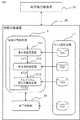
本実施の形態1にかかる治療計画装置20は、一般的な治療計画装置が備えている構成(図示せず)が備わっているのはもちろんのこと、図4に示すように、合成線量分布等の線量分布に関する演算を行う線量分布演算部21と、終了判定シーケンスを実行する終了判定部22と、これら各処理を行うための情報(データ)を記憶するデータ記憶装置23と、を備えている。Next, a treatment planning apparatus that executes the treatment planning method according to the present embodiment will be described with reference to FIGS. 4 and 5.
The
そして、線量分布に関する各処理(第1段階、第2段階、第3段階)は、それぞれ重み係数設定部211、単位照射選定部212、アルゴリズム修正情報生成部213にて実行される。上記重み係数設定部211、単位照射選定部212、アルゴリズム修正情報生成部213、および終了判定部22は、図5に示すように、データ記憶装置23に記憶された情報FR1、FR2、FR3、FR4をそれぞれ適時読み出すとともに、直前の処理で生成された情報(FC1、FC2、FC3、FF1、FF2)を用いて実行処理を行う。 And each process (1st step, 2nd step, 3rd step) regarding dose distribution is performed in the weight
例えば、重み係数設定部211は、合成線量分布が所望の分布と近づくよう単位照射ごとの重み係数を最適化し、その結果得られた単位照射ごとの重み係数の情報FC1を単位照射選定部212に渡す。単位照射選定部212は、受け取った重み係数の情報FC1から、一つの単位照射のピーク位置が変動したときの合成線量分布に発生するコールドスポットの大きさを評価して、一定の位置変動量に対して合成線量分布に発生するコールドスポットの大きさが最も大きい単位照射を特定し、特定した単位照射の情報FC2をアルゴリズム修正情報生成部213に渡す。アルゴリズム修正情報生成部213は、受け取った単位照射の重み係数が小さくなるように最適化手法に加えるべき変更内容(アルゴリズム修正情報)FC3を、重み係数設定部211に渡す。そのため、重み係数設定部211は、一般的な治療計画装置における重み係数の設定機能に、アルゴリズム修正情報に基づいてアルゴリズムを修正する機能を付加したものとなる。 For example, the weighting
また、各段階で生成した情報のうち、終了判定に必要な情報(目標線量分布DObjと生成した合成線量分布DSの情報FF1、単位照射を変動させたときの線量ずれの情報FF2)などは、終了判定部22に随時出力されている。Also, of the information generated at each stage, end information necessary for determination (target dose distribution synthesized dose produced a DObj distribution DS information FF1, dose deviation information FF2 when varying the unit irradiation) etc. Is output to the
上述したように、これら重み係数設定部211、単位照射選定部212、アルゴリズム修正情報生成部213は、実際には、コンピュータ上にプログラムをインストールすることで、これら各部(治療計画作成方法の各段階を実行するモジュール)を構築したものである。そのため、治療計画装置20を構築するCPUおよびメモリ等と物理的に同一のハードウエア内に構築されていてもよい。また、上述した治療計画装置20の構成は、後述する以降の実施の形態に適用できるのは言うまでもない。 As described above, the weight
なお、上述した第2段階においては、単位照射uiの位置変動量をPTVとCTVとの関係(マージンMgn相当)で設定する例について説明したが、必ずしもそれに限られることはない。以下に説明する。 In the second stage described above, the example in which the position variation amount of the unit irradiation ui is set by the relationship between PTV and CTV (corresponding to the margin Mgn) has been described, but the present invention is not necessarily limited thereto. This will be described below.
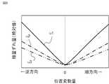
図6は一例として、3つの単位照射u1、u2、u3(図3で示したものとは別)を例にとって、その単位照射uiの位置変動量とそのときのコールドスポットまたはホットスポットにおける線量ずれ量(絶対値)との関係を示したものである。図中、横軸はz方向の位置変動量であり、粒子線Bの進行方向に対して順方向への位置変動を正、逆方向への位置変動を負と定義している。図6からわかるように、単位照射uiの位置変動量と合成線量分布DSv,iでの指示線量Ddに対する線量ずれs(i)との間には線形の関係があり、その比例係数は単位照射uiによって異なるという傾向がある。また、その傾向は位置変動の方向がビーム進行方向と順方向であっても逆方向であっても同様である。FIG. 6 shows, as an example, three unit irradiations u1, u2, and u3 (other than those shown in FIG. 3) as an example, the positional fluctuation amount of the unit irradiation ui, and the dose deviation in the cold spot or hot spot at that time. It shows the relationship with the quantity (absolute value). In the figure, the horizontal axis represents the amount of position fluctuation in the z direction, and the position fluctuation in the forward direction with respect to the traveling direction of the particle beam B is defined as positive, and the position fluctuation in the reverse direction is defined as negative. As can be seen from FIG. 6, there is a linear relationship between the positional fluctuation amount of the unit irradiation ui and the dose deviation s (i) with respect to the indicated dose Dd in the combined dose distribution DSv, i , and the proportionality coefficient is There is a tendency to differ depending on the unit irradiation ui. The tendency is the same regardless of whether the position fluctuation direction is forward or backward with respect to the beam traveling direction.
したがって、ある一定の位置変動量に対する合成線量分布DSv,iに発生するコールドスポットの大きさが最も大きい単位照射ujは、位置変動量の値が異なるときでもコールドスポットの大きさが最も大きくなる単位照射になる。例えば、図6に示される3つの単位照射のなかでは、位置変動量の大きさに関係なく、常に単位照射u1の線量ずれ量が最も大きい。Therefore, the unit irradiation uj having the largest cold spot size generated in the combined dose distribution DSv, i for a certain position variation amount has the largest cold spot size even when the position variation amount value is different. It becomes unit irradiation. For example, among the three unit irradiations shown in FIG. 6, the dose deviation amount of the unit irradiation u1 is always the largest regardless of the magnitude of the position variation.
したがって、変動範囲内のすべての点で計算を行わなくとも、ある適当な一定の位置変動量を決め、その位置変動量に対して合成線量分布DSv,iに発生する線量ずれs(i)が最も大きい単位照射を特定すればよい。そして特定した重み係数Wjを小さく設定しなおすことによって、全体として患者位置の変動量に対する合成線量分布DSv,iに発生するコールドスポットの大きさを小さくすることが可能である。なお、上記の一定の位置変動量を決定する際には、現実にビーム照射中に患者位置がどのくらい動くかを見積もるのが望ましいが、具体的には例えば、非特許文献3に示されるように、5mm以下の値をとるのが妥当であるTherefore, even if calculation is not performed at all points within the variation range, a certain fixed position variation amount is determined, and a dose shift s (i (i) occurring in the combined dose distribution DSv, i with respect to the position variation amount. What is necessary is just to specify the unit irradiation with the largest). And by resetting small specific weighting factors Wj, it is possible to reduce the size of the cold spots that occur as a whole composite dose distribution for the amount of change of the patient position DSv, toi. Note that when determining the above-described constant position fluctuation amount, it is desirable to estimate how much the patient position actually moves during beam irradiation. Specifically, for example, as shown in
以上のように、本実施の形態1にかかる治療計画作成方法によれば、異なる線量分布duiを有する複数の単位照射uiを重ね合わせて放射線治療を行うための治療計画作成方法であって、患部(標的体積=PTV)に対して設定された目標線量分布DObj(例えば、CTV内の線量が指示線量Dd)を近似する合成線量分布DSを生成するために、複数の単位照射uiのそれぞれの重み係数Wiを設定する重み係数設定ステップ(ステップS110)と、複数の単位照射uiのそれぞれに対して、当該単位照射の他の単位照射に対する相対位置を移動させた場合に発生する、目標線量分布DObjからの局所的な線量ずれs(i)(例えばコールドスポット)の大きさを算出し、算出結果に基づいて、例えば、相対位置の移動量が一定の場合に発生する線量ずれs(i)大きな単位照射ujを選定する単位照射選定ステップ(ステップS210、220)と、選定された単位照射ujに設定される重み係数Wjが直前に設定された値よりも小さい値に設定されるように、重み係数設定ステップで用いるアルゴリズムを修正するための修正情報FC3を生成する修正情報生成ステップ(ステップS310)と、を含み、あらかじめ設定された終了条件を満たすまで、上記各ステップが順次繰り返される(終了シーケンスSF10、SF20を有する)ように構成したので、患者位置の変動を測定・モデル化・予測しなくても、患者位置の変動量に対する合成線量分布DSv,iに発生するホットスポットやコールドスポットの大きさを小さくすることができる。そのため従来技術と比べて、患者位置を把握するための測定・モデル化・予測といった処理を行う必要がなく、患者位置の変動を測定する装置や、動きについての情報の入力を省くことができる。また、このような構成によれば、モデル通りではない予期せぬ変動に対してもある程度対応できるという効果がある。As described above, the treatment plan creation method according to the first embodiment is a treatment plan creation method for performing radiotherapy by superimposing a plurality of unit irradiations ui having different dose distributions dui. , the affected area (target volume = PTV) target dose distributionD set forObj (e.g., a dose in the CTV indicated dose Dd) to produce a composite dose distributionD S which approximates a plurality of unit irradiation ui and each of the weighting factor setting step of setting a weight coefficient Wi of (step S110), and occurs when for each of a plurality of unit irradiation ui, moving the relative position to other units irradiation of the unit irradiation The magnitude of the local dose deviation s (i) (for example, a cold spot) from the target dose distribution DObj is calculated, and the amount of movement of the relative position is, for example, one based on the calculation result. A dose deviation s occur if a constant (i) a unit irradiation selection step of selecting a large unit irradiation uj (step S210,220), the weighting coefficient Wj that is set to the selected the unit irradiation uj is set immediately before A correction information generation step (step S310) for generating correction information FC3 for correcting the algorithm used in the weighting factor setting step so as to be set to a value smaller than the set value, and a preset end condition Since the above steps are sequentially repeated until the condition is satisfied (having end sequences SF10 and SF20), the combined dose with respect to the variation amount of the patient position without measuring, modeling, and predicting the variation of the patient position. distribution DSv, it is possible to reduce the size of the hot spots and cold spots occur toi. Therefore, compared with the prior art, it is not necessary to perform processing such as measurement, modeling, and prediction for grasping the patient position, and it is possible to omit an apparatus for measuring fluctuations in the patient position and input of information about movement. Further, according to such a configuration, there is an effect that it is possible to cope with unexpected fluctuations that are not as modeled.
また、本実施の形態1にかかる治療計画装置20によれば、異なる線量分布duiを有する複数の単位照射uiを重ね合わせて放射線治療を行うための治療計画を作成する治療計画装置20であって、患部(標的体積=PTV)に対して設定された目標線量分布DObj(例えば、CTV内の線量が指示線量Dd)を近似する合成線量分布DSを生成するために、複数の単位照射uiのそれぞれの重み係数Wiを設定する重み係数設定部211と、複数の単位照射uiのそれぞれに対して、当該単位照射の当該単位照射の他の単位照射に対する相対位置を移動させた場合に発生する、目標線量分布DObjからの局所的な線量ずれs(i)(例えばコールドスポット)の大きさを算出し、算出結果に基づいて、例えば、相対位置の移動量が一定の場合に発生する線量ずれs(i)が大きな単位照射ujを選定する単位照射選定部212と、選定された単位照射ujに設定される重み係数Wjが直前に設定された値よりも小さい値に設定されるように、重み係数設定部211で用いるアルゴリズムを修正するための修正情報FC3を生成する修正情報生成部(アルゴリズム修正情報生成部213)と、あらかじめ設定された終了条件を満たすまで、線量分布演算部21の各部(211、212、213)部での処理が順次繰り返されるように上記各部を制御する終了判定部22と、を備えるように構成したので、患者位置の変動を測定・モデル化・予測しなくても、患者位置の変動量に対する合成線量分布DSv,iに発生するホットスポットやコールドスポットの大きさを小さくすることができる。そのため従来技術と比べて、患者位置を把握するための測定・モデル化・予測といった処理を行う必要がなく、患者位置の変動を測定する装置や、動きについての情報の入力を省くことができる。また、このような構成によれば、モデル通りではない予期せぬ変動に対してもある程度対応できるという効果がある。Further, according to the
とくに、あらかじめ設定された終了条件は、重み係数設定ステップ(第1段階)あるいは重み係数設定部211における動作において目標線量分布DObjと生成した合成線量分布DSとの差が所定値より大きくなる、および単位照射選定ステップ(第2段階)あるいは単位照射選定部212における動作において線量ずれs(i)の大きさが所定値よりも小さくなる、のうち少なくともいずれか一方である、ように構成したので、合成線量分布DSの所望の線量分布(目標線量分布DObj)からの乖離の抑制、および、ホットスポットやコールドスポットの大きさの所定値以下への抑制の少なくともどちらかを行える。また、処理時間も短縮できる。In particular, preset termination conditions, the difference between the target dose distribution DObj and generated combined dose distribution DS is larger than a predetermined value in operation in the weighting factor setting step (first step) or the weight
また、単位照射選定ステップ(第2段階)あるいは単位照射選定部212における動作では、線量ずれのうち、所望の線量分布(目標線量分布DObj)よりも線量が低くなる線量ずれ(コールドスポット)を線量が高くなる線量ずれ(ホットスポット)より優先して、単位照射ujを選定するようにすれば、臨床的に影響の大きなコールドスポットをより効果的に抑制することができる。Further, in the unit irradiation selection step (second stage) or the operation in the unit
実施の形態2.
上記実施の形態1では、重み係数を修正する対象としてひとつの単位照射を特定する例について説明したが、必ずしもひとつの単位照射に限られることはない。本実施の形態2では、複数の単位照射を選定するようにした。具体的には、「一定の位置変動量に対して合成線量分布に発生するコールドスポットの大きさが大きいほうから順に、あらかじめ決められた個数の単位照射を選定する」、または「一定の位置変動量に対して合成線量分布に発生するコールドスポットの大きさがあらかじめ決められた基準を超えるような単位照射すべて」などの方法が考えられる。
In Embodiment 1 described above, an example in which one unit irradiation is specified as an object for correcting the weighting factor has been described. However, the present invention is not necessarily limited to one unit irradiation. In the second embodiment, a plurality of unit irradiations are selected. Specifically, “select a predetermined number of unit irradiations in descending order of the size of the cold spot generated in the composite dose distribution with respect to a certain amount of position variation” or “a certain position variation. A method such as “all unit irradiations in which the size of the cold spot generated in the composite dose distribution with respect to the quantity exceeds a predetermined standard” can be considered.
この方法では、繰り返しの終了条件を早く満たすという利点がある。この理由を以下に説明する。例えば、一定の位置変動量に対する合成線量分布に発生するコールドスポットの大きさが最も大きい単位照射が単位照射u1で、一定の位置変動量に対する合成線量分布DSvに発生するコールドスポットの大きさが2番目に大きい単位照射が単位照射u2であったような場合、実施の形態1の方法に従うならば、単位照射u1の重み係数W1を小さくするようにアルゴリズム修正情報が生成され、これにしたがって第1段階、第2段階、第3段階を繰り返すうち、あるループで一定の位置変動量に対する合成線量分布DSv,iに発生するコールドスポットの大きさがu1とu2で逆転する可能性が高い。This method has the advantage of satisfying the repetition end condition quickly. The reason for this will be described below. For example, the size of the cold spot size of cold spots that occur in the synthesis dose distribution for a given position variation amount is the largest unit shot in a unit irradiation u1, generated in the synthesis dose distribution DSv for a given position variation amount If there as large units irradiate the second is a unit irradiation u2, if according to the method of the first embodiment, the algorithm correction information so as to reduce the weight coefficient W1 of the unit irradiation u1 is generated, to Thus the first stage, second stage, while repeating the third step, a possibility that the size of the cold spots generated synthesized dose distribution for a given position variation amount in a given loop DSv, thei is reversed at u1 and u2 Is expensive.
逆転した直後の第2段階では一定の位置変動量に対する合成線量分布DSv,iに発生するコールドスポットの大きさが最も大きい単位照射が単位照射u2であると判断され、今度は単位照射u2の重み係数W2を小さくするようにアルゴリズム修正情報が生成される。しかし、本実施の形態2のように、例えば、「一定の位置変動量に対して合成線量分布に発生するコールドスポットの大きさが大きいほうから順に2個の単位照射を選定する」という選定基準を設定しておけば、単位照射u1とu2の重み係数W1、W2を同時に小さくするようにアルゴリズム修正情報が生成されるため、実施の形態1による方法よりも、少ない繰り返し回数で類似の結果が得られ、結果、繰り返しの終了条件を早く満たす。In the second stage immediately after the reversal, it is determined that the unit irradiation u2 having the largest cold spot size in the combined dose distribution DSv, i with respect to a certain amount of position variation is the unit irradiation u2, and this time the unit irradiation u2 algorithm correction information is generated so as to reduce the weight coefficient W2. However, as in the second embodiment, for example, a selection criterion of “selecting two unit irradiations in descending order of the size of the cold spot generated in the combined dose distribution with respect to a certain amount of position variation” is used. Is set, the algorithm correction information is generated so that the weighting factors W1 and W2 of the unit irradiations u1 and u2 are simultaneously reduced. Therefore, similar to the method according to the first embodiment with a smaller number of iterations. A result is obtained, and as a result, the end condition of the repetition is satisfied early.
なお、上記順位付けの際、コールドスポットの線量ずれの値とホットスポットでの線量ずれの値に所定の係数を乗じて重みづけをしたり、一方を無視するようにしたりしてもよいなどは、上述した実施の形態1と同様である。また、選定した順位、あるいは線量ずれの大きさに応じて重み係数Wjの圧縮率に差をつけるようにしてもよい。In the above ranking, the value of the dose deviation at the cold spot and the value of the dose deviation at the hot spot may be weighted by multiplying by a predetermined coefficient, or one may be ignored. This is the same as in the first embodiment described above. Further, the compression rate of the weighting factor Wj may be varied depending on the selected order or the magnitude of the dose deviation.
以上のように、本実施の形態2にかかる治療計画作成方法では、第2段階において複数の単位照射を選定するようにしたので、実施の形態1による方法よりも、少ない繰り返し回数で類似の結果が得られ、結果、処理に必要な時間が短くなる。 As described above, in the treatment planning method according to the second embodiment, since a plurality of unit irradiations are selected in the second stage, similar results can be obtained with a smaller number of repetitions than the method according to the first embodiment. As a result, the time required for processing is shortened.
実施の形態3.
なお、上記実施の形態1、2においては、第2段階において、一定の位置変動量に対して合成線量分布に発生するコールドスポットの大きさによって単位照射を特定した例について説明した。本実施の形態3では、その代わりに、合成線量分布に発生するコールドスポットの大きさがあらかじめ決められた一定値となるときの位置変動量の大きさによって、つまり、位置変動量が最も小さい単位照射ukを特定するようにした。
In the first and second embodiments, the example in which the unit irradiation is specified by the size of the cold spot generated in the composite dose distribution with respect to the constant position fluctuation amount in the second stage has been described. In the third embodiment, instead, the position variation amount is the smallest when the size of the cold spot generated in the composite dose distribution becomes a predetermined constant value, that is, the unit with the smallest position variation amount. The irradiation uk was specified.
具体的には、単位照射uiの位置変動量を、あらかじめ定められたステップで0から順に大きくしていき、合成線量分布DSv,iに発生するコールドスポットの大きさを計算していく。そして、計算したコールドスポットの大きさが、あらかじめ決められた一定値を超えたときの位置変動量が最も小さい単位照射ukを特定するという方法である。Specifically, the position variation amount of the unit irradiation ui, continue sequentially increased from 0 at a predetermined step, synthesis dose distribution DSv, it will calculate the size of the cold spots that occur toi. Then, the unit irradiation uk having the smallest position fluctuation amount when the calculated cold spot size exceeds a predetermined value is specified.
患者の位置変動量が、あらかじめある程度分かっている場合には実施の形態1あるいは2による方法が有効である。しかし、患者の位置変動量は分かっていないが、コールドスポットでの線量不足がどこまで許容されるかの基準が定まっているような場合、本実施の形態3のように、合成線量分布DSv,iに発生するコールドスポットの大きさがあらかじめ決められた一定値となるときの位置変動量が最も小さい単位照射ukを特定し、その単位照射ukの重み係数Wkを小さくするほうが効果的である。The method according to the first or second embodiment is effective when the position variation amount of the patient is known to some extent in advance. However, although not known position variation amount of the patient, if like of criteria doses insufficient cold spots where until the permitted is determined, as in the third embodiment, the synthetic dose distribution DSv , I is more effective when the unit irradiation uk having the smallest positional fluctuation amount when the size of the cold spot generated at the predetermined value is determined in advance and the weight coefficient Wk of the unit irradiation uk is reduced. is there.
なお、上記線量ずれの値について、コールドスポットの上限値とホットスポットでの上限値を変えたり、一方を無視するようにしたりしてもよいなどは、実施の形態1で説明したのと同様である。また、複数の単位照射を選定するようにしてもよいことも実施の形態2と同様である。 As for the dose deviation value, the upper limit value of the cold spot and the upper limit value of the hot spot may be changed or one of them may be ignored, as described in the first embodiment. is there. Further, as in the second embodiment, a plurality of unit irradiations may be selected.
以上のように、本実施の形態3にかかる治療計画作成方法では、単位照射選定ステップ(第2段階)あるいは、単位照射選定部212の動作において、複数の単位照射のうち、線量ずれs(i)の大きさが所定値以上になるときの相対位置の移動量が小さな単位照射ukを選定するように構成したので、患者の位置変動量は不明だが、コールドスポットでの線量不足がどこまで許容されるかの基準が定まっているような場合、効果的である。 As described above, in the treatment plan creation method according to the third exemplary embodiment, in the unit irradiation selection step (second stage) or the operation of the unit
実施の形態4.
実施の形態1においては、単位照射uiを形成する際、図2に示すレンジシフタ15(およびレンジシフタ駆動モジュール17b)を用いて粒子線のエネルギー(飛程)を調整する場合について説明した。本実施の形態4では、ビーム発生装置11の運転パラメータを変更することにより、ビーム発生装置11から出射されるビームのエネルギーを変更することで単位照射uiを形成するようにした。Embodiment 4 FIG.
In the first embodiment, the case where the energy (range) of the particle beam is adjusted using the range shifter 15 (and the range
なお、ビームゲート14およびビームゲート駆動モジュール17aの機能が、照射装置13ではなく、ビーム発生装置11に含まれていても良い。また、エネルギー選択システム(ESS)やリッジフィルタ(RGF)、マルチリーフコリメータ(MLF)等の機器を用いて、単位照射uiを形成しても良いし、あるいはこれらの方法を組み合わせても良い。それぞれの方法により、単位照射uiの形状や、駆動時間、ビーム強度などが変化するので、治療に最も適したものを選択することが可能である。 Note that the functions of the
例えば、ビーム発生装置11の運転パラメータを変更することにより粒子線Bのエネルギーを変更することで単位照射uiを形成した場合、レンジシフタ15を用いて単位照射uiを形成するよりもビームの散乱を抑えることができるというメリットがある反面、粒子線Bのエネルギー変更に時間がかかるというデメリットがある。 For example, when the unit irradiation ui is formed by changing the energy of the particle beam B by changing the operation parameter of the
実施の形態5.
上記各実施の形態にかかる治療計画作成方法および治療計画装置20は、粒子線治療におけるスキャニング照射法に対しても応用が可能である。積層原体照射においてはx、y方向(面方向)には、ほぼ一様な単位照射をz方向(深さ方向)分布のみ変調させて重ね合わせることで合成線量分布DSを形成したが、スキャニング照射における単位照射uiは一般的にはx、y、z方向それぞれにピーク状の線量分布を持つ「スポットビーム」と呼ばれるものであり、これら単位照射uiを3次元的に重ね合わせることで合成線量分布DSを得る技術がスキャニング照射法である。Embodiment 5 FIG.
The treatment plan creation method and
スキャニング照射で得られる単位照射uiの線量分布duiと合成線量分布DSの関係式は、積層原体照射と同様に式(1)で表すことができる。これに対し、スキャニング照射において、ある単位照射(i番目)の位置がずれた時に合成線量分布DSv,i,αに発生するコールドスポットの大きさは、積層原体照射の場合とは異なりx、y、z全ての方向への単位照射uiのずれを考慮しなければならない。したがって、以下の式(6)〜(8)に示すように、単位照射uiの位置ずれのパターンを基本的な6パターンに分解し、それらの影響を合計することで、単位照射uiの位置ずれが合成線量分布DSv,i,αのコールドスポット発生に与える影響を評価する。Relationship of dose distribution dui and synthetic dose distribution DS of the unit irradiation ui obtained by scanning irradiation may be similar to the stacked conformation radiotherapy represented by the formula (1). In contrast, in the scanning irradiation, the size of the cold spots that occur when the shifted position of a unit irradiation (i th) Synthesis dose distribution DSv,i, theα, unlike the case of the stacked conformation radiotherapy The deviation of the unit irradiation ui in all the x, y and z directions must be taken into account. Accordingly, as shown in the following formulas (6) to (8), the positional deviation pattern of the unit irradiation ui is obtained by decomposing the pattern of positional deviation of the unit irradiation ui into six basic patterns and summing the influences thereof. but to assess the impact of synthetic dose distribution DSv,i, in the cold spot occurrence ofα.
Δx0、Δy0、Δz0の値を決定する際は、現実にビーム照射中に患者位置がどのくらい動くかを見積もるのが望ましいが、この場合も、具体的には、例えば、非特許文献3に示されるように、5mm以下の値をとるのが妥当である。When determining the values of Δx0 , Δy0 , and Δz0 , it is desirable to estimate how much the patient position actually moves during beam irradiation, but in this case as well, specifically, for example,
10:粒子線治療装置、 11:ビーム発生装置、 12:ビーム輸送経路、13:照射装置、 14:ビームゲート、 15:レンジシフタ、 16:主制御部、17a:ビームゲート駆動モジュール、 17b:レンジシフタ駆動モジュール、 20:治療計画装置、 21:線量分布演算部、 22:終了判定部、 23:データ記憶装置、 211:重み係数設定部、 213:単位照射選定部、 214:アルゴリズム修正情報生成部(修正情報生成部)。 10: Particle beam therapy device, 11: Beam generation device, 12: Beam transport path, 13: Irradiation device, 14: Beam gate, 15: Range shifter, 16: Main control unit, 17a: Beam gate drive module, 17b: Range shifter drive Module: 20: Treatment planning device, 21: Dose distribution calculation unit, 22: Completion determination unit, 23: Data storage device, 211: Weight coefficient setting unit, 213: Unit irradiation selection unit, 214: Algorithm correction information generation unit (correction) Information generator).
Claims (5)
Translated fromJapanese患部に対して設定された目標線量分布を近似する合成線量分布を生成するために、前記複数の単位照射のそれぞれの重み係数を設定する重み係数設定ステップと、
前記複数の単位照射のそれぞれに対して、当該単位照射の他の単位照射に対する相対位置を移動させた場合に発生する、前記目標線量分布からの局所的な線量ずれの大きさを算出し、算出結果に基づいて、前記複数の単位照射のなかから特定の単位照射として前記線量ずれが最も大きくなる単位照射を選定する単位照射選定ステップと、
前記特定の単位照射に設定される重み係数が、直前に設定された値よりも小さい値に設定されるように、修正情報を生成する修正情報生成ステップと、を含み、
あらかじめ設定された終了条件を満たすまで、上記各ステップが順次繰り返されることを特徴とする治療計画作成方法。A treatment planning method for performing radiotherapy by superimposing a plurality of unit irradiations having different dose distributions,
A weighting factor setting step for setting a weighting factor for each of the plurality of unit irradiations in order to generate a combined dose distribution that approximates the target dose distribution set for the affected area;
For each of the plurality of unit irradiations, calculate the magnitude of a local dose deviation from the target dose distribution that occurs when the relative position of the unit irradiation with respect to other unit irradiations is moved. Based on the result, a unit irradiation selection step for selecting the unit irradiation that maximizes the dose deviation as the specific unit irradiation among the plurality of unit irradiations;
A correction information generating step for generating correction information so that the weighting factor set for the specific unit irradiation is set to a value smaller than the value set immediately before,
A treatment plan creation method, wherein the above steps are sequentially repeated until a preset end condition is satisfied.
患部に対して設定された目標線量分布を近似する合成線量分布を生成するために、前記複数の単位照射のそれぞれの重み係数を設定する重み係数設定部と、
前記複数の単位照射のそれぞれに対して、当該単位照射の他の単位照射に対する相対位置を移動させた場合に発生する、前記目標線量分布からの局所的な線量ずれの大きさを算出し、算出結果に基づいて、前記複数の単位照射のなかから特定の単位照射として前記線量ずれが最も大きくなる単位照射を選定する単位照射選定部と、
前記特定の単位照射に設定される重み係数が、直前に設定された値よりも小さい値に設定されるように、修正情報を生成する修正情報生成部と、
あらかじめ設定された終了条件を満たすまで、上記各部での処理が順次繰り返されるように上記各部を制御する終了条件判定部と、
を備えたことを特徴とする治療計画装置。A treatment planning apparatus for creating a treatment plan for performing radiotherapy by superimposing a plurality of unit irradiations having different dose distributions,
A weighting factor setting unit for setting a weighting factor for each of the plurality of unit irradiations in order to generate a combined dose distribution that approximates the target dose distribution set for the affected area;
For each of the plurality of unit irradiations, calculate the magnitude of a local dose deviation from the target dose distribution that occurs when the relative position of the unit irradiation with respect to other unit irradiations is moved. Based on the result, a unit irradiation selecting unit that selects the unit irradiation that maximizes the dose deviation as the specific unit irradiation from among the plurality of unit irradiations,
A correction information generating unit that generates correction information so that the weighting factor set for the specific unit irradiation is set to a value smaller than the value set immediately before;
An end condition determination unit that controls each unit so that the processing in each unit is sequentially repeated until a preset end condition is satisfied;
A treatment planning apparatus comprising:
Priority Applications (1)
| Application Number | Priority Date | Filing Date | Title |
|---|---|---|---|
| JP2013008023AJP5943847B2 (en) | 2013-01-21 | 2013-01-21 | Treatment plan creation method, treatment plan device |
Applications Claiming Priority (1)
| Application Number | Priority Date | Filing Date | Title |
|---|---|---|---|
| JP2013008023AJP5943847B2 (en) | 2013-01-21 | 2013-01-21 | Treatment plan creation method, treatment plan device |
Publications (2)
| Publication Number | Publication Date |
|---|---|
| JP2014138633A JP2014138633A (en) | 2014-07-31 |
| JP5943847B2true JP5943847B2 (en) | 2016-07-05 |
Family
ID=51415791
Family Applications (1)
| Application Number | Title | Priority Date | Filing Date |
|---|---|---|---|
| JP2013008023AActiveJP5943847B2 (en) | 2013-01-21 | 2013-01-21 | Treatment plan creation method, treatment plan device |
Country Status (1)
| Country | Link |
|---|---|
| JP (1) | JP5943847B2 (en) |
Families Citing this family (2)
| Publication number | Priority date | Publication date | Assignee | Title |
|---|---|---|---|---|
| US9700738B2 (en)* | 2014-06-17 | 2017-07-11 | Intuitive Therapeutics Sa | System and computer program product for radiation inverse treatment planning |
| CN106621071B (en)* | 2015-10-28 | 2024-02-20 | 南京中硼联康医疗科技有限公司 | Treatment planning system based on cloud computing and using method thereof |
Family Cites Families (4)
| Publication number | Priority date | Publication date | Assignee | Title |
|---|---|---|---|---|
| JP3739575B2 (en)* | 1998-10-01 | 2006-01-25 | 三菱電機株式会社 | Synthetic distribution creation parameter search method, apparatus to which the method is applied, and recording medium |
| JP4273502B2 (en)* | 2004-09-24 | 2009-06-03 | 独立行政法人放射線医学総合研究所 | Radiation irradiation equipment |
| JP4877784B2 (en)* | 2006-11-30 | 2012-02-15 | 独立行政法人放射線医学総合研究所 | Irradiation planning apparatus, particle beam irradiation system, and computer program used therefor |
| JP4967686B2 (en)* | 2007-01-26 | 2012-07-04 | 株式会社日立製作所 | Radiotherapy planning apparatus and method for providing radiotherapy planning |
- 2013
- 2013-01-21JPJP2013008023Apatent/JP5943847B2/enactiveActive
Also Published As
| Publication number | Publication date |
|---|---|
| JP2014138633A (en) | 2014-07-31 |
Similar Documents
| Publication | Publication Date | Title |
|---|---|---|
| CN110114117B (en) | Computer system and computer product for radiation therapy planning | |
| US9393443B2 (en) | Treatment planning system | |
| US10328282B2 (en) | System and method for novel chance-constrained optimization in intensity-modulated proton therapy planning to account for range and patient setup uncertainties | |
| US7809107B2 (en) | Method for controlling modulation strength in radiation therapy | |
| US11027147B2 (en) | Knowledge-based spatial dose metrics and methods to generate beam orientations in radiotherapy | |
| EP2038010B1 (en) | Spatially-variant normal tissue objective for radiotherapy | |
| US8009804B2 (en) | Dose calculation method for multiple fields | |
| JP6375097B2 (en) | Radiation treatment planning apparatus and treatment planning method | |
| US9700738B2 (en) | System and computer program product for radiation inverse treatment planning | |
| US11052264B2 (en) | Robust broad beam optimization for proton therapy | |
| JP5909167B2 (en) | Radiation therapy planning device | |
| US20170036037A1 (en) | Optimization methods for radiation therapy planning | |
| CN101247852A (en) | Method and apparatus for planning and delivering radiation therapy | |
| JP2021175513A (en) | Method of selecting beam geometries | |
| CN105617536A (en) | Inverse intensity modulated arc radioterapy optimization method and device | |
| EP3791401A1 (en) | Systems and methods for planning, controlling and/or delivering radiotherapy and radiosurgery using combined optimization of dynamic axes (coda) | |
| JP2023524340A (en) | Generating multiple possible treatment plans for multi-criteria optimization | |
| JP5943847B2 (en) | Treatment plan creation method, treatment plan device | |
| CN105561485A (en) | Radiotherapy treatment planning optimization method and device | |
| de Battisti et al. | An automated optimization tool for high-dose-rate (HDR) prostate brachytherapy with divergent needle pattern | |
| CN109432611B (en) | Method, equipment and storage medium for generating control point of extended dynamic wedge-shaped board | |
| JP2014231020A (en) | Therapeutic device with particle beam | |
| Arsini | Deep learning emulation of physical processes in radiation therapy | |
| WO2024137585A1 (en) | Beam filtration apparatus and method for efficient scanned beam particle arc therapy | |
| Matuszak et al. | Adaptive radiation therapy for lung cancer |
Legal Events
| Date | Code | Title | Description |
|---|---|---|---|
| A621 | Written request for application examination | Free format text:JAPANESE INTERMEDIATE CODE: A621 Effective date:20141128 | |
| A977 | Report on retrieval | Free format text:JAPANESE INTERMEDIATE CODE: A971007 Effective date:20150928 | |
| A131 | Notification of reasons for refusal | Free format text:JAPANESE INTERMEDIATE CODE: A131 Effective date:20151006 | |
| A521 | Request for written amendment filed | Free format text:JAPANESE INTERMEDIATE CODE: A523 Effective date:20151106 | |
| A131 | Notification of reasons for refusal | Free format text:JAPANESE INTERMEDIATE CODE: A131 Effective date:20160112 | |
| A521 | Request for written amendment filed | Free format text:JAPANESE INTERMEDIATE CODE: A523 Effective date:20160205 | |
| TRDD | Decision of grant or rejection written | ||
| A01 | Written decision to grant a patent or to grant a registration (utility model) | Free format text:JAPANESE INTERMEDIATE CODE: A01 Effective date:20160426 | |
| A61 | First payment of annual fees (during grant procedure) | Free format text:JAPANESE INTERMEDIATE CODE: A61 Effective date:20160524 | |
| R151 | Written notification of patent or utility model registration | Ref document number:5943847 Country of ref document:JP Free format text:JAPANESE INTERMEDIATE CODE: R151 | |
| S111 | Request for change of ownership or part of ownership | Free format text:JAPANESE INTERMEDIATE CODE: R313113 | |
| R350 | Written notification of registration of transfer | Free format text:JAPANESE INTERMEDIATE CODE: R350 | |
| S111 | Request for change of ownership or part of ownership | Free format text:JAPANESE INTERMEDIATE CODE: R313111 | |
| R350 | Written notification of registration of transfer | Free format text:JAPANESE INTERMEDIATE CODE: R350 |