JP5942152B2 - Electronics - Google Patents
ElectronicsDownload PDFInfo
- Publication number
- JP5942152B2 JP5942152B2JP2012268921AJP2012268921AJP5942152B2JP 5942152 B2JP5942152 B2JP 5942152B2JP 2012268921 AJP2012268921 AJP 2012268921AJP 2012268921 AJP2012268921 AJP 2012268921AJP 5942152 B2JP5942152 B2JP 5942152B2
- Authority
- JP
- Japan
- Prior art keywords
- panel
- vibration
- amplitude
- electronic device
- connecting portion
- Prior art date
- Legal status (The legal status is an assumption and is not a legal conclusion. Google has not performed a legal analysis and makes no representation as to the accuracy of the status listed.)
- Active
Links
Images


Classifications
- G—PHYSICS
- G06—COMPUTING OR CALCULATING; COUNTING
- G06F—ELECTRIC DIGITAL DATA PROCESSING
- G06F3/00—Input arrangements for transferring data to be processed into a form capable of being handled by the computer; Output arrangements for transferring data from processing unit to output unit, e.g. interface arrangements
- G06F3/01—Input arrangements or combined input and output arrangements for interaction between user and computer
- G06F3/016—Input arrangements with force or tactile feedback as computer generated output to the user
- G—PHYSICS
- G06—COMPUTING OR CALCULATING; COUNTING
- G06F—ELECTRIC DIGITAL DATA PROCESSING
- G06F1/00—Details not covered by groups G06F3/00 - G06F13/00 and G06F21/00
- G06F1/16—Constructional details or arrangements
- G06F1/1613—Constructional details or arrangements for portable computers
- G06F1/1615—Constructional details or arrangements for portable computers with several enclosures having relative motions, each enclosure supporting at least one I/O or computing function
- G06F1/1616—Constructional details or arrangements for portable computers with several enclosures having relative motions, each enclosure supporting at least one I/O or computing function with folding flat displays, e.g. laptop computers or notebooks having a clamshell configuration, with body parts pivoting to an open position around an axis parallel to the plane they define in closed position
- G—PHYSICS
- G06—COMPUTING OR CALCULATING; COUNTING
- G06F—ELECTRIC DIGITAL DATA PROCESSING
- G06F1/00—Details not covered by groups G06F3/00 - G06F13/00 and G06F21/00
- G06F1/16—Constructional details or arrangements
- G06F1/1613—Constructional details or arrangements for portable computers
- G06F1/1633—Constructional details or arrangements of portable computers not specific to the type of enclosures covered by groups G06F1/1615 - G06F1/1626
- G06F1/1684—Constructional details or arrangements related to integrated I/O peripherals not covered by groups G06F1/1635 - G06F1/1675
Landscapes
- Engineering & Computer Science (AREA)
- Theoretical Computer Science (AREA)
- General Engineering & Computer Science (AREA)
- Physics & Mathematics (AREA)
- Computer Hardware Design (AREA)
- Human Computer Interaction (AREA)
- General Physics & Mathematics (AREA)
- Mathematical Physics (AREA)
- User Interface Of Digital Computer (AREA)
- Position Input By Displaying (AREA)
Description
Translated fromJapanese本開示は、ユーザによるタッチ操作に応じて振動等を発生させる電子機器に関する。 The present disclosure relates to an electronic device that generates vibration or the like in response to a touch operation by a user.
表示画面上にタッチパネルが配置された電子機器において、ユーザへの操作性向上のためにタッチパネルを振動させて、ユーザに触覚を与える技術が知られている。タッチパネルに設けた振動部に電圧を印加して、タッチパネルに振動を発生させることによってユーザに触覚を与える(例えば特許文献1参照)。特許文献1では、タブレット型電子機器において触覚を提示する。タブレット型電子機器は、片手で保持するか、机上などに設置することで、タッチパネルに対するタッチ操作が可能である。 In an electronic device in which a touch panel is arranged on a display screen, a technique is known in which a touch panel is vibrated to improve the operability for the user, thereby giving a tactile sensation to the user. A voltage is applied to a vibration part provided on the touch panel to generate vibration on the touch panel, thereby giving a tactile sensation to the user (see, for example, Patent Document 1). In Patent Document 1, a tactile sensation is presented in a tablet electronic device. The tablet electronic device can be touched on the touch panel by holding it with one hand or by installing it on a desk or the like.
本開示は、操作に応じて発生した振動をユーザに安定して提示することができる電子機器を提供する。 The present disclosure provides an electronic device that can stably present vibration generated in response to an operation to a user.
本開示のある実施形態に係る電子機器は、筐体と、情報を表示する表示部と、ユーザがタッチするパネルと、筐体とパネルとを連結する連結部と、パネルを振動させる振動部と、振動部の振動を制御する振動制御部とを備える。振動制御部は、パネルが連結部および連結部以外の支点で支持されているときの振動よりも連結部のみで支持されているときの振動を大きくする。 An electronic apparatus according to an embodiment of the present disclosure includes a housing, a display unit that displays information, a panel that a user touches, a connection unit that connects the housing and the panel, and a vibration unit that vibrates the panel. And a vibration control unit for controlling the vibration of the vibration unit. The vibration control unit increases the vibration when the panel is supported only by the connecting part, rather than the vibration when the panel is supported by the connecting part and a supporting point other than the connecting part.
本開示のある実施形態に係る電子機器によれば、パネルが連結部および連結部以外の支点で支持されているときの振動よりも連結部のみで支持されているときの振動を大きくする。これにより、ユーザに振動を安定して提示することができる。 According to the electronic apparatus according to an embodiment of the present disclosure, the vibration when the panel is supported by only the connecting portion is larger than the vibration when the panel is supported by the fulcrum other than the connecting portion and the connecting portion. Thereby, vibration can be stably presented to the user.
また、ある実施形態に係る電子機器によれば、パネルが水平であるときの振動よりも水平でないときの振動を大きくする。これにより、ユーザに振動を安定して提示することができる。 Moreover, according to the electronic device which concerns on a certain embodiment, the vibration when not horizontal is made larger than the vibration when a panel is horizontal. Thereby, vibration can be stably presented to the user.
また、ある実施形態に係る電子機器によれば、ユーザによるタッチを検出する面側とは反対の面側に加わる圧力が高いときの振動よりも低いときの振動を大きくする。これにより、ユーザに振動を安定して提示することができる。 Moreover, according to the electronic device which concerns on a certain embodiment, a vibration when it is lower than the vibration when the pressure added to the surface side opposite to the surface side which detects a user's touch is high is enlarged. Thereby, vibration can be stably presented to the user.
以下、適宜図面を参照しながら、実施形態を詳細に説明する。但し、必要以上に詳細な説明は省略する場合がある。例えば、既によく知られた事項の詳細説明や実質的に同一の構成に対する重複説明を省略する場合がある。これは、以下の説明が不必要に冗長になるのを避け、当業者の理解を容易にするためである。 Hereinafter, embodiments will be described in detail with reference to the drawings as appropriate. However, more detailed description than necessary may be omitted. For example, detailed descriptions of already well-known matters and repeated descriptions for substantially the same configuration may be omitted. This is to avoid the following description from becoming unnecessarily redundant and to facilitate understanding by those skilled in the art.
なお、発明者らは、当業者が本開示を十分に理解するために添付図面および以下の説明を提供するのであって、これらによって請求の範囲に記載の主題を限定することを意図するものではない。 In addition, the inventors provide the accompanying drawings and the following description in order for those skilled in the art to fully understand the present disclosure, and are not intended to limit the subject matter described in the claims. Absent.
(実施形態1)
電子機器が例えばノートパソコン型の電子機器である場合、タッチパネルはキーボードを備えた筐体と連結部で連結されており、タッチパネルと筐体を開いて机上などに設置して操作する。この状態で操作するとき、タッチパネルを指で押すと電子機器本体が傾いたり、タッチパネルが更に開いたりするなどして安定した操作が困難である。同様に、タブレット型電子機器において、支持が不安定なときは、タッチパネルを指で押すと電子機器本体が傾いたり揺れたりして、安定した操作が困難である。このような状態では、操作に応じてタッチパネルに発生させた振動をユーザに安定して提示することも困難となる。(Embodiment 1)
When the electronic device is, for example, a notebook computer type electronic device, the touch panel is connected to a housing having a keyboard through a connecting portion, and the touch panel and the housing are opened and installed on a desk or the like for operation. When operating in this state, if the touch panel is pressed with a finger, the electronic device main body is tilted or the touch panel is further opened, and thus stable operation is difficult. Similarly, in the tablet electronic device, when the support is unstable, when the touch panel is pressed with a finger, the electronic device main body tilts or shakes, and stable operation is difficult. In such a state, it is difficult to stably present the vibration generated on the touch panel according to the operation to the user.
実施形態に係る電子機器は、例えば、ノートパソコン型の電子機器である。ノートパソコン型の電子機器において、タッチパネルが連結部のみで支持されている状態でタッチ操作をするとき、上述したようにタッチ操作が不安定になる。このタッチパネルが連結部のみで支持されている状態では、タッチパネルの振動を大きくすることで、弱い力でタッチしてもユーザはタッチ操作を行ったことを確実に認識することができる。また、弱い力でもタッチ操作を快適に行うことができるため、必要以上の力でタッチパネルを押すことがなくなり、本体の傾斜を抑制し、安定した操作が可能となる。 The electronic device according to the embodiment is, for example, a notebook personal computer type electronic device. In a notebook personal computer type electronic device, when a touch operation is performed in a state where the touch panel is supported only by the connecting portion, the touch operation becomes unstable as described above. In a state where the touch panel is supported only by the connecting portion, by increasing the vibration of the touch panel, the user can surely recognize that the touch operation has been performed even when touching with a weak force. Further, since the touch operation can be comfortably performed even with a weak force, the touch panel is not pushed with an excessive force, and the tilt of the main body is suppressed, and a stable operation is possible.
<電子機器の全体構成>
図1A、図1B、図2、図3、図4を用いて実施形態に係る電子機器10の全体構成を説明する。<Overall configuration of electronic equipment>
The overall configuration of the
図1Aおよび図1Bは、電子機器10の外観を示す斜視図である。図2は、表示部12の構成を示す図である。図3は振動部13の外観斜視図である。図4は電子機器10の構成を示すブロック図である。 1A and 1B are perspective views illustrating an appearance of the
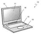
図1Aに示すように、電子機器10において、表示部12の表示面側にはタッチパネル11が組み込まれている。表示部12と筐体14は連結部16で連結されており、表示部12と筐体14は連結部16を回転軸として開閉する。筐体14にはキーボード15が組み込まれている。タッチパネル11は、ユーザのタッチ操作を受け付け、タッチ位置を検出するパネル部材の一例である。連結部16は、表示部12を反転させることも可能となっている。表示部12を反転させて閉じた状態を図1Bに示す。 As shown in FIG. 1A, in the
図2に示すように、表示部12は、表示パネル18、タッチパネル11、振動部13aおよび13b、スペーサ17を備える。振動部13aおよび13bはタッチパネル11に接着されている。タッチパネル11と表示パネル18はスペーサ17を介してそれぞれ接着保持されている。スペーサ17は、例えば、シリコンゴムやウレタンゴム等の緩衝部材である。 As shown in FIG. 2, the
図3に示すように、振動部13は、圧電素子21とシム板22とベース23とを備える。シム板22の裏表に圧電素子21が貼り付けられており、シム板22の両端がベース23に貼り付けられている。ベース23はタッチパネル11に貼り付けられている。 As shown in FIG. 3, the
圧電素子21は、例えば、チタン酸ジルコン酸鉛等の圧電セラミックやニオブ酸リチウム等の圧電単結晶である。圧電素子21は、電圧を印加することにより伸縮する。シム板22の両側に貼り付けられた圧電素子21の片方が伸びて、片方が縮むように制御することで、シム板22にたわみ振動を発生させることができる。振動の周波数としては、100〜400Hz程度の周波数が望ましい。 The
シム板22は、例えば、リン青銅等のバネ部材である。シム板22の振動はベース23を通じてタッチパネル11を振動させ、タッチパネル11を操作しているユーザはタッチパネル11の振動を感知することができる。ベース23は、例えば、アルミや真鍮等の金属や、PETやPP等のプラスチックである。 The
なお、本実施形態では、圧電素子21をシム板22に貼り付けているが、圧電素子21を直接タッチパネル11に貼り付けてもよい。また、タッチパネル11以外の表示部12の部材や筐体14など、電子機器10を構成するいずれかの部材に圧電素子21を直接貼り付けてもよい。また、スパッタリング等の方法によりタッチパネル11に薄膜の透明圧電部材を形成して振動部13として用いてもよい。また、タッチパネル11の上にカバー部材等がある場合は、圧電素子21をカバー部材に貼り付けてもよい。なお、タッチパネル11上にカバー部材がある場合は、タッチパネル11とカバー部材の両方を含めて、タッチ位置を検出するパネル部材とよぶ。また、振動部13として振動モータを用いてもよい。 In this embodiment, the
図4に示すように電子機器10は、表示部12の情報表示を制御する表示制御部32、タッチパネル11の制御を行うタッチパネル制御部31、振動部13の振動を制御する振動制御部33を備える。また電子機器10は、各種の制御を行うマイクロコンピュータ20、各種入出力部37、開閉角度検出部38を備える。 As shown in FIG. 4, the
<個別構成の説明>
表示部12には、文字や数字、アイコンやキーボード等、ユーザからの入力を受け付けるためのものが表示される。ユーザは、表示部12にキーボードが表示されたとき、キーボードの任意の位置をタッチ操作することにより、文字入力等を行うことができる。表示部12として、例えば、液晶方式、有機EL方式、電子ペーパー方式、プラズマ方式などの公知の表示装置を用いることができる。<Description of individual configuration>
The
表示制御部32は、マイクロコンピュータ20によって生成される制御信号に基づいて、表示部12の表示内容を制御する。 The
タッチパネル11は、ユーザのタッチ位置を検知することができる。ユーザのタッチ位置の情報は、タッチパネル制御部31を介してマイクロコンピュータ20に送られる。タッチパネル11として、例えば、静電式、抵抗膜式、光学式、超音波方式、電磁式などのタッチパネルを用いることができる。 The
また、この例では、タッチパネル11と表示パネル18とが別々の構成要素になっているが、タッチパネル11と表示パネル18とは一体に形成されていてもよい。例えば、タッチパネル機能を液晶パネルの内部に一体化するインセル型タッチパネルや、タッチパネル機能を液晶パネルの表面に一体化するオンセル型タッチパネル等の方式であってもよい。 In this example, the
振動部13は、タッチパネル11を振動させる。振動制御部33は、振動部13の振動パターンを制御する。 The
開閉角度検出部38は、連結部16の開閉角度を検出する。これにより、表示部12の開閉状態(タッチパネル11と筐体14との位置関係)を検出することができる。検出した開閉角度の結果は、マイクロコンピュータ20に送られる。マイクロコンピュータ20は検出結果に基づいて振動制御部33の制御パターンを変更する。開閉角度検出部38として、光学式、磁気式、電気抵抗式などの検出手段が用いられる。 The opening / closing
<タッチ入力動作>
図5Aおよび図5Bを用いて、タッチパネル11への入力動作について説明する。<Touch input operation>
An input operation to the
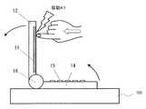
図5Aは電子機器10の表示部12を開いた状態の断面図を示す。図5Bは表示部12を反転させて閉じた状態の断面図を示す。図5Aにおいて表示部12は連結部16のみで支持された状態である。図5Bにおいて、表示部12は、連結部16と、連結部16以外の支点の一例である筐体14で支持された状態である。連結部16以外の支点は電子機器10を載置する机等であってもよい。なお、表示部12を支持するものと表示部12とが面で接している場合でも、本明細書中では支点と表現する。図5Aの状態では、ユーザによるタッチパネル11へのタッチ操作を行うと電子機器10が矢印の方向に傾斜しやすく不安定な状態である。図5Bの状態は、ユーザによるタッチパネル11へのタッチ操作を行っても電子機器10は傾斜せず、安定な状態である。 FIG. 5A is a cross-sectional view of the
図5Aに示すように表示部12を開いた状態でタッチパネル11にタッチして操作するとき、振動部13は振動A1の振動をタッチパネル11に発生させる。図5Bの状態でタッチパネル11にタッチしたとき、振動部13は振動A2の振動をタッチパネル11に発生させる。 As illustrated in FIG. 5A, when the
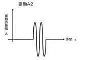
図6Aおよび図6Bは、振動パターンの一例を示す概略図である。マイクロコンピュータ20の命令により、振動制御部33は、振動部13へ図6Aに示すような波形の電圧を印加し、タッチパネル11を振動させることで、ユーザに振動A1を与える。振動A1を与えるための電圧は正弦波で、150Hz、100Vrms、2周期である。このときのタッチパネル11上の振幅は約15μmである。また、振動制御部33が、振動部13へ図6Bに示すような電圧を印加し、タッチパネル11を振動させることで、ユーザに振動A2を与える。振動A2を与えるための電圧は正弦波で、150Hz、33Vrms、2周期である。このときのタッチパネル11上の振幅は約5μmである。開閉角度検出部38の検出結果に基づいて、表示部12が開いている場合は振動A1を発生し、表示部12が閉じている場合は振動A2を発生するようにマイクロコンピュータ20が振動制御部33に命令を送る。 6A and 6B are schematic diagrams illustrating examples of vibration patterns. In response to a command from the
なお、周波数、電圧、周期数に関しては一例であり、矩形波、のこぎり波など、別の波形や、間欠的な波形や、連続的に周波数や振幅が変化する波形などでもよい。なお、ユーザの指に伝わる振動振幅が約5〜50μmとなるように周波数および電圧を設定すると、人間の指に心地良い触覚(振動)を提示することができる。 Note that the frequency, voltage, and number of cycles are merely examples, and other waveforms such as a rectangular wave and a sawtooth wave, an intermittent waveform, and a waveform whose frequency and amplitude continuously change may be used. If the frequency and voltage are set so that the vibration amplitude transmitted to the user's finger is about 5 to 50 μm, a comfortable tactile sensation (vibration) can be presented to the human finger.
振動A2よりも振動A1の振幅を大きくすることで、ユーザがタッチパネル11を弱い力でタッチしても確実に操作することが可能となり、電子機器10の傾斜を緩和して安定したタッチ操作を実現することができる。 By making the amplitude of vibration A1 larger than vibration A2, it becomes possible for the user to operate the
本実施形態によれば、タッチパネルが連結部のみで支持されている状態でタッチ操作するとき、タッチパネルの振動を強くすることで弱い力でタッチしてもユーザがタッチ操作を行ったことを認識することができる。弱い力でタッチ操作を行うことができるため、必要以上の力でタッチパネルを押すことがなくなり、本体の傾斜を抑制し安定した操作が可能となる。また、タッチパネルを反転させて閉じてキーボートと重ねてタッチ操作するとき、タッチパネルは連結部以外の手や机などに安定して支持された状態となる。この状態はユーザがタッチパネルの振動を強く感じ、不快に感じてしまうことがあるため、タッチパネルの振動を弱くすることで快適な触覚をユーザに提示することができる。 According to the present embodiment, when a touch operation is performed in a state where the touch panel is supported only by the connecting portion, it is recognized that the user has performed the touch operation even if the touch is performed with a weak force by increasing the vibration of the touch panel. be able to. Since the touch operation can be performed with a weak force, the touch panel is not pressed with an excessive force, and the tilt of the main body is suppressed and a stable operation is possible. Further, when the touch panel is reversed and closed and touched with the keyboard, the touch panel is stably supported by a hand or a desk other than the connecting portion. In this state, the user may feel the vibration of the touch panel strongly and feel uncomfortable. Therefore, a comfortable tactile sensation can be presented to the user by reducing the vibration of the touch panel.
(実施形態2)
次に、実施形態2に係る電子機器10について説明する。実施形態2に係る電子機器10の構成要素のうち、実施形態1に係る電子機器10と同様の構成要素については同様の参照番号を付して説明の繰り返しを省略する。(Embodiment 2)
Next, the
図7Aおよび図7Bに、実施形態2に係る電子機器10の断面図を示す。電子機器10は、表示部12と筐体14を連結する連結部16を備える。表示部12には、タッチパネル11、傾斜角センサ51aが組み込まれている。筐体14にはタッチパネル111、傾斜角センサ51bが組み込まれている。タッチパネル11、111のそれぞれには、振動部13が設けられている。なお、傾斜角度を検出するセンサとして、例えばジャイロセンサが用いられてもよい。 7A and 7B are cross-sectional views of the
タッチパネル11、111を開いた状態でタッチ操作するとき、タッチパネル11には振動A1を発生させ、タッチパネル111には振動A2を発生させる。 When the touch operation is performed with the
傾斜角センサ51a、51bは、タッチパネル11、111の傾斜角度を検出する。傾斜角センサ51bがタッチパネル111は水平であることを検出した場合、タッチパネル111、筐体14は机100に安定して支持されていると判断し、タッチパネル111には振動A2が発生する。傾斜角センサ51aがタッチパネル11は水平でないことを検出した場合、タッチパネル11は安定して支持されていないと判断し、タッチパネル11には振動A1を発生させる。 The
タッチ操作により傾斜しやすいタッチパネル11の振動を大きくすることで、弱い力でタッチしてもユーザはタッチ操作を行ったことを確実に認識することができる。また、弱い力でもタッチ操作を快適に行うことができるため、必要以上の力でタッチパネル11を押すことがなくなり、本体の傾斜を抑制し、安定した操作が可能となる。また、タッチパネル111は手や机などで安定して支持された状態となる。この状態はユーザがタッチパネルの振動を強く感じ、不快に感じてしまうことがあるため、タッチパネル111の振動を弱くすることで快適な触覚をユーザに提示することができる。 By increasing the vibration of the
なお、電子機器10の載置の仕方が変わり、傾斜角センサ51aがタッチパネル11は水平であることを検出した場合、タッチパネル11には振動A2を発生させる。また、傾斜角センサ51bがタッチパネル111は水平でないことを検出した場合、タッチパネル111には振動A1を発生させる。 When the manner in which the
この例では、タッチパネル11、111の傾斜を傾斜角センサ51a、51bを用いて検出する方法を示したが、表示部12と筐体14の背面に圧力センサを備え、手もしくは机で支持しているかどうかを圧力センサで検出してもよい。 In this example, the method of detecting the tilt of the
図8Aおよび図8Bに、圧力センサ61a、61bを備える電子機器10の断面図を示す。圧力センサ61aは、ユーザによるタッチを検出する面側とは反対の面側に加わる圧力を検出する。この例において、タッチを検出する面側(図のタッチパネル11の右側の面)と反対の面側とは、表示部12の背面(図の左側の面)を指す。また、圧力センサ61bは、ユーザによるタッチを検出する面側とは反対の面側に加わる圧力を検出する。この例において、タッチを検出する面側(図のタッチパネル111の上側の面)と反対の面側とは、筐体14の背面(図の下側の面)を指す。 8A and 8B are cross-sectional views of the
圧力センサ61a、61bは、表示部12と筐体14の背面に加わる圧力を検出する。圧力センサ61aが検出した表示部12の背面に加わる圧力が低い(例えば所定のしきい値未満)場合、タッチパネル11は安定して支持されていないと判断し、タッチパネル11には振動A1を発生させる。圧力センサ61bが検出した筐体14の背面に加わる圧力が高い(例えば所定のしきい値以上)場合、タッチパネル111、筐体14は机100に安定して支持されていると判断し、タッチパネル111には振動A2を発生させる。 The
タッチ操作により傾斜しやすいタッチパネル11の振動を大きくすることで、弱い力でタッチしてもユーザはタッチ操作を行ったことを確実に認識することができる。また、弱い力でもタッチ操作を快適に行うことができるため、必要以上の力でタッチパネル11を押すことがなくなり、本体の傾斜を抑制し、安定した操作が可能となる。また、タッチパネル111は手や机などで安定して支持された状態となる。この状態はユーザがタッチパネルの振動を強く感じ、不快に感じてしまうことがあるため、タッチパネル111の振動を弱くすることで快適な触覚をユーザに提示することができる。 By increasing the vibration of the
なお、電子機器10の載置の仕方が変わり、圧力センサ61aが検出した表示部12の背面に加わる圧力が高い場合、タッチパネル11には振動A2を発生させる。圧力センサ61bが検出した筐体14の背面に加わる圧力が低い場合、タッチパネル111には振動A1を発生させる。 In addition, when the mounting method of the
また、タッチパネルの支持が不安定なとき、タッチ操作時にタッチパネルが揺れることになる。そのような揺れを検出する加速度センサを電子機器10が備え、揺れが所定以上であるときには支持が不安定であると判断してタッチパネルに振動A1を発生させ、所定未満であるときはタッチパネルに振動A2を発生させてもよい。 Further, when the support of the touch panel is unstable, the touch panel is shaken during the touch operation. The
(実施形態3)
次に、実施形態3に係る電子機器10について説明する。実施形態3に係る電子機器10の構成要素のうち、実施形態1に係る電子機器10と同様の構成要素については同様の参照番号を付して説明の繰り返しを省略する。(Embodiment 3)
Next, the
図9は、実施形態3に係る電子機器10の断面図を示す。連結部16からユーザのタッチ位置までの距離をLとすると、ユーザが同じ力でタッチ操作をした場合、距離Lが長くなるほど電子機器10が傾斜しやすくなり、操作が不安定となる。距離Lが短いときの振動よりも長いときの振動を大きくすることで、距離Lが長い位置を弱い力でタッチしてもユーザはタッチ操作を行ったことを確実に認識することができる。また、弱い力でもタッチ操作を快適に行うことができるため、必要以上の力でタッチパネル11を押すことがなくなり、本体の傾斜を抑制し、安定した操作が可能となる。 FIG. 9 is a sectional view of the
タッチパネル11にタッチしたユーザのタッチ位置の情報は、タッチパネル制御部31を介してマイクロコンピュータ20に送られる。マイクロコンピュータ20はタッチ位置と連結部16との間の距離Lを算出し、距離Lに応じた振幅Aを発生する命令を振動制御部33に送り、振動部13を振動させる。図10は、距離Lと振幅Aの関係の一例を示す図である。図10に示すように、距離Lが大きくなるに従って振動部13の振幅Aが大きくなるような振動を発生する。 Information on the touch position of the user touching the
連結部16からタッチ位置までの距離に応じて振動を制御することにより、確実で安定したタッチ入力を実現することが可能となる。 By controlling the vibration in accordance with the distance from the connecting
(その他の実施形態)
以上のように、本出願において開示する技術の例示として、実施形態1〜3を説明した。しかしながら、本開示における技術はこれらに限定されず、適宜、変更、置き換え、付加、省略などを行った実施形態も可能である。また、上記実施形態1〜3で説明した各構成要素を組み合わせて、新たな実施形態とすることも可能である。(Other embodiments)
As described above, Embodiments 1 to 3 have been described as examples of the technology disclosed in the present application. However, the technology in the present disclosure is not limited to these, and embodiments in which changes, replacements, additions, omissions, and the like are appropriately made are possible. Moreover, it is also possible to combine each component demonstrated in the said Embodiment 1-3 and it can be set as a new embodiment.
以下、他の実施形態を例示する。 Hereinafter, other embodiments will be exemplified.
上述の実施形態では、各構成を制御する制御部がそれぞれ設けられていたが、実施形態はこれに限らない。振動制御部33等の各種制御部は、マイクロコンピュータ20が兼ねる構成であってもよい。 In the above-described embodiment, the control unit that controls each component is provided, but the embodiment is not limited thereto. The various control units such as the
上述の実施形態1では、電子機器10の一例としてノートパソコン型の情報端末機器を用いて説明したが、電子機器10はこれには限らない。例えば、タブレット型端末装置、携帯電話、PDA、ゲーム機、カーナビゲーション、ATMなど、タッチパネル11を備える電子機器であってもよい。 In the first embodiment described above, a notebook personal computer type information terminal device has been described as an example of the
上述の実施形態では、タッチパネル11として表示部12の表示面の全面を覆うものを例示したが、これには限らない。例えば、表示面の中央部のみにタッチパネル機能を有し、周辺部はタッチパネル機能を有する部分が覆っていない状態でもよい。 In the above-described embodiment, the
また、ユーザがタッチするパネルとして、表示部12の表示面側に設けられたタッチパネル11を例示して説明したが、パネルはこれに限られない。例えば、タッチパッドのようなポインティングデバイスでもよい。この場合、振動部13は、タッチパッドに設けられており、タッチパッドが安定して支持されているときよりも、支持が不安定な状態のときの振動を大きくする。 Moreover, although the
また、上述の実施形態では、振動を発生することで触覚を提示したが、本開示の技術はこれに限られない。振動以外にも、例えば、静電気による摩擦の変化や、電流による皮膚の刺激、液体による画面形状の変化など、他の方法で触覚を呈示してもよい。触覚の呈示だけでなく、画面表示、音、光、熱などを適宜組み合わせてもよい。 Further, in the above-described embodiment, the tactile sensation is presented by generating vibration, but the technology of the present disclosure is not limited to this. In addition to vibration, for example, a tactile sensation may be presented by other methods such as a change in friction due to static electricity, a skin irritation due to an electric current, and a change in screen shape due to a liquid. In addition to tactile presentation, screen display, sound, light, heat, and the like may be combined as appropriate.
なお、上述した電子機器の動作は、ハードウエアによって実現されてもよいしソフトウエアによって実現されてもよい。そのような制御動作を実行させるプログラムは、例えばマイクロコンピュータ20の内蔵メモリーに記憶される。また、そのようなコンピュータプログラムは、それが記録された記録媒体(光ディスク、半導体メモリー等)から電子機器へインストールしてもよいし、インターネット等の電気通信回線を介してダウンロードしてもよい。 Note that the operation of the electronic device described above may be realized by hardware or software. A program for executing such a control operation is stored in, for example, a built-in memory of the
(まとめ)
実施形態に係る電子機器10は、筐体14と、情報を表示する表示部12と、ユーザがタッチするタッチパネル11と、筐体14とタッチパネル11とを連結する連結部16と、タッチパネル11を振動させる振動部13と、振動部13の振動を制御する振動制御部33とを備える。タッチパネル11が連結部16および連結部16以外の支点で支持されているときの振動よりも、連結部16のみで支持されているときの振動が大きくなるように振動制御部33が振動を制御する。電子機器10によれば、ユーザのタッチ入力時に触覚を確実に与えることで確実な入力を実現するとともに、安定したタッチ入力を実現することができる。(Summary)
The
また、実施形態に係る電子機器10は、筐体14と、情報を表示する表示部12と、ユーザがタッチするタッチパネル11と、タッチパネル11を振動させる振動部13と、振動部13の振動を制御する振動制御部33と、タッチパネル11の傾斜角度を検出する傾斜角センサ51とを備える。タッチパネル11が水平であるときの振動よりもタッチパネル11が水平でないときの振動が大きくなるように振動制御部33が振動を制御する。電子機器10によれば、ユーザのタッチ入力時に触覚を確実に与えることで確実な入力を実現するとともに、安定したタッチ入力を実現することができる。 In addition, the
また、実施形態に係る電子機器10は、筐体14と、情報を表示する表示部12と、ユーザがタッチするタッチパネル11と、タッチパネル11を振動させる振動部13と、振動部13の振動を制御する振動制御部33とを備える。ユーザがタッチパネル11にタッチした位置と連結部16との間の距離に応じて振動制御部33が振動を制御する。例えば、タッチパネル11上のタッチ位置と連結部16との間の距離が短いときの振動よりも長いときの振動を大きくする。電子機器10によれば、ユーザのタッチ入力時に触覚を確実に与えることで確実な入力を実現するとともに、安定したタッチ入力を実現することができる。 In addition, the
また、実施形態に係る電子機器10は、筐体14と、情報を表示する表示部12と、ユーザがタッチするタッチパネル11と、タッチパネル11を振動させる振動部13と、振動部13の振動を制御する振動制御部33と、ユーザによるタッチを検出する面側とは反対の面側に加わる圧力を検出する圧力センサ61とを備える。検出した圧力が高いときの振動よりも低いときの振動を大きくする。電子機器10によれば、ユーザのタッチ入力時に触覚を確実に与えることで確実な入力を実現するとともに、安定したタッチ入力を実現することができる。 In addition, the
また、実施形態に係るコンピュータプログラムは、ユーザがタッチするタッチパネル11と筐体14とが連結部16で連結された電子機器10に振動動作を実行させる。コンピュータプログラムは、タッチパネル11が連結部16および連結部16以外の支点で支持されている状態と連結部16のみで支持されている状態のいずれであるかを検出するステップと、タッチパネル11が連結部16および連結部16以外の支点で支持されているときの振動よりも連結部16のみで支持されているときの振動を大きくするステップとを電子機器10のコンピュータ20に実行させる。実施形態に係るコンピュータプログラムによれば、ユーザのタッチ入力時に触覚を確実に与えることで確実な入力を実現するとともに、安定したタッチ入力を実現することができる。 In addition, the computer program according to the embodiment causes the
また、実施形態に係るコンピュータプログラムは、電子機器10に振動動作を実行させる。コンピュータプログラムは、ユーザがタッチするタッチパネル11の傾斜角度を検出するステップと、タッチパネル11が水平であるときの振動よりも水平でないときの振動を大きくするステップとを電子機器10のコンピュータ20に実行させる。実施形態に係るコンピュータプログラムによれば、ユーザのタッチ入力時に触覚を確実に与えることで確実な入力を実現するとともに、安定したタッチ入力を実現することができる。 In addition, the computer program according to the embodiment causes the
また、実施形態に係るコンピュータプログラムは、ユーザによるタッチを検出するタッチパネル11面側とは反対の面側に加わる圧力を検出するステップと、検出した圧力が高いときの振動よりも低いときの振動を大きくするステップとを電子機器10のコンピュータ20に実行させる。実施形態に係るコンピュータプログラムによれば、ユーザのタッチ入力時に触覚を確実に与えることで確実な入力を実現するとともに、安定したタッチ入力を実現することができる。 In addition, the computer program according to the embodiment detects a pressure applied to a surface opposite to the surface of the
以上のように、本開示における技術の例示として、実施形態を説明した。そのために、添付図面および詳細な説明を提供した。したがって、添付図面および詳細な説明に記載された構成要素の中には、課題解決のために必須な構成要素だけでなく、上記技術を例示するために、課題解決のためには必須でない構成要素も含まれ得る。そのため、それらの必須ではない構成要素が添付図面や詳細な説明に記載されていることをもって、直ちに、それらの必須ではない構成要素が必須であるとの認定をするべきではない。 As described above, the embodiments have been described as examples of the technology in the present disclosure. For this purpose, the accompanying drawings and detailed description are provided. Accordingly, among the components described in the accompanying drawings and the detailed description, not only the components essential for solving the problem, but also the components not essential for solving the problem in order to illustrate the above technique. May also be included. Therefore, it should not be immediately recognized that these non-essential components are essential as those non-essential components are described in the accompanying drawings and detailed description.
また、上述の実施形態は、本開示における技術を例示するためのものであるから、請求の範囲またはその均等の範囲において種々の変更、置き換え、付加、省略などを行うことができる。 Moreover, since the above-mentioned embodiment is for demonstrating the technique in this indication, a various change, substitution, addition, abbreviation, etc. can be performed in a claim or its equivalent range.
本開示は、例えばユーザによるタッチ操作が可能な電子機器に有用である。 The present disclosure is useful, for example, for an electronic device that can be touched by a user.
10 電子機器
11、111 タッチパネル
12 表示部
13a、13b 振動部
14 筐体
15 キーボード
16 連結部
17 スペーサ
18 表示パネル
20 マイクロコンピュータ
21 圧電素子
22 シム板
23 ベース
31 タッチパネル制御部
32 表示制御部
33 振動制御部
37 各種入出力部
38 開閉角度検出部
51 傾斜角センサ
61 圧力センサDESCRIPTION OF
Claims (13)
Translated fromJapaneseユーザがタッチするパネルと、
前記筐体と前記パネルとを連結する連結部と、
前記パネルを振動させる振動部と、
前記振動部の振動を制御する振動制御部と、
を備え、
前記振動制御部は、前記パネルが前記連結部および前記連結部以外の支点で支持されているときの前記パネルの振動の振幅よりも前記連結部のみで支持されているときの前記パネルの振動の振幅が大きくなるように制御する、電子機器。A housing,
And panelYoo over The touches,
A connecting portion for connecting the housing and the panel;
A vibrating section for vibrating the panel;
A vibration control unit for controlling the vibration of the vibration unit;
With
The vibration control unitof the vibrationof the panel when the panel is supported only by the connecting portion thanthe amplitude of vibrationof the panel when supported by the fulcrum other than the connecting portion and the connecting portion Electronic equipmentthat controls theamplitude to increase.
ユーザがタッチするパネルと、
前記筐体と前記パネルとを連結する連結部と、
前記パネルを振動させる振動部と、
前記振動部の振動を制御する振動制御部と、
前記パネルの傾斜角度を検出する角度検出部と、
を備え、
前記振動制御部は、前記パネルが水平であるときの前記パネルの振動の振幅よりも前記パネルが水平でないときの前記パネルの振動の振幅が大きくなるように制御する、電子機器。A housing,
And panelYoo over The touches,
A connecting portion for connecting the housing and the panel;
A vibrating section for vibrating the panel;
A vibration control unit for controlling the vibration of the vibration unit;
An angle detector for detecting an inclination angle of the panel;
With
The vibration control unit is an electronic devicethat controlsthe vibrationamplitude of thepanel when thepanel is not horizontal to be larger thanthe vibrationamplitude of thepanel when thepanel is horizontal.
ユーザがタッチするパネルと、
前記筐体と前記パネルとを連結する連結部と、
前記パネルを振動させる振動部と、
前記振動部の振動を制御する振動制御部と、
ユーザによるタッチを検出する面側とは反対の面側に加わる圧力を検出する圧力検出部と、
を備え、
前記筐体は前記パネルを備え、
前記振動制御部は、前記検出した圧力が高いときの前記パネルの振動の振幅よりも前記検出した圧力が低いときの前記パネルの振動の振幅が大きくなるように制御する、電子機器。A housing,
And panelYoo over The touches,
A connecting portion for connecting the housing and the panel;
A vibrating section for vibrating the panel;
A vibration control unit for controlling the vibration of the vibration unit;
A pressure detector that detects pressure applied to the surface opposite to the surface that detects touch by the user;
With
The housing includes the panel,
The vibration control unit is an electronic apparatusthat controlsthe vibrationamplitude of thepanel when thedetected pressure is lower thanthe vibrationamplitude of thepanel when the detected pressure is high.
前記コンピュータプログラムは、
前記パネルが前記連結部および前記連結部以外の支点で支持されている状態と前記連結部のみで支持されている状態のいずれであるかを検出するステップと、
前記パネルが前記連結部および前記連結部以外の支点で支持されているときの前記パネルの振動の振幅よりも前記連結部のみで支持されているときの前記パネルの振動の振幅が大きくなるように制御するステップと、
を前記電子機器に実行させるコンピュータプログラム。A computer program for causing an electronic device in which a panel touched by a user and a housing are connected by a connecting portion to perform a vibration operation,
The computer program is
Detecting whether the panel is supported by a fulcrum other than the connection part and the connection part or a state supported only by the connection part;
Asthe amplitude of oscillationof the panelbecomes large when it is supported only by the connecting portion thanthe amplitude of vibrationof the panel when the panel is supported by the fulcrum other than the connecting portion and the connecting portionA controlling step;
A computer program that causes the electronic device to execute the program.
前記コンピュータプログラムは、
ユーザがタッチするパネルの傾斜角度を検出するステップと、
前記パネルが水平であるときの前記パネルの振動の振幅よりも前記パネルが水平でないときの前記パネルの振動の振幅が大きくなるように制御するステップと、
を前記電子機器に実行させるコンピュータプログラム。A computer program for causing an electronic device to perform a vibration operation,
The computer program is
Detecting a tilt angle of a panel touched by a user;
Controllingthe vibrationamplitude of thepanel when thepanel is not horizontal to be larger thanthe vibrationamplitude of thepanel when thepanel is horizontal;
A computer program that causes the electronic device to execute the program.
前記コンピュータプログラムは、
ユーザによるタッチを検出するパネル面側とは反対の面側に加わる圧力を検出するステ
ップと、
前記検出した圧力が高いときの前記パネルの振動の振幅よりも前記検出した圧力が低いときの前記パネルの振動の振幅が大きくなるように制御するステップと、
を前記電子機器に実行させるコンピュータプログラム。A computer program for causing an electronic device to perform a vibration operation,
The computer program is
Detecting the pressure applied to the surface side opposite to the panel surface side for detecting touch by the user;
Controllingthe vibrationamplitude of thepanel when thedetected pressure is lower thanthe vibrationamplitude of thepanel when the detected pressure is high;
A computer program that causes the electronic device to execute the program.
ユーザがタッチするパネルと、A panel that the user touches,
前記パネルを振動させる振動部と、A vibrating section for vibrating the panel;
前記振動部の振動を制御する振動制御部と、A vibration control unit for controlling the vibration of the vibration unit;
前記パネルの傾斜角度を検出する角度検出部と、An angle detector for detecting an inclination angle of the panel;
を備え、With
前記筐体は前記パネルを備え、The housing includes the panel,
前記振動制御部は、前記パネルが水平であるときの前記パネルの振動の振幅よりも前記パネルが水平でないときの前記パネルの振動の振幅が大きくなるように制御する、電子機器。The vibration control unit is an electronic device that controls the vibration amplitude of the panel when the panel is not horizontal to be larger than the vibration amplitude of the panel when the panel is horizontal.
ユーザがタッチするパネルと、A panel that the user touches,
前記筐体と前記パネルを連結する連結部と、A connecting portion for connecting the housing and the panel;
前記パネルを振動させる振動部と、A vibrating section for vibrating the panel;
前記振動部の振動を制御する振動制御部と、A vibration control unit for controlling the vibration of the vibration unit;
ユーザによるタッチを検出する面側とは反対の面側に加わる圧力を検出する圧力検出部と、A pressure detector that detects pressure applied to the surface opposite to the surface that detects touch by the user;
を備え、With
前記筐体は前記パネルを備え、The housing includes the panel,
前記振動制御部は、前記検出した圧力が高いときの前記パネルの振動の振幅よりも前記検出した圧力が低いときの前記パネルの振動の振幅が大きくなるように制御する、電子機器。The vibration control unit is an electronic apparatus that controls the vibration amplitude of the panel when the detected pressure is lower than the vibration amplitude of the panel when the detected pressure is high.
Priority Applications (2)
| Application Number | Priority Date | Filing Date | Title |
|---|---|---|---|
| JP2012268921AJP5942152B2 (en) | 2012-01-20 | 2012-12-10 | Electronics |
| US13/740,374US8976139B2 (en) | 2012-01-20 | 2013-01-14 | Electronic device |
Applications Claiming Priority (3)
| Application Number | Priority Date | Filing Date | Title |
|---|---|---|---|
| JP2012009890 | 2012-01-20 | ||
| JP2012009890 | 2012-01-20 | ||
| JP2012268921AJP5942152B2 (en) | 2012-01-20 | 2012-12-10 | Electronics |
Publications (2)
| Publication Number | Publication Date |
|---|---|
| JP2013168134A JP2013168134A (en) | 2013-08-29 |
| JP5942152B2true JP5942152B2 (en) | 2016-06-29 |
Family
ID=48796826
Family Applications (1)
| Application Number | Title | Priority Date | Filing Date |
|---|---|---|---|
| JP2012268921AActiveJP5942152B2 (en) | 2012-01-20 | 2012-12-10 | Electronics |
Country Status (2)
| Country | Link |
|---|---|
| US (1) | US8976139B2 (en) |
| JP (1) | JP5942152B2 (en) |
Cited By (1)
| Publication number | Priority date | Publication date | Assignee | Title |
|---|---|---|---|---|
| JPH068073Y2 (en) | 1986-07-10 | 1994-03-02 | 積水化学工業株式会社 | Prefabricated house roof unit packaging |
Families Citing this family (30)
| Publication number | Priority date | Publication date | Assignee | Title |
|---|---|---|---|---|
| KR101580022B1 (en) | 2011-03-04 | 2015-12-23 | 애플 인크. | Linear vibrator providing localized and generalized haptic feedback |
| US9710061B2 (en) | 2011-06-17 | 2017-07-18 | Apple Inc. | Haptic feedback device |
| US9396629B1 (en) | 2014-02-21 | 2016-07-19 | Apple Inc. | Haptic modules with independently controllable vertical and horizontal mass movements |
| US9594429B2 (en) | 2014-03-27 | 2017-03-14 | Apple Inc. | Adjusting the level of acoustic and haptic output in haptic devices |
| US10133351B2 (en) | 2014-05-21 | 2018-11-20 | Apple Inc. | Providing haptic output based on a determined orientation of an electronic device |
| US9886090B2 (en)* | 2014-07-08 | 2018-02-06 | Apple Inc. | Haptic notifications utilizing haptic input devices |
| US20170024010A1 (en) | 2015-07-21 | 2017-01-26 | Apple Inc. | Guidance device for the sensory impaired |
| JP2017091319A (en)* | 2015-11-12 | 2017-05-25 | 株式会社東海理化電機製作所 | Input device |
| JP2017113691A (en)* | 2015-12-24 | 2017-06-29 | 日本電信電話株式会社 | Pseudokinethetic sense generator |
| KR102516590B1 (en)* | 2016-01-29 | 2023-04-03 | 삼성전자주식회사 | Electronic device and method for executing function according to transformation of display in the electronic device |
| US10772394B1 (en) | 2016-03-08 | 2020-09-15 | Apple Inc. | Tactile output for wearable device |
| US10585480B1 (en) | 2016-05-10 | 2020-03-10 | Apple Inc. | Electronic device with an input device having a haptic engine |
| US9829981B1 (en) | 2016-05-26 | 2017-11-28 | Apple Inc. | Haptic output device |
| US10649529B1 (en) | 2016-06-28 | 2020-05-12 | Apple Inc. | Modification of user-perceived feedback of an input device using acoustic or haptic output |
| US10845878B1 (en) | 2016-07-25 | 2020-11-24 | Apple Inc. | Input device with tactile feedback |
| US10372214B1 (en) | 2016-09-07 | 2019-08-06 | Apple Inc. | Adaptable user-selectable input area in an electronic device |
| JP6551354B2 (en)* | 2016-09-29 | 2019-07-31 | 京セラドキュメントソリューションズ株式会社 | Electronic equipment, vibration control method |
| US10437359B1 (en) | 2017-02-28 | 2019-10-08 | Apple Inc. | Stylus with external magnetic influence |
| US10775889B1 (en) | 2017-07-21 | 2020-09-15 | Apple Inc. | Enclosure with locally-flexible regions |
| US10768747B2 (en) | 2017-08-31 | 2020-09-08 | Apple Inc. | Haptic realignment cues for touch-input displays |
| US11054932B2 (en) | 2017-09-06 | 2021-07-06 | Apple Inc. | Electronic device having a touch sensor, force sensor, and haptic actuator in an integrated module |
| US10556252B2 (en) | 2017-09-20 | 2020-02-11 | Apple Inc. | Electronic device having a tuned resonance haptic actuation system |
| US10768738B1 (en) | 2017-09-27 | 2020-09-08 | Apple Inc. | Electronic device having a haptic actuator with magnetic augmentation |
| US10942571B2 (en) | 2018-06-29 | 2021-03-09 | Apple Inc. | Laptop computing device with discrete haptic regions |
| US10936071B2 (en) | 2018-08-30 | 2021-03-02 | Apple Inc. | Wearable electronic device with haptic rotatable input |
| US10613678B1 (en) | 2018-09-17 | 2020-04-07 | Apple Inc. | Input device with haptic feedback |
| US10966007B1 (en) | 2018-09-25 | 2021-03-30 | Apple Inc. | Haptic output system |
| DE112021000844T5 (en)* | 2020-02-05 | 2022-11-24 | Alps Alpine Co., Ltd. | INPUT DEVICE AND INPUT MODULE |
| US11024135B1 (en) | 2020-06-17 | 2021-06-01 | Apple Inc. | Portable electronic device having a haptic button assembly |
| JP7484803B2 (en)* | 2021-04-29 | 2024-05-16 | 株式会社デンソー | Operating device |
Family Cites Families (21)
| Publication number | Priority date | Publication date | Assignee | Title |
|---|---|---|---|---|
| WO1995002801A1 (en) | 1993-07-16 | 1995-01-26 | Immersion Human Interface | Three-dimensional mechanical mouse |
| JP3949912B2 (en)* | 2000-08-08 | 2007-07-25 | 株式会社エヌ・ティ・ティ・ドコモ | Portable electronic device, electronic device, vibration generator, notification method by vibration and notification control method |
| JP2003272463A (en)* | 2002-03-19 | 2003-09-26 | Clarion Co Ltd | Switch device |
| JP4424729B2 (en) | 2004-02-05 | 2010-03-03 | Smk株式会社 | Tablet device |
| JP4473685B2 (en) | 2004-09-01 | 2010-06-02 | 任天堂株式会社 | GAME DEVICE AND GAME PROGRAM |
| JP2006122164A (en) | 2004-10-27 | 2006-05-18 | Nintendo Co Ltd | Game device and game program |
| JP4358846B2 (en) | 2006-08-15 | 2009-11-04 | 株式会社エヌ・ティ・ティ・ドコモ | Mobile terminal device and operation support method thereof |
| WO2008111493A1 (en)* | 2007-03-13 | 2008-09-18 | Nec Corporation | Mobile terminal, and its function controlling method |
| JP2009009412A (en)* | 2007-06-28 | 2009-01-15 | Canon Inc | Information presenting apparatus and information presenting method |
| JP5204431B2 (en) | 2007-07-09 | 2013-06-05 | ソニー株式会社 | Input device and electronic device with tactile function |
| KR101424259B1 (en)* | 2007-08-22 | 2014-07-31 | 삼성전자주식회사 | Method and apparatus for providing input feedback in portable terminal |
| BRPI0804355A2 (en)* | 2008-03-10 | 2009-11-03 | Lg Electronics Inc | terminal and control method |
| JP2010093516A (en)* | 2008-10-08 | 2010-04-22 | Nec Corp | Mobile information terminal and operation control method for the same, and program |
| JP2010130746A (en)* | 2008-11-26 | 2010-06-10 | Kyocera Corp | Vibration controller and personal digital assistant |
| JP4875050B2 (en)* | 2008-12-09 | 2012-02-15 | 京セラ株式会社 | Input device |
| US8487759B2 (en)* | 2009-09-30 | 2013-07-16 | Apple Inc. | Self adapting haptic device |
| JP5676131B2 (en)* | 2010-04-06 | 2015-02-25 | Necカシオモバイルコミュニケーションズ株式会社 | Portable electronic devices |
| US9417695B2 (en)* | 2010-04-08 | 2016-08-16 | Blackberry Limited | Tactile feedback method and apparatus |
| JP2011227397A (en)* | 2010-04-22 | 2011-11-10 | Canon Inc | Display control unit and display control method |
| JP2011048814A (en)* | 2010-05-06 | 2011-03-10 | Kyocera Corp | Input device |
| JP2011048846A (en)* | 2010-10-27 | 2011-03-10 | Kyocera Corp | Input device and control method for the same |
- 2012
- 2012-12-10JPJP2012268921Apatent/JP5942152B2/enactiveActive
- 2013
- 2013-01-14USUS13/740,374patent/US8976139B2/enactiveActive
Cited By (1)
| Publication number | Priority date | Publication date | Assignee | Title |
|---|---|---|---|---|
| JPH068073Y2 (en) | 1986-07-10 | 1994-03-02 | 積水化学工業株式会社 | Prefabricated house roof unit packaging |
Also Published As
| Publication number | Publication date |
|---|---|
| US8976139B2 (en) | 2015-03-10 |
| JP2013168134A (en) | 2013-08-29 |
| US20130187879A1 (en) | 2013-07-25 |
Similar Documents
| Publication | Publication Date | Title |
|---|---|---|
| JP5942152B2 (en) | Electronics | |
| JP6078935B2 (en) | Electronics | |
| JP6037252B2 (en) | Electronics | |
| JP6265958B2 (en) | System and method for haptic feedback using laterally driven piezoelectric actuators | |
| JP5373236B1 (en) | Electronics | |
| US9342148B2 (en) | Electronic device for generating vibrations in response to touch operation | |
| JP5390029B2 (en) | Electronics | |
| US20140300567A1 (en) | Electronic apparatus | |
| JP6467643B2 (en) | Electronics | |
| JP2012173955A (en) | Electronic apparatus | |
| JP6528086B2 (en) | Electronics | |
| JP5994991B2 (en) | Electronics | |
| KR20120115159A (en) | Tactile feedback method and apparatus | |
| WO2013179821A1 (en) | Touch panel retaining structure | |
| JP2017084404A (en) | Electronic apparatus | |
| JP2014078050A (en) | Electronic apparatus |
Legal Events
| Date | Code | Title | Description |
|---|---|---|---|
| A711 | Notification of change in applicant | Free format text:JAPANESE INTERMEDIATE CODE: A711 Effective date:20141006 | |
| A621 | Written request for application examination | Free format text:JAPANESE INTERMEDIATE CODE: A621 Effective date:20150210 | |
| A977 | Report on retrieval | Free format text:JAPANESE INTERMEDIATE CODE: A971007 Effective date:20151228 | |
| A131 | Notification of reasons for refusal | Free format text:JAPANESE INTERMEDIATE CODE: A131 Effective date:20160126 | |
| A521 | Request for written amendment filed | Free format text:JAPANESE INTERMEDIATE CODE: A523 Effective date:20160324 | |
| TRDD | Decision of grant or rejection written | ||
| A01 | Written decision to grant a patent or to grant a registration (utility model) | Free format text:JAPANESE INTERMEDIATE CODE: A01 Effective date:20160412 | |
| A61 | First payment of annual fees (during grant procedure) | Free format text:JAPANESE INTERMEDIATE CODE: A61 Effective date:20160422 | |
| R151 | Written notification of patent or utility model registration | Ref document number:5942152 Country of ref document:JP Free format text:JAPANESE INTERMEDIATE CODE: R151 | |
| S111 | Request for change of ownership or part of ownership | Free format text:JAPANESE INTERMEDIATE CODE: R313113 | |
| S531 | Written request for registration of change of domicile | Free format text:JAPANESE INTERMEDIATE CODE: R313531 | |
| SZ03 | Written request for cancellation of trust registration | Free format text:JAPANESE INTERMEDIATE CODE: R313Z03 | |
| R350 | Written notification of registration of transfer | Free format text:JAPANESE INTERMEDIATE CODE: R350 | |
| R250 | Receipt of annual fees | Free format text:JAPANESE INTERMEDIATE CODE: R250 | |
| R350 | Written notification of registration of transfer | Free format text:JAPANESE INTERMEDIATE CODE: R350 |