JP5941687B2 - Control device and control method for wind turbine generator facility - Google Patents
Control device and control method for wind turbine generator facilityDownload PDFInfo
- Publication number
- JP5941687B2 JP5941687B2JP2012024247AJP2012024247AJP5941687B2JP 5941687 B2JP5941687 B2JP 5941687B2JP 2012024247 AJP2012024247 AJP 2012024247AJP 2012024247 AJP2012024247 AJP 2012024247AJP 5941687 B2JP5941687 B2JP 5941687B2
- Authority
- JP
- Japan
- Prior art keywords
- output
- wind turbine
- limit
- generator
- calculation unit
- Prior art date
- Legal status (The legal status is an assumption and is not a legal conclusion. Google has not performed a legal analysis and makes no representation as to the accuracy of the status listed.)
- Active
Links
- 238000000034methodMethods0.000titleclaimsdescription7
- 238000004364calculation methodMethods0.000claimsdescription54
- 238000010248power generationMethods0.000claimsdescription40
- 238000003860storageMethods0.000claimsdescription30
- 230000002265preventionEffects0.000claimsdescription18
- 238000012935AveragingMethods0.000claimsdescription5
- 238000009434installationMethods0.000claimsdescription2
- 239000003990capacitorSubstances0.000description22
- 230000000295complement effectEffects0.000description7
- 238000004088simulationMethods0.000description6
- 238000007599dischargingMethods0.000description3
- 238000005259measurementMethods0.000description3
- 235000010724Wisteria floribundaNutrition0.000description2
- 238000010586diagramMethods0.000description2
- 238000004519manufacturing processMethods0.000description2
- 238000007796conventional methodMethods0.000description1
- 230000007423decreaseEffects0.000description1
- 238000009826distributionMethods0.000description1
- 230000000694effectsEffects0.000description1
- 238000005516engineering processMethods0.000description1
- 230000006641stabilisationEffects0.000description1
- 238000011105stabilizationMethods0.000description1
- 239000013589supplementSubstances0.000description1
Images


Classifications
- Y—GENERAL TAGGING OF NEW TECHNOLOGICAL DEVELOPMENTS; GENERAL TAGGING OF CROSS-SECTIONAL TECHNOLOGIES SPANNING OVER SEVERAL SECTIONS OF THE IPC; TECHNICAL SUBJECTS COVERED BY FORMER USPC CROSS-REFERENCE ART COLLECTIONS [XRACs] AND DIGESTS
- Y02—TECHNOLOGIES OR APPLICATIONS FOR MITIGATION OR ADAPTATION AGAINST CLIMATE CHANGE
- Y02E—REDUCTION OF GREENHOUSE GAS [GHG] EMISSIONS, RELATED TO ENERGY GENERATION, TRANSMISSION OR DISTRIBUTION
- Y02E10/00—Energy generation through renewable energy sources
- Y02E10/70—Wind energy
- Y02E10/72—Wind turbines with rotation axis in wind direction
- Y—GENERAL TAGGING OF NEW TECHNOLOGICAL DEVELOPMENTS; GENERAL TAGGING OF CROSS-SECTIONAL TECHNOLOGIES SPANNING OVER SEVERAL SECTIONS OF THE IPC; TECHNICAL SUBJECTS COVERED BY FORMER USPC CROSS-REFERENCE ART COLLECTIONS [XRACs] AND DIGESTS
- Y02—TECHNOLOGIES OR APPLICATIONS FOR MITIGATION OR ADAPTATION AGAINST CLIMATE CHANGE
- Y02E—REDUCTION OF GREENHOUSE GAS [GHG] EMISSIONS, RELATED TO ENERGY GENERATION, TRANSMISSION OR DISTRIBUTION
- Y02E70/00—Other energy conversion or management systems reducing GHG emissions
- Y02E70/30—Systems combining energy storage with energy generation of non-fossil origin
Landscapes
- Wind Motors (AREA)
Description
Translated fromJapanese本発明は風車発電設備の制御装置及び制御方法に関する。 The present invention relates to a control device and a control method for wind turbine power generation equipment.
非特許文献1には、二次電池とキャパシタを電力貯蔵要素として備える風車発電設備の制御装置が開示されている。 Non-Patent
非特許文献1に記載の制御装置は主に大型風車用であり、比較的長周期(1〜24時間程度)の出力変動の平準化のために、電力貯蔵要素としての二次電池とキャパシタは大容量のものを採用する必要がある。電力貯蔵要素が大型であると、製造等がコスト高となる。また、非特許文献1を含め風車発電に関する従来の技術では、中周期(例えば1〜20分程度)の出力変動の効率的な平準化は困難であった。以上の点で、従来の風車発電に関する技術は、例えば100kWクラスの規模の風車発電設備の制御には適していなかった。 The control device described in Non-Patent
風速によって平準化目標出力を算出し、この平準化目標出力に合わせて系統出力制御を行うことが考えられる。しかし、この方法では、風速の変動に伴う風車出力の変動を全て電力貯蔵要素が吸収すると、電力貯蔵要素の容量が大きくなり、費用が増大する。また、蓄電装置の充放電回数が多いため、寿命が短くなる。さらに、蓄電装置への充放電による損失が充放電量に比例して増大するという問題がある。 It is conceivable that the leveling target output is calculated based on the wind speed, and the system output control is performed in accordance with the leveling target output. However, in this method, if the power storage element absorbs all the fluctuations in the wind turbine output accompanying the fluctuations in the wind speed, the capacity of the power storage element increases and the cost increases. In addition, since the power storage device is charged and discharged many times, the life is shortened. Furthermore, there is a problem that the loss due to charging / discharging of the power storage device increases in proportion to the amount of charging / discharging.
本発明は、風車発電設備において、電力貯蔵要素の充放電を減少し、電力貯蔵要素の小容量化による低コスト化、電力貯蔵要素の高寿命化、及び充放電による損失の低減を目的とする。また、本発明は、風車発電設備において、中周期(例えば1〜20分程度)の出力変動の効率的な平準化を課題とする。 An object of the present invention is to reduce charge / discharge of a power storage element in a wind turbine power generation facility, to reduce the cost by reducing the capacity of the power storage element, to extend the life of the power storage element, and to reduce loss due to charge / discharge. . Another object of the present invention is to efficiently level output fluctuations in a medium cycle (for example, about 1 to 20 minutes) in a wind turbine power generation facility.
本発明の第1の態様は、
ピッチを制御可能であって発電機に連結された風車と、前記発電機と系統の間に介在するインバータと、前記発電機により充電可能かつ前記系統へ放電可能な電力貯蔵要素とを備える風車発電設備の制御装置であって、
前記電力貯蔵要素の目標電力蓄積量に対する容量率を検出する容量率測定器と、
風速によって定まる理論出力を移動平均により平均化した平均化出力に低減率を乗じた風車出力変動の下限値を、前記風車の発電機の出力の制限値である風車出力制限として算出する風車出力制限算出部と、
前記理論出力を前記容量率に基づいて補正し、前記系統への出力の制限値である系統出力制限を算出する系統出力制限算出部と、
前記風車の発電機の出力が前記風車出力制限を越えないように、かつ前記系統への出力が前記系統出力制限を越えないように前記インバータを制御するインバータ制御部と、
風速又は風車出力制限によって定まる目標回転数を維持するように、前記風車のピッチを制御するピッチ制御部と
を備える。
The first aspect of the present invention is:
Wind turbine power generation comprising a wind turbine capable of controlling the pitch and connected to a generator, an inverter interposed between the generator and a system, and a power storage element that can be charged by the generator and discharged to the system A control device for equipment,
A capacity ratio measuring device for detecting a capacity ratio with respect to a target power storage amount of the power storage element;
Wind turbine output limit that calculates the lower limit value of the wind turbine output fluctuation, which is the average output obtainedby averaging the theoretical output determined by the wind speed bymoving average , multiplied by the reduction rate, as the wind turbine output limit that is the limit value of the output of the wind turbine generator A calculation unit;
A system output limit calculation unit that corrects the theoretical output based on the capacity ratio and calculates a system output limit that is a limit value of the output to the system;
An inverter control unit for controlling the inverter so that the output of the wind turbine generator does not exceed the wind turbine output limit and the output to the grid does not exceed the grid output limit;
A pitch control unit that controls the pitch of the wind turbine so as to maintain the target rotational speed determined by the wind speed or the wind turbine output limitation.
この構成により、風速から風車出力変動の下限値を予測し、風車出力変動の下限値を風車出力制限値として制御するため、風車出力が下限値を下回ると、電力貯蔵要素への充電を行わずに、電力貯蔵要素から放電するので、電力貯蔵要素の充放電回数が減少する。 With this configuration, the lower limit value of the wind turbine output fluctuation is predicted from the wind speed, and the lower limit value of the wind turbine output fluctuation is controlled as the wind turbine output limit value.If the wind turbine output falls below the lower limit value, the power storage element is not charged. In addition, since the power storage element is discharged, the number of charge / discharge cycles of the power storage element is reduced.
前記風車出力制限算出部は、前記低減率を風車設置場所の乱流強度により算出することが好ましい。 It is preferable that the windmill output restriction calculation unit calculates the reduction rate based on turbulence intensity at a windmill installation location.
系統出力の変動が定格出力の所定範囲内となるように、系統出力の上限と下限を算出し、前記系統出力の上限と下限を前記系統出力制限算出部に入力する逸脱防止演算部をさらに備え、
前記系統出力制限算出部は、系統出力が上限以上の時には、前記インバータ及びピッチ制御で風車出力を制限し、系統出力が下限以下では、前記電力貯蔵要素から放電し、逸脱を防止する、ことが好ましい。The system further includes a deviation prevention calculation unit that calculates an upper limit and a lower limit of the system output so that fluctuations in the system output are within a predetermined range of the rated output, and inputs the upper and lower limits of the system output to the system output limit calculation unit. ,
The grid output limit calculation unit limits the wind turbine output by the inverter and pitch control when the grid output is equal to or higher than the upper limit, and discharges from the power storage element to prevent deviation when the grid output is equal to or lower than the lower limit. preferable.
本発明の第2の態様は、ピッチを制御可能であって発電機に連結された風車と、前記発電機と系統の間に介在するインバータと、前記発電機により充電可能かつ前記系統へ放電可能な電力貯蔵要素とを備える風車発電設備の制御方法であって、
前記電力貯蔵要素の目標電力蓄積量に対する容量率を検出し、
風速によって定まる理論出力を移動平均により平均化した平均化出力に低減率を乗じた風車出力変動の下限値を、前記風車の発電機の出力の制限値である風車出力制限として算出し、
前記理論出力を前記容量率に基づいて補正し、前記系統への出力の制限値である系統出力制限を算出し、
前記風車の発電機の出力が前記風車出力制限を越えないように、かつ前記系統への出力が前記系統出力制限を越えないように前記インバータを制御し、
風速又は風車出力制限によって定まる目標回転数を維持するように、前記風車のピッチを制御する。
According to a second aspect of the present invention, a wind turbine capable of controlling the pitch and connected to a generator, an inverter interposed between the generator and the system, chargeable by the generator, and dischargeable to the system A wind turbine power plant control method comprising a power storage element,
Detecting a capacity ratio with respect to a target power storage amount of the power storage element;
The lower limit value of the wind turbine output fluctuation obtained by multiplying the average output obtainedby averaging the theoretical output determined by the wind speed by themoving average and the reduction rate is calculated as a wind turbine output limit that is a limit value of the output of the wind turbine generator,
Correcting the theoretical output based on the capacity ratio, calculating a system output limit that is a limit value of the output to the system,
Controlling the inverter so that the output of the wind turbine generator does not exceed the wind turbine output limit and the output to the system does not exceed the system output limit;
The pitch of the windmill is controlled so as to maintain the target rotational speed determined by the wind speed or the windmill output limit.
本発明の風車発電設備の制御装置及び制御方法によれば、風速から予測した風車出力変動の下限値を風車出力制限値として制御するため、電力貯蔵要素の充放電回数が減少し、電力貯蔵要素として比較的小容量のもの(例えば小容量のキャパシタ)を採用でき、それによって製造等のコストを低減できる。また、電力貯蔵要素の充放電回数の減少により、電力貯蔵要素の高寿命化、及び損失の低減を図ることができる、さらに、また、中周期(例えば1〜20分程度)の出力変動を効果的に抑制できる。 According to the control apparatus and the control method for wind turbine power generation equipment of the present invention, the lower limit value of the wind turbine output fluctuation predicted from the wind speed is controlled as the wind turbine output limit value. As such, a capacitor having a relatively small capacity (for example, a capacitor having a small capacity) can be employed, thereby reducing the manufacturing cost. In addition, by reducing the number of times of charging / discharging the power storage element, it is possible to increase the life of the power storage element and reduce the loss. Furthermore, the output fluctuation in the middle period (for example, about 1 to 20 minutes) is also effective. Can be suppressed.
次に、添付図面を参照して本発明の実施形態を詳細に説明する。 Next, embodiments of the present invention will be described in detail with reference to the accompanying drawings.
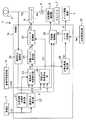
図1及び図2を参照すると、風車発電設備1の風車2は、ピッチ調整機構3によってピッチ角θを調整可能なロータ2aを有する。また、風車2は発電機4に連結され、発電機4と系統5の間にはインバータ6が介在している。インバータ6は風車2の回転により発電機4が発生する交流電力を直流電力に一旦変換した後に、系統5と同周波数の交流電力に変換する。また、インバータ6には、系統5への出力(系統出力Pg)の平準化に使用されるキャパシタ7(電力貯蔵要素)が充放電制御回路8を介して接続されている。キャパシタ7は充放電制御回路8により、発電機4の発生する電力によって充電される状態、蓄積した電力をインバータ6を介して系統5へ放電する状態、及び充放電のいずれも行わない保持状態のいずれかの状態とされる。 Referring to FIGS. 1 and 2, the
風車2のロータ2aへの風速Vdを測定する風速計11が設けられている。また、風車2の回転数Ndを検出する回転数検出器12が設けられている。さらに、キャパシタ7が実際に充電されている容量の充電目標(例えばキャパシタ7の定格容量)に対する割合(容量率Ccap(%))を検出する容量率測定回路13が設けられている。 An
制御部15は、風速計11から入力される風速Vd、回転数検出器12から入力される回転数Nd、及び容量率測定回路13から入力される容量率Ccapを用いて、インバータ6、キャパシタ7の充放電制御回路8、及びピッチ調整機構3を制御する。後述するように、インバータ6の制御とピッチ調整機構3を介したロータ2aのピッチ角θの制御により風車2の発電機4の出力及び回転数が制御される。また、インバータ6の制御によって系統出力Pgが制御される。 The
図2に示すように、制御部15は、乱流強度・低減率算出部21、理論出力算出部22、風車出力制限算出部23、発電トルク算出部24、系統出力制限算出部25、及び目標回転数算出部26を備える。また、制御部15はインバータ6を制御するインバータ制御部27、充放電制御回路8を制御する充放電制御部28、及びピッチ調整機構3を制御するピッチ制御部29、逸脱防止演算部30を備える。 As shown in FIG. 2, the
次に、制御部15により実行されるインバータ6、キャパシタ7の充放電制御回路8、及びピッチ調整機構3の制御を詳細に説明する。 Next, the control of the
まず、風車2の発電機4の出力の制御について説明する。なお、図2においてPwは制御しなかった場合の風車2の発電機4の出力(風車出力)を示す。 First, control of the output of the
乱流強度・低減率算出部21は、以下の式(1)を使用して、風速計11から入力される測定された風速Vdから風速の標準偏差Vstdと平均風速Vaを求めて、これらから乱流強度Tiを算出する。次に、乱流強度・低減率算出部21は、以下の式(2)を使用して、乱流強度Tiから風車出力制限算出部23で使用する低減率Kdを算出する。例えば、乱流強度が15%の場合、低減率は0.61となる。 The turbulence intensity / reduction

乱流強度・低減率算出部21で算出された低減率Kdは、風車出力制限算出部23に出力される。 The reduction rate Kd calculated by the turbulence intensity / reduction
理論出力算出部22は、風速Vdを使用して理論出力Ptを算出する。この理論出力Ptは風車2が受ける風の平均的なエネルギーを表すものであり、インバータ6を制御する際の目標(目標出力)である。本実施形態では、理論出力算出部22は、以下の式(3)に基づいて理論出力Ptを算出する。 The theoretical
理論出力算出部22で算出された理論出力Ptは風車出力制限算出部23、系統出力制限算出部25及び充放電制御部28に出力される。 The theoretical output Pt calculated by the
目標回転数算出部26は、風車出力制限算出部23で算出される風車出力Pcを使用して風車2aの目標回転数Ntを算出する。この目標回転数Ntはロータ2aのピッチ角θを制御する際の目標となる。本実施形態における目標回転数算出部26は、以下の式(4に基づいて目標回転数Ntを算出する。 The target rotational
目標回転数算出部26で算出された目標回転数Ntは、ピッチ制御部29に出力される。 The target rotational speed Nt calculated by the target rotational
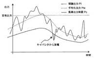
風車出力制限算出部23には、理論出力算出部22から理論出力Ptが入力され、乱流強度・低減率算出部21から低減率Kdが入力される。風車出力制限算出部23は、以下の式(5)のように、理論出力Ptを1分移動平均により平均化した平均化出力Ptaに低減率Kdを乗じて、風車2の発電機4の出力変動の下限値である風車出力制限Pcを算出する。図3は、理論出力Pt、平均化出力Pta、風車出力制限Pcの一例を示す。風車出力制限Pc、すなわち低減率Kdを考慮した理論出力Ptが実際にインバータ6を制御する際の目標となる。 The wind turbine output
風車出力制限算出部23で算出された風車出力制限Pcは、発電トルク算出部24に出力される。 The windmill output limit Pc calculated by the windmill output
発電トルク算出部24は、風車出力制限Pcを発電トルクTgに換算する。発電トルクTgは、風車2が発電機4を回転させようとするのに対してインバータ6が発生する抵抗トルクである。本実施形態における発電トルク算出部24は、以下の式(6)に基づいて発電トルクTgを算出する。 The power generation
発電トルク算出部24で算出された発電トルクTgは、インバータ制御部27に出力される。 The power generation torque Tg calculated by the power generation
インバータ制御部27は、発電トルクTgを発電トルク算出部24で算出された値となるようにインバータ6を制御する。つまり、インバータ制御部7は、風車2の発電機4の出力が、風車出力制限Pc以下、つまり理論出力Ptに低減率Kdを乗じた出力変動の下限値以下とならないように、インバータ6を制御する。 The
ピッチ制御部29には、目標回転数算出部26で算出された目標回転数Ntが入力されると共に、回転数検出器12が検出した風車2の回転数Ndが入力される。前述のようにインバータ制御部27は、発電トルクTgが風車出力制限Pc以下に相当する値とならないようにインバータ6を制御する。もし仮に、このインバータ制御部27によるインバータ6の制御に対して、ロータ2aのピッチ角θを調整しないとすると、風車2に入力される風のエネルギーが過大となる。そこでピッチ制御部29はピッチ角θを調整することで風車2に入力される風のエネルギーを抑制する。具体的には、ピッチ制御部29は、回転数検出器12で検出された回転数Ndが目標回転数Ntに維持されるようにピッチ調整機構3によってロータ2aのピッチ角θを制御する。 The
以上のように、インバータ制御部27のインバータ6の制御(インバータ制御)と、ピッチ調整機構3を介してピッチ調整部29によるロータ2aのピッチ角θの制御(ピッチ制御)とにより、風車2の発電機4の出力が風車出力制限Pc以下にならないように制御される。
また、乱流強度により求めた低減率で出力制限することにより、図4に示すように、理論出力の正規分布の標準偏差−σより大きい場合、約84%の平準化運転を行うことができる。As described above, the
Further, by limiting the output with the reduction rate obtained by the turbulent intensity, as shown in FIG. 4, when the standard deviation of the normal distribution of the theoretical output is larger than the standard deviation −σ, the leveling operation of about 84% can be performed. .
次に、系統出力Pgの逸脱防止制御について説明する。 Next, deviation prevention control of the system output Pg will be described.
逸脱防止演算部30には、インバータ6出口の系統出力Pgが入力される。逸脱防止演算部30は、図5に示すように、10分間の系統出力Pgの1分間平均値から、系統出力の変動が定格出力の10%以内となるように、出力範囲(上限と下限)を算出する。
系統出力制限算出部25には、理論出力算出部22から理論出力Ptが入力され、逸脱防止演算部30から系統出力Pgの上限値と下限値が入力される。
系統出力制限算出部25は、系統出力Pgが上限以上の時には、前述のインバータ及びピッチ制御で風車出力を制限する。系統出力Pgが下限以下では、キャパシタ7から放電し、逸脱を防止する。The system output Pg at the outlet of the
The system output
When the system output Pg is equal to or higher than the upper limit, the system output
次に、キャパシタ7の充放電の制御について説明する。 Next, charge / discharge control of the capacitor 7 will be described.
充放電制御部28には、理論出力算出部22から理論出力Ptが入力され、容量率測定回路13から容量率Ccapが入力される。 The charge /
容量率Ccapが閾値Ccapthを上回る場合(キャパシタ7が十分に充電されている場合)には、充放電制御部28は、系統出力Pgが理論出力Ptとなるように、充放電制御回路8によりキャパシタ7を充放電させる。この場合、風車2の発電機4の出力の短時間減少時にキャパシタ7が放電し理論出力Ptに対する系統出力Pgの不足分を補う。 When the capacity ratio Ccap exceeds the threshold Ccapth (when the capacitor 7 is sufficiently charged), the charge /
一方、容量率Ccapが閾値Ccapth以下の場合(キャパシタ7が十分に充電されていない場合)、充放電制御部28は、系統出力Pgにかかわらず、つまり系統出力Pgが理論出力Ptを下回っていているか否かにかかわらず、充放電制御回路8によりキャパシタ7を充電させる。 On the other hand, when the capacity ratio Ccap is equal to or less than the threshold value Ccapth (when the capacitor 7 is not sufficiently charged), the charge /
以上の制御の結果、キャパシタ7が少容量であっても、中周期(例えば1〜20分程度)の系統出力Pgの変動を効果的に抑制できる。 As a result of the above control, even if the capacitor 7 has a small capacity, fluctuations in the system output Pg in the middle period (for example, about 1 to 20 minutes) can be effectively suppressed.
表1は、3台のファーム風車を用い、キャパシタの無いパターンAと、3台のファーム風車を用いるとともに、容量が300Wh/台のキャパシタを用いた風車発電設備のパターンB〜Eにおいて、シミュレーションによりファーム補完制御、逸脱防止制御、系統出力制限制御、及び本願発明の発電機出力制限制御の各種制御を行った場合の逸脱率及び発電量を比較したものである。ファーム補完制御は、例えば3台の風車中、1台が逸脱した場合、出力制限を解除し、2台で発電の不足分を補うものである。逸脱防止制御、系統出力制御、発電許出力制限制御は既に述べた通りである。 Table 1 shows the simulation results for patterns B to E of a wind turbine power generation facility using three farm wind turbines, a pattern A without a capacitor, and three farm wind turbines, and a capacitor having a capacity of 300 Wh / unit. This is a comparison of the deviation rate and the amount of power generation when various controls of the farm complement control, deviation prevention control, system output restriction control, and generator output restriction control of the present invention are performed. For example, when one of the three wind turbines deviates, the farm supplement control cancels the output restriction, and the two units compensate for the shortage of power generation. Deviation prevention control, system output control, and power generation permission output restriction control are as described above.
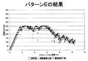
パターンAは、ファーム補完制御、逸脱防止制御、系統出力制限制御、発電機出力制限制御のいずれも行わなかった。パターンBは、ファーム補完制御と逸脱防止制御のみを行い、パターンCは、ファーム補完制御、逸脱制御及び系統出制限制御を行い、パターンDは、ファーム補完制御、逸脱防止制御、及び低減率を60%とした発電機出力制限制御を行い、パターンEはファーム補完制御と逸脱防止制御を行うとともに、低減率を実測した乱流強度から演算した発電機出力制限制御を行った。 In pattern A, neither firm complement control, departure prevention control, system output limit control, or generator output limit control was performed. Pattern B performs only firm complement control and departure prevention control, Pattern C performs firm complement control, departure control, and system output restriction control, and Pattern D provides firm complement control, departure prevention control, and reduction rate of 60. %, Generator output limit control was performed for pattern E, while farm complement control and deviation prevention control were performed, and generator output limit control was calculated from the turbulence intensity measured for the reduction rate.
パターンAでは、ファーム補完制御、逸脱防止制御、系統出力制限制御、発電機出力制限制御のいずれも行わなかったので、逸脱率は54.3%であるが、発電量は最大であった。図6に系統出力の測定値の結果を示す。
パターンBでは、逸脱防止制御により、出力可能範囲の上限以上とならないように制御を行うことで、逸脱率17.5%を達成できた。図7に系統出力の測定値の結果を示す。
パターンCでは、逸脱防止制御と系統出力制限により、逸脱率10.0%を達成できたが、発電量は低かった。図8に系統出力の測定値の結果を示す。
パターンDでは、低減率を60%とした発電機出力制限制御により、各風車のキャパシタのみで、逸脱率5.1%を達成できた。しかし、パターンDは、パターンAに比べて発電量が77%まで低減した。図9に系統出力の測定値の結果を示す。
パターンEでは、実測した乱流強度から低減率を演算して発電機出力制限制御を行うことで、逸脱率11%を達成でき、しかも83%の発電量を確保できた。図10に系統出力の測定値の結果を示す。In pattern A, none of the farm complement control, deviation prevention control, system output restriction control, and generator output restriction control was performed, so the deviation rate was 54.3%, but the power generation amount was the maximum. FIG. 6 shows the result of the measured value of the system output.
In pattern B, the deviation rate of 17.5% was achieved by performing control so as not to exceed the upper limit of the output possible range by deviation prevention control. FIG. 7 shows the result of the measured value of the system output.
In Pattern C, a departure rate of 10.0% was achieved by departure prevention control and system output restriction, but the power generation amount was low. FIG. 8 shows the result of the measured value of the system output.
In pattern D, a deviation rate of 5.1% could be achieved with only the capacitors of each wind turbine by the generator output restriction control with a reduction rate of 60%. However, compared with pattern A, the power generation amount of pattern D was reduced to 77%. FIG. 9 shows the result of the measured value of the system output.
In the pattern E, by calculating the reduction rate from the measured turbulent intensity and performing the generator output restriction control, it was possible to achieve a deviation rate of 11% and to secure a power generation amount of 83%. FIG. 10 shows the result of the measured value of the system output.
1 風車発電設備
2 風車
2a ロータ
3 ピッチ調整機構
4 発電機
5 系統
6 インバータ
7 キャパシタ
8 充放電制御回路
11 風速計
12 回転数検出器
13 容量率測定回路
15 制御部
21 乱流強度・低減率算出部
22 理論出力算出部
23 風車出力制限算出部
24 発電トルク算出部
25 系統出力制限算出部
26 目標回転数算出部
27 インバータ制御部
28 充放電制御部
29 ピッチ制御部
30 逸脱防止演算部DESCRIPTION OF
Claims (4)
Translated fromJapanese前記電力貯蔵要素の目標電力蓄積量に対する容量率を検出する容量率測定器と、
風速によって定まる理論出力を移動平均により平均化した平均化出力に低減率を乗じた風車出力変動の下限値を、前記風車の発電機の出力の制限値である風車出力制限として算出する風車出力制限算出部と、
前記理論出力を前記容量率に基づいて補正し、前記系統への出力の制限値である系統出力制限を算出する系統出力制限算出部と、
前記風車の発電機の出力が前記風車出力制限を越えないように、かつ前記系統への出力が前記系統出力制限を越えないように前記インバータを制御するインバータ制御部と、
風速又は風車出力制限によって定まる目標回転数を維持するように、前記風車のピッチを制御するピッチ制御部と
を備えることを特徴とする、風車発電設備の制御装置。Wind turbine power generation comprising a wind turbine capable of controlling the pitch and connected to a generator, an inverter interposed between the generator and a system, and a power storage element that can be charged by the generator and discharged to the system A control device for equipment,
A capacity ratio measuring device for detecting a capacity ratio with respect to a target power storage amount of the power storage element;
Wind turbine output limit that calculates the lower limit value of the wind turbine output fluctuation, which is the average output obtainedby averaging the theoretical output determined by the wind speed bymoving average , multiplied by the reduction rate, as the wind turbine output limit that is the limit value of the output of the wind turbine generator A calculation unit;
A system output limit calculation unit that corrects the theoretical output based on the capacity ratio and calculates a system output limit that is a limit value of the output to the system;
An inverter control unit for controlling the inverter so that the output of the wind turbine generator does not exceed the wind turbine output limit and the output to the grid does not exceed the grid output limit;
A control device for wind turbine power generation equipment, comprising: a pitch control unit that controls the pitch of the wind turbine so as to maintain a target rotational speed determined by wind speed or wind turbine output restriction.
前記系統出力制限算出部は、系統出力が上限以上の時には、前記インバータ及びピッチ制御で風車出力を制限し、系統出力が下限以下では、前記電力貯蔵要素から放電し、逸脱を防止する、ことを特徴とする、請求項1または2に記載の風車発電設備の制御装置。The system further includes a deviation prevention calculation unit that calculates an upper limit and a lower limit of the system output so that fluctuations in the system output are within a predetermined range of the rated output, and inputs the upper and lower limits of the system output to the system output limit calculation unit. ,
The grid output limit calculation unit limits the wind turbine output by the inverter and pitch control when the grid output is equal to or higher than the upper limit, and discharges from the power storage element to prevent deviation when the grid output is equal to or lower than the lower limit. The control apparatus for a wind turbine power generation facility according to claim 1 or 2, characterized in that
前記電力貯蔵要素の目標電力蓄積量に対する容量率を検出し、
風速によって定まる理論出力を移動平均により平均化した平均化出力に低減率を乗じた風車出力変動の下限値を、前記風車の発電機の出力の制限値である風車出力制限として算出し、
前記理論出力を前記容量率に基づいて補正し、前記系統への出力の制限値である系統出力制限を算出し、
前記風車の発電機の出力が前記風車出力制限を越えないように、かつ前記系統への出力が前記系統出力制限を越えないように前記インバータを制御し、
風速又は風車出力制限によって定まる目標回転数を維持するように、前記風車のピッチを制御する
ことを特徴とする、風車発電設備の制御方法。Wind turbine power generation comprising a wind turbine capable of controlling the pitch and connected to a generator, an inverter interposed between the generator and a system, and a power storage element that can be charged by the generator and discharged to the system A method for controlling equipment,
Detecting a capacity ratio with respect to a target power storage amount of the power storage element;
The lower limit value of the wind turbine output fluctuation obtained by multiplying the average output obtainedby averaging the theoretical output determined by the wind speed by themoving average and the reduction rate is calculated as a wind turbine output limit that is a limit value of the output of the wind turbine generator,
Correcting the theoretical output based on the capacity ratio, calculating a system output limit that is a limit value of the output to the system,
Controlling the inverter so that the output of the wind turbine generator does not exceed the wind turbine output limit and the output to the system does not exceed the system output limit;
A method for controlling a wind turbine power generation facility, wherein the pitch of the wind turbine is controlled so as to maintain a target rotational speed determined by a wind speed or a wind turbine output limit.
Priority Applications (1)
| Application Number | Priority Date | Filing Date | Title |
|---|---|---|---|
| JP2012024247AJP5941687B2 (en) | 2012-02-07 | 2012-02-07 | Control device and control method for wind turbine generator facility |
Applications Claiming Priority (1)
| Application Number | Priority Date | Filing Date | Title |
|---|---|---|---|
| JP2012024247AJP5941687B2 (en) | 2012-02-07 | 2012-02-07 | Control device and control method for wind turbine generator facility |
Publications (2)
| Publication Number | Publication Date |
|---|---|
| JP2013160179A JP2013160179A (en) | 2013-08-19 |
| JP5941687B2true JP5941687B2 (en) | 2016-06-29 |
Family
ID=49172635
Family Applications (1)
| Application Number | Title | Priority Date | Filing Date |
|---|---|---|---|
| JP2012024247AActiveJP5941687B2 (en) | 2012-02-07 | 2012-02-07 | Control device and control method for wind turbine generator facility |
Country Status (1)
| Country | Link |
|---|---|
| JP (1) | JP5941687B2 (en) |
Family Cites Families (2)
| Publication number | Priority date | Publication date | Assignee | Title |
|---|---|---|---|---|
| JP4885096B2 (en)* | 2007-09-11 | 2012-02-29 | 三菱重工業株式会社 | Wind power generation system and control method thereof |
| JP4551921B2 (en)* | 2007-09-27 | 2010-09-29 | 株式会社日立エンジニアリング・アンド・サービス | Wind power generation system with storage system |
- 2012
- 2012-02-07JPJP2012024247Apatent/JP5941687B2/enactiveActive
Also Published As
| Publication number | Publication date |
|---|---|
| JP2013160179A (en) | 2013-08-19 |
Similar Documents
| Publication | Publication Date | Title |
|---|---|---|
| US10502186B2 (en) | Methods and apparatus for controlling wind turbines | |
| JP5042369B2 (en) | Power storage device for power generation system and method of operating power storage device | |
| EP2918826B1 (en) | Method for operating a power dissipating unit in a wind turbine | |
| JP5055407B2 (en) | Control method of power generation system using renewable energy | |
| JP6163558B2 (en) | Solar power system | |
| US20150008743A1 (en) | Power Supply System | |
| CN112383071B (en) | Energy storage determination method and new energy support machine for increasing the regulation capacity of new energy stations | |
| TWI543492B (en) | Method for feeding electrical energy into an electrical supply grid by means of a wind power installation or wind farm, and wind power installation and wind farm for feeding electrical energy into an electrical supply grid | |
| JP2009011154A5 (en) | ||
| EP2545632A2 (en) | Regulation of contribution of secondary energy sources to power grid | |
| CN102265477B (en) | A battery-type wind power generation system and a battery charge and discharge control device are also installed | |
| JP6082811B2 (en) | Renewable energy power generation facility control system, control method therefor, and renewable energy power generation system | |
| KR20160028341A (en) | Power assist system | |
| AU2011201995A1 (en) | Wind power plant and wind-power-plant control method | |
| ES2902395T3 (en) | A method for handling subsynchronous resonances | |
| Lam et al. | PV ramp limiting controls with adaptive smoothing filter through a battery energy storage system | |
| KR101168971B1 (en) | Wind power generation system with power storage system | |
| CN103138277A (en) | Wind power plant reactive compensation control method | |
| Jeon et al. | PI control loop–based frequency smoothing of a doubly-fed induction generator | |
| JP5829140B2 (en) | Control device and control method for wind turbine generator facility | |
| WO2014183421A1 (en) | Control method for outputting active power through grid-connected electricity generation of wind power plant | |
| JP5941687B2 (en) | Control device and control method for wind turbine generator facility | |
| JP6503155B2 (en) | Output fluctuation suppression system for distributed power supply | |
| JP5752529B2 (en) | Control device and control method for wind turbine generator facility | |
| KR20110014532A (en) | Method for controlling power generation system using renewable energy |
Legal Events
| Date | Code | Title | Description |
|---|---|---|---|
| A621 | Written request for application examination | Free format text:JAPANESE INTERMEDIATE CODE: A621 Effective date:20141216 | |
| A977 | Report on retrieval | Free format text:JAPANESE INTERMEDIATE CODE: A971007 Effective date:20151029 | |
| A131 | Notification of reasons for refusal | Free format text:JAPANESE INTERMEDIATE CODE: A131 Effective date:20151201 | |
| A521 | Request for written amendment filed | Free format text:JAPANESE INTERMEDIATE CODE: A523 Effective date:20151216 | |
| TRDD | Decision of grant or rejection written | ||
| A01 | Written decision to grant a patent or to grant a registration (utility model) | Free format text:JAPANESE INTERMEDIATE CODE: A01 Effective date:20160517 | |
| A61 | First payment of annual fees (during grant procedure) | Free format text:JAPANESE INTERMEDIATE CODE: A61 Effective date:20160523 | |
| R150 | Certificate of patent or registration of utility model | Ref document number:5941687 Country of ref document:JP Free format text:JAPANESE INTERMEDIATE CODE: R150 | |
| R250 | Receipt of annual fees | Free format text:JAPANESE INTERMEDIATE CODE: R250 | |
| R250 | Receipt of annual fees | Free format text:JAPANESE INTERMEDIATE CODE: R250 | |
| R250 | Receipt of annual fees | Free format text:JAPANESE INTERMEDIATE CODE: R250 | |
| R250 | Receipt of annual fees | Free format text:JAPANESE INTERMEDIATE CODE: R250 | |
| R250 | Receipt of annual fees | Free format text:JAPANESE INTERMEDIATE CODE: R250 | |
| R250 | Receipt of annual fees | Free format text:JAPANESE INTERMEDIATE CODE: R250 | |
| R250 | Receipt of annual fees | Free format text:JAPANESE INTERMEDIATE CODE: R250 |