JP5939008B2 - Sphygmomanometer - Google Patents
SphygmomanometerDownload PDFInfo
- Publication number
- JP5939008B2 JP5939008B2JP2012093078AJP2012093078AJP5939008B2JP 5939008 B2JP5939008 B2JP 5939008B2JP 2012093078 AJP2012093078 AJP 2012093078AJP 2012093078 AJP2012093078 AJP 2012093078AJP 5939008 B2JP5939008 B2JP 5939008B2
- Authority
- JP
- Japan
- Prior art keywords
- fluid
- sphygmomanometer
- pump
- fluid path
- bag
- Prior art date
- Legal status (The legal status is an assumption and is not a legal conclusion. Google has not performed a legal analysis and makes no representation as to the accuracy of the status listed.)
- Active
Links
Images


Classifications
- A—HUMAN NECESSITIES
- A61—MEDICAL OR VETERINARY SCIENCE; HYGIENE
- A61B—DIAGNOSIS; SURGERY; IDENTIFICATION
- A61B5/00—Measuring for diagnostic purposes; Identification of persons
- A61B5/02—Detecting, measuring or recording for evaluating the cardiovascular system, e.g. pulse, heart rate, blood pressure or blood flow
- A61B5/021—Measuring pressure in heart or blood vessels
- A61B5/022—Measuring pressure in heart or blood vessels by applying pressure to close blood vessels, e.g. against the skin; Ophthalmodynamometers
- A61B5/0225—Measuring pressure in heart or blood vessels by applying pressure to close blood vessels, e.g. against the skin; Ophthalmodynamometers the pressure being controlled by electric signals, e.g. derived from Korotkoff sounds
- A—HUMAN NECESSITIES
- A61—MEDICAL OR VETERINARY SCIENCE; HYGIENE
- A61B—DIAGNOSIS; SURGERY; IDENTIFICATION
- A61B5/00—Measuring for diagnostic purposes; Identification of persons
- A61B5/02—Detecting, measuring or recording for evaluating the cardiovascular system, e.g. pulse, heart rate, blood pressure or blood flow
- A61B5/021—Measuring pressure in heart or blood vessels
- A61B5/022—Measuring pressure in heart or blood vessels by applying pressure to close blood vessels, e.g. against the skin; Ophthalmodynamometers
- A61B5/02233—Occluders specially adapted therefor
- A—HUMAN NECESSITIES
- A61—MEDICAL OR VETERINARY SCIENCE; HYGIENE
- A61B—DIAGNOSIS; SURGERY; IDENTIFICATION
- A61B2560/00—Constructional details of operational features of apparatus; Accessories for medical measuring apparatus
- A61B2560/04—Constructional details of apparatus
- A61B2560/0406—Constructional details of apparatus specially shaped apparatus housings
- A61B2560/0412—Low-profile patch shaped housings
- A—HUMAN NECESSITIES
- A61—MEDICAL OR VETERINARY SCIENCE; HYGIENE
- A61B—DIAGNOSIS; SURGERY; IDENTIFICATION
- A61B2562/00—Details of sensors; Constructional details of sensor housings or probes; Accessories for sensors
- A61B2562/22—Arrangements of medical sensors with cables or leads; Connectors or couplings specifically adapted for medical sensors
- A61B2562/225—Connectors or couplings
Landscapes
- Health & Medical Sciences (AREA)
- Life Sciences & Earth Sciences (AREA)
- Vascular Medicine (AREA)
- Cardiology (AREA)
- Biomedical Technology (AREA)
- Molecular Biology (AREA)
- Physiology (AREA)
- Biophysics (AREA)
- Pathology (AREA)
- Engineering & Computer Science (AREA)
- Ophthalmology & Optometry (AREA)
- Heart & Thoracic Surgery (AREA)
- Medical Informatics (AREA)
- Physics & Mathematics (AREA)
- Surgery (AREA)
- Animal Behavior & Ethology (AREA)
- General Health & Medical Sciences (AREA)
- Public Health (AREA)
- Veterinary Medicine (AREA)
- Dentistry (AREA)
- Measuring Pulse, Heart Rate, Blood Pressure Or Blood Flow (AREA)
Description
Translated fromJapaneseこの発明は、被測定部位を圧迫する血圧測定用カフと、このカフに対向して取り付けられた本体とを有する血圧計に関する。 The present invention relates to a sphygmomanometer having a blood pressure measurement cuff that compresses a measurement site and a main body that is attached to face the cuff.
従来、この種の血圧計としては、例えばDCモータ駆動式のロータリポンプが筐体内に収容され、上記ロータリポンプの空気排出口からエア配管を通して、カフに空気を供給する血圧計が知られている。 Conventionally, as this type of sphygmomanometer, for example, a sphygmomanometer in which a DC motor-driven rotary pump is housed in a casing and air is supplied to the cuff from the air discharge port of the rotary pump through an air pipe is known. .
また、特許文献1(特開2010−88513号公報)に開示されているように、血圧計の外装ケースの内部にインナーケースを収容して、このインナーケースにエア回路部品を嵌め込み、このエア回路部品をインナーケースに形成したエア通路に接続して、カフに空気を供給するものが知られている。 Further, as disclosed in Patent Document 1 (Japanese Patent Laid-Open No. 2010-88513), an inner case is accommodated inside an outer case of a sphygmomanometer, and an air circuit component is fitted into the inner case, and the air circuit It is known that a part is connected to an air passage formed in an inner case to supply air to a cuff.
ここで、上記従来の血圧計では、上記エア配管やエア通路は屈曲して設けられている。このため、エア配管やエア通路のためのスペースが必要となり、血圧計の小型化や薄型化を図ることが困難であるという問題がある。 Here, in the conventional blood pressure monitor, the air pipe and the air passage are bent. For this reason, the space for air piping and an air passage is needed, and there exists a problem that it is difficult to achieve size reduction and thickness reduction of a sphygmomanometer.
そこで、この発明の課題は、被測定部位を圧迫する血圧測定用カフと、このカフに対向して取り付けられた本体とを有する血圧計であって、屈曲したエア配管やエア通路を設けることなく、上記カフと上記本体との間の流体経路を簡単に構成でき、小型化および薄型化を図ることができるものを提供することにある。 Accordingly, an object of the present invention is a sphygmomanometer having a blood pressure measurement cuff that compresses a measurement site and a main body that is mounted to face the cuff without providing a bent air pipe or air passage. An object of the present invention is to provide a device that can easily form a fluid path between the cuff and the main body and can be reduced in size and thickness.
上記課題を解決するため、この発明の血圧計は、
流体が供給される流体袋を内包する血圧測定用カフと、
上記血圧測定用カフに対向して取り付けられた本体と、
上記本体の内部に配置され、上記流体袋に流体を供給可能なポンプと、
上記ポンプから上記流体袋へ流体を送り込み又は上記流体袋から流体を排出させる第1の流体経路と
を備え、
上記ポンプは、このポンプに設けられた流体排出口が上記流体袋に設けられた流体供給口に対向する態様で配置され、
上記第1の流体経路は、上記ポンプの上記流体排出口と上記流体袋の上記流体供給口との間でストレートに延在していることを特徴とする。In order to solve the above problems, the sphygmomanometer of the present invention is
A blood pressure measurement cuff containing a fluid bag to which fluid is supplied;
A body attached opposite the blood pressure measurement cuff;
A pump disposed inside the main body and capable of supplying fluid to the fluid bag;
A first fluid path for sending fluid from the pump to the fluid bag or discharging fluid from the fluid bag;
The pump is arranged in such a manner that a fluid discharge port provided in the pump faces a fluid supply port provided in the fluid bag,
The first fluid path extends straight between thefluid discharge port of the pump and thefluid supply port of the fluid bag.
本明細書で、上記流体経路が「ストレート」であるとは、上記ポンプの流体排出口と上記カフの流体供給口とを含む上記ポンプと上記カフとの間の上記流体経路がストレートであることを意味する。In this specification, the fluid path is “straight” means that the fluid path between the pump and the cuff including thefluid discharge port of the pump and thefluid supply port of the cuff is straight. Means.
この発明の血圧計では、上記ポンプは、このポンプに設けられた流体排出口が上記流体袋に設けられた流体供給口に対向する態様で配置され、上記第1の流体経路は、上記ポンプの上記流体排出口と上記流体袋の上記流体供給口との間でストレートに延在している。したがって、被測定部位を圧迫する血圧測定用カフと、このカフに対向して取り付けられた本体との間に屈曲したエア配管やエア通路を設けることなく、ストレートのエア配管のみで簡単に構成できる。また、上記ポンプを上記流体袋とは反対の側から見たとき、上記ポンプは、上記流体袋の上記流体供給口に重なって配置される。この結果、製品の小型化および薄型化を図ることができる。また、部品点数や組立て工数を削減できて、製品のコストダウンを図ることができる。In the sphygmomanometer according to the present invention, thepump is arranged in such a manner that a fluid discharge port provided in the pump faces a fluid supply port provided in the fluid bag, and the first fluid path is connected to the pump. It extends straight betweenthe fluid outlet and the fluid bagof the fluid supply port. Therefore, it is possible to easily configure only a straight air pipe without providing a bent air pipe or air passage between the blood pressure measurement cuff that compresses the measurement site and the main body that is mounted opposite to the cuff. .When the pump is viewed from the side opposite to the fluid bag, the pump is disposed so as to overlap the fluid supply port of the fluid bag. As a result, the product can be reduced in size and thickness. In addition, the number of parts and assembly man-hours can be reduced, and the cost of the product can be reduced.
一実施形態の血圧計では、
上記本体の内部に配置され、上記流体袋内の圧力を検知可能な圧力センサと、
上記流体袋から上記圧力センサへ流体を送り込む第2の流体経路と
を備え、
上記第2の流体経路は、上記流体袋と上記圧力センサとの間でストレートに延在していることを特徴とする。In one embodiment of the sphygmomanometer,
A pressure sensor disposed inside the main body and capable of detecting the pressure in the fluid bag;
A second fluid path for feeding fluid from the fluid bag to the pressure sensor,
The second fluid path extends straight between the fluid bag and the pressure sensor.
この一実施形態の血圧計では、上記第2の流体経路は、上記流体袋と上記圧力センサとの間でストレートに延在している。したがって、上記第2の流体経路は、屈曲したエア配管やエア通路を設けることなくストレートのエア配管のみで簡単に構成できる。この結果、製品の小型化および薄型化を図ることができる。また、部品点数や組立て工数を削減できて、製品のコストダウンを図ることができる。また、上記流体袋と上記圧力センサとを簡単に接続できて、血圧計を簡単に組み立てることができる。 In the sphygmomanometer according to this embodiment, the second fluid path extends straight between the fluid bag and the pressure sensor. Therefore, the second fluid path can be easily configured with only a straight air pipe without providing a bent air pipe or an air passage. As a result, the product can be reduced in size and thickness. In addition, the number of parts and assembly man-hours can be reduced, and the cost of the product can be reduced. Further, the fluid bag and the pressure sensor can be easily connected, and the sphygmomanometer can be easily assembled.
一実施形態の血圧計では、上記第1の流体経路の延在方向と上記第2の流体経路の延在方向とは、同じであることを特徴とする。 In the blood pressure monitor according to one embodiment, the extending direction of the first fluid path and the extending direction of the second fluid path are the same.
この一実施形態の血圧計では、上記第1の流体経路の延在方向と上記第2の流体経路の延在方向とは、同じである。したがって、製品の小型化および薄型化をさらに図ることができる。また、部品点数や組立て工数を削減できて、製品のコストダウンをさらに図ることができる。 In the sphygmomanometer of this embodiment, the extending direction of the first fluid path and the extending direction of the second fluid path are the same. Therefore, the product can be further reduced in size and thickness. In addition, the number of parts and assembly man-hours can be reduced, and the cost of the product can be further reduced.
一実施形態の血圧計では、上記血圧測定用カフを被験者の手首に巻き付けた装着状態において、上記手首の周方向に関して、上記第1の流体経路と上記第2の流体経路とのズレが2cm以下であることを特徴とする。 In the sphygmomanometer according to an embodiment, in a wearing state in which the blood pressure measurement cuff is wound around the wrist of the subject, a deviation between the first fluid path and the second fluid path is 2 cm or less with respect to a circumferential direction of the wrist. It is characterized by being.
本明細書で、「上記第1の流体経路と上記第2の流体経路とのズレ」とは、上記手首の周方向に関する、上記第1の流体経路と上記第2の流体経路との中心間距離を指す。 In the present specification, the “deviation between the first fluid path and the second fluid path” means between the centers of the first fluid path and the second fluid path in the circumferential direction of the wrist. Refers to distance.
この一実施形態の血圧計では、上記手首の周方向に関して、上記第1の流体経路と上記第2の流体経路とのズレが2cm以下である。このため、手のひらを上に向けた状態で、上記第1の流体経路と上記第2の流体経路とを上記手首の周方向に関する平坦部に対応させて配置することができる。この結果、本体のカフ側の面の形状を上記左手首の形状に沿わせることができる。したがって、本体が取り付けられたカフによる被験者の手首に対する圧迫力の低下を防止して、血圧測定の精度が低下するのを防止できる。 In the sphygmomanometer according to this embodiment, the deviation between the first fluid path and the second fluid path is 2 cm or less with respect to the wrist circumferential direction. For this reason, the first fluid path and the second fluid path can be arranged in correspondence with the flat portion in the circumferential direction of the wrist with the palm facing upward. As a result, the shape of the cuff side surface of the main body can be made to conform to the shape of the left wrist. Therefore, it is possible to prevent the pressure of the subject's wrist from being lowered by the cuff to which the main body is attached, thereby preventing the accuracy of blood pressure measurement from being lowered.
一実施形態の血圧計では、上記本体の内部に配置され、上記血圧計を制御する制御部を搭載した基板を備え、上記基板と上記ポンプとは、上記第1の流体経路の延在方向に対して垂直な方向に並んで配置されていることを特徴とする。 In one embodiment, the sphygmomanometer includes a substrate that is disposed inside the main body and includes a control unit that controls the sphygmomanometer, and the substrate and the pump are arranged in a direction in which the first fluid path extends. They are arranged side by side in a direction perpendicular to the above.
この一実施形態の血圧計では、上記基板と上記ポンプとは、上記第1の流体経路の延在方向に対して垂直な方向に並んで配置されているので、基板およびポンプの設置面積をそれぞれ確保できるとともに製品の薄型化をさらに図ることができる。 In the sphygmomanometer according to this embodiment, the substrate and the pump are arranged side by side in a direction perpendicular to the extending direction of the first fluid path. It can be ensured and the product can be made thinner.
一実施形態の血圧計では、上記基板は、略L字形状を有し、上記ポンプは、上記略L字形状のくぼみに配置されていることを特徴とする。 In the sphygmomanometer according to an embodiment, the substrate has a substantially L shape, and the pump is disposed in the substantially L-shaped recess.
この一実施形態の血圧計では、上記基板は、略L字形状を有し、上記ポンプは、上記略L字形状のくぼみに配置されているので、上記基板およびポンプをコンパクトに配置できて、製品の小型化および薄型化をさらに図ることができる。 In the sphygmomanometer according to this embodiment, the substrate has a substantially L shape, and the pump is disposed in the substantially L-shaped recess, so that the substrate and the pump can be disposed in a compact manner, The product can be further reduced in size and thickness.
以上より明らかなように、この発明の血圧計によれば、屈曲したエア配管やエア通路を設けることなく、上記カフと上記本体との間の流体経路を簡単に構成でき、小型化および薄型化を図ることができる。 As is clear from the above, according to the sphygmomanometer of the present invention, a fluid path between the cuff and the main body can be easily configured without providing a bent air pipe or air passage, and the size and thickness can be reduced. Can be achieved.
以下、この発明の実施の形態を、図面を参照しながら詳細に説明する。 Hereinafter, embodiments of the present invention will be described in detail with reference to the drawings.
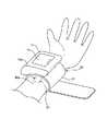
図1は、この発明の血圧計を被験者の左手首90に巻き付けて装着した装着状態における血圧計の外観を斜視図により示している。 FIG. 1 is a perspective view showing an external appearance of a sphygmomanometer in a wearing state in which the sphygmomanometer of the present invention is wound around the
図1に示すように、この実施形態の血圧計は、血圧測定用カフとしてのカフ20と、このカフ20に対向して取り付けられた本体10とで構成されている。また、上記血圧計は、カフ20と反対側の本体10の外面10aに沿って配置された表示部11を有している。 As shown in FIG. 1, the sphygmomanometer according to this embodiment includes a
上記本体10は、上記外面10aに対して垂直な方向から見たとき、略長方形の形状を有する。図1では、本体10の長手方向(左右方向)がカフ20の外周面の上部と略平行になっている。 The
上記カフ20は、帯状袋21と、この帯状袋21に内包された流体袋(図3A,図3B中に符号22で示す。)とを有している。上記流体袋は、流体としての空気が供給されて膨張することで左手首90を圧迫する。上記帯状袋21は、布製で、一部に図示しない面ファスナが設けられている。上記血圧計は、左手の手のひらを上方へ向けてカフ20の本体10に沿った部分を左手首90に載せ、カフ20によって左手首90を取り巻き、上記面ファスナにより、カフ20が二重に重なった部分を固定することで装着されている。 The
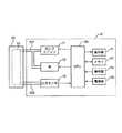
図2は、上記本体10の内部を外面10a側から見たところを模式的に示している。なお、図2には、理解の容易のためにXYZ直交座標を設けている(図3Aから図7も同様)。 FIG. 2 schematically shows the inside of the
図2に示すように、上記本体10は、本体ケーシング12と、上記流体袋に空気を供給可能なポンプユニット31と、このポンプユニット31に接続され上記流体袋内の空気を排出しまたは封入するために開閉される弁32と、基板41とを有している。 As shown in FIG. 2, the
上記ポンプユニット31は、モータ311とエアポンプ312とから構成されている。また、上記圧力センサ33は、例えばピエゾ抵抗式圧力センサからなる。The
上記基板41は、略L字形状を有し、外面10aと平行に、すなわちXY平面に沿って配置されている。上記基板41上には、上記流体袋内の圧力(以下、「カフ圧」という)を検出するための圧力センサ33が搭載されている。また、上記基板41上には、CPU(Central Processing Unit;中央演算処理装置)およびその補助回路を含み、上記血圧計を制御する制御部50が設けられている。 The
上記ポンプユニット31、弁32、および基板41は、本体ケーシング12の内側でXY面内に並んで配置されている。また、上記ポンプユニット31および弁32は、基板41の略L字形状のくぼみに配置されている。このため、上記ポンプユニット31、弁32、および基板41の設置面積を確保しつつ、これらをコンパクトに配置できて、製品の小型化および薄型化を図ることができる。 The
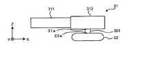
図3Aは、ポンプユニット31と流体袋22との接続を説明するために、ポンプユニット31および流体袋22の断面を模式的に示している。また、図3Bは、圧力センサ33と流体袋22との接続を説明するために、圧力センサ33および流体袋22の断面を模式的に示している。 FIG. 3A schematically shows a cross section of the
図3Aに示すように、ポンプユニット31(より詳しくは、エアポンプ312)は、このポンプユニット31に設けられた空気排出口31aが流体袋22に設けられた空気供給口22aに対向する態様で配置されている。これに応じて、ポンプユニット31は、流体袋22の空気供給口22aの真上(図3Aにおいて)に重なって配置されている。上記ポンプユニット31は、流体袋22に対して第1の流体経路301を介して接続されている。また、上記弁32は、流体袋22に対してエアポンプ312および第1の流体経路301を介して接続されている。As shown in FIG. 3A, thepump unit 31 (more specifically, the air pump 312) is arranged in such a manner that the
上記第1の流体経路301は、ポンプユニット31の空気排出口31aと流体袋22の空気供給口22aとの間でZ方向にストレートに延在し、ポンプユニット31から供給された空気を流体袋22へ送り込み、または流体袋22内の空気を弁32に送るようになっている。The first
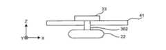
図3Bに示すように、上記圧力センサ33は、第2の流体経路302を介して流体袋22に接続されている。 As shown in FIG. 3B, the
上記第2の流体経路302は、圧力センサ33と流体袋22との間で、第1の流体経路301と同様にZ方向にストレートに延在し、流体袋22内の空気を圧力センサ33へ送るようになっている。この送られた空気により、圧力センサ33は、カフ圧を検出している。 The second
図4は、本体ケーシング12からポンプユニット31、弁32および基板41を取り外した状態の本体ケーシング12の内面を本体10の外面10aに対して垂直な方向から見たところを示している。 FIG. 4 shows a state in which the inner surface of the main body casing 12 with the
図4に示すように、上記本体ケーシング12は、本体ケーシング12の底部から内面側、すなわち+Z方向へ突出している略円筒形状の第1,第2の凸部111,112を有している。この第1の凸部111は、第1の流体経路301の一部を形成するとともに、ポンプユニット31の図示しない空気供給口に接続されるようになっている。上記第2の凸部112は、第2の流体経路302の一部を形成するとともに、圧力センサ33に接続されるようになっている。 As shown in FIG. 4, the
また、上記本体ケーシング12は、本体ケーシング12の底部から内面側、すなわち+Z方向へ突出している複数の係合リブ113を有している。これらの複数の係合リブ113は、ポンプユニット31および弁32に対応した位置に設けられ、ポンプユニット31および弁32と係合して、それらを固定するようになっている。 The
また、上記本体ケーシング12は、本体ケーシング12の側部から内面側へ突出している複数の係合リブ114を有している。これらの複数の係合リブ114は、基板41に対応した位置に設けられ、基板41と係合して固定するようになっている。 The
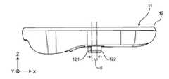
図5は、図4のA−A線に垂直な方向に見たときの本体10を示している。 FIG. 5 shows the
図5に示すように、本体ケーシング12は、本体ケーシング12の底部から外面側、すなわち−Z方向へ突出している円形管状の第1,第2のノズル121,122を有している。 As shown in FIG. 5, the
上記第1のノズル121は、第1の凸部111に対応する位置に設けられ、第1の凸部111と連通して第1の流体経路301を形成している。上記第1のノズル121は、流体袋22に取り付けられて、流体袋22への空気供給口または流体袋22からの空気排出口となる。 The
上記第2のノズル122は、第2の凸部112に対応する位置に設けられ、第2の凸部112と連通して第2の流体経路302を形成している。上記第2のノズル122は、流体袋22に取り付けられて、流体袋22からの空気取出口となる。 The
上記第1,第2のノズル121,122の中心間距離は2cmである。したがって、上記血圧計の装着状態では、上記第1のノズル121と第2のノズル122との上記左手首の周方向に関するズレd、つまり第1の流体経路301と第2の流体経路302との上記ズレdは、2cmである。 The distance between the centers of the first and
ここで、人間の手首は、大きく分けると、手のひら側に実質的に平坦な平坦部(図1中に符号90aで示す。)を有している。上記手のひら側の平坦部90aの幅は、統計データによると、99%以上の人が2cmよりも大きい。 Here, when roughly divided, the human wrist has a substantially flat portion (indicated by
このため、第1,第2のノズル121,122をともに左手首90の上記手のひら側の平坦部90aに対応する位置に配置できる。したがって、本体10の座面の形状を左手首90の形状に沿わせることができるので、本体10が取り付けられたカフ20による上記左手首に対する圧迫力の低下を防止して、血圧測定の精度が低下するのを防止できる。 For this reason, both the first and
図6は、図4のB−B線に沿って切断した本体ケーシング12の断面を示している。 FIG. 6 shows a cross section of the
図6に示すように、上記第2の凸部112の内面112aと、第2のノズル122の内面122aとは連通し、第2の流体経路302を形成している。 As shown in FIG. 6, the
また、本体ケーシング12は、−X方向側の底部に電池収納部15を有している。この電池収納部15は、本体ケーシング12の外面側に設けられ、電池カバー16によって閉じられている。 Moreover, the
図7は、図4のC−C線に沿って切断した本体ケーシング12の断面を示している。 FIG. 7 shows a cross section of the
図7に示すように、上記第1の凸部111の内面111aと、第1のノズル121の内面121aとは連通し、第1の流体経路301を形成している。また、上記第1の流体経路301の延在方向と第2の流体経路302の延在方向とは、共にZ方向で同じである。したがって、製品の小型化および薄型化を図ることができる。また、部品点数や組立て工数を削減できて、製品のコストダウンをさらに図ることができる。 As shown in FIG. 7, the
図8に示すように、上記本体10は、この本体10の基板41上に搭載された制御部50を構成するCPU(Central Processing Unit)100、表示部11、メモリ51、操作部52、電源部53を含む。 As shown in FIG. 8, the
上記表示部11は、ディスプレイおよびインジケータ等を含み、CPU100からの制御信号に従って所定の情報を表示する。具体的には、表示部11は、上記血圧計によって測定された被験者の血圧に関連する情報、例えば最高血圧である収縮期血圧(SBP(Systolic Blood Pressure))、最低血圧である拡張期血圧(DBP(Diastolic Blood Pressure))および脈拍数を表示する。 The
上記操作部52は、電源部53をONまたはOFFするための指示の入力を受付ける電源スイッチや、血圧の測定開始の指示を受け付けるための血圧測定スイッチを含む。上記電源スイッチおよび血圧測定スイッチは、操作者による指示に応じた操作信号をCPU100に入力する。 The
上記メモリ51は、上記血圧計を制御するためのプログラムのデータ、上記血圧計を制御するために用いられるデータ、上記血圧計の各種機能を設定するための設定データ、および血圧値や脈拍数の測定結果のデータなどを記憶する。また、メモリ51は、プログラムが実行されるときのワークメモリなどとして用いられる。 The
上記CPU100は、メモリ51に記憶された上記血圧計を制御するためのプログラムに従って、操作部52からの操作信号に応じて、ポンプユニット31や弁32を駆動する制御を行う。また、CPU100は、圧力センサ33からの信号に基づいて、血圧値や脈拍数を算出し、表示部11およびメモリ51を制御する。 The
上記電源部53は、CPU100、ポンプユニット31、弁32、圧力センサ33、表示部11、メモリ51の各部に電力を供給する。 The power supply unit 53 supplies power to each unit of the
上記ポンプユニット31は、カフ20に内包されている流体袋22内の圧力(カフ圧)を加圧するために、第1の流体経路301を介して、流体袋22に空気を供給する。弁32は、第1の流体経路301を介して流体袋22の空気を排出し、または封入して、カフ圧を制御するために開閉される。上記圧力センサ31は、第2の流体経路302を介して、流体袋22に接続されている。圧力センサ31からの信号は、CPU100に出力される。 The
上述のように、上記血圧計では、第1の流体経路301は、ポンプユニット31と流体袋22との間でストレートに延在している。このとき、エアポンプ312の空気排出口と、流体袋22への空気供給口とが同じ方向を向いているので、屈曲したエア配管やエア通路を設けることなくストレートのエア配管のみで簡単に構成できる。したがって、製品の小型化および薄型化を図ることができる。また、部品点数や組立て工数を削減できて、製品のコストダウンを図ることができる。 As described above, in the sphygmomanometer, the first
また、上記第2の流体経路302は、流体袋22と圧力センサ33との間でストレートに延在している。このため、屈曲したエア配管やエア通路を設けることなくストレートのエア配管のみで簡単に構成できる。したがって、製品の小型化および薄型化を図ることができる。また、部品点数や組立て工数を削減できて、製品のコストダウンを図ることができる。また、流体袋22と圧力センサ33とを簡単に接続できて、血圧計を簡単に組み立てられる。 The second
なお、上記血圧計を左手首に装着するとしたが、右手首や足首、指など人体のどこに装着してもよい。 Although the sphygmomanometer is attached to the left wrist, it may be attached anywhere on the human body, such as the right wrist, ankle, or finger.
また、上記実施形態では、第2の流体経路302は、圧力センサ33と流体袋22との間で、Z方向にストレートに延在していたが、圧力センサ33と流体袋22との間で屈曲していてもよい。 In the above embodiment, the second
また、上記実施形態では、上記第1の流体経路301の延在方向と第2の流体経路302の延在方向とは、共にZ方向で同じであったが、これに限られるものではない。上記第1の流体経路の延在方向と第2の流体経路の延在方向とが異なるようにしてもよい。 Moreover, in the said embodiment, although the extension direction of the said 1st fluid path |
また、上記実施形態では、第1の流体経路301と第2の流体経路302とのズレdは、2cmであったが、これに限られるものではない。第1の流体経路と第2の流体経路との上記ズレは、例えば1cm,0.5cm,0.1cmなど、2cm以下であれば、どのような大きさにしてもよい。 In the above embodiment, the shift d between the first
また、上記実施形態では、圧力センサ33および制御部50が基板41上に搭載されていたが、例えば本体ケーシングの側部や底部など、どこに配置してもよい。 Moreover, in the said embodiment, although the
また、上記実施形態では、ポンプユニット31、弁32、および基板41は、本体ケーシング12の内側でXY面内に並んで配置されていたが、例えば、ポンプユニットおよび弁と、基板41とが異なる面内に配置されていてもよい。 Moreover, in the said embodiment, although the
また、上記実施形態では、基板41は、略L字形状であったが、例えば略長方形状や略T字形状など、どのような形状にしてもよい。 Moreover, in the said embodiment, although the board |
また、上記実施形態では、ポンプユニット31は、モータ311とエアポンプ312から構成されていたが、例えば圧電ポンプやソレノイドポンプなど、別のポンプで構成してもよい。 Moreover, in the said embodiment, although the
また、上記実施形態では、流体袋22に空気を供給していたが、例えば水など、どのような流体を供給してもよい。 Moreover, in the said embodiment, although air was supplied to the
10 本体
11 表示部
20 カフ
22 流体袋
31 ポンプユニット
32 弁
33 圧力センサ
41 基板
50 制御部
301 第1の流体経路
302 第2の流体経路DESCRIPTION OF
Claims (6)
Translated fromJapanese上記血圧測定用カフに対向して取り付けられた本体と、
上記本体の内部に配置され、上記流体袋に流体を供給可能なポンプと、
上記ポンプから上記流体袋へ流体を送り込み又は上記流体袋から流体を排出させる第1の流体経路と
を備え、
上記ポンプは、このポンプに設けられた流体排出口が上記流体袋に設けられた流体供給口に対向する態様で配置され、
上記第1の流体経路は、上記ポンプの上記流体排出口と上記流体袋の上記流体供給口との間でストレートに延在していることを特徴とする血圧計。A blood pressure measurement cuff containing a fluid bag to which fluid is supplied;
A body attached opposite the blood pressure measurement cuff;
A pump disposed inside the main body and capable of supplying fluid to the fluid bag;
A first fluid path for sending fluid from the pump to the fluid bag or discharging fluid from the fluid bag;
The pump is arranged in such a manner that a fluid discharge port provided in the pump faces a fluid supply port provided in the fluid bag,
The sphygmomanometer, wherein the first fluid path extends straight between thefluid discharge port of the pump and thefluid supply port of the fluid bag.
上記本体の内部に配置され、上記流体袋内の圧力を検知可能な圧力センサと、
上記流体袋から上記圧力センサへ流体を送り込む第2の流体経路と
を備え、
上記第2の流体経路は、上記流体袋と上記圧力センサとの間でストレートに延在していることを特徴とする血圧計。The sphygmomanometer according to claim 1,
A pressure sensor disposed inside the main body and capable of detecting the pressure in the fluid bag;
A second fluid path for feeding fluid from the fluid bag to the pressure sensor,
The sphygmomanometer, wherein the second fluid path extends straight between the fluid bag and the pressure sensor.
上記第1の流体経路の延在方向と上記第2の流体経路の延在方向とは、同じであることを特徴とする血圧計。The sphygmomanometer according to claim 2,
The sphygmomanometer, wherein the extending direction of the first fluid path and the extending direction of the second fluid path are the same.
上記血圧測定用カフを被験者の手首に巻き付けた装着状態において、
上記手首の周方向に関して、上記第1の流体経路と上記第2の流体経路とのズレが2cm以下であることを特徴とする血圧計。The sphygmomanometer according to claim 3,
In a wearing state in which the blood pressure measurement cuff is wrapped around the wrist of the subject,
A sphygmomanometer, wherein a displacement between the first fluid path and the second fluid path is 2 cm or less with respect to a circumferential direction of the wrist.
上記本体の内部に配置され、上記血圧計を制御する制御部を搭載した基板を備え、
上記基板と上記ポンプとは、上記第1の流体経路の延在方向に対して垂直な方向に並んで配置されていることを特徴とする血圧計。The sphygmomanometer according to any one of claims 1 to 4,
It is arranged inside the main body, and includes a board on which a control unit for controlling the blood pressure monitor is mounted,
The sphygmomanometer, wherein the substrate and the pump are arranged side by side in a direction perpendicular to an extending direction of the first fluid path.
上記基板は、略L字形状を有し、
上記ポンプは、上記略L字形状のくぼみに配置されていることを特徴とする血圧計。The sphygmomanometer according to claim 5,
The substrate has a substantially L shape,
The sphygmomanometer, wherein the pump is disposed in the substantially L-shaped depression.
Priority Applications (5)
| Application Number | Priority Date | Filing Date | Title |
|---|---|---|---|
| JP2012093078AJP5939008B2 (en) | 2012-04-16 | 2012-04-16 | Sphygmomanometer |
| DE112013002058.0TDE112013002058T5 (en) | 2012-04-16 | 2013-04-03 | Blood Pressure Monitor |
| PCT/JP2013/060228WO2013157392A1 (en) | 2012-04-16 | 2013-04-03 | Blood pressure meter |
| CN201380015642.2ACN104168822B (en) | 2012-04-16 | 2013-04-03 | Sphygomanometer |
| US14/509,786US10349843B2 (en) | 2012-04-16 | 2014-10-08 | Blood pressure meter |
Applications Claiming Priority (1)
| Application Number | Priority Date | Filing Date | Title |
|---|---|---|---|
| JP2012093078AJP5939008B2 (en) | 2012-04-16 | 2012-04-16 | Sphygmomanometer |
Publications (2)
| Publication Number | Publication Date |
|---|---|
| JP2013220187A JP2013220187A (en) | 2013-10-28 |
| JP5939008B2true JP5939008B2 (en) | 2016-06-22 |
Family
ID=49383357
Family Applications (1)
| Application Number | Title | Priority Date | Filing Date |
|---|---|---|---|
| JP2012093078AActiveJP5939008B2 (en) | 2012-04-16 | 2012-04-16 | Sphygmomanometer |
Country Status (5)
| Country | Link |
|---|---|
| US (1) | US10349843B2 (en) |
| JP (1) | JP5939008B2 (en) |
| CN (1) | CN104168822B (en) |
| DE (1) | DE112013002058T5 (en) |
| WO (1) | WO2013157392A1 (en) |
Families Citing this family (25)
| Publication number | Priority date | Publication date | Assignee | Title |
|---|---|---|---|---|
| JP5939008B2 (en)* | 2012-04-16 | 2016-06-22 | オムロンヘルスケア株式会社 | Sphygmomanometer |
| JP6103131B2 (en) | 2014-08-11 | 2017-03-29 | 株式会社村田製作所 | Fluid control device |
| TWM512388U (en)* | 2015-08-19 | 2015-11-21 | Syncmold Entpr Corp | Blood pressure monitor |
| US10379742B2 (en)* | 2015-12-28 | 2019-08-13 | Netapp, Inc. | Storage zone set membership |
| JP6172351B1 (en) | 2016-07-05 | 2017-08-02 | オムロンヘルスケア株式会社 | Sphygmomanometer |
| JP6849488B2 (en) | 2017-03-07 | 2021-03-24 | オムロン株式会社 | Sphygmomanometer, blood pressure measurement method and equipment |
| JP6905944B2 (en)* | 2018-01-12 | 2021-07-21 | オムロン株式会社 | Blood pressure measuring device |
| JP6938391B2 (en) | 2018-01-15 | 2021-09-22 | オムロン株式会社 | Blood pressure measuring device |
| JP6876636B2 (en) | 2018-01-15 | 2021-05-26 | オムロン株式会社 | Blood pressure measuring device |
| JP7027174B2 (en) | 2018-01-15 | 2022-03-01 | オムロン株式会社 | Blood pressure measuring device |
| JP7019425B2 (en) | 2018-01-15 | 2022-02-15 | オムロン株式会社 | Manufacturing method of blood pressure measuring device and blood pressure measuring device |
| JP7094875B2 (en)* | 2018-12-27 | 2022-07-04 | オムロンヘルスケア株式会社 | Blood pressure measuring device |
| CA3134842A1 (en) | 2019-04-17 | 2020-10-22 | Masimo Corporation | Patient monitoring systems, devices, and methods |
| CN112237419B (en)* | 2019-07-19 | 2023-07-14 | 欧姆龙健康医疗事业株式会社 | Sphygmomanometer |
| USD921202S1 (en) | 2019-08-16 | 2021-06-01 | Masimo Corporation | Holder for a blood pressure device |
| USD919100S1 (en) | 2019-08-16 | 2021-05-11 | Masimo Corporation | Holder for a patient monitor |
| USD985498S1 (en) | 2019-08-16 | 2023-05-09 | Masimo Corporation | Connector |
| USD917704S1 (en) | 2019-08-16 | 2021-04-27 | Masimo Corporation | Patient monitor |
| USD919094S1 (en) | 2019-08-16 | 2021-05-11 | Masimo Corporation | Blood pressure device |
| USD927699S1 (en) | 2019-10-18 | 2021-08-10 | Masimo Corporation | Electrode pad |
| CN112971751B (en)* | 2019-12-12 | 2025-02-21 | 华为技术有限公司 | Electronic devices for measuring blood pressure |
| CN113142758B (en)* | 2020-01-23 | 2025-04-08 | 华为技术有限公司 | Wearable devices |
| USD933232S1 (en) | 2020-05-11 | 2021-10-12 | Masimo Corporation | Blood pressure monitor |
| USD979516S1 (en) | 2020-05-11 | 2023-02-28 | Masimo Corporation | Connector |
| CN113017587B (en)* | 2021-03-08 | 2024-09-20 | 自贡市第一人民医院 | High-precision wrist sphygmomanometer |
Family Cites Families (15)
| Publication number | Priority date | Publication date | Assignee | Title |
|---|---|---|---|---|
| US4469107A (en)* | 1979-01-02 | 1984-09-04 | Asmar Raymond A | Automatic blood pressure measurement device with threshold compensation circuitry and method for performing the same |
| JPS59232531A (en)* | 1983-06-15 | 1984-12-27 | 松下電工株式会社 | Hemomanometer |
| JPH0757219B2 (en)* | 1986-06-25 | 1995-06-21 | 松下電工株式会社 | Sphygmomanometer |
| JP3175980B2 (en)* | 1992-10-02 | 2001-06-11 | 松下電工株式会社 | Sphygmomanometer |
| JP3531302B2 (en)* | 1995-08-01 | 2004-05-31 | 松下電工株式会社 | Sphygmomanometer |
| US6251080B1 (en)* | 1999-05-13 | 2001-06-26 | Del Mar Medical Systems, Llc | Self contained ambulatory blood pressure cincture |
| DE19963623A1 (en)* | 1999-12-29 | 2001-07-12 | Braun Gmbh | Blood pressure measuring device and method for producing a component carrier of a blood pressure measuring device |
| US6685423B1 (en)* | 2000-09-25 | 2004-02-03 | Starcon International, Inc. | Method and apparatus for extracting and installing heat exchanger bundles |
| CN2446956Y (en)* | 2000-10-19 | 2001-09-12 | 汤国强 | Time and blood pressure dual-use meter |
| CN2559313Y (en)* | 2002-08-13 | 2003-07-09 | 许瑞琛 | wristband blood pressure monitor |
| CN2887249Y (en)* | 2006-01-28 | 2007-04-11 | 合世生医科技股份有限公司 | There is a device for stabilizing pressure release in the pressurization device of the sphygmomanometer |
| US20090318818A1 (en)* | 2008-06-20 | 2009-12-24 | Welch Allyn, Inc. | Blood pressure monitoring system |
| JP2010088513A (en) | 2008-10-03 | 2010-04-22 | Nippon Seimitsu Sokki Kk | Apparatus with built-in air circuit component |
| CN201767961U (en)* | 2010-08-16 | 2011-03-23 | 童文娟 | Wrist band sphygmomanometer |
| JP5939008B2 (en)* | 2012-04-16 | 2016-06-22 | オムロンヘルスケア株式会社 | Sphygmomanometer |
- 2012
- 2012-04-16JPJP2012093078Apatent/JP5939008B2/enactiveActive
- 2013
- 2013-04-03DEDE112013002058.0Tpatent/DE112013002058T5/enactivePending
- 2013-04-03WOPCT/JP2013/060228patent/WO2013157392A1/enactiveApplication Filing
- 2013-04-03CNCN201380015642.2Apatent/CN104168822B/enactiveActive
- 2014
- 2014-10-08USUS14/509,786patent/US10349843B2/enactiveActive
Also Published As
| Publication number | Publication date |
|---|---|
| US20150025400A1 (en) | 2015-01-22 |
| US10349843B2 (en) | 2019-07-16 |
| JP2013220187A (en) | 2013-10-28 |
| WO2013157392A1 (en) | 2013-10-24 |
| CN104168822A (en) | 2014-11-26 |
| DE112013002058T5 (en) | 2015-02-26 |
| CN104168822B (en) | 2016-08-31 |
Similar Documents
| Publication | Publication Date | Title |
|---|---|---|
| JP5939008B2 (en) | Sphygmomanometer | |
| JP6849488B2 (en) | Sphygmomanometer, blood pressure measurement method and equipment | |
| US11918327B2 (en) | Sphygmomanometer, blood pressure measurement method, and device | |
| CN108463161B (en) | cuff for blood pressure monitor, method for manufacturing same, and blood pressure monitor | |
| WO2017203957A1 (en) | Blood pressure measurement cuff and sphygmomanometer | |
| US20200323446A1 (en) | Blood pressure measurement device | |
| US20120253210A1 (en) | Cuff of Sphygmomanometer | |
| US20210307630A1 (en) | Blood pressure measurement device | |
| JP2017209434A (en) | Sensor assembly | |
| CN109310350A (en) | Sphygmomanometer | |
| JP2014018357A (en) | Bio-information measuring apparatus | |
| US12064222B2 (en) | Blood pressure measurement device | |
| US20240041337A1 (en) | Blood pressure measurement device | |
| US12257036B2 (en) | Blood pressure measurement device | |
| CN112367911B (en) | Blood pressure measuring device and cuff unit | |
| CN219289445U (en) | Pressure sensor for dynamic blood pressure watch | |
| US12178607B2 (en) | Blood pressure measurement device | |
| US12133718B2 (en) | Blood pressure measurement device | |
| US11969237B2 (en) | Blood pressure measurement device | |
| JP5141650B2 (en) | Sphygmomanometer | |
| JP2021003514A (en) | Sphygmomanometer | |
| US12138023B2 (en) | Blood pressure measurement device | |
| US12440113B2 (en) | Blood pressure measurement device | |
| US20250185927A1 (en) | Cuff structure and blood pressure measurement device | |
| JP2009219540A (en) | Hemodynamometer |
Legal Events
| Date | Code | Title | Description |
|---|---|---|---|
| A621 | Written request for application examination | Free format text:JAPANESE INTERMEDIATE CODE: A621 Effective date:20150310 | |
| A131 | Notification of reasons for refusal | Free format text:JAPANESE INTERMEDIATE CODE: A131 Effective date:20160202 | |
| A521 | Written amendment | Free format text:JAPANESE INTERMEDIATE CODE: A523 Effective date:20160323 | |
| TRDD | Decision of grant or rejection written | ||
| A01 | Written decision to grant a patent or to grant a registration (utility model) | Free format text:JAPANESE INTERMEDIATE CODE: A01 Effective date:20160419 | |
| A61 | First payment of annual fees (during grant procedure) | Free format text:JAPANESE INTERMEDIATE CODE: A61 Effective date:20160502 | |
| R150 | Certificate of patent or registration of utility model | Ref document number:5939008 Country of ref document:JP Free format text:JAPANESE INTERMEDIATE CODE: R150 |