JP5938890B2 - Image forming apparatus, pattern position detecting method, and image forming system - Google Patents
Image forming apparatus, pattern position detecting method, and image forming systemDownload PDFInfo
- Publication number
- JP5938890B2 JP5938890B2JP2011276399AJP2011276399AJP5938890B2JP 5938890 B2JP5938890 B2JP 5938890B2JP 2011276399 AJP2011276399 AJP 2011276399AJP 2011276399 AJP2011276399 AJP 2011276399AJP 5938890 B2JP5938890 B2JP 5938890B2
- Authority
- JP
- Japan
- Prior art keywords
- light
- image forming
- recording medium
- data
- test pattern
- Prior art date
- Legal status (The legal status is an assumption and is not a legal conclusion. Google has not performed a legal analysis and makes no representation as to the accuracy of the status listed.)
- Expired - Fee Related
Links
Images


Classifications
- B—PERFORMING OPERATIONS; TRANSPORTING
- B41—PRINTING; LINING MACHINES; TYPEWRITERS; STAMPS
- B41J—TYPEWRITERS; SELECTIVE PRINTING MECHANISMS, i.e. MECHANISMS PRINTING OTHERWISE THAN FROM A FORME; CORRECTION OF TYPOGRAPHICAL ERRORS
- B41J29/00—Details of, or accessories for, typewriters or selective printing mechanisms not otherwise provided for
- B41J29/38—Drives, motors, controls or automatic cut-off devices for the entire printing mechanism
Landscapes
- Ink Jet (AREA)
- Character Spaces And Line Spaces In Printers (AREA)
Description
Translated fromJapanese本発明は、液体吐出方式の画像形成装置に関し、特に、液滴の着弾位置ずれを補正可能な画像形成装置に関する。 The present invention relates to a liquid ejection type image forming apparatus, and more particularly to an image forming apparatus capable of correcting a landing position deviation of a droplet.
液滴を用紙などのシート材に吐出して画像を形成する画像形成装置が知られている(以下、液体吐出方式の画像形成装置という)。液体吐出方式の画像形成装置は、大きくシリアル方式とラインヘッド方式のものに区分できる。シリアル方式の画像形成装置は、紙送りを繰り返しながら、紙送り方向と直角に(主走査方向に)記録ヘッドが往復移動して用紙全体に画像を形成する。ラインヘッド方式の画像形成装置は、最大用紙幅とほぼ同じ長さにノズルが並んでおり、ラインヘッド内のノズルは紙が送られ液滴を吐出するタイミングになると液滴を吐出することで画像を形成する。 There is known an image forming apparatus that forms an image by discharging droplets onto a sheet material such as paper (hereinafter, referred to as a liquid discharge type image forming apparatus). Liquid discharge type image forming apparatuses can be roughly classified into serial type and line head type. In the serial image forming apparatus, the recording head reciprocates at right angles to the paper feeding direction (in the main scanning direction) while repeating paper feeding to form an image on the entire paper. In the line head type image forming apparatus, the nozzles are arranged to be approximately the same length as the maximum paper width, and the nozzles in the line head discharge the liquid droplets when the paper is sent and the liquid droplets are discharged. Form.
しかしながら、シリアル方式の画像形成装置では、往路及び復路の双方向で1本の罫線を印刷したような場合、往路と復路で罫線の位置ずれが発生しやすいということが知られている。また、ラインヘッド方式の画像形成装置では、ノズルの加工精度や取り付け誤差などに起因して、定常的に着弾位置がずれるノズルがあると紙送り方向に平行な線が現れやすいことが知られている。 However, it is known that in a serial type image forming apparatus, when one ruled line is printed in both directions of the forward path and the backward path, positional deviation of the ruled line is likely to occur in the forward path and the backward path. Also, in line head type image forming apparatuses, it is known that a line parallel to the paper feed direction is likely to appear if there is a nozzle whose landing position steadily shifts due to nozzle processing accuracy or mounting errors. Yes.
このため、液体吐出方式の画像形成装置では、液滴の着弾位置を調整するための自動調整用のテストパターンをシート材に印刷し、テストパターンを光学的に読み取り、その読み取り結果に基づいて吐出タイミングの調整を行うことが行われることが多い(例えば、特許文献1参照。)。 For this reason, in a liquid discharge type image forming apparatus, a test pattern for automatic adjustment for adjusting the landing position of a droplet is printed on a sheet material, the test pattern is optically read, and discharge is performed based on the read result. In many cases, timing adjustment is performed (for example, refer to Patent Document 1).
特許文献1には、撥水性を有する撥水性部材上に、独立した複数の液滴で構成される基準パターンと、この基準パターンとは異なる吐出条件で吐出された独立した複数の液滴で構成される被測定パターンとを、記録ヘッドの走査方向に並べて形成させるパターン形成手段と、各パターンに光を照射する発光手段及び各パターンからの正反射光を受光する受光手段で構成される読取り手段と、この読取り手段の読取り結果に基づいて各パターン間の距離を測定して、この測定結果に基づいて記録ヘッドの液滴吐出タイミングを補正する補正手段とを備えている画像形成装置が開示されている。 In
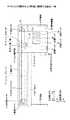
図1は、特許文献1に開示された各パターン間の距離の測定方法の一例を示す図である。特許文献1では、センサ出力電圧Soが下限閾値Vrdを切る(以下になる)点を点P2として記憶し、次に、点P2より矢示Q2方向に探索して、センサ出力電圧Soが上限閾値Vruを超える点を点P1として記憶する。そして、点P1と点P2の間の出力電圧Soより回帰直線L1を算出し、求めた回帰直線式を用いて、回帰直線L1と上下閾値の中間値Vcとの交点を算出し交点C1とする。交点C1はパターンのエッジ付近の位置を示すので、画像形成装置はパターン間の距離を求めることができる。 FIG. 1 is a diagram illustrating an example of a method for measuring a distance between patterns disclosed in
しかしながら、特許文献1に開示された液滴吐出タイミングの補正方法では、上限閾値と下限閾値の決定方法が開示されていないという問題がある。各パターンにおいて同じ上限閾値と下限閾値を用いて交点C1を求めれば、交点C1の求め方は安定するが、交点C1がパターンと撥水性部材の素地とのエッジであるとは限らない。 However, the droplet ejection timing correction method disclosed in
本発明は、上記課題に鑑み、液滴の吐出タイミングを調整する画像形成装置であって、パターンのエッジ位置をより精度よく特定できる画像形成装置を提供することを目的とする。 SUMMARY An advantage of some aspects of the invention is that it provides an image forming apparatus that adjusts the discharge timing of droplets and that can specify the edge position of a pattern with higher accuracy.
上記課題に鑑み、本発明は、記録媒体に液滴を吐出して形成された1本以上のラインを含むテストパターンを読み取って、液滴の吐出タイミングを調整する画像形成装置であって、
テストパターンのパターンデータを取得して前記記録媒体にテストパターンを形成する画像形成手段と、前記記録媒体に光を照射する発光手段及び前記記録媒体からの反射光を受光する受光手段とを有する読み取り手段と、前記記録媒体又は前記読み取り手段を等速で移動させる相対移動手段と、テストパターン上を前記光が移動している間、前記受光手段が前記光の走査位置から受光した前記反射光の強度データを取得する強度データ取得手段と、前記強度データの着目値の上下方向にそれぞれ所定数のデータを抽出し、上側及び下側のデータの回帰曲線の切片の差が最も小さくなる前記着目値を変曲点に決定する変曲点算出手段と、前記変曲点を前記ラインの位置に決定する位置検出手段と、を有することを特徴とする。In view of the above problems, the present invention is an image forming apparatus that reads a test patternincluding one or more lines formed by discharging droplets onto a recording medium and adjusts the discharge timing of the droplets.
Reading having image forming means for acquiring pattern data of a test pattern and forming a test pattern on therecording medium, light emitting means for irradiating the recording medium with light, and light receiving means for receiving reflected light from the recording medium Means , a relative moving means for moving the recording medium or the reading means at a constant speed, and the reflected light received by the light receiving means from the light scanning position while the light is moving on the test pattern. Intensity data acquisition means for acquiring intensity data, and apredetermined number of data are extracted in the vertical direction of the targetvalue of the intensity data, and the targetvalue that minimizes the difference between the intercepts of the regression curves of the upper and lower data the toand inflection point calculation means for determining the inflection point,said position detecting meansthat determine the inflection point to the position of said line, characterized in that it has a.
液滴の吐出タイミングを調整する画像形成装置であって、パターンのエッジ位置をより精度よく特定できる画像形成装置を提供することができる。 It is possible to provide an image forming apparatus that adjusts the discharge timing of liquid droplets and that can specify the edge position of a pattern with higher accuracy.
以下、本発明を実施するための形態について図面を参照しながら説明する。 Hereinafter, embodiments for carrying out the present invention will be described with reference to the drawings.
図2は、本実施形態のエッジ位置の特定の概略を説明する図の一例である。スポット光はテストパターンを構成する複数のライン(図では1本)を一定速度(等速)で横切るように移動する(以下、テストパターンとテストパターンを構成するラインを厳密には区別せずに説明する。)。用紙などのシート材は紙送りによりラインの長手方向に移動しているため、スポット光はラインを斜めに横切るように移動するが、シート材が停止してもエッジ位置の特定方法は同じである。一般的な波長のスポット光とシート材ではテストパターンの重複面積が大きいほど、スポット光の反射光が低下するとしてよい。FIG. 2 is an example of a diagram illustrating a specific outline of the edge position according to the present embodiment. The spot light moves across a plurality of lines (one line in the figure) constituting the test pattern at a constant speed (constant speed) (hereinafter, the test pattern and the lines constituting the test pattern are not strictly distinguished). explain.). Since the sheet material such as paper is moved in the longitudinal direction of the line by paper feeding, the spot light moves diagonally across the line, but the edge position specifying method is the same even if the sheet material stops. . In the spot light of a general wavelength and the sheet material, the reflected light of the spot light may decrease as the overlapping area of the test pattern increases.
図2(a)の数字I〜Vは時刻の経過を表す。
時刻I:スポット光とテストパターンは重複していない。
時刻II:スポット光の半分がテストパターンと重畳している。この瞬間、反射光の減少率が最も大きくなる(重畳している面積が単位時間に最も大きく正に変化する)。
時刻III:スポット光の全体がテストパターンと重畳している。この瞬間、反射光の強度が最も小さくなる。
時刻IV:スポット光の半分がテストパターンと重畳している。この瞬間、反射光の増加率が最も大きくなる(重畳している面積が単位時間に最も大きく負に変化する)。Numbers I to V in FIG. 2A represent the passage of time.
Time I: Spot light and test pattern do not overlap.
Time II: Half of the spot light is superimposed on the test pattern. At this moment, the reduction rate of the reflected light becomes the largest (the overlapped area changes most positively in unit time).
Time III: The entire spot light is superimposed on the test pattern. At this moment, the intensity of the reflected light becomes the smallest.
Time IV: Half of the spot light is superimposed on the test pattern. At this moment, the increase rate of the reflected light becomes the largest (the overlapping area changes most negatively per unit time).
スポット光の重心がテストパターンのラインのエッジ位置と一致するのは、時刻II及びIVである。したがって、スポット光とラインとが時刻II及びIVの関係にあることを反射光から検出できれば、エッジ位置を精度よく特定できる。 It is time II and IV that the center of gravity of the spot light coincides with the edge position of the line of the test pattern. Therefore, if it can be detected from the reflected light that the spot light and the line have the relationship between the times II and IV, the edge position can be specified with high accuracy.
このため、本実施形態では、受光素子が検出した反射光の検出電圧の変曲点に着目する。図2(b)のうち、例えば吸収面積(スポット光とテストパターンの重畳面積)によれば時刻II及びIVにおいて傾きの絶対値が最大になっている。また、図2(b)のうち、吸収面積の微分値によれば、時刻IIにおいて増加率が増加傾向から減少傾向に変化し、時刻IVにおいて増加率が減少傾向から増加傾向に変化している。このように、平面上の曲線において曲がる方向が変わる点(曲線上で曲率の符号(プラス・マイナス)が変化する点)は、変曲点である。以上から、変曲点がテストパターンのエッジ位置に一致することがわかる。本実施形態では、この変曲点に着目してエッジ位置も特定することで、液滴の着弾位置ずれを精度よく補正する。 For this reason, in this embodiment, attention is paid to the inflection point of the detection voltage of the reflected light detected by the light receiving element. In FIG. 2B, for example, according to the absorption area (the overlapping area of the spot light and the test pattern), the absolute value of the slope is maximized at times II and IV. Also, in FIG. 2B, according to the differential value of the absorption area, the increase rate changes from an increasing trend to a decreasing trend at time II, and the increasing rate changes from a decreasing trend to an increasing trend at time IV. . As described above, the point at which the bending direction changes in the curved line on the plane (the point where the sign of the curvature (plus / minus) changes on the curved line) is an inflection point. From the above, it can be seen that the inflection point coincides with the edge position of the test pattern. In the present embodiment, by focusing on the inflection point and specifying the edge position, the landing position deviation of the droplet is accurately corrected.
〔構成〕
図3は、シリアル方式の画像形成装置100の概略斜視図の一例を示す。画像形成装置100は、本体フレーム70により支持されている。画像形成装置100の長手方向にはガイドロッド1及び幅ガイド2が掛け渡され、ガイドロッド1及び副ガイド2にキャリッジ5が矢印A方向(主走査方向)に往復移動可能なように保持されている。〔Constitution〕
FIG. 3 shows an example of a schematic perspective view of the serial type
また、主走査方向には無端ベルト状のタイミングベルト9が、駆動プーリ7と加圧コロ15に張架されており、タイミングベルト9の一部がキャリッジ5に固定されている。また、駆動プーリ7は主走査モータ8により回転駆動され、これによりタイミングベルト9が主走査方向に移動し、連動してキャリッジ5も往復移動する。タイミングベルト9には加圧コロ15によって張力が掛けられており、タイミングベルト9はたるむことなくキャリッジ5を駆動させることができる。 In the main scanning direction, an endless belt-like timing belt 9 is stretched around a driving pulley 7 and a
また画像形成装置100は、インクを供給するカートリッジ60と記録ヘッドを維持・クリーニングする維持機構26を有する。 The
シート材150はキャリッジ5の下側にあるプラテン40上を、不図示のローラにより矢印B方向(副走査方向)に間欠的に搬送される。シート材50は、紙などの普通紙、光沢紙、フィルム、電子基板など液滴が付着可能な記録媒体であればよい。シート材150の搬送位置毎に、キャリッジ5は主走査方向に移動し、キャリッジ5が搭載している記録ヘッドが液滴を吐出する。吐出が終わるとシート材150が再度、搬送され、キャリッジ5が主走査方向に移動して液滴を吐出する。これを繰り返すとシート材150の全面に画像が形成される。キャリッジ5、キャリッジ5に搭載された記録ヘッド21〜24は画像形成手段の一例である。 The
図4は、キャリッジ5の動作をより詳細に説明する図の一例である。上記のガイドロッド1及び副ガイド2は左側板3と右側板4の間に掛け渡され、キャリッジ5は軸受け12と副ガイド受け部11によりガイドロッド1及び副ガイド2を摺動自在に保持され、矢印X1,X2方向(主走査方向)に移動可能となっている。 FIG. 4 is an example of a diagram for explaining the operation of the
キャリッジ5には黒(K)の液滴を吐出する記録ヘッド21,22、シアン(C)、マゼンタ(M)、イエロー(Y)の各色のインク滴を吐出する記録ヘッド23,24,が搭載されている。記録ヘッド21は黒がよく使用されるために配置したものであり、省略することもできる。 The
なお、記録ヘッド21〜24としては、インク流路内(圧力発生室)のインクを加圧する圧力発生手段(アクチュエータ手段)として圧電素子を用いてインク流路の壁面を形成する振動板を変形させてインク流路内容積を変化させてインク滴を吐出させるいわゆるピエゾ型のもの、発熱抵抗体を用いてインク流路内でインクを加熱して気泡を発生させることによる圧力でインク滴を吐出させるいわゆるサーマル型のもの、又は、インク流路の壁面を形成する振動板と電極とを対向配置し、振動板と電極との間に発生させる静電力によって振動板を変形させることで、インク流路内容積を変化させてインク滴を吐出させる静電型のもの、などを用いることができる。 As the recording heads 21 to 24, a piezoelectric element is used as a pressure generating means (actuator means) for pressurizing ink in the ink flow path (pressure generating chamber), and a diaphragm that forms the wall surface of the ink flow path is deformed. The so-called piezo type that discharges ink drops by changing the volume in the ink flow path, and discharges ink drops with pressure by heating the ink in the ink flow path using a heating resistor to generate bubbles A so-called thermal type or a diaphragm that forms the wall surface of the ink flow path and an electrode are arranged opposite to each other, and the diaphragm is deformed by an electrostatic force generated between the vibration plate and the electrode, whereby the ink flow path An electrostatic type that discharges ink droplets by changing the internal volume can be used.
キャリッジ5を移動走査する主走査機構32は、主走査方向の一方側に配置される主走査モータ8と、主走査モータ8によって回転駆動される駆動プーリ7と、主走査方向の他方側に配置された加圧コロ15と、駆動プーリ7と加圧コロ15との間に掛け回されたタイミングベルト9とを備えている。なお、加圧コロ15は、図示しないテンションスプリングによって外方(駆動プーリ7に対して離れる方向)にテンションが作用させられている。 The
タイミングベルト9は、キャリッジ5の背面側に設けたベルト保持部10に一部分が固定保持されていることで、タイミングベルト9の無端移動に伴い主走査方向にキャリッジ5を牽引する。 A part of the timing belt 9 is fixedly held by a
また、キャリッジ5の主走査方向に沿うようにエンコーダシート41が配置されており、キャリッジ5に設けたエンコーダセンサ42によって当該エンコーダシート42のスリットを読取ることで、キャリッジ5の主走査方向の位置を検知することができる。このキャリッジ5が主走査領域のうち記録領域に存在する場合、シート材150が図示しない紙送り機構によってキャリッジ5の主走査方向と直交する矢示Y1,Y2方向(副走査方向)に間欠的に搬送される。 Further, an encoder sheet 41 is arranged along the main scanning direction of the
以上説明した、本実施形態に係る画像形成装置100では、キャリッジ5を主走査方向に移動し、シート材150を間欠的に送りながら、記録ヘッド21〜24を画像情報に応じて駆動して液滴を吐出させることによってシート材150に所要の画像を形成することができる。 In the
キャリッジ5の一側面には、着弾位置のずれを検出(テストパターンの読取り)するための印字位置ずれセンサ30が搭載されている。印字位置ずれセンサ30は、LEDなどの発光素子及び反射型フォトセンサで構成した受光素子によって、シート材150に形成された着弾位置検出用のテストパターンを読み取る。 On one side surface of the
この印字位置ずれセンサ30は記録ヘッド21用のものなので、記録ヘッド22〜24の液滴吐出タイミングを調整するため記録ヘッド22〜24と並列に別の印字位置ずれセンサ30を搭載することが好ましい。また、印字位置ずれセンサ30を記録ヘッド22〜24と並列になるようにスライドさせる機構がキャリッジ5に搭載されていれば、一台の印字位置ずれセンサ30で記録ヘッド22〜24の液滴吐出タイミングを調整できる。または、画像形成装置100がシート材150を逆方向に送っても、一台の印字位置ずれセンサ30で記録ヘッド22〜24の液滴吐出タイミングを調整できる。 Since the print
図5は、画像形成装置100の制御部300のブロック図の一例である。制御部300は、外部I/F311と接続された主制御部310を有する。主制御部310は、CPU301と、ROM302、RAM303、NVRAM304、ASIC305、及び、FPGA(Field Programmable Gate Array)306を有する。CPU301はROM302に記憶されたプログラム3021を実行して、画像形成装置100の全体を制御する。ROM302にはこのプログラム3021の他、初期値や制御のためのパラメータなど固定データが格納されている。RAM303は、プログラムや画像データ等を一時的に格納する作業メモリであり、NVRAM304は、装置の電源が遮断されている間も設定条件などのデータを保持するための不揮発性メモリである。ASIC305は画像データに対する各種信号処理、並び替え等を行なったり、各種のエンジンを制御する。FPGA306は、装置全体を制御するための入出力信号を処理する。 FIG. 5 is an example of a block diagram of the control unit 300 of the
主制御部310は、この装置全体の制御を司るとともにテストパターンの形成、テストパターンの検出、着弾位置の調整(補正)などに関わる制御を司る。後述するように、本実施例では主にCPU301がROM302に記憶されたプログラム3021を実行してエッジ位置の検出を行うが、一部又は全てをFPGA306やASIC305など、LSIが行ってもよい。 The
外部I/F311は、ネットワークに接続された他の機器と通信するための通信装置、USB、IEEE1394、と接続するためのバスやブリッジであり、外部からのデータを主制御部310に送出する。また、外部I/F311は主制御部310が生成したデータを外部に出力する。外部I/F311には脱着可能な記憶媒体320が装着可能であり、プログラム3021は記憶媒体320に記憶された状態や、外部からの通信装置を介して配信される。 The external I /
また、制御部300は、ヘッド駆動制御部312、主走査駆動部313、副走査駆動部314、給紙駆動部315、排紙駆動部316、及び、スキャナ制御部317を有する。ヘッド駆動制御部312は、記録ヘッド21〜24のそれぞれの吐出有無、吐出する場合の液滴吐出タイミング及び吐出量を制御する。ヘッド駆動制御部312は、記録ヘッド21〜24を駆動制御するためのヘッドデータ生成配列変換用ASICを有し(ヘッドドライバ)、印刷データ(ディザ処理などが施されたドットデータ)に基づき、液滴の有無と液滴の大きさを示す駆動信号を生成して、記録ヘッド21〜24に供給する。記録ヘッド21〜24はノズル毎にスイッチを有しており、駆動信号に基づきオン・オフすることで、記録ヘッド21〜23は印刷データにより指定されるシート材150の位置に指定されるサイズの液滴を着弾させる。なお、ヘッド駆動制御部312のヘッドドライバは記録ヘッド21〜24側に設けられてもよいし、ヘッド駆動制御部312と記録ヘッド21〜24が一体になっていてもよい。図示する構成は一例である。 The control unit 300 includes a head
主走査駆動部(モータドライバ)313は、キャリッジ5を移動走査する主走査モータ8を駆動する(例えば主走査駆動部313は、特許請求の範囲の相対移動手段に相当する)。主制御部310には、前述したキャリッジ位置を検出するエンコーダセンサ42が接続されており、主制御部310はこの出力信号に基づいてキャリッジ5の主走査方向の位置を検出する。そして、主走査駆動部313を介して主走査モータ8を駆動制御することでキャリッジ5を主走査方向に往復移動させる。 A main scanning drive unit (motor driver) 313 drives a
副走査駆動部(モータドライバ)314は紙送りするための副走査モータ132を駆動する。主制御部310には、副走査方向の移動量を検出するロータリエンコーダセンサ131からの出力信号(パルス)が入力され、主制御部310はこの出力信号に基づいて紙送り量を検出し、副走査駆動部314を介して副走査モータ132を駆動制御することで図示しない搬送ローラを介してシート材を紙送りする。 A sub-scanning driving unit (motor driver) 314 drives a
給紙駆動部315は給紙トレイからシート材を給紙する給紙モータ133を駆動する。排紙駆動部316は、印刷されたシート材150をプラテン上に排紙するローラを駆動する排紙モータ134を駆動する。なお、排紙駆動部316は、副走査駆動部314により代用してもよい。 A
スキャナ制御部317は、画像読取部135を制御する。画像読取部135は、原稿を光学的に読み取り画像データを生成する。 The
また、主制御部310には、テンキー、プリントスタートキーなどの各種キー及び各種表示器を含む操作/表示部136が接続されている。主制御部310は、操作/表示部136を介してユーザが操作したキー入力の受け付け、メニューの表示などを行う。 The
その他図示しないが、維持機構26を駆動する維持回復モータを駆動するための回復系駆動部、各種のソレノイド(SOL)類を駆動するソレノイド類駆動部(ドライバ)、電磁クラック類などを駆動するクラッチ駆動部、を有していてもよい。また、主制御部310には、その他の図示しない各種センサの検出信号も入力されるが図示を省略している。 Although not shown in the drawings, a recovery drive unit for driving a maintenance recovery motor that drives the maintenance mechanism 26, a solenoid drive unit (driver) for driving various solenoids (SOL), a clutch for driving electromagnetic cracks, etc. You may have a drive part. In addition, detection signals from various other sensors (not shown) are also input to the
主制御部310は、シート材上にテストパターンを形成する処理を行い、形成したテストパターンに対し、キャリッジ5に搭載した印字位置ずれセンサ30の発光素子を発光させる発光駆動制御を行う。そして、受光素子の出力信号を取得しテストパターンの反射光を電気的に読取り、この読取り結果から着弾位置ずれ量を検出し、更に着弾位置ずれ量に基づいて記録ヘッド21〜24の液滴吐出タイミングを着弾位置ずれがなくなるように補正する制御を行う。 The
〔着弾位置ずれの補正〕
図6は、印字位置ずれセンサ30がテストパターンのエッジ位置を検出するための構成を模式的に示す図の一例である。図6は、図4の記録ヘッド21と印字位置ずれセンサ30を右側面板4から見た図になっている。例えば印字位置ずれセンサ30は、特許請求の範囲の読み取り手段に相当する。[Correction of landing position deviation]
FIG. 6 is an example of a diagram schematically illustrating a configuration for the print
印字位置ずれセンサ30は、主走査方向と直交する方向に並ぶ、発光素子402と受光素子403を有している。発光素子402と受光素子403の配置は逆でもよい。発光素子402は、後述するスポット光をテストパターンに投光して、受光素子403はシート材150に反射した光、プラテン40からの反射光、その他の散乱光などを受光する。発光素子402と受光素子403は筐体の内側に固定され、印字位置ずれセンサ30のプラテン40に対向する面は、レンズ405により外部から遮蔽されている。このように、印字位置ずれセンサ30はパッケージ化されており、単体で流通することができる。 The print
印字位置ずれセンサ30内において、発光素子402及び受光素子403は、キャリッジ5の走査方向に対して直交する方向に配置されている(副走査方向に並行に配置されている)。これにより、キャリッジ5の移動速度変動による検出結果への影響を低減することができる。
発光素子402には例えば、LEDを採用することができるが、可視光を投射可能な光源(例えば、レーザ、各種のランプ)であればよい。可視光とするのは、スポット光がテストパターンにより吸収されることを期待するためである。なお、発光素子402の波長は固定であるが、波長が異なる発光素子402を搭載した複数の印字位置ずれセンサ30を搭載することも可能である。In the print
For example, an LED may be used as the
また、発光素子402が形成するスポット径は、高精度のレンズを使用せずに安価なレンズを使用するためにmmオーダーとなっている。このスポット径は、テストパターンのエッジの検出精度と関係するが、mmオーダーでも本実施形態のエッジ位置の求め方であれば十分に高精度にエッジ位置を検出できる。ただし、スポット径をより小さくすることも可能である。 Further, the spot diameter formed by the
CPU301は、所定のタイミングになると着弾位置ずれ補正を開始する。このタイミングは、例えば、ユーザが操作/表示部136から着弾位置ずれ補正を指示したタイミング、CPU301がインク吐出前に発光素子402が発光しその時の反射光の強度が所定値以下であることから特定のシート材150であると判定したタイミング、最後に着弾位置ずれ補正を行った際の温度と湿度を記憶しておき温度又は湿度のいずれかが閾値以上ずれたと判定したタイミング、定期的(毎時、毎日、毎週等)なタイミング、等がある。 The
テストパターンの形成について説明する。
CPU301は主走査制御部313にキャリッジ5の往復移動と、ヘッド駆動制御部312に予め定められたテストパターンを印刷データとして液滴の吐出を指示する。主走査制御部313は、シート材150に対して、キャリッジ5を主走査方向に往復移動させるとともに、ヘッド駆動制御部312は記録ヘッド21から液滴を吐出させて、少なくとも2本以上の独立したラインを含むテストパターンを形成する。The formation of the test pattern will be described.
The
また、CPU301は、シート材150に形成したテストパターンを印字位置ずれセンサ30にて読取るための制御を行う。具体的には、CPU301によって発光制御手段511に印字位置ずれセンサ30の発光素子402を駆動するためのPWM値が設定され、この発光制御手段511の出力が平滑回路512で平滑化されて駆動回路513に与えられる。駆動回路513は発光素子402を発光駆動して、シート材150のテストパターンに対して発光素子402からスポット光が照射される。なお、発光制御手段511、平滑回路512、駆動回路513、光電変換回路521、ローパスフィルタ522、A/D変換回路523、及び、補正処理実行部526は主制御部310に搭載されている。共有メモリ525は例えばRAM303である。 Further, the
シート材上のテストパターンに発光素子402からのスポット光が照射されることで、テストパターンから反射される反射光が受光素子403に入射する。受光素子403は反射光の強度信号を光電変換回路521に出力する。具体的には、光電変換回路521は、強度信号を光電変換して、この光電変換信号をローパスフィルタ回路522に出力する。ローパスフィルタ回路522は高周波のノイズ分を除去した後、A/D変換回路523に光電変換信号を出力する。A/D変換回路523は、光電変換信号をA/D変換し、信号処理回路(FPGA)306に出力する。信号処理回路(FPGA)306は、A/D変換された検出電圧のデジタル値である検出電圧データ(検出電圧と検出電圧データは特に区別せず使用する)を共有メモリ525に格納する。例えば、検出電圧(又は検出電圧データ)は特許請求の範囲の強度データに相当する。また、光電変換信号521〜共有メモリ525は、特許請求の範囲の強度データ取得手段に相当する。 By irradiating the test pattern on the sheet material with the spot light from the
補正処理実行部526は共有メモリ525に記憶された検出電圧データを読み出し、着弾位置ずれ補正を行い、ヘッド駆動制御部312に設定する。すなわち、補正処理実行部526は、テストパターンのエッジ位置を検出して、2本のライン間の適正距離と比較することで、着弾位置ずれ量を算出する。 The correction
補正処理実行部526は着弾位置ずれがなくなるように記録ヘッド21を駆動するときの液滴吐出タイミングの補正値を算出して、この算出した液滴吐出タイミング補正値をヘッド駆動制御部312に設定する。これにより、ヘッド駆動制御部312は、記録ヘッド21を駆動する際に、補正値に基づいて液滴吐出タイミングを補正した上で記録ヘッド21を駆動するので、液滴の着弾位置ずれを低減することができる。 The correction
図7は、補正処理実行部526の機能ブロック図の一例である。補正処理実行部526は、閾値決定部601、変曲点決定部602、及び、吐出タイミング補正部603を有する。閾値決定部601は、テストパターンのエッジ位置を算出するための上限閾値Vruと下限閾値Vrdを決定する。例えば、閾値決定部601は、特許請求の範囲の閾値決定手段に相当する。変曲点決定部602は検出電圧の変曲点を決定する。例えば、変曲点決定部602は、特許請求の範囲の変曲点算出手段に相当する。吐出タイミング補正部603は、テストパターンのエッジ位置から求めた着弾位置ずれ量に基づき液滴吐出タイミングを補正する。例えば、吐出タイミング補正部603は、特許請求の範囲の位置検出手段に相当する。 FIG. 7 is an example of a functional block diagram of the correction
〔スポット光の位置とエッジ位置〕
続いて、図8、9を用いてスポット光とテストパターンのエッジ位置の関係について説明する。[Spot light position and edge position]
Next, the relationship between the spot light and the edge position of the test pattern will be described with reference to FIGS.
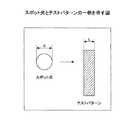
図8は、スポット光とテストパターンの一例を示す図である。スポット光はテストパターンを構成する複数のライン上(図では1本)をキャリッジ5の移動方向と同一方向に一定速度(等速)で横切るように移動する。移動する際の速度は可変でもよいが、移動中は等速である。用紙などのシート材150は紙送りによりラインの長手方向に移動しているため、スポット光はライン上をラインのエッジに対して斜めに移動するが、シート材150が停止してもエッジ位置の特定方法は同じである。一般的な波長のスポット光とシート材150ではテストパターンの重複面積が大きいほど、スポット光の反射光が低下するとしてよい。 FIG. 8 is a diagram illustrating an example of the spot light and the test pattern. The spot light moves on a plurality of lines (one in the figure) constituting the test pattern so as to cross at a constant speed (constant speed) in the same direction as the movement direction of the
なお、図8,9ではスポット径d = テストパターンのライン幅Lとするが、スポット径dとラインLの関係については後述する。 8 and 9, the spot diameter d = the line width L of the test pattern, but the relationship between the spot diameter d and the line L will be described later.
図9の数字I〜Vは時間の経過を示し、図9(a)では下のスポット光ほど時間経過が長い。図9(b)は受光素子の検出電圧の一例を、図9(c)は吸収面積(スポット光とテストパターンの重畳面積)の一例を、図9(d)は図9(c)の吸収面積を微分した吸収面積の増加率の一例を、それぞれ示す。なお、図9(d)は、図9(b)の出力波形を微分しても同等の情報が得られる。また、吸収面積は例えば検出電圧から算出されるが、絶対値である必要はないので、図9(c)の吸収面積は所定値から図9(b)の検出電圧を減算することで吸収面積と同様の波形が得られる。 Numbers I to V in FIG. 9 indicate the passage of time. In FIG. 9A, the lower the spot light, the longer the passage of time. FIG. 9B shows an example of the detection voltage of the light receiving element, FIG. 9C shows an example of the absorption area (the overlapping area of the spot light and the test pattern), and FIG. 9D shows the absorption of FIG. 9C. An example of the increase rate of the absorption area obtained by differentiating the area is shown. In FIG. 9D, equivalent information can be obtained even if the output waveform of FIG. 9B is differentiated. Moreover, although the absorption area is calculated from the detection voltage, for example, it does not have to be an absolute value. Therefore, the absorption area in FIG. 9C is obtained by subtracting the detection voltage in FIG. 9B from the predetermined value. A waveform similar to is obtained.
上述したように、時刻IIにおいて反射光の減少率が最も大きくなり(重畳している面積が単位時間に最も大きく正に変化する)、時刻IVにおいて反射光の増加率が最も大きくなる(重畳している面積が単位時間に最も大きく負に変化する)。そして、図9(d)に示すように、増加率が増加傾向から減少傾向に変化する点は、時刻IIと一致しており、増加率が減少傾向から増加傾向に変化する点は、時刻IVと一致している。 As described above, the decrease rate of the reflected light becomes the largest at time II (the overlapping area changes most positively in unit time), and the increase rate of the reflected light becomes the largest at time IV (superimposition). Area changes most negatively per unit time). As shown in FIG. 9 (d), the point at which the increase rate changes from an increasing trend to a decreasing trend is coincident with time II, and the point at which the increase rate changes from a decreasing trend to an increasing trend is at time IV Is consistent with
増加傾向から減少傾向又はその逆に変化する点は、平面上の曲線において曲がる方向が変わる点、すなわち変曲点である。以上から、出力信号が変曲点を示せば、スポット光がテストパターンのエッジ位置と一致していることになる。したがって、変曲点が精度よく検出されれば、エッジ位置も精度よく特定できる。 A point that changes from an increasing tendency to a decreasing tendency or vice versa is a point where the bending direction changes in a curved line on a plane, that is, an inflection point. From the above, if the output signal indicates an inflection point, the spot light coincides with the edge position of the test pattern. Therefore, if the inflection point is detected with high accuracy, the edge position can also be specified with high accuracy.
〔エッジ位置の特定〕
図10は、エッジ位置の特定方法を説明する図の一例である。図10(a)は、検出電圧の概略図を、図10(b)は検出電圧の拡大図をそれぞれ示す。本実施形態では、検出電圧の上限閾値Vruと下限閾値Vrdの間に検出電圧の変曲点が含まれるように上限閾値Vruと上限閾値Vrdを定める。後述するように、CPU301はインクが吐出されていない領域に対し検出電圧がほぼ同じ一定値(後述する4V)になるように発光素子402の出力と受光素子403の感度をキャリブレーションする。検出電圧はキャリブレーション時の一定電圧V0以下になる。[Identification of edge position]
FIG. 10 is an example of a diagram illustrating a method for specifying an edge position. FIG. 10A is a schematic diagram of the detection voltage, and FIG. 10B is an enlarged view of the detection voltage. In the present embodiment, the upper limit threshold Vru and the upper limit threshold Vrd are determined so that the inflection point of the detection voltage is included between the upper limit threshold Vru and the lower limit threshold Vrd of the detection voltage. As will be described later, the
変曲点のおよその値は、吐出タイミング補正処理実行部526又は開発者が実験的に求めることができる。上述したように、例えば、検出電圧や吸収面積を微分して傾きがゼロに最も近い位置が変曲点となる。閾値決定部601は、算出された変曲点又は実験的に求められた変曲点に対し等距離の2点を下限閾値Vrdと上限閾値Vruに決定する。より具体的には、変曲点の検出電圧±0.5〜1.5V程度である。但し、上限閾値Vruが一定値V0を超えないように決定する。このように、十分マージンを設ければ下限閾値Vrdと上限閾値Vruの間に必ず変曲点が含まれるとすることができる。The approximate value of the inflection point can be obtained experimentally by the discharge timing correction
吐出タイミング補正部603は、検出電圧の立下り部分について、矢示Q1方向に探索して、検出電圧が下限閾値Vrd以下になる点を点P2として記憶する。次に、点P2より矢示Q2方向に探索して、検出電圧が上限閾値Vruを超える点を点P1として記憶する。 The discharge
そして、点P1と点P2の間の複数の検出電圧データを用いて回帰直線L1を算出し、回帰直線L1と上下閾値の中間値Vcとの交点を算出し交点C1とする。 Then, a regression line L1 is calculated using a plurality of detection voltage data between the points P1 and P2, and an intersection point between the regression line L1 and the upper and lower threshold intermediate value Vc is calculated as an intersection point C1.
同様にして、吐出タイミング補正部603は、検出電圧の立上がり部分について、矢示Q3方向に探索して、検出電圧が下限閾値Vru以上になる点を点P4として記憶する。次に、点P4より矢示Q4方向に探索して、検出電圧が上限閾値Vrd以下になる点を点P3として記憶する。 Similarly, the discharge
そして、点P3と点P4の間の複数の検出電圧データを用いて回帰直線L2を算出し、回帰直線L2と上下閾値の中間値Vcとの交点を算出し交点C2とする。吐出タイミング補正部603は交点C1と交点C2を二本のラインのエッジ位置に特定する。上下閾値の決定プロセスによれば、この交点C1とC2はほぼ変曲点と一致するとしてよい。 Then, a regression line L2 is calculated using a plurality of detected voltage data between the points P3 and P4, and an intersection point between the regression line L2 and the intermediate value Vc of the upper and lower thresholds is calculated as an intersection point C2. The discharge
この後、吐出タイミング補正部603は、テストパターンの2本のライン間の理想的な距離と、交点C1とC2の距離との差分を算出する。この差分は、理想的なラインの位置に対する実際のラインの位置の着弾位置ずれ量である。吐出タイミング補正部603は、算出した着弾位置ずれ量に基づいて、記録ヘッド21から液滴を吐出させるタイミング(液滴吐出タイミング)を補正する補正値を算出し、補正値をヘッド駆動制御部312に設定する。これにより、ヘッド駆動制御部312は補正された液滴吐出タイミングで記録ヘッド21を駆動するので、着弾位置ずれが低減することになる。 Thereafter, the ejection
〔変曲点の決定〕
また、下限閾値Vrdと上限閾値Vruを決定することなく、変曲点決定部602が直接変曲点を決定してもよい。変曲点の性質により、検出電圧の波形は変曲点を中心に点対称になることが分かるので、これを利用して変曲点を決定する。[Decision of inflection point]
Further, the inflection
図11(a)は変曲点の検出手順を示すフローチャート図の一例であり、図11(b)は変曲点の検出を模式的に説明する図の一例である。 FIG. 11A is an example of a flowchart illustrating an inflection point detection procedure, and FIG. 11B is an example of a diagram schematically illustrating inflection point detection.
変曲点決定部602は、検出電圧の適当な初期値(好ましくは変曲点付近)に着目し、中心検出値とする(S10)。 The inflection
次に、変曲点決定部602は中心検出値から検出電圧の上下方向に所定数のデータを抽出する(S20)。 Next, the inflection
変曲点決定部602は上側又は下側のいずれか一方のデータを中心検出値を中心に180度回転させる(S30)。 The inflection
変曲点決定部602は上側又は下側の各グループのデータの一致度を算出する(S40)。一致度は、2つの所定数のデータの回帰直線(又は回帰曲線)を求めた場合の係数などである。変曲点決定部602は中心検出値と一致度を対応づけてRAM303等に記憶する。 The inflection
変曲点決定部602は、所定数の一致度を算出したか否かを判定する(S50)。所定数(十分な数)の一致度を算出した場合(S50のYes)、その中に変曲点が含まれているとしてよいので、変曲点決定部602は最も一致度が大きい中心検出値を変曲点に決定する(S60)。 The inflection
所定数の一致度を算出していない場合(S50のNo)、変曲点決定部602は次の中心検出値を決定し、ステップS20からの処理を繰り返す。中心検出値は、変曲点付近を網羅するように一定間隔で増大又は減少させて求めてもよいし、一致度が増大傾向になった場合に増大分又は減少分を小さくして変曲点を高分解能に求めてもよい。 If the predetermined number of coincidence degrees has not been calculated (No in S50), the inflection
このような求め方であれば、検出電圧や吸収面積がばらついて検出電圧や吸収面積の微分値がゼロになる点が複数存在するような場合と比べ、比較的安定して変曲点を決定することができる。 In this way, the inflection point can be determined relatively stably compared to the case where there are multiple points where the detection voltage or absorption area varies and the differential value of the detection voltage or absorption area is zero. can do.
なお、180度回転させる必要はなく次のような方法でも変曲点を決定できる。
図12(a)は変曲点の検出手順を示すフローチャート図の一例であり、図12(b)は変曲点の検出を模式的に説明する図の一例である。ステップS20までの処理は図11と同様である。It is not necessary to rotate 180 degrees, and the inflection point can be determined by the following method.
FIG. 12A is an example of a flowchart illustrating an inflection point detection procedure, and FIG. 12B is an example of a diagram schematically illustrating inflection point detection. The processing up to step S20 is the same as in FIG.
変曲点決定部602は中心検出値より上側のデータの回帰直線の切片を算出する(S32)。変曲点決定部602は中心検出値より下側のデータの回帰直線の切片を算出する(S42)。 The inflection
変曲点決定部602は2つの切片の差を算出する(S52)。変曲点決定部602は中心検出値と差を対応づけてRAM303等に記憶する(S62)。 The inflection
変曲点決定部602は、十分な数の差を算出したか否かを判定する(S72)。十分な数の一致度を算出した場合(S72のYes)、記憶した複数の差の中で最も小さい差に対応する中心検出値を変曲点に決定する(S82)。このような求め方であれば、演算を容易にして信頼性の高い変曲点を求めることができる。 The inflection
なお、変曲点決定部602が変曲点を決定したら、吐出タイミング補正部603は変曲点をエッジ位置として、記録ヘッド21から液滴を吐出させるタイミング(液滴吐出タイミング)を補正する補正値を算出できる。 When the inflection
〔スポット光の径とテストパターンの線幅〕
図9ではスポット径d = テストパターンのライン幅Lとしたが、スポット径d > テストパターンのライン幅L 又は、スポット径d <テストパターンのライン幅Lでも、エッジ位置は検出可能である。[Spot light diameter and test pattern line width]
Although the spot diameter d = the line width L of the test pattern in FIG. 9, the edge position can be detected even if the spot diameter d> the line width L of the test pattern or the spot diameter d <the line width L of the test pattern.
図13(a)は、スポット径d > テストパターンのライン幅Lの関係にあるスポット光とテストパターンの一例を示す。ここでは「d/2<L<d」であるとする。図13(b)は受光素子の検出電圧の一例を、図13(c)は吸収面積の一例を、図13(d)は図13(c)の吸収面積を微分した吸収面積の増加率の一例を、それぞれ示す。 FIG. 13A shows an example of the spot light and the test pattern in the relationship of the spot diameter d> the line width L of the test pattern. Here, it is assumed that “d / 2 <L <d”. FIG. 13 (b) shows an example of the detection voltage of the light receiving element, FIG. 13 (c) shows an example of the absorption area, and FIG. 13 (d) shows the increase rate of the absorption area obtained by differentiating the absorption area of FIG. 13 (c). An example is shown respectively.
スポット径d > テストパターンのライン幅L であることは、スポット光とテストパターンが完全には重畳しないことを意味するので、図13(d)の吸収面積の増加率から明らかなように、スポット光の右端がテストパターンを乗り越えた時点で吸収面積が減少に転じ、増加率が急激に減少する。 Since the spot diameter d> the line width L of the test pattern means that the spot light and the test pattern do not completely overlap, as is apparent from the increase rate of the absorption area in FIG. When the right edge of the light passes the test pattern, the absorption area starts to decrease, and the increase rate decreases rapidly.
しかしながら、本実施形態では変曲点の近傍の検出電圧データが得られていれば、交点C1、C2を求めることができるので、スポット光dはd/2<Lであればよい。すなわち、スポット径d が テストパターンのライン幅Lに比べて極端に大きくなければよい。 However, in the present embodiment, if the detection voltage data near the inflection point is obtained, the intersection points C1 and C2 can be obtained, so the spot light d only needs to be d / 2 <L. That is, it is sufficient that the
図14(a)は、スポット径d < テストパターンのライン幅Lの関係にあるスポット光とテストパターンの一例を示す。図14(b)は受光素子の検出電圧の一例を、図14(c)は吸収面積の一例を、図14(d)は図14(c)の吸収面積を微分した吸収面積の増加率の一例を、それぞれ示す。 FIG. 14A shows an example of the spot light and the test pattern in the relationship of the spot diameter d <the line width L of the test pattern. FIG. 14B shows an example of the detection voltage of the light receiving element, FIG. 14C shows an example of the absorption area, and FIG. 14D shows the increase rate of the absorption area obtained by differentiating the absorption area of FIG. An example is shown respectively.
スポット径d < テストパターンのライン幅L であることは、スポット光とテストパターンが完全に重畳した状態が継続することを意味するので、図14(b)(c)に示すように検出電圧や吸収面積が一定の領域が生じる。また、図14(d)に示すように、吸収面積の増加率がゼロとなる領域が生じる。その後、スポット光の右端がテストパターンを乗り越えた時点で吸収面積が減少に転じ、増加率が緩やかに減少する(減少率が増加)。 Since the spot diameter d <the line width L of the test pattern means that the state in which the spot light and the test pattern are completely superimposed continues, as shown in FIGS. A region having a constant absorption area is generated. Moreover, as shown in FIG.14 (d), the area | region where the increase rate of an absorption area becomes zero arises. After that, when the right end of the spot light gets over the test pattern, the absorption area starts to decrease, and the increase rate gradually decreases (the decrease rate increases).
このような場合、図9と同様に、変曲点近傍の検出電圧データが十分に得られるので、吐出タイミング補正部603は十分に交点C1、C2を求めることができる。 In such a case, as in FIG. 9, the detection voltage data near the inflection point is sufficiently obtained, so that the ejection
〔ライン方式の画像形成装置の場合〕
本実施形態では、図3,4のシリアル方式の画像形成装置100を例にして説明したが、ライン方式の画像形成装置100においても同様の方法で着弾位置ずれ量を補正できる。ライン方式の画像形成装置100について簡単に説明する。[In the case of a line type image forming apparatus]
In this embodiment, the serial type
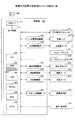
図15は、ライン方式の画像形成装置100のヘッドの配置とテストパターンを模式的に説明する図の一例である。ヘッド固定ブラケット160はシート材搬送方向と直交する主走査方向の端から端まで掛け渡されるように固定されている。ヘッド固定ブラケット160には、上流側からKCMYのインクの記録ヘッド180がそれぞれ主走査方向の全域に配置されている。各色の記録ヘッド180は端部が重複するように千鳥状に配置されている。こうすることで、記録ヘッド180の端部でも十分な解像度が得られる液滴が吐出されるので、主走査方向の全域に1つの記録ヘッド180を配置する必要がなくコスト増を抑制できる。なお、各色毎に主走査方向の全域に1つの記録ヘッド180を配置してもよいし、各色の記録ヘッド180の主走査方向の重複領域をより長くしてもよい。 FIG. 15 is an example of a diagram for schematically explaining the head arrangement and the test pattern of the line type
ヘッド固定ブラケット160よりも下流にはセンサ固定ブラケット170が、シート材搬送方向と直交する主走査方向の端から端まで掛け渡されるように固定されている。センサ固定ブラケット170には、印字位置ずれセンサ30がヘッドの数だけ配置されている。すなわち、1つの印字位置ずれセンサ30は、1つの記録ヘッド180と、主走査方向に少なくとも一部が重複するように配置されている。また、1つの印字位置ずれセンサ30は、1対の発光素子402と受光素子403を有する。発光素子402と受光素子403は、主走査方向にほぼ並行に並列配置されている。図15の場合、液滴位置ずれセンサ30は移動しないので、例えば副走査駆動部314が特許請求の範囲の相対移動手段に相当する。 A
このような形態の画像形成装置100は、テストパターンを構成する各ラインを、ラインの長手方向が主走査方向と並行になるように形成する。Kを基準に他の色の液滴の着弾位置ずれを補正する場合、画像形成装置100は、KのラインとMのライン、KのラインとCのライン、KのラインとYのラインを形成する。そして、シリアル方式の画像形成装置100と同様に、CMYKのテストパターンのエッジ位置を検出し、その位置ずれ量から液滴吐出タイミングを補正する。 The
以上のように、ライン方式の画像形成装置100においても、適切に印字位置ずれセンサ30を配置することで着弾位置ずれを補正できる。 As described above, also in the line type
〔動作手順〕
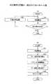
図16は、補正処理実行部526が信号補正する手順の一例を示すフローチャート図である。[Operation procedure]
FIG. 16 is a flowchart illustrating an example of a procedure in which the correction
まず、CPU301が、着弾位置ずれ補正を開始するよう主制御部310に指示する。この指示により、主制御部310は副走査駆動部314を介して副走査モータ132を駆動しシート材150を記録ヘッド21の真下まで搬送させる(S1)。 First, the
次に、主制御部310は主走査駆動部313を介して主走査モータ27を駆動して、キャリッジ5をシート材150上に移動し、シート材150上の特定の箇所にて発光素子と受光素子のキャリブレーションを実施する(S2)。 Next, the
図17(a)はS2の処理を説明するフローチャート図の一例である。キャリブレーションは、発光素子の検出電圧が所望の範囲内(具体的には4V±0.2Vの範囲内に調整している。)になるように発光素子の光量を調整する処理である。 FIG. 17A is an example of a flowchart for explaining the process of S2. The calibration is a process of adjusting the light amount of the light emitting element so that the detection voltage of the light emitting element is within a desired range (specifically, adjusted within the range of 4V ± 0.2V).
CPU301によって発光制御手段511に印字位置ずれセンサ30の発光素子402を駆動するためのPWM値が設定され、平滑回路512で平滑化された後、駆動回路513に与えられることで、駆動回路513が発光素子402を発光駆動する(S21)。 The
印字位置ずれセンサ30の受光素子403が検出した強度信号は共有メモリ525に記憶され、CPU301が所望の出力値(電圧値)になっているか判定する(S22)。 The intensity signal detected by the
所望の電圧値になっていれば(S22のOK)、図17(a)の処理や終了する。所望の電圧値になっていなければ(S22のNo)、CPU301はPWM値を変更し(S23)、再調整を行う。 If the desired voltage value is reached (OK in S22), the processing in FIG. If it is not the desired voltage value (No in S22), the
次に、主走査制御部313が主走査駆動モータ27を介してキャリッジ5を移動させると共に、ヘッド駆動制御部312が記録ヘッド21〜24を駆動して着弾位置ずれ調整用のテストパターンを印刷する(S3)。 Next, the main
次に、主走査制御部313が主走査駆動モータ27を介してキャリッジ5を移動させることで、印字位置ずれセンサ30はテストパターンを読み取り検出電圧データを共有メモリ525に記憶する(S4)。 Next, when the main
図17(b)はS4の処理を説明するフローチャート図の一例である。まず、CPU301が発光素子402を点灯させる(S41)。 FIG. 17B is an example of a flowchart for explaining the process of S4. First, the
次に、光電変換回路521等が検出電圧データの取り込みを開始する(S42)。取り込みを開始したら、主走査駆動部313は主走査駆動モータ27によりキャリッジ5を移動させていく(S43)。つまり、キャリッジ5が移動ながら、光電変換回路521等が検出電圧データを取り込む。データのサンプリングは例えば20kHz(50μs間隔)である。 Next, the
キャリッジ5が画像形成装置100の端部に到達すると、光電変換回路521等は検出電圧データの取り込みを終了する(S44)。FPGA306は一連の検出電圧データを共有メモリ525に蓄積する。CPU301はキャリッジ5をホームポジションで停止させる(S45)。 When the
図16に戻り、補正処理実行部526は、検出電圧を用いて液滴吐出タイミングを補正する(S5)。すなわち、閾値決定部601が変曲点から下限閾値Vrdと上限閾値Vruを決定して、吐出タイミング補正部603が下限閾値Vrdと上限閾値Vruから交点C1,C2を求める。交点C1とC2の中点がテストパターンを構成するラインの位置である。吐出タイミング補正部603は各ラインの距離を適正距離と比較して着弾位置ずれ量を算出し、着弾位置ずれがなくなるように記録ヘッド21を駆動するときの液滴吐出タイミングの補正値を算出する。 Returning to FIG. 16, the correction
以上説明したように、本実施形態の画像形成装置100は、変曲点を含むように決定された下限閾値Vrdと上限閾値Vruによりエッジ位置も特定するので、液滴の着弾位置ずれを精度よく補正することができる。 As described above, the
本実施例では、液滴吐出タイミングの補正値の算出を画像形成装置でなく、サーバが行う画像形成システムについて説明する。 In this embodiment, a description will be given of an image forming system in which a correction value of a droplet discharge timing is calculated by a server rather than an image forming apparatus.
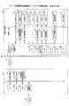
図18は、画像形成装置100とサーバ200を有する画像形成システム500を模式的に説明する図の一例である。図18において図3と同一部には同一の符号を付しその説明は省略する。画像形成装置100とサーバ200がネットワーク201を介して接続されている。ネットワーク201は、社内のLAN、LAN同士を接続したWAN,若しくは、インターネット、又は、これらを組み合わせたものである。 FIG. 18 is an example of a diagram schematically illustrating an
図18のような画像形成システム500では、画像形成装置100がテストパターンの形成及び印字位置ずれセンサによるテストパターンの走査を行い、サーバ200が液滴吐出タイミングの補正値を算出する。したがって、画像形成装置100の処理負荷を低減でき、サーバ200に液滴吐出タイミングの補正値の算出機能を集約できる。 In an
図19は、サーバ200と画像形成装置100のハードウェア構成図の一例を示す図である。サーバ200は、それぞれバスで相互に接続されているCPU51、ROM52、RAM53、記憶媒体装着部54、通信装置55、入力装置56、及び、記憶装置57を有する。CPU51は、OS(Operating System)、及び、プログラム570を記憶装置57から読み出して、RAM53を作業メモリにして実行する。このプログラム570は、液滴吐出タイミングの補正値を算出する処理を行う。 FIG. 19 is a diagram illustrating an example of a hardware configuration diagram of the
RAM53は必要なデータを一時保管する作業メモリ(主記憶メモリ)になり、ROM52にはBIOSや初期設定されたデータ、ブートストラップロータ等が記憶されている。記憶媒体装着部54は、可搬型の記憶媒体320を装着するインタフェースである。 The
通信装置55は、LANカードやイーサネット(登録商標)カードと呼ばれ、ネットワーク201に接続して、画像形成装置100の外部I/F311と通信する。なお、画像形成装置100には、少なくともサーバ200のIPアドレス又はドメイン名が登録されている。 The
入力装置56は、キーボード、マウスなど、ユーザの様々な操作指示を受け付けるユーザインターフェイスである。タッチパネルや音声入力装置を入力装置とすることもできる。 The
記憶装置57は、HDD(Hard Disk Drive)やフラッシュメモリなどの不揮発メモリを実体とし、OS、プログラム等を記憶している。プログラム570は、記憶媒体320に記録された状態又は不図示のサーバ200からダウンロードされる態様で配布される。 The
図20は、画像形成システム500の機能ブロック図の一例である。図20において図7と同一構成部の説明は省略する。本実施例の画像形成装置100は補正処理実行部526を有さず、サーバ側が補正処理実行部526を有する。このため、画像形成装置100は共有メモリ525とヘッド駆動部312を有する構成になる。 FIG. 20 is an example of a functional block diagram of the
補正処理実行部526は、閾値決定部601,変曲点決定部602及び吐出タイミング補正部603を有するが、これらの機能は実施例1と同様である。 The correction
画像形成システム500は、サーバが液滴吐出タイミングの補正値を算出するので、画像形成装置は共有メモリ525に記憶された検出電圧データをサーバ200に送信する。図では、同じ検出電圧データが2回、送信されるように見えるが、送信は1回でよい。 In the
サーバ側の補正処理実行部526は閾値の決定と変曲点の決定を行って、液滴吐出タイミングの補正値を算出する。サーバ200は液滴吐出タイミングの補正値を画像形成装置100に送信するので、画像形成装置100のヘッド駆動制御部312は吐出タイミングを変更することができる。 The correction
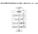
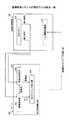
図21は、画像形成システム500の動作手順を示すフローチャート図の一例である。図示するように図16のS5のみをサーバ200が行い、これら以外の処理S1〜S4を画像形成装置100が行う。 FIG. 21 is an example of a flowchart showing an operation procedure of the
また、画像形成装置100とサーバ200が通信するため、画像形成装置100は、ステップS4-1において検出電圧データを送信する処理、S4-2において液滴吐出タイミングの補正値を受信する処理を新たに行う。 In addition, since the
これに対し、サーバ200は、S4-3において検出電圧データを受信する処理、及び、S5-1において液滴吐出タイミングの補正値を画像形成装置100に送信する処理を新たに行う。 On the other hand, the
このように、処理が行われる場所が変わるだけで、画像形成システム500は、実施例1と同様に、シート材の特性から受ける影響を抑制して、液滴吐出タイミングを高精度に補正することができる。 In this way, just by changing the place where the processing is performed, the
1 ガイドロッド
2 副ガイド
5 キャリッジ
7 駆動プーリ
8 主走査モータ
9 タイミングベルト
21〜24 記録ヘッド
30 印字位置ずれセンサ
41 エンコーダシート
42 エンコーダセンサ
100 画像形成装置
200 サーバ
301 CPU
310 主制御部
312 ヘッド駆動制御部
313 主走査駆動部
314 副走査駆動部
402 発光素子
403 受光素子
500 画像形成システム
525 共有メモリ
526 補正処理実行部
601 閾値決定部
602 変曲点決定部
603 吐出タイミング補正部DESCRIPTION OF
310
Claims (8)
Translated fromJapaneseテストパターンのパターンデータを取得して前記記録媒体にテストパターンを形成する画像形成手段と、
前記記録媒体に光を照射する発光手段及び前記記録媒体からの反射光を受光する受光手段とを有する読み取り手段と、
前記記録媒体又は前記読み取り手段を等速で移動させる相対移動手段と、
テストパターン上を前記光が移動している間、前記受光手段が前記光の走査位置から受光した前記反射光の強度データを取得する強度データ取得手段と、
前記強度データの着目値の上下方向にそれぞれ所定数のデータを抽出し、上側及び下側のデータの回帰曲線の切片の差が最も小さくなる前記着目値を変曲点に決定する変曲点算出手段と、
前記変曲点を前記ラインの位置に決定する位置検出手段と、
を有することを特徴とする画像形成装置。An image forming apparatus that reads a test patternincluding one or more lines formed by discharging droplets on a recording medium and adjusts the discharge timing of the droplets,
Image forming means for acquiring test pattern data and forming a test pattern on the recording medium;
A reading means having a light emitting means for irradiating the recording medium with light and a light receiving means for receiving reflected light from the recording medium ;
Relative moving means for moving the recording medium or the reading means at a constant speed;
Intensity data acquisition means for acquiring intensity data of the reflected light received by the light receiving means from the scanning position of the light while the light is moving on the test pattern;
Inflection point calculation that extracts a predetermined number of data in the vertical direction of the attention value of the intensity data and determines the inflection point as the inflection point at which the difference between the regression curve intercepts the upper and lower data becomes the smallest Means ,
A position detection meansthat determine the inflection point to the position of the line,
An image forming apparatus comprising:
テストパターンのパターンデータを取得して前記記録媒体にテストパターンを形成する画像形成手段と、
前記記録媒体に光を照射する発光手段及び前記記録媒体からの反射光を受光する受光手段とを有する読み取り手段と、
前記記録媒体又は前記読み取り手段を等速で移動させる相対移動手段と、
テストパターン上を前記光が移動している間、前記受光手段が前記光の走査位置から受光した前記反射光の強度データを取得する強度データ取得手段と、
前記強度データの着目値の上下方向にそれぞれ所定数のデータを抽出し、前記着目値を中心に上側又は下側の各データを180度回転させ、前記着目値より上側のデータの回帰曲線と下側のデータの回帰曲線の係数を算出し、両者の係数が最も一致する前記着目値を変曲点に決定する変曲点算出手段と、
前記変曲点を前記ラインの位置に決定する位置検出手段と、を有する画像形成装置。An image forming apparatus that reads a test patternincluding one or more lines formed by discharging droplets on a recording medium and adjusts the discharge timing of the droplets,
Image forming means for acquiring test pattern data and forming a test pattern on the recording medium;
A reading means having a light emitting means for irradiating the recording medium with light and a light receiving means for receiving reflected light from the recording medium ;
Relative moving means for moving the recording medium or the reading means at a constant speed;
Intensity data acquisition means for acquiring intensity data of the reflected light received by the light receiving means from the scanning position of the light while the light is moving on the test pattern;
A predetermined number of data is extracted in the vertical direction of the target value of the intensity data, each of the upper and lower data is rotated by 180 degrees around the target value, and the regression curve of the data above the target value and lower An inflection point calculating means for calculating a coefficient of a regression curve of the data on the side, and determining the inflection point as the target value at which the two coefficients are the best match;
An image forming apparatus comprising: position detection means for determining theinflection point as the position of the line.
ことを特徴とする請求項1又は2に記載の画像形成装置。The relative movement unit moves the reading unit in the main scanning direction with respect to the recording medium, thereby causing the light to cross the plurality of lines.
The image forming apparatus according toclaim 1, wherein the image forming apparatus is an image forming apparatus.
ことを特徴とする請求項1又は2に記載の画像形成装置。The relative movement means, by moving the recording medium in the sub-scanning read査方 direction relative to said reading means, to traverse a plurality of said lines to said light,
The image forming apparatus according toclaim 1, wherein the image forming apparatus is an image forming apparatus.
発光手段が前記記録媒体に光を照射し、受光手段が前記記録媒体からの反射光を受光するステップと、
相対移動手段が、前記記録媒体又は前記発光手段と前記受光手段を等速で移動させるステップと、
強度データ取得手段が、テストパターンを前記光が横断している間、前記受光手段が前記光の走査位置から受光した前記反射光の強度データを取得するステップと、
変曲点算出手段が、前記強度データの着目値の上下方向にそれぞれ所定数のデータを抽出し、上側及び下側のデータの回帰曲線の切片の差が最も小さくなる前記着目値を変曲点に決定するステップと、
位置検出手段が、前記変曲点を前記ラインの位置に決定するステップと、
を有するパターン位置検出方法。A pattern position detection method for an image forming apparatus that reads a test patternincluding one or more lines formed by discharging droplets on a recording medium and adjusts the discharge timing of the droplets,
A light emitting means irradiates the recording medium with light, and a light receiving means receives reflected light from the recording medium;
A relative moving means moving the recording medium or the light emitting means and the light receiving means at a constant speed;
An intensity data acquisition means for acquiring intensity data of the reflected light received from the light scanning position by the light receiving means while the light traverses a test pattern;
The inflection point calculation means extracts a predetermined number of data in the vertical direction of the target value of the intensity data, and sets the target value at which the difference between the intercepts of the regression curves of the upper and lower data is the smallest. Steps to determine
Position detecting means, the stepsthat determine the inflection point to the position of the line,
A pattern position detection method comprising:
発光手段が前記記録媒体に光を照射し、受光手段が前記記録媒体からの反射光を受光するステップと、 A light emitting means irradiates the recording medium with light, and a light receiving means receives reflected light from the recording medium;
相対移動手段が、前記記録媒体又は前記発光手段と前記受光手段を等速で移動させるステップと、 A relative moving means moving the recording medium or the light emitting means and the light receiving means at a constant speed;
強度データ取得手段が、テストパターンを前記光が横断している間、前記受光手段が前記光の走査位置から受光した前記反射光の強度データを取得するステップと、 An intensity data acquisition means for acquiring intensity data of the reflected light received from the light scanning position by the light receiving means while the light traverses a test pattern;
変曲点算出手段が、前記強度データの着目値の上下方向にそれぞれ所定数のデータを抽出し、前記着目値を中心に上側又は下側の各データを180度回転させ、前記着目値より上側のデータの回帰曲線と下側のデータの回帰曲線の係数を算出し、両者の係数が最も一致する前記着目値を変曲点に決定するステップと、 The inflection point calculating means extracts a predetermined number of data in the vertical direction of the target value of the intensity data, rotates each upper or lower data by 180 degrees around the target value, and is above the target value. Calculating a coefficient of the regression curve of the data of the data and the regression curve of the lower data, and determining the inflection point as the value of interest where the coefficients of the two are the best match;
位置検出手段が、前記変曲点を前記ラインの位置に決定するステップと、を有するパターン位置検出方法。 And a step of determining position of the inflection point as the position of the line.
テストパターンのパターンデータを取得して前記記録媒体にテストパターンを形成する画像形成手段と、
前記記録媒体に光を照射する発光手段及び前記記録媒体からの反射光を受光する受光手段とを有する読み取り手段と、
前記記録媒体又は前記読み取り手段を等速で移動させる相対移動手段と、
テストパターン上を前記光が移動している間、前記受光手段が前記光の走査位置から受光した前記反射光の強度データを取得する強度データ取得手段と、を備える画像形成装置と、
テストパターンのパターンデータを記憶するパターンデータ記憶手段と、
前記強度データの着目値の上下方向にそれぞれ所定数のデータを抽出し、上側及び下側のデータの回帰曲線の切片の差が最も小さくなる前記着目値を変曲点に決定する変曲点算出手段と、
前記変曲点を前記ラインの位置に決定する位置検出手段と、
を有する画像形成システム。An image forming system that reads a test patternincluding one or more lines formed by discharging droplets on a recording medium and adjusts the discharge timing of the droplets,
Image forming means for acquiring test pattern data and forming a test pattern on the recording medium;
A reading means having a light emitting means for irradiating the recording medium with light and a light receiving means for receiving reflected light from the recording medium ;
Relative moving means for moving the recording medium or the reading means at a constant speed;
An image forming apparatus comprising: intensity data acquisition means for acquiring intensity data of the reflected light received from the light scanning position by the light receiving means while the light is moving on the test pattern;
Pattern data storage means for storing test pattern data;
Inflection point calculation that extracts a predetermined number of data in the vertical direction of the attention value of the intensity data and determines the inflection point as the inflection point at which the difference between the regression curve intercepts the upper and lower data becomes the smallest Means ,
A position detection meansthat determine the inflection point to the position of the line,
An image forming system.
テストパターンのパターンデータを取得して前記記録媒体にテストパターンを形成する画像形成手段と、
前記記録媒体に光を照射する発光手段及び前記記録媒体からの反射光を受光する受光手段とを有する読み取り手段と、
前記記録媒体又は前記読み取り手段を等速で移動させる相対移動手段と、
テストパターン上を前記光が移動している間、前記受光手段が前記光の走査位置から受光した前記反射光の強度データを取得する強度データ取得手段と、を備える画像形成装置と、
テストパターンのパターンデータを記憶するパターンデータ記憶手段と、
前記強度データの着目値の上下方向にそれぞれ所定数のデータを抽出し、前記着目値を中心に上側又は下側の各データを180度回転させ、前記着目値より上側のデータの回帰曲線と下側のデータの回帰曲線の係数を算出し、両者の係数が最も一致する前記着目値を変曲点に決定する変曲点算出手段と、
前記変曲点を前記ラインの位置に決定する位置検出手段と、を有する画像形成システム。An image forming system that reads a test pattern including one or more lines formed by discharging droplets on a recording medium and adjusts the discharge timing of the droplets,
Image forming means for acquiring test pattern data and forming a test pattern on the recording medium;
A reading means having a light emitting means for irradiating the recording medium with light and a light receiving means for receiving reflected light from the recording medium;
Relative moving means for moving the recording medium or the reading means at a constant speed;
An image forming apparatus comprising: intensity data acquisition means for acquiring intensity data of the reflected light received from the light scanning position by the light receiving means while the light is moving on the test pattern;
Pattern data storage means for storing test pattern data;
A predetermined number of data is extracted in the vertical direction of the target value of the intensity data, each of the upper and lower data is rotated by 180 degrees around the target value, and the regression curve of the data above the target value and lower An inflection point calculating means for calculating a coefficient of a regression curve of the data on the side, and determining the inflection point as the target value at which the two coefficients are the best match;
An image forming system comprising: position detecting means for determining the inflection point as the position of the line .
Priority Applications (2)
| Application Number | Priority Date | Filing Date | Title |
|---|---|---|---|
| JP2011276399AJP5938890B2 (en) | 2011-02-24 | 2011-12-16 | Image forming apparatus, pattern position detecting method, and image forming system |
| US13/397,133US9290028B2 (en) | 2011-02-24 | 2012-02-15 | Image forming apparatus, pattern position determining method, and image forming system |
Applications Claiming Priority (3)
| Application Number | Priority Date | Filing Date | Title |
|---|---|---|---|
| JP2011038742 | 2011-02-24 | ||
| JP2011038742 | 2011-02-24 | ||
| JP2011276399AJP5938890B2 (en) | 2011-02-24 | 2011-12-16 | Image forming apparatus, pattern position detecting method, and image forming system |
Publications (2)
| Publication Number | Publication Date |
|---|---|
| JP2012187913A JP2012187913A (en) | 2012-10-04 |
| JP5938890B2true JP5938890B2 (en) | 2016-06-22 |
Family
ID=46718808
Family Applications (1)
| Application Number | Title | Priority Date | Filing Date |
|---|---|---|---|
| JP2011276399AExpired - Fee RelatedJP5938890B2 (en) | 2011-02-24 | 2011-12-16 | Image forming apparatus, pattern position detecting method, and image forming system |
Country Status (2)
| Country | Link |
|---|---|
| US (1) | US9290028B2 (en) |
| JP (1) | JP5938890B2 (en) |
Families Citing this family (9)
| Publication number | Priority date | Publication date | Assignee | Title |
|---|---|---|---|---|
| JP6326793B2 (en) | 2012-12-05 | 2018-05-23 | 株式会社リコー | Image forming apparatus, image displacement adjustment method, and image displacement adjustment program |
| JP6119218B2 (en)* | 2012-12-05 | 2017-04-26 | 株式会社リコー | Image forming apparatus, program, and image forming system |
| JP6164944B2 (en)* | 2013-06-13 | 2017-07-19 | キヤノン株式会社 | Measuring method |
| JP6569302B2 (en) | 2015-05-27 | 2019-09-04 | 株式会社リコー | Image forming apparatus, method for adjusting image forming apparatus, and program |
| JP6743129B2 (en)* | 2016-03-18 | 2020-08-19 | テルモ株式会社 | Heart function measuring device, heart function measuring method, and heart function measuring program |
| US10207495B2 (en) | 2016-11-22 | 2019-02-19 | Ricoh Company, Ltd. | Image forming apparatus, method for calculating actual distance of deviation, and computer program product storing same |
| US10286699B2 (en) | 2016-11-22 | 2019-05-14 | Ricoh Company, Ltd. | Imaging device, image forming apparatus, and method for detecting deviation of landing position |
| JP6911335B2 (en) | 2016-11-25 | 2021-07-28 | 株式会社リコー | Image forming device and program |
| JP7326842B2 (en)* | 2019-04-23 | 2023-08-16 | ブラザー工業株式会社 | Liquid ejector |
Family Cites Families (22)
| Publication number | Priority date | Publication date | Assignee | Title |
|---|---|---|---|---|
| JPS58213205A (en)* | 1983-05-16 | 1983-12-12 | Hitachi Ltd | Microscopic dimension measuring device |
| JPS63195616A (en)* | 1987-02-10 | 1988-08-12 | Nikon Corp | focus control device |
| JPH0245886A (en)* | 1988-08-08 | 1990-02-15 | Nippon Telegr & Teleph Corp <Ntt> | Method for measuring edge position |
| JP3460872B2 (en)* | 1994-11-04 | 2003-10-27 | 株式会社リコー | Position detection method and positioning device |
| JP2001129980A (en) | 1999-11-02 | 2001-05-15 | Ricoh Co Ltd | Ink jet recording device and printer driver |
| JP2005148299A (en) | 2003-11-13 | 2005-06-09 | Kyocera Mita Corp | Image density adjustment method and device for image forming apparatus |
| JP2006082502A (en)* | 2004-09-17 | 2006-03-30 | Konica Minolta Medical & Graphic Inc | Inkjet recording apparatus and inkjet recording method |
| JP5122794B2 (en) | 2006-11-27 | 2013-01-16 | 株式会社リコー | Image forming apparatus |
| JP5004622B2 (en) | 2007-03-17 | 2012-08-22 | 株式会社リコー | Image forming apparatus and landing position deviation correction method |
| JP4949094B2 (en)* | 2007-03-17 | 2012-06-06 | 株式会社リコー | Image forming apparatus |
| JP4999505B2 (en)* | 2007-03-17 | 2012-08-15 | 株式会社リコー | Image forming apparatus and landing position deviation correction method |
| JP5081338B2 (en) | 2007-03-17 | 2012-11-28 | 株式会社リコー | Liquid ejection apparatus and image forming apparatus |
| JP5081339B2 (en) | 2007-03-19 | 2012-11-28 | 株式会社リコー | Image forming apparatus |
| JP2009006609A (en) | 2007-06-28 | 2009-01-15 | Ricoh Co Ltd | Image forming apparatus and defective nozzle determination method |
| JP5043614B2 (en) | 2007-12-05 | 2012-10-10 | 株式会社リコー | Image forming apparatus and carriage |
| JP5073509B2 (en) | 2008-01-17 | 2012-11-14 | 株式会社リコー | Image forming apparatus and landing position deviation correction method |
| JP5091693B2 (en) | 2008-01-18 | 2012-12-05 | 株式会社リコー | Image forming apparatus |
| JP5107735B2 (en) | 2008-01-28 | 2012-12-26 | 株式会社リコー | Image forming apparatus |
| JP2011051152A (en)* | 2009-08-31 | 2011-03-17 | Seiko Epson Corp | Liquid ejecting device and ejection inspecting method |
| JP5463883B2 (en) | 2009-12-03 | 2014-04-09 | 株式会社リコー | Image forming apparatus |
| JP5663867B2 (en) | 2009-12-07 | 2015-02-04 | 株式会社リコー | Image forming apparatus |
| JP5353755B2 (en) | 2010-02-19 | 2013-11-27 | 株式会社リコー | Image forming apparatus |
- 2011
- 2011-12-16JPJP2011276399Apatent/JP5938890B2/ennot_activeExpired - Fee Related
- 2012
- 2012-02-15USUS13/397,133patent/US9290028B2/ennot_activeExpired - Fee Related
Also Published As
| Publication number | Publication date |
|---|---|
| US9290028B2 (en) | 2016-03-22 |
| US20120218568A1 (en) | 2012-08-30 |
| JP2012187913A (en) | 2012-10-04 |
Similar Documents
| Publication | Publication Date | Title |
|---|---|---|
| JP5938890B2 (en) | Image forming apparatus, pattern position detecting method, and image forming system | |
| JP5962000B2 (en) | Image forming apparatus, pattern position determining method, and image forming system | |
| JP6119218B2 (en) | Image forming apparatus, program, and image forming system | |
| JP5998468B2 (en) | Image forming apparatus, pattern position determining method, and image forming system | |
| JP2013049261A (en) | Image forming apparatus, pattern position determining method, and image forming system | |
| JP2014028463A (en) | Image forming apparatus, pattern position detection method, image formation system, and method for producing printed matter | |
| US20080231649A1 (en) | Image forming apparatus, method for correcting displacement of landing positions | |
| JP5091693B2 (en) | Image forming apparatus | |
| JP5533037B2 (en) | Image forming apparatus | |
| JP6061550B2 (en) | Recording apparatus and control method thereof | |
| CN110949003B (en) | Liquid ejecting apparatus, liquid ejecting method, and storage medium | |
| US10639916B2 (en) | Conveyance device, conveyance system, and head unit position adjusting method | |
| JP5961999B2 (en) | Image forming apparatus, pattern position determining method, and image forming system | |
| JP2014054772A (en) | Image forming apparatus, pattern position detection method, program, method for manufacturing printed matter | |
| US20140153006A1 (en) | Image forming apparatus, method of adjusting image positional deviation, and computer program product | |
| JP6364806B2 (en) | Image forming apparatus, recording medium type determination system, and recording medium type determination method | |
| JP2010030161A (en) | Image formation device | |
| JP5919771B2 (en) | Image forming apparatus, pattern position detecting method, and image forming system | |
| JP2013049267A (en) | Image forming apparatus, pattern position determining method, program, and printed matter manufacturing method | |
| JP2013099866A (en) | Image forming apparatus, pattern position detecting method, image forming system | |
| JP2013099865A (en) | Image forming apparatus, pattern position detecting method | |
| JP2017124555A (en) | Pattern, recording position deciding device, image formation device, and program | |
| JP5286722B2 (en) | Image forming apparatus | |
| JP5200783B2 (en) | Image forming apparatus |
Legal Events
| Date | Code | Title | Description |
|---|---|---|---|
| A621 | Written request for application examination | Free format text:JAPANESE INTERMEDIATE CODE: A621 Effective date:20141118 | |
| A977 | Report on retrieval | Free format text:JAPANESE INTERMEDIATE CODE: A971007 Effective date:20150918 | |
| A131 | Notification of reasons for refusal | Free format text:JAPANESE INTERMEDIATE CODE: A131 Effective date:20150929 | |
| A521 | Request for written amendment filed | Free format text:JAPANESE INTERMEDIATE CODE: A523 Effective date:20151126 | |
| TRDD | Decision of grant or rejection written | ||
| A01 | Written decision to grant a patent or to grant a registration (utility model) | Free format text:JAPANESE INTERMEDIATE CODE: A01 Effective date:20160419 | |
| A61 | First payment of annual fees (during grant procedure) | Free format text:JAPANESE INTERMEDIATE CODE: A61 Effective date:20160502 | |
| R151 | Written notification of patent or utility model registration | Ref document number:5938890 Country of ref document:JP Free format text:JAPANESE INTERMEDIATE CODE: R151 | |
| LAPS | Cancellation because of no payment of annual fees |