JP5937191B2 - Method for transmitting and receiving information and associated IOT device - Google Patents
Method for transmitting and receiving information and associated IOT deviceDownload PDFInfo
- Publication number
- JP5937191B2 JP5937191B2JP2014254655AJP2014254655AJP5937191B2JP 5937191 B2JP5937191 B2JP 5937191B2JP 2014254655 AJP2014254655 AJP 2014254655AJP 2014254655 AJP2014254655 AJP 2014254655AJP 5937191 B2JP5937191 B2JP 5937191B2
- Authority
- JP
- Japan
- Prior art keywords
- information
- multicast
- address field
- sliced
- iot device
- Prior art date
- Legal status (The legal status is an assumption and is not a legal conclusion. Google has not performed a legal analysis and makes no representation as to the accuracy of the status listed.)
- Active
Links
- 238000000034methodMethods0.000titleclaimsdescription51
- 238000012545processingMethods0.000claimsdescription12
- 238000004891communicationMethods0.000description62
- 230000005540biological transmissionEffects0.000description15
- 238000010586diagramMethods0.000description11
- 230000006870functionEffects0.000description11
- 238000013507mappingMethods0.000description5
- 230000003466anti-cipated effectEffects0.000description2
- 238000005516engineering processMethods0.000description2
- 239000004065semiconductorSubstances0.000description2
- 238000013461designMethods0.000description1
- 238000011161developmentMethods0.000description1
- 239000000284extractSubstances0.000description1
- 238000012905input functionMethods0.000description1
- 230000008447perceptionEffects0.000description1
- 230000001360synchronised effectEffects0.000description1
Images


Classifications
- H—ELECTRICITY
- H04—ELECTRIC COMMUNICATION TECHNIQUE
- H04W—WIRELESS COMMUNICATION NETWORKS
- H04W48/00—Access restriction; Network selection; Access point selection
- H04W48/08—Access restriction or access information delivery, e.g. discovery data delivery
- H—ELECTRICITY
- H04—ELECTRIC COMMUNICATION TECHNIQUE
- H04W—WIRELESS COMMUNICATION NETWORKS
- H04W48/00—Access restriction; Network selection; Access point selection
- H04W48/08—Access restriction or access information delivery, e.g. discovery data delivery
- H04W48/10—Access restriction or access information delivery, e.g. discovery data delivery using broadcasted information
- H—ELECTRICITY
- H04—ELECTRIC COMMUNICATION TECHNIQUE
- H04W—WIRELESS COMMUNICATION NETWORKS
- H04W12/00—Security arrangements; Authentication; Protecting privacy or anonymity
- H04W12/03—Protecting confidentiality, e.g. by encryption
- H—ELECTRICITY
- H04—ELECTRIC COMMUNICATION TECHNIQUE
- H04W—WIRELESS COMMUNICATION NETWORKS
- H04W12/00—Security arrangements; Authentication; Protecting privacy or anonymity
- H04W12/04—Key management, e.g. using generic bootstrapping architecture [GBA]
- H—ELECTRICITY
- H04—ELECTRIC COMMUNICATION TECHNIQUE
- H04W—WIRELESS COMMUNICATION NETWORKS
- H04W12/00—Security arrangements; Authentication; Protecting privacy or anonymity
- H04W12/50—Secure pairing of devices
- H—ELECTRICITY
- H04—ELECTRIC COMMUNICATION TECHNIQUE
- H04W—WIRELESS COMMUNICATION NETWORKS
- H04W12/00—Security arrangements; Authentication; Protecting privacy or anonymity
- H04W12/60—Context-dependent security
- H04W12/69—Identity-dependent
- H04W12/73—Access point logical identity
- H—ELECTRICITY
- H04—ELECTRIC COMMUNICATION TECHNIQUE
- H04W—WIRELESS COMMUNICATION NETWORKS
- H04W72/00—Local resource management
- H04W72/30—Resource management for broadcast services
- H—ELECTRICITY
- H04—ELECTRIC COMMUNICATION TECHNIQUE
- H04W—WIRELESS COMMUNICATION NETWORKS
- H04W80/00—Wireless network protocols or protocol adaptations to wireless operation
- H04W80/02—Data link layer protocols
- H—ELECTRICITY
- H04—ELECTRIC COMMUNICATION TECHNIQUE
- H04L—TRANSMISSION OF DIGITAL INFORMATION, e.g. TELEGRAPHIC COMMUNICATION
- H04L63/00—Network architectures or network communication protocols for network security
- H04L63/04—Network architectures or network communication protocols for network security for providing a confidential data exchange among entities communicating through data packet networks
- H04L63/0428—Network architectures or network communication protocols for network security for providing a confidential data exchange among entities communicating through data packet networks wherein the data content is protected, e.g. by encrypting or encapsulating the payload
- H—ELECTRICITY
- H04—ELECTRIC COMMUNICATION TECHNIQUE
- H04W—WIRELESS COMMUNICATION NETWORKS
- H04W12/00—Security arrangements; Authentication; Protecting privacy or anonymity
- H04W12/02—Protecting privacy or anonymity, e.g. protecting personally identifiable information [PII]
- H—ELECTRICITY
- H04—ELECTRIC COMMUNICATION TECHNIQUE
- H04W—WIRELESS COMMUNICATION NETWORKS
- H04W4/00—Services specially adapted for wireless communication networks; Facilities therefor
- H04W4/70—Services for machine-to-machine communication [M2M] or machine type communication [MTC]
- H—ELECTRICITY
- H04—ELECTRIC COMMUNICATION TECHNIQUE
- H04W—WIRELESS COMMUNICATION NETWORKS
- H04W84/00—Network topologies
- H04W84/02—Hierarchically pre-organised networks, e.g. paging networks, cellular networks, WLAN [Wireless Local Area Network] or WLL [Wireless Local Loop]
- H04W84/10—Small scale networks; Flat hierarchical networks
- H04W84/12—WLAN [Wireless Local Area Networks]
- Y—GENERAL TAGGING OF NEW TECHNOLOGICAL DEVELOPMENTS; GENERAL TAGGING OF CROSS-SECTIONAL TECHNOLOGIES SPANNING OVER SEVERAL SECTIONS OF THE IPC; TECHNICAL SUBJECTS COVERED BY FORMER USPC CROSS-REFERENCE ART COLLECTIONS [XRACs] AND DIGESTS
- Y02—TECHNOLOGIES OR APPLICATIONS FOR MITIGATION OR ADAPTATION AGAINST CLIMATE CHANGE
- Y02D—CLIMATE CHANGE MITIGATION TECHNOLOGIES IN INFORMATION AND COMMUNICATION TECHNOLOGIES [ICT], I.E. INFORMATION AND COMMUNICATION TECHNOLOGIES AIMING AT THE REDUCTION OF THEIR OWN ENERGY USE
- Y02D30/00—Reducing energy consumption in communication networks
- Y02D30/70—Reducing energy consumption in communication networks in wireless communication networks
Landscapes
- Engineering & Computer Science (AREA)
- Computer Security & Cryptography (AREA)
- Computer Networks & Wireless Communication (AREA)
- Signal Processing (AREA)
- Mobile Radio Communication Systems (AREA)
- Data Exchanges In Wide-Area Networks (AREA)
- Small-Scale Networks (AREA)
- Computer Hardware Design (AREA)
- Computing Systems (AREA)
- General Engineering & Computer Science (AREA)
Description
Translated fromJapanese本発明の開示の実施形態は、無線通信に関し、より詳細には、モノのインターネット(Internet of Things:IoT)通信に関する。 Embodiments of the present disclosure relate to wireless communications, and more particularly to Internet of Things (IoT) communications.
情報技術の発展と共に、IoTは益々普及している。名が示す通り、IoTは多くの相互接続された装置を有するネットワークである。IoTは、知的な知覚、識別、及び相互接続機能を持ち、コンピュータ及びインターネットの後にやって来る情報産業の第3の波の部分である。 With the development of information technology, IoT is becoming increasingly popular. As the name suggests, IoT is a network with many interconnected devices. IoT has intelligent perception, identification, and interconnection capabilities, and is the third wave part of the information industry that comes after computers and the Internet.
モニタ及び高機能冷蔵庫のような多くのIoT装置にとって、WiFi(Wireless Fidelity)を通じてインターネットに接続し、それらがインターネットを介してユーザにより制御できるようにすることは望ましい。しかしながら、IoT装置は、キーパッド又はタッチパッドのような入力機能を有しなくても良い。したがって、指定されたアクセスポイント(AP)に接続するようこれらのIoT装置を制御する方法が問題になっている。 For many IoT devices, such as monitors and high-performance refrigerators, it is desirable to connect to the Internet through WiFi (Wireless Fidelity) so that they can be controlled by the user through the Internet. However, the IoT device may not have an input function such as a keypad or a touchpad. Therefore, how to control these IoT devices to connect to a designated access point (AP) is a problem.
本発明の目的の1つは、上述の問題を解決するために、情報を送信及び受信する方法、及び関連するIoT装置を提供することである。 One of the objects of the present invention is to provide a method for transmitting and receiving information and an associated IoT device in order to solve the above-mentioned problems.
本発明の第1の態様によると、情報を送信する方法であって、前記情報の少なくとも一部を少なくとも1つのマルチキャストIP(Internet Protocol)アドレスフィールドに書き込むステップと、前記少なくとも1つのマルチキャストIPアドレスフィールドに従って少なくとも1つのパケットを送信するステップと、を有する方法が開示される。一実施形態では、方法は、前記情報を生成するために、元の情報に識別子情報を挿入するような、元の情報に対して所定の処理を実行するステップを更に有する。 According to a first aspect of the present invention, there is provided a method for transmitting information, the step of writing at least part of the information in at least one multicast IP (Internet Protocol) address field, and the at least one multicast IP address field. And at least one packet is disclosed. In one embodiment, the method further comprises performing a predetermined process on the original information, such as inserting identifier information into the original information to generate the information.
本発明の第2の態様によると、情報を受信する方法であって、少なくとも1つのパケットを受信するステップと、前記情報の少なくとも一部を得るために、各パケットのマルチキャストMAC(Media Access Control)アドレスを読み取るステップと、を有する方法が開示される。 According to a second aspect of the present invention, there is provided a method for receiving information, the step of receiving at least one packet, and a multicast MAC (Media Access Control) of each packet in order to obtain at least part of the information A method comprising: reading an address.
本発明の第3の態様によると、情報を受信するIoT(モノのインターネット、Internet of Things:IoT)装置が開示される。IoT装置は、受信モジュールと、読み取りモジュールと、を有する。受信モジュールは、少なくとも1つのパケットを受信するよう配置される。読み取りモジュールは、前記情報の少なくとも一部を得るために、各パケットのマルチキャストMAC(Media Access Control)アドレスフィールドを読み取るよう配置される。 According to a third aspect of the present invention, an IoT (Internet of Things: IoT) device for receiving information is disclosed. The IoT device has a receiving module and a reading module. The receiving module is arranged to receive at least one packet. The reading module is arranged to read a multicast MAC (Media Access Control) address field of each packet to obtain at least part of the information.
本発明のこれらの及び他の目的は、以下の、種々の図面に示された好適な実施形態の詳細な説明を読んだ後に当業者に明らかになるだろう。 These and other objects of the present invention will become apparent to those skilled in the art after reading the following detailed description of the preferred embodiment shown in the various drawings.
特定の用語は、特定のシステムコンポーネントを表すために説明及び以下の請求項を通じて用いられる。当業者が理解するように、製造者等は1つのコンポーネントを異なる名称により参照し得る。本願明細書は、名称が異なるが機能が異ならないコンポーネント間の区別をしない。以下の議論及び請求項では、用語「有する(include、comprise)」は広義に用いられ、「・・・を含むが、・・・に限定されない」を意味すると解釈されるべきである。また、用語「結合する(couple)」は、間接的又は直接的な電気接続を意味することを意図する。したがって、ある装置が別の装置に結合する場合、その接続は、直接的な電気接続を通じて、又は他の装置及び接続を介した間接的な電気的接続を通じてもよい。 Certain terminology is used throughout the description and the following claims to refer to particular system components. As those skilled in the art will appreciate, manufacturers etc. may refer to a component by different names. The present specification makes no distinction between components that differ in name but not function. In the following discussion and claims, the term “include” is used broadly and should be interpreted to mean “including but not limited to”. The term “couple” is also intended to mean an indirect or direct electrical connection. Thus, when one device is coupled to another device, the connection may be through a direct electrical connection or through an indirect electrical connection through another device and connection.
指定されたAP(例えば、無線ルータ)に接続するようIoT装置を制御する幾つかの方法がある。第1の方法は、ピアツーピア(Peer−to−Peer、P2P)技術を介してIoT装置に接続するために、通信装置(例えば、スマートフォン又はノートブック)を用いても良い。次に、通信装置は、SSID(Service Set Identifier)及び/又はパスワードのようなAP構成情報をIoT装置へ送信するよう動作しても良い。その後、IoT装置は、受信したAP構成情報に従って指定されたAPに接続しても良い。第2の方法に関し、第1のステップで、IoT装置はAPモードに初期化されても良い。次に、通信装置は、SSID及び/又はパスワードのようなAP構成情報をIoT装置へ送信するために、IoT装置に接続されても良い。AP構成情報を受信した後に、IoT装置は、ステーションモードに切り替わり、次にAP構成情報に従って指定されたAPに接続しても良い。第3の方法に関し、第1のステップで、IoT装置は規定APへの接続を試みても良い。接続が確立された後、IoT装置は、TCP/IPプロトコルを通じて通信装置から、SSID及び/又はパスワードのようなAP構成情報を受信しても良い。その後、IoT装置は、AP構成情報に従って指定されたAPに接続する。第4の方法に関し、IoT装置は、スニファモードに初期化され、次に、パケットをスニフィングすることにより通信装置から送信されたパケットから、SSID及び/又はパスワードのようなAP構成情報をフェッチしても良い。このように、IoT装置は、指定されたAPに接続できる。 There are several ways to control an IoT device to connect to a designated AP (eg, a wireless router). The first method may use a communication device (eg, a smartphone or notebook) to connect to the IoT device via peer-to-peer (P2P) technology. Next, the communication device may operate to transmit AP configuration information such as an SSID (Service Set Identifier) and / or a password to the IoT device. Thereafter, the IoT device may connect to the designated AP according to the received AP configuration information. With respect to the second method, in the first step, the IoT device may be initialized to the AP mode. The communication device may then be connected to the IoT device to send AP configuration information such as an SSID and / or password to the IoT device. After receiving the AP configuration information, the IoT device may switch to the station mode and then connect to the AP specified according to the AP configuration information. With regard to the third method, in the first step, the IoT device may attempt to connect to the specified AP. After the connection is established, the IoT device may receive AP configuration information such as an SSID and / or password from the communication device through the TCP / IP protocol. Thereafter, the IoT device connects to the designated AP according to the AP configuration information. For the fourth method, the IoT device is initialized to sniffer mode, and then fetches AP configuration information such as SSID and / or password from the packet sent from the communication device by sniffing the packet. Also good. In this way, the IoT device can connect to the designated AP.
本発明は、主に第4の方法を対象にする。例示的な実施形態は、以下に開示される。スニファモードでは、IoT装置は、受信モジュール(例えば、WiFiチップ)を用いることにより、IoT装置が属する無線ネットワーク内でパケットを受信しても良い。非暗号化環境では、IoT装置は、パケット内の全ての平文データを読むことができる。IoT装置により読まれるために必要な情報は、パケットのデータフィールドに入れられ、ネットワークへ送信されても良い。IoT装置は、データを直接受信し及び使用できる。しかしながら、暗号化環境では、IoT装置は、パケットを解読し、読み、データを直接使用することができない。 The present invention is mainly directed to the fourth method. Exemplary embodiments are disclosed below. In the sniffer mode, the IoT device may receive a packet in a wireless network to which the IoT device belongs by using a reception module (for example, a WiFi chip). In a non-encrypted environment, the IoT device can read all plaintext data in the packet. Information necessary to be read by the IoT device may be placed in the data field of the packet and transmitted to the network. The IoT device can receive and use the data directly. However, in an encrypted environment, the IoT device cannot decrypt and read the packet and use the data directly.
802.11仕様によると、暗号化パケットではデータフィールドのみが暗号化され、ヘッダは暗号化されなままである。したがって、所望のデータがヘッダに入れられる場合、IoT装置は、スニファモードでヘッダからデータを引き出すことができる。しかしながら、多くの関連アプリケーションは、802.11ヘッダを直接変更できないので、ドライバが書き直される必要がある。802.11ヘッダに情報を挿入するための方法は、以下に開示される。 According to the 802.11 specification, in the encrypted packet only the data field is encrypted and the header remains unencrypted. Thus, if the desired data is put into the header, the IoT device can pull the data from the header in the sniffer mode. However, many related applications cannot directly change the 802.11 header, so the driver needs to be rewritten. A method for inserting information into the 802.11 header is disclosed below.
多くの現在主流のオペレーティングシステムは、マルチキャスト機能をサポートする。従来知られているように、マルチキャストIP(Internet Protocol)アドレスとマルチキャストMAC(Media Access Control)アドレスとの間には、マッピング関係が存在する。図1は、そのマッピング関係を示す図である。図1n示すように、IPv4(Internet Protocol version 4)では、IPアドレスフィールドの下位23ビットは、MACアドレスフィールドの下位23ビットにマッピングされる。IPv6(Internet Protocol version 6)では、IPアドレスフィールドの下位32ビットは、MACアドレスフィールドの下位32ビットにマッピングされる。802.11プロトコルによると、MACアドレスが用いられても良い。ここで、MACアドレスはヘッダに入れられる。この特性を用いることにより、IoT装置へ送信されるべきデータを802.11ヘッダに挿入することにより、802.11ヘッダを変更することが可能である。 Many current mainstream operating systems support multicast functionality. As is conventionally known, a mapping relationship exists between a multicast IP (Internet Protocol) address and a multicast MAC (Media Access Control) address. FIG. 1 is a diagram showing the mapping relationship. As shown in FIG. 1n, in IPv4 (Internet Protocol version 4), the lower 23 bits of the IP address field are mapped to the lower 23 bits of the MAC address field. In IPv6 (Internet Protocol version 6), the lower 32 bits of the IP address field are mapped to the lower 32 bits of the MAC address field. According to the 802.11 protocol, a MAC address may be used. Here, the MAC address is entered in the header. By using this property, it is possible to change the 802.11 header by inserting the data to be transmitted to the IoT device into the 802.11 header.
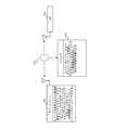
図2Aは、本発明の実施形態による無線通信ネットワークを示す図である。図2に示すように、無線通信ネットワーク100は、通信装置101、IoT装置102、及びAP103を有する。1より多い通信装置101が存在しても良く、通信装置101は、IPマルチキャストをサポートするノートブック、携帯電話機、PDA(Personal Digital Assistant)又はタブレットであっても良い。IoT装置102は、受信モジュール(例えば、WiFiチップ)を備えスニファモードをサポートする冷蔵庫、カメラ、エアコン、又はヒーターであっても良い。WiFiチップを備えたIoT装置は、IoT装置に埋め込まれたWiFiチップ又はWiFiチップに結合されるIoT装置を有しても良い。 FIG. 2A is a diagram illustrating a wireless communication network according to an embodiment of the present invention. As illustrated in FIG. 2, the
図2Bは、本発明の一実施形態による、無線通信ネットワーク100内で情報を送信するためにマルチキャストMACアドレスを用いることを示す図である。図2Bに示すように、第1のステップで、通信装置101は、AP103に接続するよう制御される。情報は、マルチキャストIPアドレスフィールドに直接、又は情報に対して符号化及び/又は暗号化処理が実行された後に、書き込まれる。マッピング関係を通じて、マルチキャストIPフィールドに格納された情報は、MACアドレスに持ち込まれる。このように、情報は、通信装置101により送信されるべきマルチキャストデータパケットのヘッダに入れられる。結局、通信装置101は、マルチキャストIPアドレスへ任意のデータを送信する。IoT装置102は、スニファモードに初期化されても良い。ここで、IoT装置102は、無線通信ネットワーク100内のマルチキャストデータパケットを監視し、マルチキャストデータパケットのヘッダのMACアドレスフィールドから情報を引き出す。したがって、IoT装置102は、予め定められた同意に基づき、対応する動作を実行できる。例えば、予め定められた合意に従って、通信装置101はSSID及びパスワードをIoT装置102へ送信しても良く、IoT装置102はSSID及びパスワードを受信した後にAP103に接続できる。 FIG. 2B is a diagram illustrating using a multicast MAC address to transmit information within the
図3は、本発明の一実施形態による通信装置101を示す概略ブロック図である。簡潔さのために、本発明に関連するモジュールのみが図3に示される。通信装置101は、送信モジュール34、書き込みモジュール35、及び処理モジュール36を有しても良い。書き込みモジュール35は、符号化モジュール33を有する。処理モジュール36は、識別子モジュール30、プロトコルモジュール31、及び暗号化モジュール32を有する。処理モジュール36は、情報を生成するために元の情報に対して所定の処理を実行するために用いられる。ここで、元の情報は、AP103のSSID及び/又はパスワードであっても良い。書き込みモジュール35は、情報の少なくとも一部を少なくとも1つのマルチキャストIPアドレスフィールドに書き込むために用いられる。 FIG. 3 is a schematic block diagram showing the
具体的には、識別子モジュール30は、特にネットワーク内に複数のIoT装置が存在するとき、どの(1又は複数の)IoT装置が、情報が送信されるべき目標装置かを識別するために用いられても良い。例として、しかし限定ではなく、IoT装置のWiFi MACアドレスは、識別子情報のために用いられても良い。プロトコルモジュール31は、予め定められた合意に従ってデータを生成しても良い。したがって、IoT装置102は、合意に従ってデータを解析し(parse)、対応する動作を実行しても良い。例えば、IoT装置102は、SSID及びパスワードを受信し、次にAP103に接続する。暗号化モジュール32は、情報を暗号化して、セキュリティを保証し及び情報漏洩を防ぐために用いられても良い。符号化モジュール33は、以下の機能を有しても良い。第1に、送信されるべきデータをスライスする。それぞれIPv4及びIPv6ではMACアドレスにマッピングされ得るのは最大で23及び32ビットなので、23ビット(IPv4)又は32ビット(IPv6)より多いデータはスライスされる必要がある。各スライスされたデータは、23ビット(IPv4)又は32ビット(IPv6)より多くない。符号化モジュール33は、インターネットプロトコルに従ってスライスされたデータを生成できる。 Specifically, the
符号化モジュール33の第2の機能は、同期フィールドを用いることである。IoT装置102は無線通信ネットワーク100内の全てのパケットを受信するので、IoT装置102は、スニファモードでどの(1又は複数の)パケットが通信装置101により送信されるかを区別できない。同期フィールドは、IoT装置102が、受信されたマルチキャストデータが通信装置101からか否かを識別するのを助けることができる。一例では、同期のために、固有データ、例えば0x12:0x12:0x12が下位23ビットに入れられても良い。固有データは、複数回繰り返されても良い。したがって、IoT装置102は、固有データを複数回受信した後に、送信元MACアドレスに従って情報を保証できる。上述の送信元MACアドレスは、802.11ヘッダ内の送信元アドレス(Source Address:SA)である。受信したマルチキャストデータの送信元アドレスが通信装置101のMACアドレスと一致しない場合、IoT装置102はデータを捨てても良い。 The second function of the
符号化モジュール33の第3の機能は、シリアル番号を用いることである。UDP(User Datagram Protocol)でのマルチキャストデータ送信は信頼できないので、通信装置101は、各パケットデータにシリアル番号を付け、データ損失を回避しても良い。IPv4の例では、ビット[16−22]はシリアル番号を伝達するために用いられても良く、ビット[0−15]はスライスされたデータを伝達するために用いられても良い。このように、IoT装置102は、シリアル番号に従って、受信したスライスされたデータを正しく組み立て(結合する)ことができる。 The third function of the
符号化モジュール33の第4の機能は、処理済みデータをIPv4アドレスの下位23ビット又はIPv6アドレスの下位32ビットの一部(例えば16ビット)に直接、又は符号化及び/又は暗号化処理が処理済みデータの少なくとも一部に対して実行された後に、書き込むことである。上述のように、IPv4アドレスの下位23ビット又はIPv6アドレスの下位32ビットは、マルチキャストMACアドレスにマッピングされる。第2及び第3の機能は任意であり、変更されても良いことに留意する。つまり、本発明は第2及び第3の機能に限定されない。 The fourth function of the
送信モジュール34は、符号化モジュール33により生成されるIPアドレスに基づきマルチキャストデータを適宜送出しても良い。つまり、UDPデータパケットのデータフィールドは、任意の内容により満たされても良い。送信モジュール34は、UDPパケット損失の場合には、同じIPアドレスへ1つのパケットを1回より多く送信しても良い。上述のモジュールでは、識別子モジュール30、プロトコルモジュール31、及び暗号化モジュール32は任意である。当業者は、実際の要件に基づきこれらのモジュールを含めても良い。さらに、これらのモジュールは、既存のモジュールに基づき実装されても良い。 The
図4は、本発明の一実施形態によるIoT装置102を示す概略ブロック図である。簡潔さのために、本発明に関連するモジュールのみが図4に示される。通信装置102は、受信モジュール44、読み取りモジュール45、及び処理モジュール46を有しても良い。読み取りモジュール45は、復号化モジュール43を有しても良い。処理モジュール46は、識別子モジュール40、プロトコルモジュール41、及び解読モジュール42を有しても良い。受信モジュール44は、無線通信ネットワーク100内のマルチキャストパケットを監視し(スニファし)及び受信し、(IPv4では)宛先アドレス(Destination Address:DA)フィールドの下位23ビットの一部又は全部をフェッチし、又は(IPv6では)DAフィールドの下位32ビットの一部又は全部をフェッチしても良い。ここで、DAフィールドは、802.11MACアドレスのヘッダのDAフィールドである。読み取りモジュール45は、受信モジュール44により受信されたパケットのマルチキャストMACアドレスフィールドを読み取り、AP103のSSID及び/又はパスワードのような必要な情報を得るために用いられる。処理モジュール46は、マルチキャストMACアドレスフィールドから読み取った内容に対して所定の処理を実行するために用いられる。 FIG. 4 is a schematic block diagram illustrating an
識別子モジュール40は、受信モジュール44により受信されたデータが所望のものか否かを決定するために、IoT装置102により用いられる。一例では、IoT装置102は、自身のMACアドレスを受信したデータのMACアドレスと比較しても良い。IoT装置102のMACアドレスが受信したデータのMACアドレスと一致する場合、データがIoT装置102に指定されていることが保証できる。プロトコルモジュール41は、予め定められた合意に従って受信したデータを解析するために用いられても良く、つまりデータに対して対応する動作を実行する。例えば、プロトコルモジュール41は、解析したSSID及びパスワードを用いることにより、AP103に接続するようIoT装置102を制御しても良い。予め定められた合意は、予め送信機及び受信機の両方に設定されても良い。解読モジュール42は、受信したマルチキャストパケットを解読するよう動作しても良い。ここで、暗号化及び解読アルゴリズムは、通信装置101及びIoT装置102により予め定められても良い。 The
復号化モジュール43は、以下の機能を有しても良い。復号化モジュール43は、受信したパケットの同期フィールドに従って、SA(つまり、通信装置101のMACアドレス)を決定しても良い。復号化モジュール43は、通信装置101の符号化モジュール33の符号化処理に従って、データを復号化するよう動作しても良い。例えば、復号化モジュール43は、MACアドレスのビット[16−32]を抽出し、シリアル番号のために8ビットを用いるよう動作しても良い。さらに、ビット[0−5]はデータのために用いられても良い。復号化モジュール43の第3の機能は、受信したデータを組み立てることである。受信したデータは符号化モジュールにより実行されたスライス動作の結果なので、復号化モジュール43は、スライスされたデータを用いることにより元のデータを構成しなければならない。上述の機能では、識別子モジュール40、プロトコルモジュール41、及び復号化モジュール42は任意であり、変更されても良い。 The
図5は、本発明の一実施形態に従い、マルチキャストMACアドレスにより情報を送信する方法を示すフローチャートである。ステップ501で、通信装置101は、少なくとも1つのマルチキャストIP(Internet Protocol)アドレスフィールドに、情報の少なくとも一部を書き込むよう動作しても良い。ステップ502で、通信装置101は、少なくとも1つのマルチキャストIPアドレスフィールドに従って、送信モジュール43を用いることにより少なくとも1つのパケットを送信するよう動作しても良い。少なくとも1つのマルチキャストIPアドレスフィールドに情報の少なくとも一部を書き込むことは、少なくともマルチキャストIPアドレスフィールドに情報の少なくとも一部を直接に、又は符号化及び/又は暗号化処理が情報の少なくとも一部に対して実行された後に、書き込むことを意味することに留意する。 FIG. 5 is a flowchart illustrating a method for transmitting information using a multicast MAC address according to an embodiment of the present invention. In
図6は、本発明の別の実施形態に従い、マルチキャストMACアドレスを用いることにより情報を送信する方法を示すフローチャートである。通信装置101は、マルチキャストMACアドレスを通じてIoT装置102へ情報を送信することにより、AP103に接続するようIoT装置102に指定しても良い。ステップ601で、通信装置101は、AP103に接続するよう制御されても良い。ステップ602で、通信装置101は、AP103のAP構成情報を得る。ここで、構成情報は、ユーザ名、SSID(Service Set Identifier)及び/又はパスワードを有しても良い。ステップ603で、通信装置101の識別子モジュール30は、取得したAP構成情報に識別子情報を挿入するよう動作しても良い。したがって、IoT装置102は、所望の情報を決定しても良く、データを正しく解析できる。ステップ604で、通信装置101のプロトコルモジュール31は、ステップ602−603で引き出されたAP構成情報/識別子情報に従って、データを生成するよう動作しても良い。ステップ605で、通信装置101の暗号化モジュール32は、データを暗号化するよう動作しても良い。ステップ606で、通信装置101の符号化モジュール33は、データをスライスし、スライスしたデータをマルチキャストIPアドレスフィールドに入れるよう動作しても良い。IPv4プロトコルでは、通信装置101は、マルチキャストIPアドレスの下位23ビットにデータを入れても良い。IPv6プロトコルでは、通信装置101は、マルチキャストIPアドレスの下位32ビットにデータを入れても良い。したがって、複数のマルチキャストIPアドレスが生成される。さらに、シリアル番号は、各スライスされたデータに付加されても良い。ステップ607で、通信装置101の送信モジュール34は、ステップ606で生成されたマルチキャストIPアドレスに基づきマルチキャストデータを適宜送出しても良い(つまり、パケットのデータフィールドは、任意の内容で満たされても良く、IPアドレスは宛先アドレスである)。ステップ603−606は任意であり、本発明は、AP構成情報に限定される代わりに、任意の所望の情報を送信するよう適用可能である。 FIG. 6 is a flowchart illustrating a method for transmitting information by using a multicast MAC address according to another embodiment of the present invention. The
図7は、本発明の一実施形態に従い、マルチキャストMACアドレスを用いることにより情報を受信する方法を示すフローチャートである。IoT装置102は、受信モジュール44を通じて少なくとも1つのパケットを受信するよう動作しても良い。ステップ702で、IoT装置102は、各パケットのマルチキャストMACアドレスフィールドを読み取り、情報の少なくとも一部を得る。 FIG. 7 is a flowchart illustrating a method for receiving information by using a multicast MAC address according to an embodiment of the present invention. The
図8は、本発明の別の実施形態に従い、マルチキャストMACアドレスを用いることにより情報を受信する方法を示すフローチャートである。IoT装置102は、マルチキャストMACアドレスを用いることにより情報を受信するよう動作しても良く、それにより、通信装置101により指定されたAP103に接続するよう制御され得る。ステップ801で、IoT装置102の受信モジュール44は、マルチキャストパケットを受信する。ステップ802で、IoT装置102は、受信したマルチキャストパケットの同期フィールドを決定しても良く、次に、同期フィールドから通信装置101のSAを解析することができる。IoT装置102は、同期フィールドが完全に受信されたか否かを決定しても良い。同期フィールドが完全に受信されていない場合、フローはステップ801に戻り、残りのマルチキャストパケットを受信する。同期フィールドが完全に受信された場合、フローはステップ803へ進む。ステップ803で、IoT装置102は、受信したマルチキャストパケットデータがSAと一致するか否か(つまり、受信したマルチキャストパケットデータが同じSAか否か)を決定するよう動作しても良い。受信したマルチキャストパケットデータがSAと一致しない場合、データは捨てられ、フローはステップ801に戻り、残りのマルチキャストパケットを受信する。受信したマルチキャストパケットデータがSAと一致する場合、フローはステップ804へ進む。ステップ804で、IoT装置102の復号化モジュール43は、復号化処理を実行するよう動作しても良い。一例では、IoT装置102の復号化モジュール43は、通信装置101の符号化メカニズムに対応する復号化メカニズムを用いることにより、受信したデータを復号化しても良い。ステップ805で、IoT装置102の解読モジュール42は、受信したデータを解読するよう動作しても良い。ここで、解読メカニズムは、通信装置101の暗号化メカニズムに従って予め定められても良い。ステップ806で、IoT装置102は、受信したマルチキャストパケットがIoT装置102宛か否か(つまり、アイデンティティがIoT装置102のアイデンティティと一致するか否か)を決定するよう動作しても良い。例示的な実施形態では、同一性チェックは、識別子情報を参照することにより識別子モジュール40により実行されても良い。ここで、IoT装置102のMACアドレスは識別子情報として用いられても良い。識別子モジュール40は、受信したMACアドレスが自身のMACアドレスと同じか否かを調べることにより、受信したマルチキャストパケットがIoT装置102宛か否かを決定しても良い。マルチキャストパケットの同一性が確認されなかった場合、フローはステップ810に進む。その他の場合、フローはステップ807に進む。 FIG. 8 is a flowchart illustrating a method for receiving information by using a multicast MAC address according to another embodiment of the present invention. The
ステップ810で、IoT装置102は、同期状態をクリアするよう動作しても良い。ステップ807で、IoT装置102は、SSID及びパスワードのようなAP103のAP構成情報を得るよう動作しても良い。ステップ808で、IoT装置102は、(SSID及びパスワードのような)完全な構成情報が受信されたか否かを確認するよう動作しても良い。例示的な実施形態では、SSID及びパスワードの長さは、完全な構成情報が受信されたか否かを決定するために用いられても良い。ステップ809で、IoT装置102は、得られたAP構成情報に従って、AP103に接続するよう動作しても良い。ステップ802−806は任意であり、本発明はAP構成情報を送信することに限定されず、送信のための任意の他の情報にも適用可能である。IoT装置102では、技術的特徴は、スニファモードのときに、マルチキャストパケットを受信し識別すること、及びマルチキャストMACアドレスフィールドの下位23ビット(IPv6では下位32ビット)から情報を引き出すことである。この方法を用いることにより、暗号化無線ネットワークでも、指定したAPに接続するようスニファモードのIoT装置を制御することが実現可能である。 In
図9は、本発明の一実施形態による通信装置101のパケット生成、暗号化、符号化及び送信処理を示す図である。ステップ901で、通信装置101は、(SSID及びパスワードのような)AP103のAP構成情報を得るよう動作しても良い。本実施形態では、SSIDは「IOT」に設定され、パスワードは「password」に設定される。ステップ902で、通信装置101は、データに識別子情報を挿入するよう動作しても良い。一例では。IoT装置102のMACアドレス(01:02:03:AA:BB:CC)は、識別子情報であるとして用いられても良い。IoT装置102は、受信したデータのMACアドレスを自身のMACアドレスと比較するよう動作し、データがIoT装置102宛であることを確かめても良い。本発明は1つのIoT装置に限定されないことに留意する。一例では、識別子情報は、ブロードキャストアドレス(FF:FF:FF:FF:FF:FF)に設定されても良い。ステップ903で、通信装置101のプロトコルモジュール31は、予め定められた合意に従ってデータを生成するよう動作しても良い。例示的な実施形態では、SSIDの長さ(SL)、パスワードの長さ(PL)、ユーザ名の長さ(UL)、及び反転バイト(R)は、識別子フィールドに付加されても良い。一実施形態では、SL=3、PL=8、UL=0である。ステップ904で、通信装置101の暗号化モジュール32は、生成されたデータを暗号化するよう動作しても良い。本発明では、暗号化メカニズムは限定されないことに留意する。一例では、暗号化は省略されても良い。ステップ905で、通信装置101の符号化モジュール33は、生成されたデータをスライスするよう動作しても良い。一例では、各スライスされたデータの長さは2バイトであっても良く、スライスされたデータはアドレスフィールドの下位16ビットに入れられても良い。通信装置101の符号化モジュール33は、各スライスされたデータのシリアル番号を挿入しても良い。したがって、IoT装置はスライスされたデータを正しく組み立てることができる。通信装置101の符号化モジュール33は、同期フィールドを挿入しても良い。このように、IoT装置はデータのSAを決定でき、データは正確に受信され得る。ステップ906で、送信モジュール34は、符号化モジュール33により生成されたマルチキャストIPアドレスに基づき、マルチキャストデータパケットを適宜送出するよう動作しても良い。 FIG. 9 is a diagram showing packet generation, encryption, encoding, and transmission processing of the
本発明は、マルチキャストIPアドレスとMACアドレスとの間のマッピング関係を利用し、802.11プロトコルに準拠するヘッダにAP構成情報を入れる。しかしながら、AP構成情報は、無線ネットワーク範囲全体に露出され得る。言い換えると、同じ無線ネットワーク内のいかなる装置も、AP構成情報を容易に得ることができる。AES(Advanced Encryption Standard)標準は、セキュリティを向上するために用いられても良い。本発明はAESメカニズムに限定されないことに留意する。 The present invention uses the mapping relationship between a multicast IP address and a MAC address, and puts AP configuration information in a header conforming to the 802.11 protocol. However, AP configuration information can be exposed to the entire wireless network range. In other words, any device in the same wireless network can easily obtain the AP configuration information. The AES (Advanced Encryption Standard) standard may be used to improve security. Note that the present invention is not limited to the AES mechanism.
図10は、本発明の一実施形態に従う、マルチキャストMACアドレスの使用による情報の送信/受信を示すフローチャートである。実施形態では、スマートフォンは通信装置1001として動作しても良く、スイッチはIoT装置102として動作しても良い。スマートフォンは、符号化された制御信号(例えば、オン、オフ)をマルチキャストIPフィールドに入れるよう動作しても良く、マルチキャストIPアドレスはMACアドレスにマッピングされ得る。このように、制御信号も、MACアドレスフィールドにマッピングされ、無線インターネットへ送信される。したがって、スニファモードのスイッチは、対応する動作(例えば、オン又はオフ)を実行するために、マルチキャストパケットを受信し、マルチキャストMACアドレスから制御信号を解析できる。 FIG. 10 is a flowchart illustrating transmission / reception of information by using a multicast MAC address according to an embodiment of the present invention. In the embodiment, the smartphone may operate as the communication device 1001, and the switch may operate as the
本発明は、マルチキャストMACアドレスを通じてAP構成情報又はスイッチ制御情報を送信することに限定されない。制御信号は、指定された空調機、テレビジョン、又は冷蔵庫へ送信されても良い。本発明の方法を用いることにより、暗号化無線ネットワークにおいても、スニファモードの装置を制御することが実現可能である。 The present invention is not limited to transmitting AP configuration information or switch control information through a multicast MAC address. The control signal may be transmitted to a designated air conditioner, television, or refrigerator. By using the method of the present invention, it is possible to control a sniffer mode device even in an encrypted wireless network.
特に、前述の新規な概念は、半導体製造業者により無線周波数及び/又は同期クロックアプリケーションを有する任意の集積回路に適用されうることが予想される。さらに、半導体製造業者は、本発明の概念を、スタンドアロン型装置、特定用途向け集積回路(ASIC)及び/又は任意の他のサブシステム構成要素の設計で用いることができると予想される。 In particular, it is anticipated that the novel concepts described above can be applied by semiconductor manufacturers to any integrated circuit having radio frequency and / or synchronous clock applications. In addition, it is anticipated that semiconductor manufacturers can use the concepts of the present invention in the design of stand-alone devices, application specific integrated circuits (ASICs) and / or any other subsystem components.
本発明の態様は、ハードウェア、ソフトウェア、ファームウェア又はそれらの任意の組み合わせを含む任意の適切な形式で実施されてもよい。本発明は、任意的に、少なくとも部分的に、1又は複数のデータプロセッサ及び/又はデジタル信号プロセッサ若しくはFPGA素子のようなコンフィギュラブルモジュール構成要素で実行されるコンピュータソフトウェアとして実施されてもよい。したがって、本発明の実施形態の要素及び構成要素は、物理的に、機能的に及び論理的に任意の適切な方法で実施されてもよい。機能は、単一のユニットで、複数のユニットで又は他の機能ユニットの一部として実施されてもよい。 Aspects of the invention may be implemented in any suitable form including hardware, software, firmware or any combination thereof. The invention may optionally be implemented at least in part as computer software running on one or more data processors and / or configurable module components such as digital signal processors or FPGA elements. Thus, the elements and components of an embodiment of the invention may be implemented in any suitable manner physically, functionally and logically. A function may be implemented in a single unit, in multiple units, or as part of another functional unit.
本発明は幾つかの実施形態に関連して記載されたが、本願明細書に説明された特定の形式に限定されるものではない。むしろ、本発明の範囲は添付の請求の範囲によってのみ限定される。さらに、特徴は特定の実施形態に関連して記載されたように見えるが、当業者は、記載された実施形態の種々の特徴が本発明に従って結合されうることを理解するだろう。請求の範囲において、用語「有する(comprising)」は、他の要素又はステップの存在を除外しない。 Although the present invention has been described in connection with some embodiments, it is not intended to be limited to the specific form set forth herein. Rather, the scope of the present invention is limited only by the accompanying claims. Moreover, while the features appear to be described in connection with particular embodiments, those skilled in the art will appreciate that various features of the described embodiments can be combined in accordance with the present invention. In the claims, the term “comprising” does not exclude the presence of other elements or steps.
さらに、個々に列挙されたが、複数の手段、要素又は方法のステップは、例えば単一のユニット又はプロセッサ又は制御装置により実施されてもよい。さらに、個々の特徴は異なる請求項に含まれうるが、これらは場合によっては有利なことに組み合わさられてもよく、異なる請求項に含まれることは特徴の組み合わせが実施可能及び/又は有利でないことを示唆するものではない。また、あるカテゴリの請求項に特徴が含まれることは、このカテゴリへの限定を示唆せず、むしろ、その特徴が他の請求項のカテゴリにも適切な場合には等しく適用可能であることを示す。 Furthermore, although individually listed, a plurality of means, elements or method steps may be implemented by eg a single unit or processor or controller. Furthermore, although individual features may be included in different claims, they may be advantageously combined in some cases and are included in different claims that a combination of features is not feasible and / or advantageous. It does not suggest. Also, the inclusion of a feature in a category of claims does not imply a limitation to this category, but rather that the feature is equally applicable if applicable to other claim categories. Show.
さらに、請求項内の特徴の順序は、その特徴が実行されなければならない順序を示唆しない。特に方法の請求項における個々のステップの順序は、ステップがその順序で実行されなければならないことを示唆しない。むしろ、ステップはいかなる適切な順序で実行されてもよい。さらに、単数の表記は複数を除外しない。したがって、単数の表記「1つの」、「第1の」、「第2の」(a、an、first、second)等は複数を排除しない。 Furthermore, the order of features in the claims does not imply the order in which the features must be performed. In particular, the order of the individual steps in the method claims does not imply that the steps must be performed in that order. Rather, the steps may be performed in any suitable order. Further, singular forms do not exclude a plurality. Accordingly, the singular notation “one”, “first”, “second” (a, an, first, second) does not exclude a plurality.
改良された通信ユニット及びスライスされた無線周波数モジュールが記載された。ここで、従来の構成の前述の欠点は実質的に軽減される。 An improved communication unit and a sliced radio frequency module have been described. Here, the aforementioned drawbacks of the conventional arrangement are substantially alleviated.
当業者は、本発明の教示を守りつつ、装置及び方法の多くの変更及び代替に直ちに気付くだろう。したがって、上述の開示は、添付の請求の範囲の境界によってのみ限定されると考えられるべきである。 Those skilled in the art will immediately recognize many variations and alternatives to the apparatus and method while adhering to the teachings of the present invention. Accordingly, the above disclosure should be construed as limited only by the metes and bounds of the appended claims.
100 無線通信ネットワーク
101 通信装置
102 IoT装置
103 AP
30 識別子モジュール
31 プロトコルモジュール
32 暗号化モジュール
33 符号化モジュール
34 送信モジュール
35 書き込みモジュール
36 処理モジュール
40 識別子モジュール
41 プロトコルモジュール
42 解読モジュール
43 復号化モジュール
44 受信モジュール
45 読み取りモジュール
46 処理モジュール
1001 スマートフォン
1002 スイッチ
1003 APDESCRIPTION OF
30
Claims (17)
Translated fromJapaneseマルチキャストIP(Internet Protocol)アドレスフィールドのビット長に依存して、前記情報を複数のスライスされた情報にスライスするステップと、
前記複数のスライスされた情報の各々を複数のマルチキャストIPアドレスフィールドのうちの異なるマルチキャストIPアドレスフィールドに書き込むステップと、
前記複数のスライスされた情報の各々を書き込まれたマルチキャストIPアドレスフィールドに従ってパケットを送信するステップと、
を有し、
前記複数のスライスされた情報の各々は、IoT装置によりスニファモードで受信される、方法。A method for transmitting information,
Slicing the information into a plurality of sliced information depending on the bit length of a multicast IP (Internet Protocol) address field;
And writing the multicast IP address fielddifferent ones of each of the plurality of multicast IP address field of saidplurality of sliced information,
Transmitting a packet accordingto a multicast IP address fieldwritten with each of the plurality of sliced information ;
I have a,
Each of the plurality of sliced information is received in a sniffer mode by an IoT device .
を更に有する請求項1に記載の方法。Performing a predetermined process on the original information to generate the information;
The method of claim 1 further comprising:
前記元の情報に識別子情報を挿入するステップと、
前記情報を生成するために、前記元の情報と前記識別子情報とを用いるステップと、
を有する、請求項2に記載の方法。Performing the predetermined process on the original information to generate the information,
Inserting identifier information into the original information;
Using the original information and the identifier information to generate the information;
The method of claim 2, comprising:
暗号化情報を生成するために、前記元の情報を暗号化するステップと、
前記情報を生成するために、前記暗号化情報を用いるステップと、
を有する、請求項2に記載の方法。Performing the predetermined process on the original information to generate the information,
Encrypting the original information to generate encrypted information;
Using the encrypted information to generate the information;
The method of claim 2, comprising:
前記マルチキャストIPアドレスフィールドに前記複数のスライスされた情報の各々を直接に、又は符号化又は暗号化処理が前記複数のスライスされた情報の全部又は一部に対して実行された後に、書き込むステップ、
を有する、請求項1に記載の方法。Step that will bewrittendifferentlyto the multicast IP address fieldones of each of the plurality of multicast IP address field of saidplurality of sliced information,
Writingeach of theplurality of sliced information directlyinto the multicast IP address field or after an encoding or encryption process has been performed onall or part of theplurality of sliced information;
The method of claim 1, comprising:
を有する、請求項1に記載に記載の方法。Step that will bewrittendifferentlyto the multicast IP address fieldones of each of the plurality of multicast IP address field of saidplurality of sliced information toeach of theplurality of slice information, synchronization information and / or serial number Inserting step,
The method of claim1 , comprising:
スニファモードでパケットを受信するステップと、
各パケットのマルチキャストMAC(Media Access Control)アドレスフィールドからシリアル番号と、複数のスライスされた情報の各々と、を得るステップと、
各パケットの対応するシリアル番号に従って、各パケットの前記複数のスライスされた情報の各々を結合して、前記情報を生成するステップと、
を有する方法。A method of receiving information,
Receiving a packet insniffer mode ; and
Obtaining a serial number and each of a plurality of sliced information from a multicast MAC (Media Access Control) addressfield of each packet;
Combining each of the plurality of sliced information of each packet according to a corresponding serial number of each packet to generate the information;
Having a method.
を更に有する請求項8に記載の方法。Performing predetermined processing on the content read from the multicast MAC address field to generateeach of theplurality of sliced information;
9. The method of claim8 , further comprising:
前記マルチキャストMACアドレスフィールドから読み取った前記内容から識別子情報を得るステップと、
前記情報が必要か否かを決定するために、前記識別子情報を所定の識別子情報と比較するステップと、
前記情報が必要なとき、前記識別子情報を除き、前記マルチキャストMACアドレスフィールドから読み取った前記内容の少なくとも一部を前記情報であると見なすステップと、
を有する、請求項9に記載の方法。Performing the predetermined process on the content read from the multicast MAC address field to generateeach of theplurality of sliced information,
Obtaining identifier information from the content read from the multicast MAC address field;
Comparing the identifier information with predetermined identifier information to determine whether the information is necessary;
When the information is needed, excluding the identifier information, and considering at least part of the content read from the multicast MAC address field as the information;
The method of claim9 , comprising:
解読された情報を生成するために、前記マルチキャストMACアドレスフィールドから読み取った前記内容を解読し、前記解読した情報を前記情報であると見なすステップ、
を有する、請求項9に記載の方法。Performing the predetermined process on the content read from the multicast MAC address field to generateeach of theplurality of sliced information,
Decrypting the content read from the multicast MAC address field to generate decrypted information and considering the decrypted information as the information;
The method of claim9 , comprising:
スニファモードでパケットを受信するよう配置される受信モジュールと、
各パケットのマルチキャストMAC(Media Access Control)アドレスフィールドからシリアル番号と複数のスライスされた情報の各々とを得て、各パケットの対応するシリアル番号に従って各パケットの前記複数のスライスされた情報の各々を結合して、前記情報を生成するよう配置される復号化モジュールと、
を有するIoT装置。An Internet of Things (IoT) device that receives information,
A receiving module arranged to receive packets insniffer mode ;
Aserial number and each of a plurality of sliced information are obtained from a multicast MAC (Media Access Control) addressfield of each packet,and each of the plurality of sliced information of each packet is obtained according to the corresponding serial number of each packet. A decryption module arranged to combine and generate said information;
An IoT device.
を更に有する請求項13に記載のIoT装置。A processing module arranged to perform a predetermined process on the content read from the multicast MAC address field to generateeach of theplurality of sliced information;
The IoT device according to claim13 , further comprising:
を更に有し、
前記情報が必要なとき、前記識別子モジュールは、前記識別子情報を除き、前記マルチキャストMACアドレスフィールドから読み取った前記内容の少なくとも一部を前記情報であると見なす、
請求項14に記載のIoT装置。An identifier module arranged to obtain identifier information from the content read from the multicast MAC address field and to compare the identifier information with predetermined identifier information to determine whether the information is necessary;
Further comprising
When the information is needed, the identifier module regards at least a part of the content read from the multicast MAC address field as the information except for the identifier information.
The IoT device according to claim14 .
を更に有する請求項14に記載のIoT装置。A decryption module arranged to decrypt the content read from the multicast MAC address field to generate decrypted information;
The IoT device according to claim14 , further comprising:
Applications Claiming Priority (4)
| Application Number | Priority Date | Filing Date | Title |
|---|---|---|---|
| CN201310714256.4 | 2013-12-20 | ||
| CN201310714256 | 2013-12-20 | ||
| CN201410363751.X | 2014-07-28 | ||
| CN201410363751.XACN104735747B (en) | 2013-12-20 | 2014-07-28 | Information transmitting methods, method of reseptance and internet of things equipment |
Publications (2)
| Publication Number | Publication Date |
|---|---|
| JP2015122744A JP2015122744A (en) | 2015-07-02 |
| JP5937191B2true JP5937191B2 (en) | 2016-06-22 |
Family
ID=52354680
Family Applications (1)
| Application Number | Title | Priority Date | Filing Date |
|---|---|---|---|
| JP2014254655AActiveJP5937191B2 (en) | 2013-12-20 | 2014-12-17 | Method for transmitting and receiving information and associated IOT device |
Country Status (5)
| Country | Link |
|---|---|
| US (1) | US10028202B2 (en) |
| EP (1) | EP2887587B1 (en) |
| JP (1) | JP5937191B2 (en) |
| KR (1) | KR101682043B1 (en) |
| CN (1) | CN104735747B (en) |
Families Citing this family (29)
| Publication number | Priority date | Publication date | Assignee | Title |
|---|---|---|---|---|
| US10374819B2 (en)* | 2014-09-19 | 2019-08-06 | Xiaomi Inc. | Methods and devices of accessing wireless network |
| KR101692755B1 (en)* | 2015-05-08 | 2017-01-04 | 스타일미러 주식회사 | A system and method for mirror system sharing photos with two-way communication |
| CN105101206B (en)* | 2015-06-26 | 2018-06-19 | 中国联合网络通信集团有限公司 | A kind of WIFI of equipment automatically accesses method and system |
| CN105101102B (en)* | 2015-07-01 | 2019-01-25 | 北京奇虎科技有限公司 | Multicast transmission method, information extraction method and corresponding terminal and equipment |
| CN105120012B (en)* | 2015-07-10 | 2018-07-31 | 北京奇虎科技有限公司 | Smart machine and its networking cut-in method, message receiving method and device |
| CN105119957A (en)* | 2015-07-10 | 2015-12-02 | 普联技术有限公司 | Information transmission method and device used for intelligent device |
| CN105120454B (en)* | 2015-07-17 | 2019-07-02 | 北京奇虎科技有限公司 | Information transmission method, networking access method and corresponding terminal |
| CN105120456A (en)* | 2015-09-08 | 2015-12-02 | 南京创维信息技术研究院有限公司 | Method and system for intelligent device to access to wireless network quickly |
| KR102120770B1 (en) | 2015-10-12 | 2020-06-09 | 에스케이텔레콤 주식회사 | Method for transmitting and receiving of data, and apparatus thereof |
| KR102199443B1 (en) | 2015-10-12 | 2021-01-06 | 에스케이텔레콤 주식회사 | Method for managing of buffer memory size and apparatus thereof |
| US10355923B2 (en)* | 2015-11-02 | 2019-07-16 | Mobitv, Inc. | Self-configuration of wireless connections |
| US9967330B2 (en) | 2015-12-01 | 2018-05-08 | Dell Products L.P. | Virtual resource bank for localized and self determined allocation of resources |
| CN105704654A (en)* | 2016-02-17 | 2016-06-22 | 深圳市贝美互动科技有限公司 | Wireless communication method and device |
| CN107371219B (en)* | 2016-05-13 | 2020-08-25 | 华为终端有限公司 | WiFi configuration method, WiFi mobile terminal and WiFi equipment |
| US10367924B2 (en) | 2016-08-24 | 2019-07-30 | Interwise Ltd. | Position-based communication routing |
| TWI653905B (en)* | 2016-12-28 | 2019-03-11 | 瑞昱半導體股份有限公司 | Method for wirelessly connecting to internet |
| US20180302932A1 (en)* | 2017-04-14 | 2018-10-18 | Shanghai Xiaoyi Technology Co., Ltd. | Systems and methods for forming a video camera network |
| US10897457B2 (en)* | 2017-04-17 | 2021-01-19 | International Business Machines Corporation | Processing of IoT data by intermediaries |
| US9794965B1 (en)* | 2017-06-05 | 2017-10-17 | Chengfu Yu | Autonomous and remote pairing of internet of things devices utilizing a cloud service |
| US9807674B1 (en)* | 2017-07-13 | 2017-10-31 | Chengfu Yu | Autonomous pairing of internet of things devices utilizing broadcast packets |
| CN107395604A (en)* | 2017-07-28 | 2017-11-24 | 深圳市盛路物联通讯技术有限公司 | A kind of Internet of Things information transferring method and device |
| CN107483275A (en)* | 2017-09-25 | 2017-12-15 | 深圳市斑点猫信息技术有限公司 | Configure the method, apparatus and system of wireless routing |
| CN107864135A (en)* | 2017-11-07 | 2018-03-30 | 山东网智物联网科技有限公司 | The realization device of Internet of Things communication means, device and Internet of Things Network Communication |
| CN108234466A (en)* | 2017-12-26 | 2018-06-29 | 中国移动通信集团江苏有限公司 | Information encryption communication method, device, computing device and storage medium |
| US10963587B1 (en)* | 2018-06-13 | 2021-03-30 | Workday, Inc. | User action collection for sensitive customer data |
| CN109448192A (en)* | 2018-11-13 | 2019-03-08 | 公安部第三研究所 | Safe and intelligent lock system based on encryption chip |
| KR102228347B1 (en)* | 2019-07-02 | 2021-03-16 | 주식회사 엘지유플러스 | Apparatus and method for identifying control type of IoT device |
| CN110418336B (en)* | 2019-07-11 | 2022-10-21 | 厦门亿联网络技术股份有限公司 | A kind of WiFi equipment batch automatic network distribution method, terminal equipment and storage medium |
| CN112291296B (en)* | 2020-08-27 | 2022-08-19 | 浙江八度科技有限公司 | Internet of things equipment access system for urban fire-fighting remote monitoring system and method thereof |
Family Cites Families (11)
| Publication number | Priority date | Publication date | Assignee | Title |
|---|---|---|---|---|
| JP3600578B2 (en)* | 2001-09-29 | 2004-12-15 | 株式会社東芝 | Wireless communication system and wireless LAN access point |
| US7908388B1 (en) | 2001-11-20 | 2011-03-15 | Nokia Corporation | Multicast address to packet identifier mapping for broadcast systems |
| CN100495380C (en) | 2003-03-20 | 2009-06-03 | 汤姆森特许公司 | System and method for positioning and distributing satellite signals using multicast IP and ethernet |
| US8555352B2 (en)* | 2003-06-20 | 2013-10-08 | Juniper Networks, Inc. | Controlling access nodes with network transport devices within wireless mobile networks |
| JP5121212B2 (en) | 2006-11-17 | 2013-01-16 | キヤノン株式会社 | Management device, control method of management device, and computer program for causing computer to execute the control method |
| US8072993B2 (en)* | 2007-05-15 | 2011-12-06 | Conexant Systems, Inc. | Systems and methods for communicating to a disassociated station in a protected network |
| US8265050B2 (en) | 2009-08-07 | 2012-09-11 | Time Warner Cable, Inc. | System and method for sharing a payload among mobile devices in a wireless network |
| KR101613170B1 (en)* | 2009-10-13 | 2016-04-18 | 삼성전자주식회사 | Apparatus and method for providing access point function in portable communication system |
| US9386423B2 (en)* | 2012-03-02 | 2016-07-05 | Qualcomm Incorporated | Apparatus and methods for access identifier based multicast communication |
| US9338130B2 (en)* | 2013-02-11 | 2016-05-10 | Broadcom Corporation | Apparatus and method to register Wi-Fi clients on a Wi-Fi network |
| CN103458399B (en)* | 2013-07-12 | 2017-02-22 | 深圳市瑞科慧联科技有限公司 | Intelligent WIFI module and method for configuring device supporting WIFI connection into WIFI network |
- 2014
- 2014-07-28CNCN201410363751.XApatent/CN104735747B/enactiveActive
- 2014-12-16USUS14/571,294patent/US10028202B2/enactiveActive
- 2014-12-17JPJP2014254655Apatent/JP5937191B2/enactiveActive
- 2014-12-18EPEP14198800.6Apatent/EP2887587B1/enactiveActive
- 2014-12-19KRKR1020140184446Apatent/KR101682043B1/enactiveActive
Also Published As
| Publication number | Publication date |
|---|---|
| KR20150073113A (en) | 2015-06-30 |
| CN104735747A (en) | 2015-06-24 |
| EP2887587A1 (en) | 2015-06-24 |
| CN104735747B (en) | 2019-05-10 |
| US10028202B2 (en) | 2018-07-17 |
| US20150181505A1 (en) | 2015-06-25 |
| EP2887587B1 (en) | 2018-12-05 |
| JP2015122744A (en) | 2015-07-02 |
| KR101682043B1 (en) | 2016-12-12 |
Similar Documents
| Publication | Publication Date | Title |
|---|---|---|
| JP5937191B2 (en) | Method for transmitting and receiving information and associated IOT device | |
| US11038964B2 (en) | Systems and methods for smart device networking | |
| CN113271579B (en) | Bluetooth device control method, client, computer device and readable storage medium | |
| CN104618988B (en) | Smart machine method for network access and device | |
| US9338130B2 (en) | Apparatus and method to register Wi-Fi clients on a Wi-Fi network | |
| JP5347067B2 (en) | System, method, and apparatus for encryption error detection and recovery | |
| CN104768153B (en) | Send, receive the method and its wifi terminals of network configuration information | |
| US9154432B2 (en) | Method and apparatus to control TX/RX AMSDU size based on the negotiated maximum transmission unit in the tunnel between a controller and an access point | |
| US20190124055A1 (en) | Ethernet security system and method | |
| JP5239123B2 (en) | Wireless LAN system | |
| US20140079220A1 (en) | Streaming alignment of key stream to unaligned data stream | |
| WO2017026930A1 (en) | Methods and devices for privacy enhancement in networks | |
| CN102026186B (en) | Service network detection system and method | |
| CN104812093A (en) | Network access method and device of WIFI equipment of intelligent household | |
| CN105120454B (en) | Information transmission method, networking access method and corresponding terminal | |
| WO2021208088A1 (en) | Method and apparatus for security communication | |
| US9525671B1 (en) | Secure address resolution protocol | |
| US20050028011A1 (en) | Automatic setting of security in communication network system | |
| KR101457455B1 (en) | Apparatus and method for data security in cloud networks | |
| US20190230201A1 (en) | Apparatus and method for continuous and cross-media transmission of communication protocols without protocol conversion | |
| US9602479B2 (en) | Encryption based on network information | |
| TW202213964A (en) | Distribution network system and method thereof | |
| US20170149749A1 (en) | Exchanging encrypted media over a local wireless connection in accordance with a local wireless rendered media distribution scheme | |
| CN119497073A (en) | Electronic devices used in wireless communication networks |
Legal Events
| Date | Code | Title | Description |
|---|---|---|---|
| A977 | Report on retrieval | Free format text:JAPANESE INTERMEDIATE CODE: A971007 Effective date:20151209 | |
| A131 | Notification of reasons for refusal | Free format text:JAPANESE INTERMEDIATE CODE: A131 Effective date:20151215 | |
| A521 | Request for written amendment filed | Free format text:JAPANESE INTERMEDIATE CODE: A523 Effective date:20160315 | |
| TRDD | Decision of grant or rejection written | ||
| A01 | Written decision to grant a patent or to grant a registration (utility model) | Free format text:JAPANESE INTERMEDIATE CODE: A01 Effective date:20160412 | |
| A61 | First payment of annual fees (during grant procedure) | Free format text:JAPANESE INTERMEDIATE CODE: A61 Effective date:20160511 | |
| R150 | Certificate of patent or registration of utility model | Ref document number:5937191 Country of ref document:JP Free format text:JAPANESE INTERMEDIATE CODE: R150 | |
| R250 | Receipt of annual fees | Free format text:JAPANESE INTERMEDIATE CODE: R250 | |
| R250 | Receipt of annual fees | Free format text:JAPANESE INTERMEDIATE CODE: R250 | |
| R250 | Receipt of annual fees | Free format text:JAPANESE INTERMEDIATE CODE: R250 | |
| R250 | Receipt of annual fees | Free format text:JAPANESE INTERMEDIATE CODE: R250 | |
| R250 | Receipt of annual fees | Free format text:JAPANESE INTERMEDIATE CODE: R250 | |
| R250 | Receipt of annual fees | Free format text:JAPANESE INTERMEDIATE CODE: R250 | |
| R250 | Receipt of annual fees | Free format text:JAPANESE INTERMEDIATE CODE: R250 |