JP5937032B2 - Display device - Google Patents
Display deviceDownload PDFInfo
- Publication number
- JP5937032B2 JP5937032B2JP2013058675AJP2013058675AJP5937032B2JP 5937032 B2JP5937032 B2JP 5937032B2JP 2013058675 AJP2013058675 AJP 2013058675AJP 2013058675 AJP2013058675 AJP 2013058675AJP 5937032 B2JP5937032 B2JP 5937032B2
- Authority
- JP
- Japan
- Prior art keywords
- light
- light incident
- groove
- background
- display device
- Prior art date
- Legal status (The legal status is an assumption and is not a legal conclusion. Google has not performed a legal analysis and makes no representation as to the accuracy of the status listed.)
- Expired - Fee Related
Links
- 238000005286illuminationMethods0.000claimsdescription55
- 239000000758substrateSubstances0.000claimsdescription12
- 229920005989resinPolymers0.000claimsdescription4
- 239000011347resinSubstances0.000claimsdescription4
- 230000004048modificationEffects0.000description21
- 238000012986modificationMethods0.000description21
- 238000007639printingMethods0.000description13
- 238000000034methodMethods0.000description10
- 238000013461designMethods0.000description8
- 230000000694effectsEffects0.000description8
- 230000001902propagating effectEffects0.000description8
- 238000004519manufacturing processMethods0.000description7
- 239000000463materialSubstances0.000description4
- 238000009434installationMethods0.000description3
- XECAHXYUAAWDEL-UHFFFAOYSA-Nacrylonitrile butadiene styreneChemical compoundC=CC=C.C=CC#N.C=CC1=CC=CC=C1XECAHXYUAAWDEL-UHFFFAOYSA-N0.000description2
- 229920000122acrylonitrile butadiene styrenePolymers0.000description2
- 239000004676acrylonitrile butadiene styreneSubstances0.000description2
- 229920006026co-polymeric resinPolymers0.000description2
- 230000004907fluxEffects0.000description2
- 238000001746injection mouldingMethods0.000description2
- 238000007641inkjet printingMethods0.000description2
- 230000003287optical effectEffects0.000description2
- 229920000139polyethylene terephthalatePolymers0.000description2
- 239000005020polyethylene terephthalateSubstances0.000description2
- 238000012545processingMethods0.000description2
- 238000007650screen-printingMethods0.000description2
- 229920006132styrene block copolymerPolymers0.000description2
- 229920009204Methacrylate-butadiene-styrenePolymers0.000description1
- 238000010521absorption reactionMethods0.000description1
- 230000008901benefitEffects0.000description1
- 230000015572biosynthetic processEffects0.000description1
- WWNGFHNQODFIEX-UHFFFAOYSA-Nbuta-1,3-diene;methyl 2-methylprop-2-enoate;styreneChemical compoundC=CC=C.COC(=O)C(C)=C.C=CC1=CC=CC=C1WWNGFHNQODFIEX-UHFFFAOYSA-N0.000description1
- 238000007796conventional methodMethods0.000description1
- 239000004417polycarbonateSubstances0.000description1
- 229920000515polycarbonatePolymers0.000description1
- 229920005668polycarbonate resinPolymers0.000description1
- 239000004431polycarbonate resinSubstances0.000description1
- -1polyethylene terephthalatePolymers0.000description1
- 230000000644propagated effectEffects0.000description1
- 238000007790scrapingMethods0.000description1
- 230000035945sensitivityEffects0.000description1
- 239000000126substanceSubstances0.000description1
- 238000002834transmittanceMethods0.000description1
Images


Classifications
- G—PHYSICS
- G02—OPTICS
- G02B—OPTICAL ELEMENTS, SYSTEMS OR APPARATUS
- G02B6/00—Light guides; Structural details of arrangements comprising light guides and other optical elements, e.g. couplings
- G02B6/0001—Light guides; Structural details of arrangements comprising light guides and other optical elements, e.g. couplings specially adapted for lighting devices or systems
- G02B6/0011—Light guides; Structural details of arrangements comprising light guides and other optical elements, e.g. couplings specially adapted for lighting devices or systems the light guides being planar or of plate-like form
- G02B6/0013—Means for improving the coupling-in of light from the light source into the light guide
- G02B6/0023—Means for improving the coupling-in of light from the light source into the light guide provided by one optical element, or plurality thereof, placed between the light guide and the light source, or around the light source
- G02B6/0031—Reflecting element, sheet or layer
- G—PHYSICS
- G09—EDUCATION; CRYPTOGRAPHY; DISPLAY; ADVERTISING; SEALS
- G09F—DISPLAYING; ADVERTISING; SIGNS; LABELS OR NAME-PLATES; SEALS
- G09F13/00—Illuminated signs; Luminous advertising
- G09F13/04—Signs, boards or panels, illuminated from behind the insignia
- G09F13/14—Arrangements of reflectors therein
- G—PHYSICS
- G09—EDUCATION; CRYPTOGRAPHY; DISPLAY; ADVERTISING; SEALS
- G09F—DISPLAYING; ADVERTISING; SIGNS; LABELS OR NAME-PLATES; SEALS
- G09F13/00—Illuminated signs; Luminous advertising
- G09F13/18—Edge-illuminated signs
- G—PHYSICS
- G09—EDUCATION; CRYPTOGRAPHY; DISPLAY; ADVERTISING; SEALS
- G09F—DISPLAYING; ADVERTISING; SIGNS; LABELS OR NAME-PLATES; SEALS
- G09F13/00—Illuminated signs; Luminous advertising
- G09F13/18—Edge-illuminated signs
- G09F2013/184—Information to display
- G09F2013/1854—Light diffusing layer
- G—PHYSICS
- G09—EDUCATION; CRYPTOGRAPHY; DISPLAY; ADVERTISING; SEALS
- G09F—DISPLAYING; ADVERTISING; SIGNS; LABELS OR NAME-PLATES; SEALS
- G09F13/00—Illuminated signs; Luminous advertising
- G09F13/20—Illuminated signs; Luminous advertising with luminescent surfaces or parts
- G09F13/22—Illuminated signs; Luminous advertising with luminescent surfaces or parts electroluminescent
- G09F2013/222—Illuminated signs; Luminous advertising with luminescent surfaces or parts electroluminescent with LEDs
Landscapes
- Physics & Mathematics (AREA)
- General Physics & Mathematics (AREA)
- Engineering & Computer Science (AREA)
- Theoretical Computer Science (AREA)
- Optics & Photonics (AREA)
- Illuminated Signs And Luminous Advertising (AREA)
- Details Of Measuring Devices (AREA)
Description
Translated fromJapanese本発明は、表示装置に関する。 The present invention relates to a display device.
従来の技術として、透光性を有する基材と、基材の裏面に設けられた警告色印刷層と、警告色印刷層に応じて基材の表面に形成された暗色半透明層と、暗色半透明層の周囲に設けられ、基材の内側に反射する光の光量を減少させる黒色印刷層と、表示させたい警告表示に応じて暗色半透明層に設けられた警告表示用スリットと、を備えた表示装置が知られている(例えば、特許文献1参照。)。 As a conventional technique, a base material having translucency, a warning color printing layer provided on the back surface of the base material, a dark translucent layer formed on the surface of the base material according to the warning color printing layer, and a dark color A black printed layer provided around the translucent layer to reduce the amount of light reflected on the inside of the substrate, and a warning display slit provided in the dark translucent layer according to the warning display to be displayed. A display device provided is known (see, for example, Patent Document 1).
この表示装置は、警告色印刷層の下方に設けられた警告表示用電球から出力された光が、警告色印刷層、基材、暗色半透明層及び警告表示用スリットを介して外部に出力されて、警告表示が警告色で視認できるように構成されている。 In this display device, light output from a warning light bulb provided below the warning color print layer is output to the outside through the warning color print layer, the base material, the dark translucent layer, and the warning display slit. Thus, the warning display is configured to be visually recognized with a warning color.
しかし、従来の表示装置は、警告表示を明るく照明するために、警告表示用電球を警告色印刷層の下方に配置しているので、警告表示に奥行き感や立体感のある意匠を持たせるのは困難であった。 However, in order to illuminate the warning display brightly in the conventional display device, the warning display bulb is arranged below the warning color printing layer, so that the warning display has a design with a sense of depth and stereoscopic effect. Was difficult.
従って、本発明の目的は、奥行き感や立体感のある優れた意匠を備える表示装置を提供することにある。 Accordingly, an object of the present invention is to provide a display device having an excellent design with a sense of depth and a stereoscopic effect.
本発明の一態様は、光を出力する光源部と、光源部から出力された光が入射する光入射面を側面に有する光入射部と、光入射部を介して表示される表示パターンに基づいて光入射部の裏面に形成された溝部と、溝部を避けるように光入射部の裏面に設けられ、表示パターンの背景を形成する背景部と、溝部に設けられ、光入射部に入射した光の一部を反射させ、背景部を反射した光の一部によって形成される背景上に表示パターンを形成する反射部と、を備え、光入射部は、入射した光の一部を背景部の方向に反射するシボを表面に有する表示装置を提供する。One aspect of the present invention includes a light source unit that outputslight, and a light incident portionhaving a light incident surface side of light output fromthe light source unit is incident, the display pattern displayed via the light entrance portion a groove portion formed on theback surface of the light incidence part based, provided on theback surface of the light incident portion so as to avoid a groove, and the background portion that forms the background of the display pattern, is provided in the groove, the light incident portion A reflection part that reflects a part of the incident light and forms a display pattern on the background formed by the part of the light reflected from the background part, andthe light incident part reflects apart of the incident light. Providedis a display devicehaving a texture on its surface that reflects in the direction of the background .
本発明によれば、奥行き感や立体感のある優れた意匠を備えることができる。 ADVANTAGE OF THE INVENTION According to this invention, the outstanding design with a feeling of depth and a three-dimensional effect can be provided.
(実施の形態の要約)
実施の形態に係る表示装置は、光を出力する光源部と、光源部から出力された光が入射する光入射部と、光入射部を介して表示される表示パターンに基づいて光入射部の第1の面に形成された溝部と、溝部を避けるように光入射部の第1の面に設けられ、表示パターンの背景を形成する背景部と、溝部に設けられ、光入射部に入射した光の一部を反射させ、背景部を反射した光の一部によって形成される背景上に表示パターンを形成する反射部と、を備える。(Summary of embodiment)
The display device according to the embodiment includes a light source unit that outputs light, a light incident unit that receives light output from the light source unit, and a display pattern that is displayed through the light incident unit. A groove formed on the first surface, and provided on the first surface of the light incident part so as to avoid the groove, provided on the background part forming the background of the display pattern, and provided on the groove part and incident on the light incident part A reflecting portion that reflects a part of the light and forms a display pattern on the background formed by the part of the light reflected from the background portion.
この表示装置は、背景が間接的に照明されると共に、立体的に形成された反射部により反射された光に基づいて表示パターンが形成されるので、間接的な照明でありながら表示パターンが背景よりも強く照明され、奥行き感や立体感のある優れた意匠を備えることができる。 In this display device, the background is indirectly illuminated, and the display pattern is formed based on the light reflected by the three-dimensionally formed reflecting portion. It is more intensely illuminated and can have an excellent design with a sense of depth and three-dimensionality.
[実施の形態]
(表示装置1の構成)
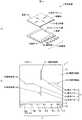
図1(a)は、実施の形態に係る表示装置の分解斜視図であり、(b)は、表示装置の上面図である。図2(a)は、実施の形態に係る表示装置の積層体を基板側から見た下面図であり、(b)は、図1(b)のII(b)-II(b)線で切断した断面を矢印方向から見た断面図であり、(c)は、表示パターンが形成された周辺の断面図の拡大図である。なお、実施の形態に係る各図において、図形間の比率は、実際の比率とは異なる場合がある。[Embodiment]
(Configuration of display device 1)
FIG. 1A is an exploded perspective view of the display device according to the embodiment, and FIG. 1B is a top view of the display device. 2A is a bottom view of the stack of the display device according to the embodiment as viewed from the substrate side, and FIG. 2B is a line II (b) -II (b) in FIG. It is sectional drawing which looked at the cut | disconnected cross section from the arrow direction, (c) is an enlarged view of sectional drawing of the periphery in which the display pattern was formed. In each figure according to the embodiment, the ratio between figures may be different from the actual ratio.
この表示装置1は、一例として、車両に搭載される操作装置の一部を構成するものである。この操作装置は、一例として、車両に搭載されたモニタに表示されたカーソル等を操作できるように構成されている。表示装置1は、例えば、操作装置の操作部に相当する部分に設けられているが、これに限定されない。 As an example, the display device 1 constitutes a part of an operation device mounted on a vehicle. As an example, this operation device is configured to be able to operate a cursor or the like displayed on a monitor mounted on a vehicle. For example, the display device 1 is provided in a portion corresponding to the operation unit of the operation device, but is not limited thereto.
表示装置1は、図1(a)〜(c)、図2(a)及び(b)に示すように、主に、光を出力する光源部10と、光源部10から出力された光が入射する光入射部12と、光入射部12を介して表示される表示パターン14に基づいて光入射部12の第1の面としての裏面122に形成された溝部15と、溝部15を避けるように光入射部12の裏面122に設けられ、表示パターン14の背景を形成する背景部16と、溝部15に設けられ、光入射部12に入射した光の一部を反射させ、背景部16を反射した光の一部によって形成される背景上に表示パターン14を形成する反射部17と、を備えて概略構成されている。 As shown in FIGS. 1A to 1C and FIGS. 2A and 2B, the display device 1 mainly includes a
以下では、光入射部12、背景部16及び反射部17が一体となったものを積層体11と呼ぶものとする。この積層体11の表面は、光入射部12の表面121であり、この表面121の反対の面側には、基板2が設けられている。 Hereinafter, the unit in which the
(基板2の構成)
基板2は、例えば、矩形状に形成されたプリント配線基板である。この基板2の設置面2aには、図1(a)に示すように、矩形状を有するタッチセンサ部200が設けられている。このタッチセンサ部200は、例えば、静電容量方式のタッチセンサを含んで構成されている。タッチセンサ部200は、光入射部12の表面121になされた操作を検出するように構成されている。この基板2には、タッチセンサ部200の一辺に、光源部10が配置されている。(Configuration of substrate 2)
The
(光源部10の構成)
光源部10は、一例として、発光素子10a〜発光素子10fを備えて概略構成されている。この発光素子10a〜発光素子10fは、一例として、発光ダイオード(LED:Light Emitting Diode)である。なお、発光素子の種類及び数は、上記に限定されず、用途に応じて変更可能である。(Configuration of the light source unit 10)
As an example, the
光源部10は、光入射部12の側面である光入射面110から光入射部12の内部に光を出力するように構成されている。具体的には、光源部10の発光素子10a〜発光素子10fは、タッチセンサ部200の一辺に沿うように、予め定められた間隔で並んで配置されている。発光素子10a〜発光素子10fは、その光軸が、実質的に設置面2aの法線と直交するように、また、積層体11の長手方向の側面である光入射面110に向けて光が出力できるように配置されている。 The
発光素子10a〜発光素子10fは、表示装置1に表示させる表示パターン14の色に応じた光を出力するように構成されている。本実施の形態では、一例として、表示パターン14は、白系の色で発光させるため、発光素子10a〜発光素子10fは、白系の光を出力する発光ダイオードを用いて構成されている。 The
(光入射部12の構成)
光入射部12は、光源部10から出力された光を透過する、すなわち、光入射部12の内部に光を伝播させるように構成されている。従って、光入射部12は、一例として、光の外部透過率が高い(およそ90%程度)、MBS(メチルメタクリレートブタジエンスチレン共重合体)樹脂、透明ABS(アクリロニトリルブタジエンスチレン共重合体)樹脂、SBC(スチレンブロック共重合体)樹脂、PC樹脂(ポリカーボネート)及びPET(ポリエチレンテレフタレート)樹脂等を用いて形成される。(Configuration of the light incident portion 12)
The
この光入射部12は、透明な板状の部材である。本実施の形態の光入射部12は、一例として、ポリカーボネート樹脂を用いて形成される。この光入射部12の厚みは、一例として、1mmである。なお、光入射部12の変形例としては、例えば、入射した光が拡散する物質を含んで構成されても良い。 The
また、光入射部12は、例えば、指の滑りを良くするために、表面121にシボ加工が施されている。光入射部12は、表面121にシボ加工が施されているので、シボ加工が施されていない場合と比べて、光を背景部16の方向に反射し易くなっている。さらに、光入射部12は、一例として、帯電防止性及びUV(UltraViolet)吸収性等を有するUVハードコートが施されている。 In addition, the
(表示パターン14の構成)
表示パターン14は、図1(b)に示すように、例えば、表示パターン14a〜表示パターン14dから概略構成されている。この表示パターン14a〜表示パターン14dは、角が丸みを帯びた幅のある細長い線形状を有している。(Configuration of display pattern 14)
As shown in FIG. 1B, the
表示パターン14aは、図1(b)の紙面左に図示された強照明領域140の下方に形成された後述する溝部15aの反射部17に反射した光により主に形成される。表示パターン14bは、この表示パターン14aを図1(b)の紙面において時計回りに90°回転させた位置に形成される。 The display pattern 14a is mainly formed by light reflected on a
表示パターン14bは、図1(b)の紙面上に図示された強照明領域141の下方に形成された後述する溝部15bの反射部17に反射した光により主に形成される。表示パターン14cは、この表示パターン14bを時計回りに90°回転させた位置に形成される。 The display pattern 14b is mainly formed by the light reflected on the
表示パターン14cは、図1(b)の紙面右に図示された強照明領域142の下方に形成された後述する溝部15cの反射部17に反射した光により主に形成される。表示パターン14dは、この表示パターン14cを時計回りに90°回転させた位置に形成される。 The display pattern 14c is mainly formed by the light reflected on the
表示パターン14dは、図1(b)の紙面下に図示された強照明領域143の下方に形成された後述する溝部15dの反射部17に反射した光により主に形成される。表示パターン14aは、この表示パターン14dを時計回りに90°回転させた位置に形成される。つまり、本実施の形態における表示パターン14は、一例として、4つの細長い線が、交わらないように十字に配置されたものである。 The display pattern 14d is mainly formed by the light reflected by the
この光入射部12を介して表示される表示パターン14は、例えば、白系の色を有している。この表示パターン14は、光源部10による照明が行われない状態でも光入射部12を介して視認可能となっている。 The
強照明領域140〜強照明領域143の周囲の弱照明領域145は、表示パターン14の背景であり、強照明領域140〜強照明領域143よりも弱く照明される領域である。この弱照明領域145の色は、背景部16の色が、主に反映されている。 The
具体的には、弱照明領域145は、背景部16を反射した光の一部が、光入射部12から出力することで弱い照明がなされる領域である。また、強照明領域140〜強照明領域143は、溝部15の光入射部12に突出している反射部17を反射した光の一部が、光入射部12から出力することで、弱照明領域145よりも強い照明がなされる領域である。 Specifically, the
(溝部15の構成)
溝部15は、図2(a)〜(c)に示すように、表示パターン14a〜表示パターン14dのそれぞれの下方に形成されている。溝部15は、光入射部12の一部を削り取ったような形状を有している。この溝部15は、例えば、レーザー、切削及び金型等を用いた方法により形成される。本実施の形態では、光入射部12を射出成型により形成する際に、溝部15も形成される。(Configuration of groove 15)
As shown in FIGS. 2A to 2C, the
本実施の形態の溝部15は、表示パターン14a〜表示パターン14dに対応する溝部15a〜溝部15dを備えて概略構成されている。この溝部15a〜溝部15dは、形成される方向以外は、実質的に同じ形状で形成される。よって以下では、主に、溝部15b〜溝部15dの記載に代えて溝部15aについて説明する。また、溝部15a〜溝部15dは、実質的に同じ形状であるので、頂部150、側面151及び側面152は、共通の符号を付すものとする。 The
光入射部12の裏面122から溝部15の頂部150までの距離dは、一例として、図2(c)に示すように、光入射部12の厚みの20%以上40%以下であることが好ましい。この距離dが、10%以下である場合、反射させる光の量が少なくなって表示パターン14が背景よりも強く照明されない可能性があり、50%以上である場合、光源部10より遠い領域に光が到達し難くなり、照明むらが生じる可能性があるからである。 As an example, the distance d from the
本実施の形態の溝部15は、図2(b)及び(c)に示すように、その短手方向の断面が先細りとなる形状(例えばV字形状)を有している。溝部15aを例に取ると、図2(c)に示すように、溝部15aの側面151と光入射部12の裏面122との角度θ1、及び側面152と裏面122との角度θ2が、実質的に等しくなるように形成されている。また、溝部15b〜溝部15dは、溝部15aと同様に、それぞれの角度θ1及び角度θ2が実質的に等しい。なお、溝部15は、先細りとなる形状に限定されず、光入射部12内を伝播する光を上方に向けて反射可能な形状であれば、形成方法等に応じて形状は変更可能である。As shown in FIGS. 2B and 2C, the
(背景部16の構成)
背景部16は、例えば、印刷によって、光入射部12の裏面122に形成される。ただし、背景部16は、溝部15を埋めるようには形成されない。この印刷は、例えば、スクリーン印刷法及びインクジェット印刷法等の印刷法を用いて行われる。また、印刷に用いられるインクは、上記の印刷法と、背景の色等に応じて選択される。この背景部16の厚みは、一例として、8μmである。(Configuration of the background portion 16)
The
この背景部16は、例えば、光が透過しない黒系の色のインクを用いて形成されている。従って、弱照明領域145は、例えば、黒色の背景が間接的に照明されたように見える。つまり、光入射部12の内部を反射しながら伝播する光100は、その一部が、光入射部12と背景部16との実質的な境界面となる裏面122において光102として反射して弱照明領域145から出力される。 The
(反射部17の構成)
反射部17は、溝部15が形成された後の背景部16の裏面160に形成される。反射部17は、例えば、スクリーン印刷法及びインクジェット印刷法等の印刷法を用いて形成される。また、印刷に用いられるインクは、上記の印刷法と、表示パターン14の色等に応じて選択される。この反射部17の厚みは、一例として、20μmである。(Structure of the reflection part 17)
The
反射部17は、図2(b)及び(c)に示すように、溝部15の内部にも形成される。反射部17は、その一部が光入射部12の内部に形成される。従って、光入射部12の内部を反射しながら伝播する光は、光入射部12に突出した溝部15の側面151又は側面152によって反射され、その一部が、溝部15に対応した強照明領域から出力される。なお、反射部17は、溝部15のみに設けられても良い。 The
溝部15aにおいて、光入射部12の内部を反射しながら伝播する光100は、例えば、図2(c)に示すように、側面151又は側面152により反射された光101となって、その一部が強照明領域140から光103として出力される。溝部15は、光入射部12の内部に設けられるので、光入射部12の裏面122で反射する光と比べて、より多くの光100を上方に反射させることが可能となる。従って、溝部15は、光入射部12の表面121において、単位面積当たりの光束、すなわち輝度を高くして強照明領域140〜強照明領域143、つまり表示パターン14を形成することが可能となる。 In the
以下に、本実施の形態に係る表示装置1の照明について説明する。 Below, the illumination of the display apparatus 1 which concerns on this Embodiment is demonstrated.
(表示装置1の照明について)
表示装置1は、図2(b)に示すように、駆動に必要な電力が供給された後、光源部10が光100を出力する。(About illumination of the display device 1)
In the display device 1, as shown in FIG. 2B, the
光源部10から出力された光100は、主に、積層体11の光入射面110から光入射部12内に伝播する。 The light 100 output from the
光入射部12を伝播する光100の一部は、大気と光入射部12の実質的な境界面となる表面121、及び光入射部12と背景部16の実質的な境界面となる裏面122において、反射を繰り返しながら伝播する。この反射を繰り返しながら伝播する光100の一部が、弱照明領域145から光102として出力する。 A part of the light 100 propagating through the
また、溝部15の周辺に到達した光101の一部は、溝部15の側面151や側面152により反射する。反射した光101の一部は、反射した溝部15a〜溝部15dに応じた強照明領域140〜強照明領域143から光103として出力される。この溝部15を反射して出力された光103は、背景部16で反射して出力された光102よりも単位面積当たりの光束が多い。 Further, a part of the light 101 that reaches the periphery of the
従って、弱照明領域145が、間接的な照明で弱く照明される。また、強照明領域140〜強照明領域143は、間接的な照明でありながら弱照明領域145よりも強く照明されると共に、表示パターン14を形成する溝部15が立体的であることから、奥行き感や立体感のある表示となる。 Therefore, the
以下に、表示装置1の作製工程の一例を示す。 Below, an example of the manufacturing process of the display apparatus 1 is shown.
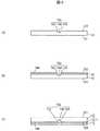
(表示装置1の作製工程)
図3(a)〜(c)は、実施の形態に係る表示装置の製造工程を示す要部断面部である。図3(a)〜(c)は、表示装置1の製造工程を、図1(b)のII(b)-II(b)で切断した断面を要部断面として示している。(Manufacturing process of display device 1)
FIGS. 3A to 3C are cross-sectional views showing the main parts of the manufacturing process of the display device according to the embodiment. FIGS. 3A to 3C show a cross section of the manufacturing process of the display device 1 taken along II (b) -II (b) in FIG.
まず、図3(a)に示すように、射出成型により、溝部15a〜溝部15dが形成された光入射部12を形成する。 First, as shown in FIG. 3A, the
次に、図3(b)に示すように、印刷により背景部16を形成する。この背景部16は、溝部15a〜溝部15dを避けるように形成される。 Next, as shown in FIG. 3B, the
次に、図3(c)に示すように、背景部16の裏面160に、印刷により反射部17を形成し、基板2に設置して表示装置1を得る。この反射部17は、溝部15a〜溝部15dの内部にも形成される。 Next, as shown in FIG. 3C, the
(実施の形態の効果)
本実施の形態に係る表示装置1は、奥行き感や立体感のある優れた意匠を備えることができる。具体的には、この表示装置1は、背景(弱照明領域145)が間接的に照明されると共に、立体的に形成された反射部17により反射された光に基づいて表示パターン14が形成されるので、間接的な照明でありながら表示パターン14が背景よりも強く照明され、奥行き感や立体感のある優れた意匠を備えることができる。(Effect of embodiment)
The display device 1 according to the present embodiment can be provided with an excellent design having a sense of depth and a stereoscopic effect. Specifically, in the display device 1, the background (weak illumination area 145) is indirectly illuminated, and the
この表示装置1は、溝部15が光入射部12に設けられることから、光入射部12の裏面122で反射する光と比べて、より多くの光を上方に反射させることができるので、弱照明領域145よりも輝度が高い強照明領域140〜強照明領域143、すなわち表示パターン14を形成することができる。 Since this display device 1 is provided with the
この表示装置1は、溝部15の側面151と光入射部12の裏面122との角度θ1、及び側面152と裏面122との角度θ2が、実質的に等しくなるように形成されているので、溝部15の形成が容易となり、製造コストが抑制される。The display device 1 is formed so that the angle θ1 between the
この表示装置1は、奥行き感や立体感のある意匠を表現するための構成が簡単であるので、照明の角度等を調整することで奥行き感等を演出するものと比べて、製造コストを抑制することができる。 Since this display device 1 has a simple configuration for expressing a design with a sense of depth or a three-dimensional effect, the manufacturing cost can be reduced compared to a device that produces a sense of depth by adjusting the angle of illumination or the like. can do.
この表示装置1は、積層体11の側面に光源部10が配置されるので、表示パターンの下方から照明する場合と比べて、間接的な照明の効果が得られる。また表示装置1は、側面から光を入射するにも関わらず、強照明領域140〜強照明領域143、及び弱照明領域145を形成することができるので、表示に変化が生まれ意匠に優れている。 In the display device 1, since the
以下に、実施の形態の溝部の変形例1〜変形例3について記載する。 Below, it describes about the modification 1-the modification 3 of the groove part of embodiment.
(変形例)
図4(a)〜(c)は、実施の形態の変形例1〜変形例3を示す要部断面図である。以下に示す変形例1〜変形例3において、実施の形態と同じ機能及び構成を有する部分には、実施の形態と同じ符号を付し、その説明は省略するものとする。(Modification)
FIGS. 4A to 4C are cross-sectional views of main parts showing Modification Examples 1 to 3 of the embodiment. In the following modified examples 1 to 3, parts having the same functions and configurations as those of the embodiment are denoted by the same reference numerals as those of the embodiment, and description thereof is omitted.
変形例1は、図4(a)に示すように、溝部15の形状が、先細りの形状ではなく実質的に同一の幅で形成された凹形状となっている。なお、図4(a)では、溝部15の例として溝部15aが図示されているが、溝部15b〜溝部15dは、実質的に同じ形状を有している。 In Modification 1, as shown in FIG. 4A, the shape of the
具体的には、変形例1の表示装置1は、実質的に同じ幅で形成された凹形状の溝部15を備えている。変形例1の溝部15は、光入射部12の裏面122に対して側面153及び側面154がほぼ直角となるように形成されている。変形例1の溝部15の上面155から光入射部12の裏面122までの距離は、実施の形態に記載の距離dと同様の範囲で形成されるがこれに限定されない。 Specifically, the display device 1 of Modification 1 includes a
この変形例1の場合、光入射部12を伝播する光の一部は、反射を繰り返しながら側面153、側面154及び上面155で反射する。その反射する光の中で、主に、上面155で反射した光の一部が、光入射部12から出力され、強照明領域140〜強照明領域143、すなわち表示パターン14が形成される。 In the case of the first modification, a part of the light propagating through the
変形例2は、図4(b)に示すように、溝部15の側面156と側面157の角度θ3及び角度θ4が異なっている。この角度θ3とは、側面156と裏面122とがなす角度であり、角度θ4とは、側面157と裏面122とがなす角度である。In
具体的には、変形例2の表示装置1は、光源部10の光軸と交差する方向に延びる溝部15、つまり溝部15a及び溝部15cに、角度が異なる側面156及び側面157が形成される。この溝部15a及び溝部15cは、光源部10に近い方の側面156の角度θ3が、反対側である側面157の角度θ4よりも大きくなるように構成されている。他の溝部15b及び溝部15cは、例えば、側面の角度が実質的に同じで良い。従って、図4(b)では、溝部15aが図示されているが、溝部15cは、実質的に同じ形状を有している。Specifically, in the display device 1 of the second modification, the side surface 156 and the side surface 157 having different angles are formed in the
図4(b)に示す、光源部10側の光入射面110から側面156までの第1の領域105は、溝部15の配置によっては、例えば、光入射面110の反対側の端面111から側面157までの第2の領域106よりも入射した光が多く存在すると考えられる。言い換えるなら、光入射部12の内部を伝播する光は、溝部15a及び溝部15cに遮られて、第2の領域106に伝播し難いことが考えられる。 4B, the first region 105 from the
従って、第1の領域105と第2の領域106との照明むらを抑制するため、角度θ3は、角度θ4よりも大きいことが好ましい。また溝部15の頂部158から光入射部12の裏面122までの距離は、一例として、実施の形態に記載の距離dと同様の範囲で形成される。Therefore, in order to suppress uneven illumination between the first region 105 and the
変形例3は、図4(c)に示すように、溝部15が半円形状の溝となっている。変形例3の溝部15の側面159の頂部から光入射部12の裏面122までの距離は、実施の形態に記載の距離dと同様の範囲で形成される。側面159で反射した光の一部は、光入射部12から出力され、強照明領域140〜強照明領域143、すなわち表示パターン14が形成される。 In Modification 3, as shown in FIG. 4C, the
なお、他の変形例として、表示装置1は、光入射面110以外の側面に、光を反射する反射部材を設けても良い。この表示装置1は、光入射面110以外の側面に到達した光が反射されるので、背景や表示パターン14の照明むらが抑制される。また、溝部15の裏側の凹部に樹脂を埋めて静電の感度を上げる構成としてもよい。 As another modification, the display device 1 may be provided with a reflecting member that reflects light on a side surface other than the
以上、本発明のいくつかの実施の形態及び変形例を説明したが、これらの実施の形態及び変形例は、一例に過ぎず、特許請求の範囲に係る発明を限定するものではない。これら新規な実施の形態及び変形例は、その他の様々な形態で実施されることが可能であり、本発明の要旨を逸脱しない範囲で、種々の省略、置き換え、変更等を行うことができる。また、これら実施の形態及び変形例の中で説明した特徴の組合せの全てが発明の課題を解決するための手段に必須であるとは限らない。さらに、これら実施の形態及び変形例は、発明の範囲及び要旨に含まれるとともに、特許請求の範囲に記載された発明とその均等の範囲に含まれる。 As mentioned above, although some embodiment and modification of this invention were demonstrated, these embodiment and modification are only examples, and do not limit the invention based on a claim. These novel embodiments and modifications can be implemented in various other forms, and various omissions, replacements, changes, and the like can be made without departing from the scope of the present invention. In addition, not all combinations of features described in these embodiments and modifications are necessarily essential to the means for solving the problems of the invention. Furthermore, these embodiments and modifications are included in the scope and gist of the invention, and are included in the invention described in the claims and the equivalents thereof.
1…表示装置
2…基板
2a…設置面
10…光源部
10a〜10f…発光素子
11…積層体
12…光入射部
14,14a〜14d…表示パターン
15…背景部
16,16a〜16d…溝部
17…反射部
100〜103…光
105…第1の領域
106…第2の領域
110…光入射面
111…端面
121…第1の面
122…第2の面
140〜143…強照明領域
145…弱照明領域
150…第3の面
160…頂部
161〜164…側面
165…上面
166,167…側面
168…頂部
169…側面
200…タッチセンサ部DESCRIPTION OF SYMBOLS 1 ...
Claims (3)
Translated fromJapanese前記光源部から出力された光が入射する光入射面を側面に有する光入射部と、
前記光入射部を介して表示される表示パターンに基づいて前記光入射部の裏面に形成された溝部と、
前記溝部を避けるように前記光入射部の前記裏面に設けられ、前記表示パターンの背景を形成する背景部と、
前記溝部に設けられ、前記光入射部に入射した光の一部を反射させ、前記背景部を反射した光の一部によって形成される前記背景上に前記表示パターンを形成する反射部と、
を備え、
前記光入射部は、入射した光の一部を前記背景部の方向に反射するシボを表面に有する表示装置。A light source unit that outputs light;
A light incident portionhaving a light incident surface side of light output from thefront Symbol source unit is incident,
A groove portion formed on theback surface of the light incident part on the basis of the display pattern displayed via the light incident portion,
Wherein provided on theback surface of the light entrance portion so as to avoid the groove, and the background portion that forms the background of the display pattern,
A reflective part that is provided in the groove part, reflects a part of the light incident on the light incident part, and forms the display pattern on the background formed by a part of the light reflected on the background part;
Equipped witha,
The light incident part is a display devicehaving on the surface a texture that reflects a part of incident light in the direction of the background part .
前記溝部に設けられた前記反射部を反射した光の一部が、前記光入射部から出力することで、前記弱照明領域よりも強い照明がなされる強照明領域を形成する請求項1に記載の表示装置。A part of the light reflected from the background part forms a weak illumination area where weak illumination is performed by outputting from the light incident part,
2. The strong illumination region in which a part of the light reflected by the reflection portion provided in the groove portion is output from the light incident portion to be more strongly illuminated than the weak illumination region is formed. Display device.
前記基板に設けられ、前記光入射部の前記表面になされた操作を検出するタッチセンサ部と、
を備え、
前記溝部に樹脂が埋め込まれた請求項1又は2に記載の表示装置。Further, a substrate provided with the light source unit,
Provided on the substrate, a touch sensor section which detects an operation performed onthe surface of the light incident portion,
With
The display device according to claim 1, wherein a resin is embedded in the groove.
Priority Applications (4)
| Application Number | Priority Date | Filing Date | Title |
|---|---|---|---|
| JP2013058675AJP5937032B2 (en) | 2013-03-21 | 2013-03-21 | Display device |
| CN201410095194.8ACN104064114A (en) | 2013-03-21 | 2014-03-14 | Display device |
| EP14160478.5AEP2782089A3 (en) | 2013-03-21 | 2014-03-18 | Display device |
| US14/218,259US20140286051A1 (en) | 2013-03-21 | 2014-03-18 | Display device |
Applications Claiming Priority (1)
| Application Number | Priority Date | Filing Date | Title |
|---|---|---|---|
| JP2013058675AJP5937032B2 (en) | 2013-03-21 | 2013-03-21 | Display device |
Publications (2)
| Publication Number | Publication Date |
|---|---|
| JP2014182356A JP2014182356A (en) | 2014-09-29 |
| JP5937032B2true JP5937032B2 (en) | 2016-06-22 |
Family
ID=50473013
Family Applications (1)
| Application Number | Title | Priority Date | Filing Date |
|---|---|---|---|
| JP2013058675AExpired - Fee RelatedJP5937032B2 (en) | 2013-03-21 | 2013-03-21 | Display device |
Country Status (4)
| Country | Link |
|---|---|
| US (1) | US20140286051A1 (en) |
| EP (1) | EP2782089A3 (en) |
| JP (1) | JP5937032B2 (en) |
| CN (1) | CN104064114A (en) |
Families Citing this family (1)
| Publication number | Priority date | Publication date | Assignee | Title |
|---|---|---|---|---|
| JP6009644B1 (en)* | 2015-11-30 | 2016-10-19 | 株式会社東海理化電機製作所 | Panel and touchpad |
Family Cites Families (27)
| Publication number | Priority date | Publication date | Assignee | Title |
|---|---|---|---|---|
| US1931742A (en)* | 1930-12-24 | 1933-10-24 | Paul J Scharringhausen | Illuminated sign |
| US1816220A (en)* | 1931-04-06 | 1931-07-28 | Hotchner Fred | Changeable luminous display |
| US4252416A (en)* | 1978-10-23 | 1981-02-24 | Societe Suisse Pour L'industrie Horlogere Management Services S.A. | Optical instrument for gathering and distribution of light |
| JPH0348628Y2 (en)* | 1986-06-16 | 1991-10-17 | ||
| JPS6341891A (en)* | 1986-08-07 | 1988-02-23 | 下総 忠敬 | Stereo display |
| JPH01101287U (en)* | 1987-12-25 | 1989-07-07 | ||
| JPH0684486U (en)* | 1993-05-11 | 1994-12-02 | 株式会社不二工 | Surface emitter |
| JP3187280B2 (en)* | 1995-05-23 | 2001-07-11 | シャープ株式会社 | Surface lighting device |
| US7108414B2 (en)* | 1995-06-27 | 2006-09-19 | Solid State Opto Limited | Light emitting panel assemblies |
| JPH1010980A (en)* | 1996-06-21 | 1998-01-16 | Seikei Giken:Kk | Display member |
| JPH09138661A (en) | 1996-08-29 | 1997-05-27 | Yazaki Corp | Display device |
| US6386721B1 (en)* | 1999-07-08 | 2002-05-14 | Physical Optics Corporation | Light pipe having one or more integral diffusers |
| US6471388B1 (en)* | 1999-12-30 | 2002-10-29 | Bji Energy Solutions Llc | Illumination apparatus for edge lit signs and display |
| US6565225B2 (en)* | 2000-07-19 | 2003-05-20 | Sanyo Electric Co., Ltd. | Bar-shaped light guide, beam lighting device using the bar-shaped light guide, and surface lighting device using the beam lighting device |
| JP2002198567A (en)* | 2000-12-25 | 2002-07-12 | Hitachi Ltd | Display device and portable information device using the same |
| US20040070965A1 (en)* | 2002-10-10 | 2004-04-15 | Bin-Tzer Lin | Removable light guide system for advertising display |
| CN2577702Y (en)* | 2002-11-19 | 2003-10-08 | 上海富申冷机有限公司 | Decorative lamp housing of commercial refrigerator |
| JP5177729B2 (en)* | 2005-03-30 | 2013-04-10 | シチズンホールディングス株式会社 | Instrument display board and method for manufacturing instrument display board |
| EP1922574B1 (en)* | 2005-08-31 | 2018-10-10 | Universal Avionics Systems Corporation | Led backlight for flat panel display |
| JP2008010291A (en)* | 2006-06-29 | 2008-01-17 | Citizen Electronics Co Ltd | Light guide plate, back light unit, and display device equipped with its back light unit |
| JP5000423B2 (en)* | 2007-08-09 | 2012-08-15 | ローム株式会社 | Still image display device |
| JP2009204885A (en)* | 2008-02-28 | 2009-09-10 | Omron Corp | Display device |
| CN101616269B (en)* | 2008-06-27 | 2012-11-28 | 新奥特(北京)视频技术有限公司 | Method for generating shadow caption based on structure of characters |
| US20110047840A1 (en)* | 2009-09-01 | 2011-03-03 | Ou Seok S | Led display apparatus |
| US8382324B2 (en)* | 2010-04-29 | 2013-02-26 | Southern Taiwan University | Radiation structure without light guiding board |
| JP5533595B2 (en)* | 2010-11-25 | 2014-06-25 | 株式会社デンソー | Vehicle instrument |
| TWI572947B (en)* | 2010-11-30 | 2017-03-01 | 康寧公司 | Display device with light diffusive glass panel |
- 2013
- 2013-03-21JPJP2013058675Apatent/JP5937032B2/ennot_activeExpired - Fee Related
- 2014
- 2014-03-14CNCN201410095194.8Apatent/CN104064114A/enactivePending
- 2014-03-18EPEP14160478.5Apatent/EP2782089A3/ennot_activeWithdrawn
- 2014-03-18USUS14/218,259patent/US20140286051A1/ennot_activeAbandoned
Also Published As
| Publication number | Publication date |
|---|---|
| US20140286051A1 (en) | 2014-09-25 |
| EP2782089A2 (en) | 2014-09-24 |
| CN104064114A (en) | 2014-09-24 |
| JP2014182356A (en) | 2014-09-29 |
| EP2782089A3 (en) | 2014-10-15 |
Similar Documents
| Publication | Publication Date | Title |
|---|---|---|
| US10288800B1 (en) | Multilayer structure with embedded light source and light-guiding features and related method of manufacture | |
| CN108291695A (en) | Lighting device and car light including the lighting device | |
| JP6244904B2 (en) | Light guide, light emitting device and game machine | |
| JP6389488B2 (en) | Operation device | |
| CN102737559A (en) | Light display device for depicting three-dimensional object | |
| CN107329244A (en) | infinite mirror | |
| JP6029170B2 (en) | Decorative panel | |
| JP5937032B2 (en) | Display device | |
| JP2018155819A (en) | Display device | |
| JP3225417U (en) | Light guide decoration plate and lighting module | |
| JP2020041851A (en) | Resin decorative component and dial plate | |
| JP2014182355A (en) | Display device | |
| JP5247269B2 (en) | Game machine | |
| KR102818808B1 (en) | Lighting device | |
| JP2014182357A (en) | Display device | |
| US9720457B1 (en) | Solid state disk | |
| JP6543052B2 (en) | Stereoscopic structure, touch sensor with design, touch panel and electronic device | |
| JP2011171059A (en) | Switch module | |
| JP2018181623A (en) | Vehicular lighting fixture | |
| JP2013062165A (en) | Light guide and light guide unit having the same | |
| JP2013200442A (en) | Display device | |
| CN205656365U (en) | Infinite mirror | |
| CN103443671A (en) | Mosaic lighting device with transparent body with a plurality of light guides delimited by slits | |
| KR101173609B1 (en) | Indicator using light guide plate | |
| JP6135983B2 (en) | Laminated molded body of resin and laminated molded product |
Legal Events
| Date | Code | Title | Description |
|---|---|---|---|
| A977 | Report on retrieval | Free format text:JAPANESE INTERMEDIATE CODE: A971007 Effective date:20150206 | |
| A131 | Notification of reasons for refusal | Free format text:JAPANESE INTERMEDIATE CODE: A131 Effective date:20150217 | |
| A521 | Request for written amendment filed | Free format text:JAPANESE INTERMEDIATE CODE: A523 Effective date:20150323 | |
| A131 | Notification of reasons for refusal | Free format text:JAPANESE INTERMEDIATE CODE: A131 Effective date:20151104 | |
| A521 | Request for written amendment filed | Free format text:JAPANESE INTERMEDIATE CODE: A523 Effective date:20151214 | |
| TRDD | Decision of grant or rejection written | ||
| A01 | Written decision to grant a patent or to grant a registration (utility model) | Free format text:JAPANESE INTERMEDIATE CODE: A01 Effective date:20160426 | |
| A61 | First payment of annual fees (during grant procedure) | Free format text:JAPANESE INTERMEDIATE CODE: A61 Effective date:20160511 | |
| R150 | Certificate of patent or registration of utility model | Ref document number:5937032 Country of ref document:JP Free format text:JAPANESE INTERMEDIATE CODE: R150 | |
| LAPS | Cancellation because of no payment of annual fees |