Movatterモバイル変換


[0]ホーム

URL:


JP5936850B2 - Ultrasonic diagnostic apparatus and image processing apparatus - Google Patents

Ultrasonic diagnostic apparatus and image processing apparatus
Download PDF

Info

Publication number
JP5936850B2
JP5936850B2JP2011256391AJP2011256391AJP5936850B2JP 5936850 B2JP5936850 B2JP 5936850B2JP 2011256391 AJP2011256391 AJP 2011256391AJP 2011256391 AJP2011256391 AJP 2011256391AJP 5936850 B2JP5936850 B2JP 5936850B2
Authority
JP
Japan
Prior art keywords
image
unit
lumen
ultrasonic diagnostic
diagnostic apparatus
Prior art date
Legal status (The legal status is an assumption and is not a legal conclusion. Google has not performed a legal analysis and makes no representation as to the accuracy of the status listed.)
Active
Application number
JP2011256391A
Other languages
Japanese (ja)
Other versions
JP2013106903A (en
JP2013106903A5 (en
Inventor
嶺 喜隆
喜隆 嶺
Current Assignee (The listed assignees may be inaccurate. Google has not performed a legal analysis and makes no representation or warranty as to the accuracy of the list.)
Toshiba Corp
Canon Medical Systems Corp
Original Assignee
Toshiba Corp
Toshiba Medical Systems Corp
Priority date (The priority date is an assumption and is not a legal conclusion. Google has not performed a legal analysis and makes no representation as to the accuracy of the date listed.)
Filing date
Publication date
Application filed by Toshiba Corp, Toshiba Medical Systems CorpfiledCriticalToshiba Corp
Priority to JP2011256391ApriorityCriticalpatent/JP5936850B2/en
Publication of JP2013106903ApublicationCriticalpatent/JP2013106903A/en
Publication of JP2013106903A5publicationCriticalpatent/JP2013106903A5/ja
Application grantedgrantedCritical
Publication of JP5936850B2publicationCriticalpatent/JP5936850B2/en
Activelegal-statusCriticalCurrent
Anticipated expirationlegal-statusCritical

Links

Images

Landscapes

Description

Translated fromJapanese

本発明の実施の形態は、超音波診断装置及び画像処理装置に関する。  Embodiments described herein relate generally to an ultrasonic diagnostic apparatus and an image processing apparatus.

従来、超音波診断装置は、X線診断装置やX線コンピュータ断層撮影装置などの他の医用画像診断装置に比べ、簡便な操作性、被爆のおそれがない非侵襲性などの利点を備えた装置として、今日の医療において、心臓、肝臓、腎臓、乳腺など、様々な生体組織の検査や診断に利用されている。  2. Description of the Related Art Conventionally, an ultrasonic diagnostic apparatus is an apparatus having advantages such as simple operability and non-invasiveness that does not cause exposure, compared to other medical image diagnostic apparatuses such as an X-ray diagnostic apparatus and an X-ray computed tomography apparatus. In today's medical care, it is used for examination and diagnosis of various living tissues such as heart, liver, kidney and mammary gland.

近年、超音波診断装置においては、2Dアレイプローブ(two dimensional array probe)や、メカニカル4Dプローブ(mechanical four dimensional probe)を用いて3次元データ(ボリュームデータ)を収集し、収集したボリュームデータを用いて消化管や血管などの管腔内の観察が行われている。例えば、収集したボリュームデータから管腔が描出された直交3断面のMPR(Multi Planar Reconstruction)画像を生成して表示させたり、輝度値を白黒反転させるcavityモードにより管腔を立体表示させたりすることで、管腔内の観察が行われる。しかしながら、上述した従来の技術では、管腔内を簡便に観察することが困難となる場合があった。  In recent years, in an ultrasonic diagnostic apparatus, 3D data (volume data) is collected using a 2D array probe (two dimensional array probe) or a mechanical 4D probe (mechanical four dimensional probe), and the collected volume data is used. Observations in the lumen of the digestive tract and blood vessels are performed. For example, an MPR (Multi Planar Reconstruction) image with three orthogonal cross-sections depicting the lumen from the collected volume data is generated and displayed, or the lumen is stereoscopically displayed in a cavity mode in which the luminance value is reversed in black and white. Thus, observation within the lumen is performed. However, with the conventional technology described above, it may be difficult to simply observe the inside of the lumen.

特開2010−200821号公報JP 2010-200241 A

本発明が解決しようとする課題は、管腔内を簡便に観察することができる超音波診断装置及び画像処理装置を提供することである。  The problem to be solved by the present invention is to provide an ultrasonic diagnostic apparatus and an image processing apparatus that can easily observe the inside of a lumen.

実施の形態の超音波診断装置は、設定手段と、生成手段と、表示制御手段とを備える。設定手段は、検体に対する3次元的な超音波走査により収集された3次元画像データに含まれる管腔に芯線を設定する。生成手段は、前記設定手段によって設定された芯線に沿ったカーブドMPR画像を、前記3次元画像データを用いて生成する。表示制御手段は、前記生成手段によって生成された前記カーブドMPR画像、および前記芯線上の視点からの仮想内視鏡画像を所定の表示部にて表示させ、前記視点の情報を前記カーブドMPR画像上に表示させる。The ultrasonic diagnostic apparatus according to the embodiment includes a setting unit, a generation unit, and a display control unit. Setting means sets the core wire to the lumen included in the three-dimensional image data collectedby thethree-dimensional ultrasound scanagainst thesubject. The generation unit generatesa curved MPR imagealong the coreline set by the setting unitusing the three-dimensional image data. The display control means displays thecurved MPR image generated by the generating meansand the virtual endoscopic image from the viewpoint on the core line on a predetermined display unit, and the viewpoint information is displayed on thecurved MPR image. Ruto be displayed on.

図1は、第1の実施形態に係る超音波診断装置の全体構成を説明するための図である。FIG. 1 is a diagram for explaining the overall configuration of the ultrasonic diagnostic apparatus according to the first embodiment.図2は、第1の実施形態に係る画像生成部の概要を説明するための図である。FIG. 2 is a diagram for explaining the outline of the image generation unit according to the first embodiment.図3は、従来技術における課題を説明するための図である。FIG. 3 is a diagram for explaining a problem in the prior art.図4は、第1の実施形態に係る画像生成部の構成の一例を示す図である。FIG. 4 is a diagram illustrating an example of the configuration of the image generation unit according to the first embodiment.図5は、第1の実施形態に係るトレースライン設定部による処理の一例を説明するための図である。FIG. 5 is a diagram for explaining an example of processing by the trace line setting unit according to the first embodiment.図6は、第1の実施形態に係るカーブドMPR画像生成部による第1の処理を説明するための図である。FIG. 6 is a diagram for explaining the first processing by the curved MPR image generation unit according to the first embodiment.図7は、第1の実施形態に係るカーブドMPR画像生成部による第2の処理を説明するための図である。FIG. 7 is a diagram for explaining the second processing by the curved MPR image generation unit according to the first embodiment.図8Aは、第1の実施形態に係る仮想内視鏡画像生成部による処理の一例を説明するための図である。FIG. 8A is a diagram for explaining an example of processing by the virtual endoscopic image generation unit according to the first embodiment.図8Bは、第1の実施形態に係る仮想内視鏡画像生成部によって生成された仮想内視鏡画像の従来の表示例を示す図である。FIG. 8B is a diagram illustrating a conventional display example of the virtual endoscopic image generated by the virtual endoscopic image generating unit according to the first embodiment.図9Aは、第1の実施形態に係る制御部によるカーブドMPR画像の第1の表示例を示す図である。FIG. 9A is a diagram illustrating a first display example of the curved MPR image by the control unit according to the first embodiment.図9Bは、第1の実施形態に係る制御部によるカーブドMPR画像の第2の表示例を示す図である。FIG. 9B is a diagram illustrating a second display example of the curved MPR image by the control unit according to the first embodiment.図10は、第1の実施形態に係る超音波診断装置による処理の手順を示すフローチャートである。FIG. 10 is a flowchart illustrating a processing procedure performed by the ultrasonic diagnostic apparatus according to the first embodiment.図11は、第2の実施形態に係る画像生成部の構成の一例を示す図である。FIG. 11 is a diagram illustrating an example of a configuration of an image generation unit according to the second embodiment.図12は、第2の実施形態に係る連結ボリュームデータ生成部による処理の一例を説明するための図である。FIG. 12 is a diagram for explaining an example of processing by the linked volume data generation unit according to the second embodiment.図13は、第2の実施形態に係るカーブドMPR画像生成部による処理の一例を説明するための図である。FIG. 13 is a diagram for explaining an example of processing by the curved MPR image generation unit according to the second embodiment.図14は、第2の実施形態に係る超音波診断装置による処理の手順を示すフローチャートである。FIG. 14 is a flowchart illustrating a processing procedure performed by the ultrasonic diagnostic apparatus according to the second embodiment.図15は、第3の実施形態に係る第1の表示例を示す図である。FIG. 15 is a diagram illustrating a first display example according to the third embodiment.図16は、第3の実施形態に係る第2の表示例を示す図である。FIG. 16 is a diagram illustrating a second display example according to the third embodiment.図17は、第3の実施形態に係る第3の表示例を示す図である。FIG. 17 is a diagram illustrating a third display example according to the third embodiment.図18は、第3の実施形態に係るカーブドMPR画像生成の一例を説明するための図である。FIG. 18 is a diagram for explaining an example of curved MPR image generation according to the third embodiment.

(第1の実施形態)
まず、本実施形態に係る超音波診断装置の構成について説明する。図1は、本実施形態に係る超音波診断装置100の構成を説明するための図である。図1に示すように、第1の実施形態に係る超音波診断装置100は、超音波プローブ1と、モニタ2と、入力装置3と、装置本体10とを有する。また、装置本体10は、ネットワーク200を介して外部装置4と接続される。
(First embodiment)
First, the configuration of the ultrasonic diagnostic apparatus according to the present embodiment will be described. FIG. 1 is a diagram for explaining a configuration of an ultrasonicdiagnostic apparatus 100 according to the present embodiment. As shown in FIG. 1, the ultrasonicdiagnostic apparatus 100 according to the first embodiment includes anultrasonic probe 1, amonitor 2, aninput apparatus 3, and an apparatusmain body 10. Theapparatus body 10 is connected to the external apparatus 4 via thenetwork 200.

超音波プローブ1は、複数の圧電振動子を有し、これら複数の圧電振動子は、後述する装置本体10が有する送受信部11から供給される駆動信号に基づき超音波を発生する。また、超音波プローブ1は、被検体Pからの反射波を受信して電気信号に変換する。また、超音波プローブ1は、圧電振動子に設けられる整合層と、圧電振動子から後方への超音波の伝播を防止するバッキング材などを有する。なお、超音波プローブ1は、装置本体10と着脱自在に接続される。  Theultrasonic probe 1 includes a plurality of piezoelectric vibrators, and the plurality of piezoelectric vibrators generate ultrasonic waves based on a drive signal supplied from a transmission / reception unit 11 included in the apparatusmain body 10 described later. Theultrasonic probe 1 receives a reflected wave from the subject P and converts it into an electrical signal. Theultrasonic probe 1 includes a matching layer provided on the piezoelectric vibrator, a backing material that prevents propagation of ultrasonic waves from the piezoelectric vibrator to the rear, and the like. Theultrasonic probe 1 is detachably connected to the apparatusmain body 10.

超音波プローブ1から被検体Pに超音波が送信されると、送信された超音波は、被検体Pの体内組織における音響インピーダンスの不連続面で次々と反射され、反射波信号として超音波プローブ1が有する複数の圧電振動子にて受信される。受信される反射波信号の振幅は、超音波が反射される不連続面における音響インピーダンスの差に依存する。なお、送信された超音波パルスが、移動している血流や心臓壁などの表面で反射された場合の反射波信号は、ドプラ効果により、移動体の超音波送信方向に対する速度成分に依存して、周波数偏移を受ける。  When ultrasonic waves are transmitted from theultrasonic probe 1 to the subject P, the transmitted ultrasonic waves are reflected one after another at the discontinuous surface of the acoustic impedance in the body tissue of the subject P, and the ultrasonic probe is used as a reflected wave signal. 1 is received by a plurality of piezoelectric vibrators. The amplitude of the received reflected wave signal depends on the difference in acoustic impedance at the discontinuous surface where the ultrasonic wave is reflected. Note that the reflected wave signal when the transmitted ultrasonic pulse is reflected on the moving blood flow or the surface of the heart wall depends on the velocity component of the moving body in the ultrasonic transmission direction due to the Doppler effect. And undergoes a frequency shift.

ここで、本実施形態に係る超音波プローブ1は、超音波により被検体Pを2次元で走査するとともに、被検体Pを3次元で走査することが可能な超音波プローブである。具体的には、本実施形態に係る超音波プローブ1は、被検体Pを2次元で走査する複数の超音波振動子を所定の角度(揺動角度)で揺動させることで、被検体Pを3次元で走査するメカニカルスキャンプローブである。  Here, theultrasound probe 1 according to the present embodiment is an ultrasound probe capable of scanning the subject P in two dimensions with ultrasound and scanning the subject P in three dimensions. Specifically, theultrasonic probe 1 according to the present embodiment swings a plurality of ultrasonic transducers that scan the subject P in two dimensions at a predetermined angle (swing angle), so that the subject P Is a mechanical scan probe that scans in three dimensions.

なお、本実施形態は、超音波プローブ1が、複数の超音波振動子がマトリックス状に配置されることで、被検体Pを3次元で超音波走査することが可能な2次元超音波プローブである場合であっても適用可能である。2次元超音波プローブは、超音波を集束して送信することで、被検体Pを2次元で走査することが可能である。  In this embodiment, theultrasonic probe 1 is a two-dimensional ultrasonic probe that can ultrasonically scan the subject P in three dimensions by arranging a plurality of ultrasonic transducers in a matrix. Even in some cases, it is applicable. The two-dimensional ultrasonic probe can scan the subject P in two dimensions by focusing and transmitting ultrasonic waves.

入力装置3は、図1に示すように、トラックボール3a、スイッチ3b、ボタン3c、タッチコマンドスクリーン3dなどを有し、後述するインターフェース部18を介して装置本体10と接続される。入力装置3は、超音波診断装置の操作者からの各種設定要求を受け付け、装置本体10に対して受け付けた各種設定要求を転送する。  As shown in FIG. 1, theinput device 3 includes atrackball 3a, aswitch 3b, abutton 3c, atouch command screen 3d, and the like, and is connected to the devicemain body 10 via aninterface unit 18 described later. Theinput device 3 accepts various setting requests from an operator of the ultrasonic diagnostic apparatus, and transfers the accepted various setting requests to the apparatusmain body 10.

例えば、本実施形態に係る入力装置3は、観察者が観察を所望する管腔を設定するための管腔内の始点や終点の設定などに関する指示を操作者から受け付ける。なお、管腔内の始点や終点の設定の際に操作者が入力装置3を用いて入力する各種指示内容については、後に詳述する。  For example, theinput device 3 according to the present embodiment receives an instruction from the operator regarding setting of a start point and an end point in the lumen for setting a lumen that the observer desires to observe. Various instruction contents that the operator inputs using theinput device 3 when setting the start point and end point in the lumen will be described in detail later.

モニタ2は、超音波診断装置の操作者が入力装置3を用いて各種設定要求を入力するためのGUI(Graphical User Interface)を表示したり、装置本体10において生成された超音波画像などを表示したりする。例えば、モニタ2は、後述する画像生成部14の処理によって生成されたカーブドMPR(Curved Multi Planar Reconstructions)画像を表示する。なお、カーブドMPR画像については、後に詳述する。  Themonitor 2 displays a GUI (Graphical User Interface) for an operator of the ultrasonic diagnostic apparatus to input various setting requests using theinput device 3, or displays an ultrasonic image generated in the apparatusmain body 10. To do. For example, themonitor 2 displays a curved MPR (Curved Multi Planar Reconstructions) image generated by the processing of theimage generation unit 14 described later. The curved MPR image will be described in detail later.

外部装置4は、後述するインターフェース部18を介して装置本体10と接続される装置である。例えば、外部装置4は、各種の医用画像のデータを管理するシステムであるPACS(Picture Archiving and Communication System)のデータベースや、医用画像が添付された電子カルテを管理する電子カルテシステムのデータベースなどである。あるいは、外部装置4は、例えば、X線CT(Computed Tomography)装置、MRI(Magnetic Resonance Imaging)装置など、本実施形態に係る超音波診断装置以外の各種医用画像診断装置である。  The external device 4 is a device connected to the devicemain body 10 via aninterface unit 18 described later. For example, the external device 4 is a PACS (Picture Archiving and Communication System) database, which is a system for managing various medical image data, or an electronic medical record system database for managing an electronic medical record with attached medical images. . Alternatively, the external device 4 is various medical image diagnostic apparatuses other than the ultrasonic diagnostic apparatus according to the present embodiment, such as an X-ray CT (Computed Tomography) apparatus and an MRI (Magnetic Resonance Imaging) apparatus.

すなわち、本実施形態に係る装置本体10は、DICOM(Digital Imaging and Communications in Medicine)に則った画像フォーマットに統一された各種医用画像を、インターフェース部18を介して外部装置4から取得することができる。具体的には、本実施形態に係る装置本体10は、インターフェース部18を介して、自装置で生成されたCurved MPR画像の比較対象となる医用画像を、インターフェース部18を介して外部装置4から取得することができる。  That is, the apparatusmain body 10 according to the present embodiment can acquire various medical images unified in an image format conforming to DICOM (Digital Imaging and Communications in Medicine) from the external apparatus 4 via theinterface unit 18. . Specifically, the apparatusmain body 10 according to the present embodiment transmits a medical image to be compared with the Curved MPR image generated by the own apparatus via theinterface unit 18 from the external apparatus 4 via theinterface unit 18. Can be acquired.

装置本体10は、超音波プローブ1が受信した反射波に基づいて超音波画像を生成する装置である。具体的には、本実施形態に係る装置本体10は、超音波プローブ1が受信した3次元の反射波データに基づいて3次元超音波画像(ボリュームデータ)を生成可能な装置である。装置本体10は、図1に示すように、送受信部11と、Bモード処理部12と、ドプラ処理部13と、画像生成部14と、画像メモリ15と、内部記憶部16と、制御部17と、インターフェース部18とを有する。  The apparatusmain body 10 is an apparatus that generates an ultrasonic image based on the reflected wave received by theultrasonic probe 1. Specifically, the apparatusmain body 10 according to the present embodiment is an apparatus that can generate a three-dimensional ultrasonic image (volume data) based on three-dimensional reflected wave data received by theultrasonic probe 1. As shown in FIG. 1, theapparatus body 10 includes a transmission / reception unit 11, a B-mode processing unit 12, aDoppler processing unit 13, animage generation unit 14, animage memory 15, aninternal storage unit 16, and acontrol unit 17. And aninterface unit 18.

送受信部11は、トリガ発生回路、遅延回路およびパルサ回路などを有し、超音波プローブ1に駆動信号を供給する。パルサ回路は、所定のレート周波数で、送信超音波を形成するためのレートパルスを繰り返し発生する。また、遅延回路は、超音波プローブ1から発生される超音波をビーム状に集束して送信指向性を決定するために必要な圧電振動子ごとの遅延時間を、パルサ回路が発生する各レートパルスに対し与える。また、トリガ発生回路は、レートパルスに基づくタイミングで、超音波プローブ1に駆動信号(駆動パルス)を印加する。すなわち、遅延回路は、各レートパルスに対し与える遅延時間を変化させることで、圧電振動子面からの送信方向を任意に調整する。  The transmission / reception unit 11 includes a trigger generation circuit, a delay circuit, a pulsar circuit, and the like, and supplies a drive signal to theultrasonic probe 1. The pulsar circuit repeatedly generates rate pulses for forming transmission ultrasonic waves at a predetermined rate frequency. The delay circuit also sets the delay time for each piezoelectric vibrator necessary for determining the transmission directivity by focusing the ultrasonic wave generated from theultrasonic probe 1 into a beam shape, and for each rate pulse generated by the pulser circuit. Give to. The trigger generation circuit applies a drive signal (drive pulse) to theultrasonic probe 1 at a timing based on the rate pulse. In other words, the delay circuit arbitrarily adjusts the transmission direction from the piezoelectric vibrator surface by changing the delay time given to each rate pulse.

なお、送受信部11は、後述する制御部17の指示に基づいて、所定のスキャンシーケンスを実行するために、送信周波数、送信駆動電圧などを瞬時に変更可能な機能を有している。特に、送信駆動電圧の変更は、瞬間にその値を切り替え可能なリニアアンプ型の発信回路、または、複数の電源ユニットを電気的に切り替える機構によって実現される。  The transmission / reception unit 11 has a function capable of instantaneously changing the transmission frequency, the transmission drive voltage, and the like in order to execute a predetermined scan sequence based on an instruction from thecontrol unit 17 described later. In particular, the change of the transmission drive voltage is realized by a linear amplifier type transmission circuit capable of instantaneously switching its value or a mechanism for electrically switching a plurality of power supply units.

また、送受信部11は、アンプ回路、A/D変換器、加算器などを有し、超音波プローブ1が受信した反射波信号に対して各種処理を行なって反射波データを生成する。アンプ回路は、反射波信号をチャンネルごとに増幅してゲイン補正処理を行なう。A/D変換器は、ゲイン補正された反射波信号をA/D変換し、デジタルデータに受信指向性を決定するのに必要な遅延時間を与える。加算器は、A/D変換器によって処理された反射波信号の加算処理を行なって反射波データを生成する。加算器の加算処理により、反射波信号の受信指向性に応じた方向からの反射成分が強調される。  The transmission / reception unit 11 includes an amplifier circuit, an A / D converter, an adder, and the like, and performs various processes on the reflected wave signal received by theultrasonic probe 1 to generate reflected wave data. The amplifier circuit amplifies the reflected wave signal for each channel and performs gain correction processing. The A / D converter performs A / D conversion on the gain-corrected reflected wave signal and gives a delay time necessary for determining reception directivity to the digital data. The adder performs an addition process of the reflected wave signal processed by the A / D converter to generate reflected wave data. By the addition processing of the adder, the reflection component from the direction corresponding to the reception directivity of the reflected wave signal is emphasized.

このように、送受信部11は、超音波の送受信における送信指向性と受信指向性とを制御する。ここで、本実施形態に係る送受信部11は、超音波プローブ1から被検体Pに対して3次元の超音波ビームを送信させ、超音波プローブ1が受信した3次元の反射波信号から3次元の反射波データを生成する。  As described above, the transmission / reception unit 11 controls transmission directivity and reception directivity in ultrasonic transmission / reception. Here, the transmission / reception unit 11 according to the present embodiment transmits a three-dimensional ultrasonic beam from theultrasonic probe 1 to the subject P, and three-dimensionally receives the three-dimensional reflected wave signal received by theultrasonic probe 1. The reflected wave data is generated.

Bモード処理部12は、送受信部11から反射波データを受信し、対数増幅、包絡線検波処理などを行なって、信号強度が輝度の明るさで表現されるデータ(Bモードデータ)を生成する。  The B-mode processing unit 12 receives the reflected wave data from the transmission / reception unit 11 and performs logarithmic amplification, envelope detection processing, and the like to generate data (B-mode data) in which the signal intensity is expressed by brightness. .

ここで、Bモード処理部12は、検波周波数を変化させることで、映像化する周波数帯域を変えることができる。また、Bモード処理部12は、一つの反射波データに対して、二つの検波周波数による検波処理を並列して行うことができる。  Here, the B-mode processing unit 12 can change the frequency band to be visualized by changing the detection frequency. Further, the B-mode processing unit 12 can perform detection processing with two detection frequencies in parallel on one reflected wave data.

このBモード処理部12の機能を用いることにより、コントラストハーモニックイメージング(CHI:Contrast Harmonic Imaging)において、造影剤が注入された被検体Pの反射波データから、造影剤(微小気泡、バブル)を反射源とする反射波データ(高調波データ又は分周波データ)と、被検体P内の組織を反射源とする反射波データ(基本波データ)とを分離することができる。すなわち、Bモード処理部12は、組織画像を生成するためのBモードデータとともに、造影画像を生成するためのBモードデータを生成することができる。  By using the function of the B-mode processing unit 12, the contrast agent (microbubbles, bubbles) is reflected from the reflected wave data of the subject P into which the contrast agent is injected in contrast harmonic imaging (CHI). The reflected wave data (harmonic data or frequency division data) used as the source and the reflected wave data (fundamental wave data) using the tissue in the subject P as the reflection source can be separated. In other words, the B-mode processing unit 12 can generate B-mode data for generating a contrast image together with B-mode data for generating a tissue image.

また、このBモード処理部12の機能を用いることにより、ティッシュハーモニックイメージング(THI:Tissue Harmonic Imaging)において、被検体Pの反射波データから、高調波データ又は分周波データを分離することで、ノイズ成分を除去した組織画像を生成するためのBモードデータを生成することができる。  Further, by using the function of the B-mode processing unit 12, in the tissue harmonic imaging (THI), the harmonic data or the divided frequency data is separated from the reflected wave data of the subject P. B-mode data for generating a tissue image from which components are removed can be generated.

ドプラ処理部13は、送受信部11から受信した反射波データから速度情報を周波数解析し、ドプラ効果による血流や組織、造影剤エコー成分を抽出し、平均速度、分散、パワーなどの移動体情報を多点について抽出したデータ(ドプラデータ)を生成する。  TheDoppler processing unit 13 performs frequency analysis on velocity information from the reflected wave data received from the transmission / reception unit 11, extracts blood flow, tissue, and contrast agent echo components due to the Doppler effect, and mobile body information such as average velocity, dispersion, and power. Is generated for multiple points (Doppler data).

なお、本実施形態に係るBモード処理部12およびドプラ処理部13は、2次元の反射波データおよび3次元の反射波データの両方について処理可能である。すなわち、本実施形態に係るBモード処理部12は、3次元の反射波データから3次元のBモードデータを生成することができる。具体的には、本実施形態に係るBモード処理部12は、通常のBモード撮影時や、コントラストハーモニックイメージング、ティッシュハーモニックイメージングにおいて、3次元のBモードデータを生成することができる。また、本実施形態に係るドプラ処理部13は、3次元の反射波データから3次元のドプラデータを生成することができる。  Note that the B-mode processing unit 12 and theDoppler processing unit 13 according to the present embodiment can process both two-dimensional reflected wave data and three-dimensional reflected wave data. That is, the B-mode processing unit 12 according to the present embodiment can generate three-dimensional B-mode data from the three-dimensional reflected wave data. Specifically, the B-mode processing unit 12 according to the present embodiment can generate three-dimensional B-mode data during normal B-mode imaging, contrast harmonic imaging, and tissue harmonic imaging. In addition, theDoppler processing unit 13 according to the present embodiment can generate three-dimensional Doppler data from the three-dimensional reflected wave data.

画像生成部14は、Bモード処理部12及びドプラ処理部13が生成したデータから超音波画像を生成する。すなわち、画像生成部14は、Bモード処理部12が生成したBモードデータから反射波の強度を輝度にて表したBモード画像を生成する。具体的には、画像生成部14は、Bモード処理部12が生成した3次元のBモードデータから、3次元のBモード画像を生成する。  Theimage generation unit 14 generates an ultrasound image from the data generated by the Bmode processing unit 12 and theDoppler processing unit 13. That is, theimage generation unit 14 generates a B-mode image in which the intensity of the reflected wave is represented by luminance from the B-mode data generated by the B-mode processing unit 12. Specifically, theimage generation unit 14 generates a three-dimensional B-mode image from the three-dimensional B-mode data generated by the B-mode processing unit 12.

また、画像生成部14は、ドプラ処理部13が生成したドプラデータから移動体情報を表す平均速度画像、分散画像、パワー画像、又は、これらの組み合わせ画像としてのカラードプラ画像を生成する。具体的には、画像生成部14は、ドプラ処理部13が生成した3次元のドプラデータから、3次元のカラードプラ画像を生成する。  In addition, theimage generation unit 14 generates a color Doppler image as an average velocity image, a dispersed image, a power image, or a combination image representing moving body information from the Doppler data generated by theDoppler processing unit 13. Specifically, theimage generation unit 14 generates a three-dimensional color Doppler image from the three-dimensional Doppler data generated by theDoppler processing unit 13.

なお、以下では、画像生成部14が生成した3次元のBモード画像及び3次元のカラードプラ画像をまとめて「ボリュームデータ」と記載する。  Hereinafter, the three-dimensional B-mode image and the three-dimensional color Doppler image generated by theimage generation unit 14 are collectively referred to as “volume data”.

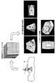
また、画像生成部14は、生成したボリュームデータをモニタ2にて表示するための各種画像を生成することができる。具体的には、画像生成部14は、ボリュームデータからMPR画像やレンダリング画像を生成することができる。図2は、第1の実施形態に係る画像生成部の概要を説明するための図である。  In addition, theimage generation unit 14 can generate various images for displaying the generated volume data on themonitor 2. Specifically, theimage generation unit 14 can generate an MPR image and a rendering image from the volume data. FIG. 2 is a diagram for explaining the outline of the image generation unit according to the first embodiment.

すなわち、図2に示すように、超音波プローブ1により被検体Pの撮影部位に対して超音波の3次元走査が行なわれることで、送受信部11は、ボリュームデータを生成する。そして、画像生成部14は、ボリュームデータをモニタ2に表示するための画像として、例えば、操作者からの指示により、図2に示すように、直交3断面におけるMPR画像や、超音波プローブ1の被検体Pに対する接触面を視点とした場合のレンダリング画像や、任意の場所を視点とした場合のレンダリング画像を生成する。なお、本実施形態に係る画像生成部14は、自装置以外で生成されたボリュームデータについても、MPR画像及びレンダリング画像の生成処理を行なうことができる。  That is, as shown in FIG. 2, theultrasound probe 1 performs a three-dimensional ultrasound scan on the imaging region of the subject P, so that the transmission / reception unit 11 generates volume data. Then, theimage generation unit 14 displays, as an image for displaying volume data on themonitor 2, for example, according to an instruction from the operator, as shown in FIG. A rendering image when the contact surface with respect to the subject P is a viewpoint or a rendering image when an arbitrary place is a viewpoint is generated. Note that theimage generation unit 14 according to the present embodiment can perform MPR image and rendering image generation processing for volume data generated by devices other than its own device.

また、画像生成部14は、ボリュームデータに含まれる管腔を描出したカーブドMPR画像などを生成する。画像生成部14によるカーブドMPR画像の生成処理については、後に詳述する。  In addition, theimage generation unit 14 generates a curved MPR image or the like depicting the lumen included in the volume data. The curved MPR image generation process by theimage generation unit 14 will be described in detail later.

なお、画像生成部14は、超音波画像に、種々のパラメータの文字情報、目盛り、ボディーマークなどを合成した合成画像を生成することもできる。  Theimage generation unit 14 can also generate a composite image in which character information, scales, body marks, and the like of various parameters are combined with the ultrasonic image.

図1に戻って、画像メモリ15は、画像生成部14が生成した超音波画像を記憶するメモリである。また、画像メモリ15は、Bモード処理部12やドプラ処理部13が生成したデータを記憶することも可能である。  Returning to FIG. 1, theimage memory 15 is a memory for storing the ultrasonic image generated by theimage generation unit 14. Theimage memory 15 can also store data generated by the B-mode processing unit 12 and theDoppler processing unit 13.

内部記憶部16は、超音波送受信、画像処理及び表示処理を行なうための制御プログラムや、診断情報(例えば、患者ID、医師の所見など)や、診断プロトコルや各種ボディーマークなどの各種データを記憶する。また、内部記憶部16は、必要に応じて、画像メモリ15が記憶する画像の保管などにも使用される。  Theinternal storage unit 16 stores a control program for performing ultrasonic transmission / reception, image processing and display processing, diagnostic information (for example, patient ID, doctor's findings, etc.), various data such as a diagnostic protocol and various body marks. To do. Theinternal storage unit 16 is also used for storing images stored in theimage memory 15 as necessary.

さらに、内部記憶部16は、外部装置4から転送された各種医用画像の保管にも使用される。具体的には、内部記憶部16は、外部装置4から転送されたボリュームデータを記憶する。例えば、内部記憶部16は、3次元のX線CT画像(以下、X線CTボリュームデータと記載する)や、3次元のMRI画像(以下、MRIボリュームデータと記載する)、他の超音波診断装置にて生成されたボリュームデータを記憶する。また、内部記憶部16が記憶するデータは、後述するインターフェース部18を経由して、外部の周辺装置(外部装置4)へ転送することができる。  Further, theinternal storage unit 16 is also used for storing various medical images transferred from the external device 4. Specifically, theinternal storage unit 16 stores volume data transferred from the external device 4. For example, theinternal storage unit 16 stores a three-dimensional X-ray CT image (hereinafter referred to as X-ray CT volume data), a three-dimensional MRI image (hereinafter referred to as MRI volume data), and other ultrasonic diagnosis. The volume data generated by the device is stored. The data stored in theinternal storage unit 16 can be transferred to an external peripheral device (external device 4) via theinterface unit 18 described later.

なお、本実施形態は、操作者が所望する画像データ(ボリュームデータ)がフレキシブルディスク(FD)、CD−ROM、MO、DVDなどの記憶媒体を介して、内部記憶部16に格納される場合であっても適用可能である。また、本実施形態は、操作者が所望する画像データ(ボリュームデータ)を記憶する記憶装置が、内部記憶部16以外に設置される場合であっても適用可能である。  In the present embodiment, image data (volume data) desired by the operator is stored in theinternal storage unit 16 via a storage medium such as a flexible disk (FD), CD-ROM, MO, or DVD. Even if it exists, it is applicable. Further, the present embodiment is applicable even when a storage device that stores image data (volume data) desired by the operator is installed other than theinternal storage unit 16.

制御部17は、情報処理装置(計算機)としての機能を実現する制御プロセッサ(CPU:Central Processing Unit)であり、超音波診断装置の処理全体を制御する。具体的には、制御部17は、入力装置3を介して操作者から入力された各種設定要求や、内部記憶部16から読込んだ各種制御プログラム及び各種データに基づき、送受信部11、Bモード処理部12、ドプラ処理部13及び画像生成部14の処理を制御する。また、制御部17は、画像メモリ15が記憶する超音波画像や、内部記憶部16が記憶する各種画像、又は、画像生成部14による処理を行なうためのGUI、画像生成部14の処理結果などをモニタ2にて表示するように制御する。また、制御部17は、操作者から入力装置3を介して受け付けたボリュームデータが外部装置4からネットワーク200及びインターフェース部18を介して内部記憶部16に転送されるように、制御する。  Thecontrol unit 17 is a control processor (CPU: Central Processing Unit) that realizes a function as an information processing apparatus (computer), and controls the entire processing of the ultrasonic diagnostic apparatus. Specifically, thecontrol unit 17 is based on various setting requests input from the operator via theinput device 3 and various control programs and various data read from theinternal storage unit 16. The processing of theprocessing unit 12, theDoppler processing unit 13, and theimage generation unit 14 is controlled. Thecontrol unit 17 also includes an ultrasonic image stored in theimage memory 15, various images stored in theinternal storage unit 16, a GUI for performing processing by theimage generation unit 14, a processing result of theimage generation unit 14, and the like. Is displayed on themonitor 2. Further, thecontrol unit 17 performs control so that volume data received from the operator via theinput device 3 is transferred from the external device 4 to theinternal storage unit 16 via thenetwork 200 and theinterface unit 18.

インターフェース部18は、入力装置3、ネットワーク200及び外部装置4に対するインターフェースである。入力装置3が受け付けた操作者からの各種設定情報及び各種指示は、インターフェース部18により、制御部17に転送される。また、入力装置3が操作者から受け付けた画像データの転送要求は、インターフェース部18により、ネットワーク200を介して外部装置4に通知される。また、外部装置4が転送した画像データは、インターフェース部18により、内部記憶部16に格納される。  Theinterface unit 18 is an interface for theinput device 3, thenetwork 200, and the external device 4. Various setting information and various instructions from the operator received by theinput device 3 are transferred to thecontrol unit 17 by theinterface unit 18. Also, the transfer request of the image data received from the operator by theinput device 3 is notified to the external device 4 via thenetwork 200 by theinterface unit 18. The image data transferred by the external device 4 is stored in theinternal storage unit 16 by theinterface unit 18.

以上、第1の実施形態に係る超音波診断装置の全体構成について説明した。かかる構成のもと、第1の実施形態に係る超音波診断装置は、以下、詳細に説明する画像生成部14の処理により、管腔内を簡便に観察することができるように構成されている。  The overall configuration of the ultrasonic diagnostic apparatus according to the first embodiment has been described above. Based on this configuration, the ultrasonic diagnostic apparatus according to the first embodiment is configured so that the inside of the lumen can be easily observed by the processing of theimage generation unit 14 described in detail below. .

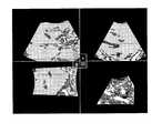
ここで、まず、従来技術において、管腔内を簡便に観察することが困難となる場合について説明する。図3は、従来技術における課題を説明するための図である。図3においては、モニタ2にて、管腔が描出された直交3断面のMPR画像と、輝度値を白黒反転させるcavityモードで表示させた指定方向からのレンダリング画像とを表示させた状態を示す。ここで、図3においては、左側の上下及び右側の上の画像が直交3断面のMPR画像を示し、右下の画像がcavityモードでのレンダリング画像を示す。  Here, first, a case where it is difficult to simply observe the inside of the lumen in the conventional technique will be described. FIG. 3 is a diagram for explaining a problem in the prior art. FIG. 3 shows a state in which themonitor 2 displays an MPR image of three orthogonal cross-sections in which a lumen is depicted and a rendering image from a designated direction displayed in a cavity mode in which the luminance value is reversed in black and white. . Here, in FIG. 3, the upper left and upper and right upper images show MPR images having three orthogonal cross sections, and the lower right image shows a rendered image in the cavity mode.

例えば、観察者は、図3に示す直交3断面のMPR画像をトラックボールによりスライス断面を並進させたり、回転させたりしながら、管腔内の性状などを観察する。この方法においては、例えば、腹部臓器のように管腔が分岐して3次元に複雑に走行する場合に、管腔をトレースすることが容易ではない。また、cavityモードでのレンダリング画像においては、管腔の形状については把握することができるが、管腔内の病変部位について、壁や壁の内側の観察が困難である。  For example, the observer observes the properties in the lumen while translating or rotating the slice cross section of the MPR image of the three orthogonal cross sections shown in FIG. 3 with a trackball. In this method, for example, when a lumen branches and travels in a three-dimensional manner like an abdominal organ, it is not easy to trace the lumen. In addition, in the rendering image in the cavity mode, the shape of the lumen can be grasped, but it is difficult to observe the wall and the inside of the wall of the lesion site in the lumen.

例えば、管腔より発生して、壁内に浸潤する胆管癌や乳癌などの病変部位は、管腔形状や内腔面のみならず、壁内部の性状の観察が重要であるが、上述した従来技術では、管腔内の観察が容易ではなく、管腔内を簡便に観察することが困難である。  For example, for lesions such as bile duct cancer and breast cancer that originate from the lumen and infiltrate into the wall, it is important to observe not only the shape of the lumen and the surface of the lumen, but also the properties inside the wall. In the technique, observation inside the lumen is not easy, and it is difficult to simply observe inside the lumen.

そこで、本実施形態では、以下に詳細に記載する画像生成部14の処理により、管腔のカーブドMPRを生成して、観察者に対して表示することにより、管腔内を簡便に観察することを可能にする。  Therefore, in the present embodiment, the inside of the lumen can be easily observed by generating a curved MPR of the lumen and displaying it to the observer by the processing of theimage generation unit 14 described in detail below. Enable.

図4は、第1の実施形態に係る画像生成部14の構成の一例を示す図である。図4に示すように、画像生成部14は、トレースライン(trace line)設定部141と、カーブド(curved)MPR画像生成部142と、仮想内視鏡画像生成部143とを有する。  FIG. 4 is a diagram illustrating an example of the configuration of theimage generation unit 14 according to the first embodiment. As illustrated in FIG. 4, theimage generation unit 14 includes a traceline setting unit 141, a curved MPRimage generation unit 142, and a virtual endoscopeimage generation unit 143.

トレースライン設定部141は、超音波プローブ1から送信される送信信号を被検体に3次元的に走査することで収集された3次元画像データに含まれる管腔に芯線を設定する。具体的には、トレースライン設定部141は、画像メモリ15或いは内部記憶部16によって記憶されたボリュームデータを読み出し、ボリュームデータに含まれる管腔を抽出し、抽出した管腔に芯線(以下、トレースラインと記す)を設定する。図5は、第1の実施形態に係るトレースライン設定部141による処理の一例を説明するための図である。  The traceline setting unit 141 sets a core line in a lumen included in three-dimensional image data collected by three-dimensionally scanning a subject with a transmission signal transmitted from theultrasonic probe 1. Specifically, the traceline setting unit 141 reads the volume data stored in theimage memory 15 or theinternal storage unit 16, extracts a lumen included in the volume data, and extracts a core line (hereinafter referred to as a trace) to the extracted lumen. Set as line). FIG. 5 is a diagram for explaining an example of processing by the traceline setting unit 141 according to the first embodiment.

ここで、まず、トレースライン設定部141の処理を行なうために、観察者は、入力装置3を介して、処理対象となるボリュームデータを指定し、更に、直交3断面(A面、B面、C面)のMPR画像の表示要求を行なう。表示要求を入力装置3から通知された制御部17は、画像生成部14に対して、操作者が指定したボリュームデータから直交3断面のMPR画像を生成するように制御する。そして、モニタ2は、制御部17の制御により、画像生成部14が生成した直交3断面のMPR画像を表示する。  Here, first, in order to perform the processing of the traceline setting unit 141, the observer designates volume data to be processed via theinput device 3, and further, three orthogonal cross sections (A surface, B surface, A request to display the MPR image of (C-plane) is made. Thecontrol unit 17 notified of the display request from theinput device 3 controls theimage generation unit 14 to generate an MPR image having three orthogonal cross sections from the volume data designated by the operator. Themonitor 2 displays the MPR image of the three orthogonal cross sections generated by theimage generation unit 14 under the control of thecontrol unit 17.

観察者は、モニタ2に表示されたMPR画像に描出された管腔に、トレースライン設定部141がトレースラインを設定するための始点を入力装置3が有する描画機能を用いて設定する。制御部17は、入力装置3が受け付けた始点のボリュームデータにおける位置情報を取得し、取得した始点の位置情報をトレースライン設定部141に通知する。  The observer sets a starting point for the traceline setting unit 141 to set the trace line in the lumen drawn in the MPR image displayed on themonitor 2 by using the drawing function of theinput device 3. Thecontrol unit 17 acquires position information in the volume data of the start point received by theinput device 3, and notifies the traceline setting unit 141 of the acquired position information of the start point.

トレースライン設定部141は、始点におけるボリュームデータの輝度を取得し、取得した輝度に対して所定の閾値の範囲内となる輝度を有するボクセル(voxel)を順次特定する。これにより、トレースライン設定部141は、例えば、図5に示すように、ボリュームデータD1に含まれる管腔領域300を抽出する。すなわち、トレースライン設定部141は、モルフォロジー演算(Dilation, Erosion, Opening, Closing)を行なうことで、管腔領域を抽出する。そして、トレースライン設定部141は、図5に示すように、管腔領域300にトレースライン301を設定する。例えば、トレースライン設定部141は、管腔領域300を細線化処理することでトレースライン301を設定する。換言すると、トレースライン設定部141は、トレースライン301のボリュームデータにおける位置情報を、管腔領域300のトレースライン情報として設定する。  The traceline setting unit 141 acquires the luminance of the volume data at the start point, and sequentially specifies voxels having luminance that falls within a predetermined threshold range with respect to the acquired luminance. Thereby, the traceline setting unit 141 extracts thelumen region 300 included in the volume data D1, for example, as shown in FIG. That is, the traceline setting unit 141 extracts a luminal region by performing a morphological operation (Dilation, Erosion, Opening, Closing). Then, the traceline setting unit 141 sets thetrace line 301 in thelumen region 300 as shown in FIG. For example, the traceline setting unit 141 sets thetrace line 301 by thinning thelumen region 300. In other words, the traceline setting unit 141 sets the position information in the volume data of thetrace line 301 as the trace line information of thelumen region 300.

なお、トレースライン設定部141は、管腔領域が分岐している場合、予め設定された選択条件に基づいて、トレースラインの設定方向を選択することができる。例えば、分岐する管腔領域において、分岐点を操作者が設定したとする。かかる場合には、トレースライン設定部141は、2方向に分岐する管腔領域を抽出する。そして、トレースライン設定部141は、トレースラインとして、分岐点で2つに別れる2本のトレースラインを設定することができる。  Note that when the lumen region is branched, the traceline setting unit 141 can select the setting direction of the trace line based on a preset selection condition. For example, assume that the operator sets a branch point in a branching lumen region. In such a case, the traceline setting unit 141 extracts a lumen region that branches in two directions. Then, the traceline setting unit 141 can set two trace lines that are divided into two at the branch point as the trace lines.

ここで、選択条件として、「トレースラインの設定方向:長さ優先」が設定されている場合には、トレースライン設定部141は、2本のトレースラインの長さを比較して、より長いトレースラインを設定できる方向のトレースラインを設定する。或いは、選択条件として、「トレースラインの設定方向:管腔の太さ優先」が設定されている場合には、トレースライン設定部141は、2方向に分岐する2つの管腔のうち、管腔の太い方向のトレースラインを設定する。  Here, when “setting direction of trace line: length priority” is set as the selection condition, the traceline setting unit 141 compares the lengths of the two trace lines to obtain a longer trace. Set the trace line in the direction that can set the line. Alternatively, when “trace line setting direction: lumen thickness priority” is set as the selection condition, the traceline setting unit 141 selects a lumen from two lumens that branch in two directions. Set the trace line in the thick direction.

なお、上述したトレースライン設定部141の処理は、操作者により手動で実行される場合であっても良い。また、本実施形態は、管腔領域が分岐している場合に、操作者がトレースラインの設定方向を指定する場合であっても良い。例えば、観察者は、モニタ2にて表示させた分岐点付近の断面画像上で、所望する方向にカーソルを移動させることでトレースラインの設定方向を指定する。  Note that the processing of the traceline setting unit 141 described above may be executed manually by an operator. Moreover, this embodiment may be a case where the operator designates the setting direction of the trace line when the lumen region is branched. For example, the observer designates the setting direction of the trace line by moving the cursor in a desired direction on the cross-sectional image near the branch point displayed on themonitor 2.

図4に戻って、カーブドMPR画像生成部142は、トレースライン設定部141によって設定されたトレースラインを含む断面の2次元画像を、3次元画像データから当該芯線に沿って生成する。具体的には、カーブドMPR画像生成部142は、トレースライン設定部141によって設定されたトレースラインの位置情報に基づいて、ボリュームデータにおけるトレースラインを含む任意のスライス断面のMPR画像を生成する。例えば、カーブドMPR画像生成部142は、トレースラインにおける任意の始点から終点までを含む断面の2次元画像を、ボリュームデータから生成する。  Returning to FIG. 4, the curved MPRimage generation unit 142 generates a two-dimensional image of the cross section including the trace line set by the traceline setting unit 141 along the core line from the three-dimensional image data. Specifically, the curved MPRimage generation unit 142 generates an MPR image of an arbitrary slice cross section including the trace line in the volume data based on the trace line position information set by the traceline setting unit 141. For example, the curved MPRimage generation unit 142 generates a two-dimensional image of a cross section including any start point to end point in the trace line from the volume data.

図6は、第1の実施形態に係るカーブドMPR画像生成部142による第1の処理を説明するための図である。図6においては、図5に示すトレースライン設定部141によるトレースラインの設定処理の後の処理について示す。例えば、カーブドMPR画像生成部142は、図6に示すように、トレースライン301上のa−b間のラインでスライスした断面のMPR画像を生成する。そして、カーブドMPR画像生成部142は、トレースライン301に沿って徐々に移動しながら、トレースライン301上の任意の区間のラインごとにスライスしたMPR画像を複数生成する。すなわち、管腔画像生成部142は、管腔領域300の全域に渡って、管腔の略中心位置を通過する断面を含むMPR画像を生成する。ここで、任意の区間としては、例えば、トレースライン301がほぼ直線となっている区間などである。  FIG. 6 is a diagram for explaining the first processing by the curved MPRimage generation unit 142 according to the first embodiment. FIG. 6 shows processing after the trace line setting processing by the traceline setting unit 141 shown in FIG. For example, the curved MPRimage generation unit 142 generates an MPR image of a cross section sliced by a line between a and b on thetrace line 301 as shown in FIG. Then, the curved MPRimage generation unit 142 generates a plurality of MPR images sliced for each line in an arbitrary section on thetrace line 301 while gradually moving along thetrace line 301. That is, the lumenimage generation unit 142 generates an MPR image including a cross section that passes through the approximate center position of the lumen over theentire lumen region 300. Here, the arbitrary section is, for example, a section in which thetrace line 301 is substantially a straight line.

そして、カーブドMPR画像生成部142は、生成した複数のMPR画像それぞれから管腔を含む任意の領域を抽出し、抽出した任意の領域それぞれをトレースラインに沿って合成したカーブドMPR画像を生成する。具体的には、カーブドMPR画像生成部142は、複数のMPR画像それぞれから管腔の略中心位置を通過する断面領域を抽出し、抽出した断面領域をトレースラインの位置情報に基づいて合成したカーブドMPR画像を生成する。  Then, the curved MPRimage generation unit 142 extracts an arbitrary region including a lumen from each of the generated plurality of MPR images, and generates a curved MPR image obtained by combining the extracted arbitrary regions along the trace line. Specifically, the curved MPRimage generation unit 142 extracts a cross-sectional area that passes through the approximate center position of the lumen from each of the plurality of MPR images, and combines the extracted cross-sectional area based on the position information of the trace line. An MPR image is generated.

図7は、第1の実施形態に係るカーブドMPR画像生成部142による第2の処理を説明するための図である。図7においては、図6に示すMPR画像の生成処理の後の処理について示す。例えば、カーブドMPR画像生成部142は、図7に示すように、生成した複数のMPR画像から矢印302で示す幅の断面領域をそれぞれ抽出する。なお、矢印302で示す幅は、観察者によって任意に設定することができる。例えば、矢印302で示す幅は、MPR画像を生成する際に用いた任意の区間、或いは、観察者が所望する任意の長さに設定される。  FIG. 7 is a diagram for explaining the second processing by the curved MPRimage generation unit 142 according to the first embodiment. FIG. 7 shows a process after the MPR image generation process shown in FIG. For example, as shown in FIG. 7, the curved MPRimage generation unit 142 extracts cross-sectional areas each having a width indicated by anarrow 302 from a plurality of generated MPR images. Note that the width indicated by thearrow 302 can be arbitrarily set by the observer. For example, the width indicated by thearrow 302 is set to an arbitrary section used when generating the MPR image or an arbitrary length desired by the observer.

そして、カーブドMPR画像生成部142は、図7に示すように、複数の管腔画像からそれぞれ抽出した断面領域をトレースラインの位置情報に基づいて合成したカーブドMPR画像を生成する。すなわち、カーブドMPR画像生成部142は、図7に示すように、管腔領域の全域の断面が描出されたカーブドMPR画像を生成する。そして、カーブドMPR画像生成部142は、生成したカーブドMPR画像を画像メモリ15に格納する。  Then, as shown in FIG. 7, the curved MPRimage generation unit 142 generates a curved MPR image obtained by synthesizing the cross-sectional areas respectively extracted from the plurality of lumen images based on the position information of the trace line. That is, as shown in FIG. 7, the curved MPRimage generation unit 142 generates a curved MPR image in which a cross section of the entire lumen region is depicted. Then, the curved MPRimage generation unit 142 stores the generated curved MPR image in theimage memory 15.

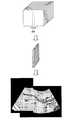
図4に戻って、仮想内視鏡画像生成部143は、トレースライン設定部141によって設定されたトレースラインに沿って、任意の視点及び視線方向からの仮想内視鏡画像を生成する。具体的には、仮想内視鏡画像生成部143は、トレースラインの軌道に沿って、任意の方向に、一定の距離間隔及び一定の時間間隔で視点を移動させ、各視線方向から管腔内を投影した仮想内視鏡画像を、ボリュームデータを用いて生成する。図8Aは、第1の実施形態に係る仮想内視鏡画像生成部143による処理の一例を説明するための図である。  Returning to FIG. 4, the virtual endoscopicimage generation unit 143 generates a virtual endoscopic image from an arbitrary viewpoint and line-of-sight direction along the trace line set by the traceline setting unit 141. Specifically, the virtual endoscopicimage generation unit 143 moves the viewpoint in a certain distance interval and a certain time interval along the trace line trajectory, and from each gaze direction to the lumen Is generated using volume data. FIG. 8A is a diagram for describing an example of processing by the virtual endoscopeimage generation unit 143 according to the first embodiment.

ここで、まず、仮想内視鏡画像生成部143が処理を行うために、観察者によって視点及び視線方向が設定される。例えば、図8Aの上側の図の矢印303に示すように、モニタ2にて表示されたMPR画像に描出された管腔に、観察者によって視点及び視線方向が設定される。仮想内視鏡画像生成部143は、図8Aの下側の図に示すように、トレースライン301上の視点304から視線方向305に、管腔内を投影した仮想内視鏡画像を生成する。このとき、仮想内視鏡画像生成部143は、図8Aの下側の図に示すように、視線方向305を中心とする視野角であるFOV(Field Of View)角にて定まる近平面306及び遠平面307の範囲に向けて視点304から放射状に透視投影する。そして、仮想内視鏡画像生成部143は、一定の距離間隔及び一定の時間間隔で視点を移動させながら、各視線方向から管腔内を投影した仮想内視鏡画像をそれぞれ生成し、生成した仮想内視鏡画像を画像メモリ15に格納する。  Here, first, the viewpoint and the line-of-sight direction are set by the observer in order for the virtual endoscopeimage generation unit 143 to perform processing. For example, as indicated by anarrow 303 in the upper diagram of FIG. 8A, the viewpoint and the line-of-sight direction are set by the observer in the lumen depicted in the MPR image displayed on themonitor 2. The virtual endoscopeimage generation unit 143 generates a virtual endoscope image in which the inside of the lumen is projected from theviewpoint 304 on thetrace line 301 in the line-of-sight direction 305, as shown in the lower diagram of FIG. 8A. At this time, as shown in the lower diagram of FIG. 8A, the virtual endoscopicimage generation unit 143 has anear plane 306 determined by a FOV (Field Of View) angle that is a viewing angle centered on the line-of-sight direction 305, and A perspective projection is performed radially from theviewpoint 304 toward the range of thefar plane 307. Then, the virtual endoscopicimage generation unit 143 generates and generates virtual endoscopic images in which the inside of the lumen is projected from each line-of-sight direction while moving the viewpoint at constant distance intervals and constant time intervals. The virtual endoscopic image is stored in theimage memory 15.

図8Bは、第1の実施形態に係る仮想内視鏡画像生成部143によって生成された仮想内視鏡画像の従来の表示例を示す図である。図8Bにおいては、仮想内視鏡画像を右下に示し、左側の上下及び右上に、視点位置における直交3断面のMPR画像を示す。また、図8Bにおいては、制御部17が、画像メモリ15から仮想内視鏡画像を読み出し、読み出した仮想内視鏡画像をモニタ2にて表示させた状態を示す。  FIG. 8B is a diagram illustrating a conventional display example of the virtual endoscopic image generated by the virtual endoscopicimage generating unit 143 according to the first embodiment. In FIG. 8B, the virtual endoscopic image is shown in the lower right, and the MPR images of three orthogonal cross sections at the viewpoint position are shown in the upper left and lower and upper right. 8B shows a state in which thecontrol unit 17 reads the virtual endoscopic image from theimage memory 15 and displays the read virtual endoscopic image on themonitor 2. FIG.

例えば、図8Bに示すように、制御部17は、仮想内視鏡画像生成部143によって生成された各視線方向から管腔内を投影した仮想内視鏡画像と、当該仮想内視鏡画像が生成された視点位置における直交3断面のMPR画像をモニタ2に表示させる。ここで、制御部17は、仮想内視鏡生成部143が仮想内視鏡画像を生成する際に視点を移動した時間間隔で仮想内視鏡画像を更新することで、管腔内を視線方向に移動しながら観察できる動画像(フライスルー画像:flythrough画像)を表示させることが可能である。なお、フライスルー画像が表示される場合には、視点の移動に伴って、直交3断面のMPR画像も更新される。  For example, as illustrated in FIG. 8B, thecontrol unit 17 includes a virtual endoscopic image obtained by projecting the inside of the lumen from each line-of-sight direction generated by the virtual endoscopicimage generation unit 143, and the virtual endoscopic image. The MPR image of the three orthogonal cross sections at the generated viewpoint position is displayed on themonitor 2. Here, thecontrol unit 17 updates the virtual endoscopic image at a time interval when the viewpoint is moved when the virtualendoscope generating unit 143 generates the virtual endoscopic image, so that the gaze direction in the lumen It is possible to display a moving image that can be observed while moving to (flythrough image). When a fly-through image is displayed, the MPR image having three orthogonal cross sections is also updated as the viewpoint moves.

本実施形態に係る超音波診断装置100は、上述したカーブドMPR画像と、フライスルー画像とをモニタに並列表示することで、管腔内の性状をより把握しやすくすることができる。具体的には、制御部17は、仮想内視鏡画像生成部143によって生成された仮想内視鏡画像をモニタ2にて表示させる場合に、カーブドMPR画像生成部142によって生成されたカーブドMPR画像上に、当該仮想内視鏡画像の視点及び視線方向の情報を連動して表示させる。  The ultrasonicdiagnostic apparatus 100 according to the present embodiment can more easily grasp the properties in the lumen by displaying the curved MPR image and the fly-through image described above in parallel on the monitor. Specifically, thecontrol unit 17 displays the curved MPR image generated by the curved MPRimage generation unit 142 when displaying the virtual endoscopic image generated by the virtual endoscopicimage generation unit 143 on themonitor 2. On the top, information on the viewpoint and line-of-sight direction of the virtual endoscopic image is displayed in conjunction with each other.

図9Aは、第1の実施形態に係る制御部17によるカーブドMPR画像の第1の表示例を示す図である。例えば、制御部17は、図9Aに示すように、管腔のフライスルー画像と、当該管腔を直線308(鉛直面)でスライスした場合のカーブドMPR画像と、現時点の視点におけるMPR画像とを、モニタ2にて並列表示させる。ここで、制御部17は、図9Aの矢印310及び311に示すように、フライスルー画像の視点及び視線方向をカーブドMPR画像及びMPR画像それぞれに表示させる。そして、制御部17は、フライスルー画像における視点の移動に伴って、カーブドMPR画像及びMPR画像上の矢印310及び311を移動させる。すなわち、制御部17は、フライスルー画像と、カーブドMPR画像と、MPR画像との対応関係を明瞭にすることで、観察者は3種の画像の比較を容易に行なうことができ、管腔内の性状をより把握しやすくすることが可能である。  FIG. 9A is a diagram illustrating a first display example of the curved MPR image by thecontrol unit 17 according to the first embodiment. For example, as shown in FIG. 9A, thecontrol unit 17 generates a lumen fly-through image, a curved MPR image obtained by slicing the lumen along a straight line 308 (vertical plane), and an MPR image at the current viewpoint. , And display them in parallel on themonitor 2. Here, as shown byarrows 310 and 311 in FIG. 9A, thecontrol unit 17 displays the viewpoint and line-of-sight direction of the fly-through image on the curved MPR image and the MPR image, respectively. Then, thecontrol unit 17 moves the curved MPR image and thearrows 310 and 311 on the MPR image with the movement of the viewpoint in the fly-through image. That is, thecontrol unit 17 clarifies the correspondence between the fly-through image, the curved MPR image, and the MPR image, so that the observer can easily compare the three types of images. It is possible to make it easier to grasp the properties of

また、第1の実施形態に係る超音波診断装置100は、管腔を任意の断面でスライスしたカーブドMPR画像を生成して表示することができる。図9Bは、第1の実施形態に係る制御部17によるカーブドMPR画像の第2の表示例を示す図である。例えば、制御部17は、図9Bに示すように、管腔を直線312(水平面)でスライスした場合のカーブドMPR画像を表示することも可能である。すなわち、第1の実施形態に係る超音波診断装置100においては、カーブドMPR画像生成部142に生成させるMPR画像のスライス断面を変化させることで、カーブドMPR画像の断面を種々設定することが可能である。  Further, the ultrasonicdiagnostic apparatus 100 according to the first embodiment can generate and display a curved MPR image obtained by slicing a lumen with an arbitrary cross section. FIG. 9B is a diagram illustrating a second display example of the curved MPR image by thecontrol unit 17 according to the first embodiment. For example, as shown in FIG. 9B, thecontrol unit 17 can also display a curved MPR image when the lumen is sliced along a straight line 312 (horizontal plane). That is, in the ultrasonicdiagnostic apparatus 100 according to the first embodiment, various sections of the curved MPR image can be set by changing the slice section of the MPR image generated by the curved MPRimage generation unit 142. is there.

また、第1の実施形態に係る超音波診断装置100は、カーブドMPR画像上で管腔長及び内腔の直径などを計測するための計測機能を備えることも可能である。例えば、超音波診断装置100は、観察者が入力装置3を介してモニタ2に描出されたカーブドMPR画像上の任意の範囲を指定した際に、当該任意の範囲に対して種々の計測を行うことが可能な計測機能を備えることが可能である。  The ultrasonicdiagnostic apparatus 100 according to the first embodiment can also include a measurement function for measuring a lumen length, a lumen diameter, and the like on a curved MPR image. For example, when the observer designates an arbitrary range on the curved MPR image drawn on themonitor 2 via theinput device 3, the ultrasonicdiagnostic apparatus 100 performs various measurements on the arbitrary range. It is possible to provide a measurement function that can be used.

なお、上述した実施形態では、カーブドMPR画像と仮想内視鏡画像とを並列表示する場合について説明したが、実施形態は、これに限定されるものではなく、例えば、カーブドMPR画像のみをモニタ2にて表示させる場合であってもよい。  In the above-described embodiment, the case where the curved MPR image and the virtual endoscopic image are displayed in parallel has been described. However, the embodiment is not limited to this, and for example, only the curved MPR image is monitored 2. It may be a case where it is displayed with.

次に、図10を用いて、第1の実施形態に係る超音波診断装置100の処理について説明する。図10は、第1の実施形態に係る超音波診断装置100による処理の手順を示すフローチャートである。図10に示すように、第1の実施形態に係る超音波診断装置100においては、操作者から開始指示を受付けると(ステップS101肯定)、トレースライン設定部141は、ボリュームデータに含まれる管腔にトレースラインを設定する(ステップS102)。なお、開始指示としては、例えば、トレースラインの始点が設定された場合などが挙げられる。  Next, processing of the ultrasonicdiagnostic apparatus 100 according to the first embodiment will be described with reference to FIG. FIG. 10 is a flowchart illustrating a processing procedure performed by the ultrasonicdiagnostic apparatus 100 according to the first embodiment. As shown in FIG. 10, in the ultrasonicdiagnostic apparatus 100 according to the first embodiment, when receiving a start instruction from the operator (Yes in step S101), the traceline setting unit 141 displays the lumen included in the volume data. A trace line is set in (Step S102). The start instruction includes, for example, a case where the start point of the trace line is set.

そして、カーブドMPR画像生成部142は、トレースライン設定部141によって設定されたトレースラインに沿って、カーブドMPR画像を生成する(ステップS103)。続いて、仮想内視鏡画像生成部143は、トレースライン設定部141によって設定されたトレースラインに沿って、仮想内視鏡画像を生成する(ステップS104)。  Then, the curved MPRimage generation unit 142 generates a curved MPR image along the trace line set by the trace line setting unit 141 (step S103). Subsequently, the virtual endoscopicimage generation unit 143 generates a virtual endoscopic image along the trace line set by the trace line setting unit 141 (step S104).

そして、制御部17は、カーブドMPR画像生成部142によって生成されたカーブドMPR画像と、仮想内視鏡画像生成部143によって生成された仮想内視鏡画像とを観察位置を連動させてモニタ2にて表示させ(ステップS105)、処理を終了する。  Then, thecontrol unit 17 links the curved MPR image generated by the curved MPRimage generation unit 142 and the virtual endoscopic image generated by the virtual endoscopicimage generation unit 143 to themonitor 2 in association with the observation position. Are displayed (step S105), and the process is terminated.

なお、開始指示を受付けるまで、超音波診断装置100は、待機状態である(ステップS101否定)。また、上述した手順では、カーブドMPR画像を生成した後に仮想内視鏡画像を生成する場合について説明したが、実施形態はこれに限定されるものではなく、仮想内視鏡画像を生成した後にカーブドMPR画像を生成する場合であってもよく、或いは、カーブドMPR画像の生成と仮想内視鏡画像の生成とを同時に平行して実行する場合であってもよい。  Note that the ultrasonicdiagnostic apparatus 100 is in a standby state until a start instruction is received (No in step S101). In the above-described procedure, the case where the virtual endoscope image is generated after the curved MPR image is generated has been described. However, the embodiment is not limited to this, and the curved endoscope image is generated after the virtual endoscope image is generated. An MPR image may be generated, or a curved MPR image and a virtual endoscope image may be generated in parallel at the same time.

上述したように、第1の実施形態によれば、トレースライン設定部141が、超音波プローブ1から送信される送信信号を被検体に3次元的に走査することで収集されたボリュームデータに含まれる管腔にトレースラインを設定する。そして、カーブドMPR画像生成部142が、トレースライン設定部141によって設定されたトレースラインを含む断面のカーブドMPR画像を、ボリュームデータから当該トレースラインに沿って生成する。そして、制御部17が、カーブドMPR画像生成部142によって生成されたカーブドMPR画像をモニタ2にて表示させる。従って、第1の実施形態に係る超音波診断装置100は、管腔の断面が正確に描出されたMPR画像を表示させることができ、管腔内を簡便に観察することを可能にする。  As described above, according to the first embodiment, the traceline setting unit 141 is included in the volume data collected by three-dimensionally scanning the subject with the transmission signal transmitted from theultrasound probe 1. Set a trace line in the lumen. Then, the curved MPRimage generation unit 142 generates a curved MPR image of a cross section including the trace line set by the traceline setting unit 141 from the volume data along the trace line. Then, thecontrol unit 17 causes themonitor 2 to display the curved MPR image generated by the curved MPRimage generation unit 142. Therefore, the ultrasonicdiagnostic apparatus 100 according to the first embodiment can display an MPR image in which a cross section of the lumen is accurately depicted, and allows the inside of the lumen to be easily observed.

また、第1の実施形態によれば、カーブドMPR画像生成部142は、トレースラインにおける任意の始点から終点までを含む断面のカーブドMPR画像を、ボリュームデータから生成する。従って、第1の実施形態に係る超音波診断装置100は、管腔の任意の位置の断面が描出されたMPR画像を表示させることができ、管腔内をより簡便に観察することを可能にする。  Further, according to the first embodiment, the curved MPRimage generation unit 142 generates a curved MPR image of a cross section including any start point to an end point in the trace line from the volume data. Therefore, the ultrasonicdiagnostic apparatus 100 according to the first embodiment can display an MPR image in which a cross-section at an arbitrary position of the lumen is depicted, and can more easily observe the inside of the lumen. To do.

また、第1の実施形態によれば、カーブドMPR画像生成部142は、ボリュームデータにおけるトレースラインを含む任意の断面でカーブドMPR画像を生成する。従って、第1の実施形態に係る超音波診断装置100は、管腔の任意の断面が描出されたMPR画像を表示させることができ、管腔内をさらに簡便に観察することを可能にする。  Further, according to the first embodiment, the curved MPRimage generation unit 142 generates a curved MPR image with an arbitrary cross section including a trace line in the volume data. Therefore, the ultrasonicdiagnostic apparatus 100 according to the first embodiment can display an MPR image in which an arbitrary cross section of the lumen is depicted, and allows the inside of the lumen to be more easily observed.

また、第1の実施形態によれば、仮想内視鏡生成部143が、トレースライン設定部141によって設定された管腔のトレースラインに沿って、任意の視点及び視線方向からの仮想内視鏡画像を生成する。そして、制御部17が、仮想内視鏡生成部143によって生成された仮想内視鏡画像をモニタ2にて表示させる場合に、カーブドMPR画像生成部142によって生成されたカーブドMPR画像上に、当該仮想内視鏡画像の視点及び視線方向の情報を連動して表示させる。従って、第1の実施形態に係る超音波診断装置100は、異なる種類の画像を容易に比較させることができ、管腔内をより簡便に観察することを可能にする。  Further, according to the first embodiment, the virtualendoscope generation unit 143 is configured so that the virtual endoscope from any viewpoint and line-of-sight direction along the lumen trace line set by the traceline setting unit 141. Generate an image. Then, when thecontrol unit 17 displays the virtual endoscope image generated by the virtualendoscope generation unit 143 on themonitor 2, thecontrol unit 17 performs the above operation on the curved MPR image generated by the curved MPRimage generation unit 142. Information on the viewpoint and line-of-sight direction of the virtual endoscopic image is displayed in conjunction with each other. Therefore, the ultrasonicdiagnostic apparatus 100 according to the first embodiment can easily compare different types of images, and can more easily observe the inside of the lumen.

(第2の実施形態)
上述した第1の実施形態では、1つのボリュームデータを用いてカーブドMPR画像を生成する場合について説明した。第2の実施形態では、複数のボリュームデータを合成し、合成したボリュームデータを用いてカーブドMPR画像を生成する場合について説明する。図11は、第2の実施形態に係る画像生成部14aの構成の一例を示す図である。第2の実施形態に係る画像生成部14aは、図11に示すように、第1の実施形態に係る画像生成部14と比較して、連結ボリュームデータ生成部144を有する点が異なる。以下、これを中心に説明する。
(Second Embodiment)
In the first embodiment described above, the case where a curved MPR image is generated using one volume data has been described. In the second embodiment, a case will be described in which a plurality of volume data is combined and a curved MPR image is generated using the combined volume data. FIG. 11 is a diagram illustrating an example of the configuration of theimage generation unit 14a according to the second embodiment. As shown in FIG. 11, theimage generation unit 14a according to the second embodiment is different from theimage generation unit 14 according to the first embodiment in that it includes a connected volumedata generation unit 144. Hereinafter, this will be mainly described.

連結ボリュームデータ生成部144は、被検体に対する走査位置が異なる複数の3次元画像データを、当該3次元画像データに含まれる撮像対象部位における略同一位置にて合成した合成3次元画像データを生成する。具体的には、連結ボリュームデータ生成部144は、複数のボリュームデータそれぞれについて、ボクセルごとの特徴量を抽出する。そして、連結ボリュームデータ生成部144は、複数のボリュームデータ間で、ボクセルごとの特徴量の配置が近似した領域を抽出し、抽出した領域にて複数のボリュームデータを重ね合わせた連結ボリュームデータ(3Dパノラマデータ:three dimensional panorama data)を生成する。  The connected volumedata generation unit 144 generates combined 3D image data obtained by combining a plurality of 3D image data with different scanning positions with respect to the subject at substantially the same position in the imaging target portion included in the 3D image data. . Specifically, the concatenated volumedata generation unit 144 extracts a feature amount for each voxel for each of a plurality of volume data. Then, the concatenated volumedata generation unit 144 extracts a region in which the arrangement of the feature amount for each voxel is approximated between the plurality of volume data, and concatenated volume data (3D) in which the plurality of volume data are superimposed in the extracted region. Panorama data: three dimensional panorama data) is generated.

図12は、第2の実施形態に係る連結ボリュームデータ生成部144による処理の一例を説明するための図である。例えば、連結ボリュームデータ生成部144は、ボリュームデータD1及びボリュームデータD2それぞれについて、ボクセルごとの特徴量を抽出する。一例を挙げると、連結ボリュームデータ生成部144は、ボリュームデータD1及びボリュームデータD2それぞれについてボクセルごとの輝度値を抽出する。そして、連結ボリュームデータ生成部144は、ボリュームデータD1及びボリュームデータD2それぞれについてボクセルごとの輝度値を比較し、図12に示すように、ボリュームデータD1の右側のボクセル列と、ボリュームデータD2の左側のボクセル列とを、ボクセルごとの特徴量の配置が近似した領域として抽出する。  FIG. 12 is a diagram for explaining an example of processing performed by the linked volumedata generation unit 144 according to the second embodiment. For example, the concatenated volumedata generation unit 144 extracts a feature amount for each voxel for each of the volume data D1 and the volume data D2. For example, the concatenated volumedata generation unit 144 extracts a luminance value for each voxel for each of the volume data D1 and the volume data D2. Then, the concatenated volumedata generation unit 144 compares the luminance value for each voxel for each of the volume data D1 and the volume data D2, and as shown in FIG. 12, the right voxel string of the volume data D1 and the left side of the volume data D2 Are extracted as a region in which the arrangement of feature amounts for each voxel is approximated.

そして、連結ボリュームデータ生成部144は、図12に示すように、ボリュームデータD1とボリュームデータD2とを、抽出した領域で重ね合わせた連結ボリュームデータD3を生成し、画像メモリ15に格納する。なお、図12においては、2つのボリュームデータを連結する場合について示しているが、実施形態はこれに限定されるものではなく、任意の数のボリュームデータを連結することが可能であり、例えば、3つ以上のボリュームデータを連結する場合であってもよい。  Then, the concatenated volumedata generation unit 144 generates concatenated volume data D3 obtained by superimposing the volume data D1 and the volume data D2 in the extracted area, and stores the concatenated volume data D3 in theimage memory 15, as shown in FIG. FIG. 12 shows a case where two volume data are connected, but the embodiment is not limited to this, and any number of volume data can be connected. For example, It may be a case where three or more volume data are concatenated.

トレースライン設定部141は、連結ボリュームデータ生成部144によって生成された連結ボリュームデータに含まれる管腔にトレースラインを設定する。具体的には、トレースライン設定部141は、画像メモリ15によって記憶された連結ボリュームデータから生成されたMPR画像にトレースラインの始点が設定されると、設定された始点に基づいて、連結ボリュームデータに含まれる管腔にトレースラインを設定する。  The traceline setting unit 141 sets a trace line in the lumen included in the connected volume data generated by the connected volumedata generating unit 144. Specifically, when the start point of the trace line is set in the MPR image generated from the connected volume data stored in theimage memory 15, the traceline setting unit 141 sets the connected volume data based on the set start point. Trace lines are set in the lumens included in

カーブドMPR画像生成部142は、トレースライン設定部141によって設定されたトレースラインを含む断面のカーブドMPR画像を、連結ボリュームデータから当該トレースラインに沿って生成する。図13は、第2の実施形態に係るカーブドMPR画像生成部142による処理の一例を説明するための図である。  The curved MPRimage generation unit 142 generates a curved MPR image of a cross section including the trace line set by the traceline setting unit 141 from the connected volume data along the trace line. FIG. 13 is a diagram for explaining an example of processing by the curved MPRimage generation unit 142 according to the second embodiment.

例えば、カーブドMPR画像生成部142は、図13の左上の図に示す連結ボリュームデータにトレースラインが設定されると、図13の左下の図に示すように、設定されたトレースラインに沿って、MPR画像を生成する。すなわち、第2の実施形態に係るカーブドMPR画像生成部142は、図13の右側の図に示すように、第1の実施形態と比較して、より広い領域を網羅したカーブドMPR画像を生成することとなる。  For example, when the trace line is set in the concatenated volume data shown in the upper left diagram of FIG. 13, the curved MPRimage generation unit 142 follows the set trace line as shown in the lower left diagram of FIG. 13. An MPR image is generated. That is, the curved MPRimage generation unit 142 according to the second embodiment generates a curved MPR image that covers a wider area as compared to the first embodiment, as illustrated in the right side of FIG. It will be.

次に、図14を用いて、第2の実施形態に係る超音波診断装置100の処理について説明する。図14は、第2の実施形態に係る超音波診断装置100による処理の手順を示すフローチャートである。図14に示すように、第2の実施形態に係る超音波診断装置100においては、操作者から開始指示を受付けると(ステップS201肯定)、連結ボリュームデータ生成部144は、複数のボリュームデータを連結させた連結ボリュームデータを生成する(ステップS202)。そして、トレースライン設定部141は、連結ボリュームデータに含まれる管腔にトレースラインを設定する(ステップS203)。なお、開始指示としては、例えば、操作者から連結ボリュームデータの生成コマンドを受信した場合などが挙げられる。  Next, processing of the ultrasonicdiagnostic apparatus 100 according to the second embodiment will be described with reference to FIG. FIG. 14 is a flowchart illustrating a processing procedure performed by the ultrasonicdiagnostic apparatus 100 according to the second embodiment. As illustrated in FIG. 14, in the ultrasonicdiagnostic apparatus 100 according to the second embodiment, when a start instruction is received from the operator (Yes in step S201), the connected volumedata generation unit 144 connects a plurality of volume data. Generated concatenated volume data is generated (step S202). Then, the traceline setting unit 141 sets a trace line in the lumen included in the connected volume data (step S203). The start instruction includes, for example, a case where a linked volume data generation command is received from the operator.

そして、カーブドMPR画像生成部142は、トレースライン設定部141によって設定されたトレースラインに沿って、カーブドMPR画像を生成する(ステップS204)。続いて、仮想内視鏡画像生成部143は、トレースライン設定部141によって設定されたトレースラインに沿って、仮想内視鏡画像を生成する(ステップS205)。  Then, the curved MPRimage generation unit 142 generates a curved MPR image along the trace line set by the trace line setting unit 141 (step S204). Subsequently, the virtual endoscopicimage generation unit 143 generates a virtual endoscopic image along the trace line set by the trace line setting unit 141 (step S205).

そして、制御部17は、カーブドMPR画像生成部142によって生成されたカーブドMPR画像と、仮想内視鏡画像生成部143によって生成された仮想内視鏡画像とを観察位置を連動させてモニタ2にて表示させ(ステップS206)、処理を終了する。  Then, thecontrol unit 17 links the curved MPR image generated by the curved MPRimage generation unit 142 and the virtual endoscopic image generated by the virtual endoscopicimage generation unit 143 to themonitor 2 in association with the observation position. Are displayed (step S206), and the process is terminated.

なお、開始指示を受付けるまで、超音波診断装置100は、待機状態である(ステップS201否定)。また、上述した手順では、カーブドMPR画像を生成した後に仮想内視鏡画像を生成する場合について説明したが、実施形態はこれに限定されるものではなく、仮想内視鏡画像を生成した後にカーブドMPR画像を生成する場合であってもよく、或いは、カーブドMPR画像の生成と仮想内視鏡画像の生成とを同時に平行して実行する場合であってもよい。  Note that the ultrasounddiagnostic apparatus 100 is in a standby state until a start instruction is received (No in step S201). In the above-described procedure, the case where the virtual endoscope image is generated after the curved MPR image is generated has been described. However, the embodiment is not limited to this, and the curved endoscope image is generated after the virtual endoscope image is generated. An MPR image may be generated, or a curved MPR image and a virtual endoscope image may be generated in parallel at the same time.

上述したように、第2の実施形態によれば、連結ボリュームデータ生成部144は、被検体に対する走査位置が異なる複数のボリュームデータを、当該ボリュームデータに含まれる撮像対象部位における略同一位置にて合成した連結ボリュームデータを生成する。トレースライン設定部141は、連結ボリュームデータ生成部144によって生成された連結ボリュームデータに含まれる管腔にトレースラインを設定する。そして、カーブドMPR画像生成部142は、トレースライン設定部141によって設定されたトレースラインを含む断面のMPR画像を、連結ボリュームデータから当該トレースラインに沿って生成する。従って、第2の実施形態に係る超音波診断装置100は、単一のボリュームデータ内に収まらない大きな管腔についても、カーブドMPR画像を生成することができ、種々の管腔を容易に観察することを可能にする。  As described above, according to the second embodiment, the connected volumedata generation unit 144 has a plurality of volume data with different scanning positions with respect to the subject at substantially the same position in the imaging target region included in the volume data. Generate combined volume data. The traceline setting unit 141 sets a trace line in the lumen included in the connected volume data generated by the connected volumedata generating unit 144. Then, the curved MPRimage generation unit 142 generates an MPR image of a cross section including the trace line set by the traceline setting unit 141 from the connected volume data along the trace line. Therefore, the ultrasonicdiagnostic apparatus 100 according to the second embodiment can generate a curved MPR image even for a large lumen that does not fit in a single volume data, and easily observe various lumens. Make it possible.

(第3の実施形態)
さて、これまで第1及び2の実施形態について説明したが、上述した第1及び第2の実施形態以外にも、種々の異なる形態にて実施されてよいものである。
(Third embodiment)
Although the first and second embodiments have been described so far, the present invention may be implemented in various different forms other than the first and second embodiments described above.

(1)複数の画像の並列表示
上述した第1及び第2の実施形態では、カーブドMPR画像とフライスルー画像とを並列表示する場合について説明した。しかしながら、実施形態はこれに限定されるものではなく、種々の画像を任意の組合せで並列表示させることが可能である。例えば、カーブドMPR画像と、Cavityモードによる管腔のレンダリング画像とを並列表示することが可能である。図15は、第3の実施形態に係る第1の表示例を示す図である。
(1) Parallel display of a plurality of images In the first and second embodiments described above, the case where the curved MPR image and the fly-through image are displayed in parallel has been described. However, the embodiment is not limited to this, and various images can be displayed in parallel in any combination. For example, a curved MPR image and a rendering image of a lumen in the cavity mode can be displayed in parallel. FIG. 15 is a diagram illustrating a first display example according to the third embodiment.

例えば、制御部17は、図15に示すように、管腔の鉛直面でスライスされたカーブドMPR画像(左上)と、管腔の水平面でスライスされたカーブドMPR画像(左下)と、トレースラインの始点が設定されたMPR画像(右上)と、Cavityモードによる管腔のレンダリング画像(右下)とを並列表示する。  For example, as illustrated in FIG. 15, thecontrol unit 17 performs a curved MPR image (upper left) sliced on the vertical plane of the lumen, a curved MPR image (lower left) sliced on the horizontal plane of the lumen, and a trace line. The MPR image (upper right) in which the start point is set and the rendering image (lower right) of the lumen in the cavity mode are displayed in parallel.

また、例えば、カーブドMPR画像と、Cavityモードによる管腔のレンダリング画像と、フライスルー画像とを並列表示することが可能である。図16は、第3の実施形態に係る第2の表示例を示す図である。  Further, for example, a curved MPR image, a lumen rendering image in the cavity mode, and a fly-through image can be displayed in parallel. FIG. 16 is a diagram illustrating a second display example according to the third embodiment.

例えば、制御部17は、図16に示すように、管腔の鉛直面でスライスされたカーブドMPR画像(左)と、Cavityモードによる管腔のレンダリング画像(右上)と、フライスルー画像(右下)とを並列表示する。  For example, as shown in FIG. 16, thecontrol unit 17 performs a curved MPR image (left) sliced on the vertical plane of the lumen, a rendering image (upper right) of the lumen in the cavity mode, and a fly-through image (lower right). ) Are displayed in parallel.

また、例えば、カーブドMPR画像と、フライスルー画像と、他のモダリティの医用画像とを並列表示することが可能である。図17は、第3の実施形態に係る第3の表示例を示す図である。  Further, for example, a curved MPR image, a fly-through image, and a medical image of another modality can be displayed in parallel. FIG. 17 is a diagram illustrating a third display example according to the third embodiment.

例えば、制御部17は、図17に示すように、管腔の鉛直面でスライスされたカーブドMPR画像(左)と、フライスルー画像(右下)と、X線CT画像(右上)とを並列表示する。かかる場合には、まず、制御部17は、内部記憶部16に記憶された他のモダリティの医用画像データ(ボリュームデータ)を読み出す、或いは、ネットワーク200を介して外部装置4から他の医用画像データ(ボリュームデータ)を取得するように制御する。そして、制御部17は、取得した他のモダリティのボリュームデータと、超音波診断装置100にて収集したボリュームデータとの位置合わせを実行する。例えば、制御部17は、非線形のワーピング処理や、平行移動及び回転などの線形処理を実行することで、他のモダリティのボリュームデータと、超音波診断装置100にて収集したボリュームデータとの位置合わせを実行する。  For example, as shown in FIG. 17, thecontrol unit 17 parallelizes a curved MPR image (left), a fly-through image (lower right), and an X-ray CT image (upper right) sliced on the vertical plane of the lumen. indicate. In such a case, first, thecontrol unit 17 reads medical image data (volume data) of another modality stored in theinternal storage unit 16 or other medical image data from the external device 4 via thenetwork 200. (Volume data) is acquired. Then, thecontrol unit 17 performs alignment between the acquired volume data of other modalities and the volume data collected by the ultrasonicdiagnostic apparatus 100. For example, thecontroller 17 performs non-linear warping processing and linear processing such as translation and rotation, thereby aligning the volume data of other modalities with the volume data collected by the ultrasounddiagnostic apparatus 100. Execute.

そして、制御部17は、ボリュームデータの位置合わせを実行した後に、他のモダリティのボリュームデータ及び超音波診断装置100にて収集したボリュームデータそれぞれから画像を生成する。これにより、画像間で位置の対応関係を把握することができる。すなわち、制御部17は、例えば、現時点でフライスルー画像が描出している位置が他の画像でどこに相当するのかを矢印などで表示することが可能になる。なお、図17においては、他のモダリティの医用画像としてX線CT画像が示されているが、実施形態はこれに限定されるものではなく、例えば、MR画像を用いる場合であってもよい。  Then, thecontrol unit 17 generates an image from the volume data of other modalities and the volume data collected by the ultrasonicdiagnostic apparatus 100 after performing the alignment of the volume data. Thereby, the correspondence of the position between images can be grasped. That is, for example, thecontrol unit 17 can display, using arrows or the like, where the position where the fly-through image is currently drawn corresponds to another image. In FIG. 17, an X-ray CT image is shown as a medical image of another modality, but the embodiment is not limited to this, and for example, an MR image may be used.

(2)カーブドMPR画像の生成例
上述した第1及び第2の実施形態では、3軸上を進行するトレースラインの1軸を削除した平面画像をカーブドMPR画像として生成する場合について説明した。しかしながら、実施形態はこれに限定されるものではなく、例えば、トレースラインを直線にし、それに沿ってカーブドMPR画像を生成する場合であってもよい。
(2) Generation Example of Curved MPR Image In the first and second embodiments described above, a case has been described in which a planar image from which one axis of a trace line traveling on three axes is deleted is generated as a curved MPR image. However, the embodiment is not limited to this. For example, the trace line may be a straight line and a curved MPR image may be generated along the trace line.

また、3軸上を進行するトレースラインに沿って、3次元空間に曲面で示したカーブドMPR画像を生成する場合であってもよい。図18は、第3の実施形態に係るカーブドMPR画像生成の一例を説明するための図である。例えば、カーブドMPR画像生成部142は、図18の上図に示す管腔に設定されたトレースラインに沿って、図18の下図に示すように、3次元空間に実際の管腔と同様の曲面を有したカーブドMPR画像を生成する。  Alternatively, a curved MPR image indicated by a curved surface in a three-dimensional space may be generated along a trace line that travels on three axes. FIG. 18 is a diagram for explaining an example of curved MPR image generation according to the third embodiment. For example, the curved MPRimage generation unit 142 follows the trace line set in the lumen shown in the upper diagram of FIG. 18, and a curved surface similar to the actual lumen in a three-dimensional space as shown in the lower diagram of FIG. 18. To generate a curved MPR image.

以上説明したとおり、第1の実施形態、第2の実施形態及び第3の実施形態によれば、本実施形態の超音波診断装置及び画像処理装置は、管腔内を簡便に観察することを可能にする。  As described above, according to the first embodiment, the second embodiment, and the third embodiment, the ultrasonic diagnostic apparatus and the image processing apparatus of this embodiment can easily observe the inside of a lumen. to enable.

本発明のいくつかの実施形態を説明したが、これらの実施形態は、例として提示したものであり、発明の範囲を限定することは意図していない。これら実施形態は、その他の様々な形態で実施されることが可能であり、発明の要旨を逸脱しない範囲で、種々の省略、置き換え、変更を行うことができる。これら実施形態やその変形は、発明の範囲や要旨に含まれると同様に、特許請求の範囲に記載された発明とその均等の範囲に含まれるものである。  Although several embodiments of the present invention have been described, these embodiments are presented by way of example and are not intended to limit the scope of the invention. These embodiments can be implemented in various other forms, and various omissions, replacements, and changes can be made without departing from the spirit of the invention. These embodiments and their modifications are included in the scope and gist of the invention, and are also included in the invention described in the claims and the equivalents thereof.

1 超音波プローブ
10 装置本体
14 画像生成部
17 制御部
100 超音波診断装置
141 トレースライン設定部
142 カーブドMPR画像生成部
143 仮想内視鏡画像生成部
144 連結ボリュームデータ生成部
DESCRIPTION OFSYMBOLS 1Ultrasonic probe 10 Apparatusmain body 14Image generation part 17Control part 100 Ultrasounddiagnostic apparatus 141 Traceline setting part 142 Curved MPRimage generation part 143 Virtual endoscopeimage generation part 144 Concatenated volume data generation part

Claims (10)

Translated fromJapanese
検体に対する3次元的な超音波走査により収集された3次元画像データに含まれる管腔に芯線を設定する設定手段と、
前記設定手段によって設定された芯線に沿ったカーブドMPR画像を、前記3次元画像データを用いて生成する生成手段と、
前記生成手段によって生成された前記カーブドMPR画像、および前記芯線上の視点からの仮想内視鏡画像を所定の表示部にて表示させ、前記視点の情報を前記カーブドMPR画像上に表示させる表示制御手段と、
を備えたことを特徴とする超音波診断装置。
Setting means for setting a core wire lumen included in the three-dimensional image data collectedby thethree-dimensional ultrasound scanagainst thesubject,
Generating meansfor generatinga curved MPR imagealong the coreline set by the setting meansusing the three-dimensional image data;
The curved MPR image generated by the generatingmeans, and avirtual endoscopic image from the viewpoint on the core wire is displayed at a predetermined displayunit, displayingthe information of the viewpoint Ruis displayed on the curved MPR image Control means;
An ultrasonic diagnostic apparatus comprising:
前記表示制御手段は、前記仮想内視鏡画像の視線方向の情報を前記カーブドMPR画像上に表示させることを特徴とする請求項1に記載の超音波診断装置。Wherein the display control unit, ultrasonic diagnostic apparatus according to claim 1, characterized in Rukotodisplay the line-of-sight direction information of the virtual endoscopic image on the curved MPR image. 前記生成手段は、前記芯線上の複数の視点それぞれからの仮想内視鏡画像を生成することを特徴とする請求項1又は2に記載の超音波診断装置。The ultrasonic diagnostic apparatus according to claim 1, wherein the generation unit generatesa virtual endoscopic imagefrom each of a plurality of viewpoints on the core wire . 前記設定手段は、前記3次元画像データに仮想内視鏡機能を適用し、前記仮想内視鏡画像を生成するための視点を移動させる移動線を前記芯線に設定する移動線設定手段を備えたことを特徴とする請求項1〜3のいずれか一つに記載の超音波診断装置。The setting unit includes amovement line setting unit that applies a virtual endoscope function to the three-dimensional image data and sets amovement linefor movinga viewpointfor generatingthe virtual endoscopeimage as the coreline . The ultrasonic diagnostic apparatus according to any one of claims 1 to 3. 前記移動線設定手段は、前記仮想内視鏡機能における自動の管腔追跡機能により前記視点の移動線を前記芯線に設定することを特徴とする請求項4に記載の超音波診断装置。5. The ultrasonic diagnostic apparatus according to claim 4, wherein themovement line setting means sets themovement line of the viewpoint to the coreline by an automatic lumen tracking function in the virtual endoscope function. 前記移動線設定手段は、前記仮想内視鏡機能におけるユーザインターフェースを介したユーザの操作による管腔追跡機能により前記視点の移動線を前記芯線に設定することを特徴とする請求項4に記載の超音波診断装置。Themovement line setting means sets themovement line of the viewpoint to the coreline by a lumen tracking function by a user operation via a user interface in the virtual endoscope function. Ultrasonic diagnostic equipment. 前記移動線設定手段は、前記仮想内視鏡機能により生成された前記視点の移動線を前記芯線に設定し、
前記表示制御手段は、前記仮想内視鏡画像を前記所定の表示部にて表示させる場合に、前記生成手段によって生成された前記カーブドMPR画像上に、当該仮想内視鏡画像の視点及び視線方向の情報を連動して表示させることを特徴とする請求項4〜6のいずれか一つに記載の超音波診断装置。
Themovement line setting means sets themovement line of the viewpoint generated by the virtual endoscope function to the coreline ,
Wherein the display control unit,wherein when displaying a virtual endoscopic image at the predetermined display section, onthe curved MPR image generated by the generating means, the viewpoint and line-of-sight direction of the virtual endoscopic image The ultrasonic diagnostic apparatus according to claim 4, wherein the information is displayed in conjunction with each other.
被検体に対する走査位置が異なる複数の3次元画像データを、当該3次元画像データに含まれる撮像対象部位における略同一位置にて合成した合成3次元画像データを生成する合成手段をさらに備え、
前記設定手段は、前記合成手段によって生成された合成3次元画像データに含まれる管腔に芯線を設定し、
前記生成手段は、前記設定手段によって設定された芯線に沿ったカーブドMPR画像を、前記合成3次元画像データを用いて生成することを特徴とする請求項1〜7のいずれか一つに記載の超音波診断装置。
And further comprising a combining unit that generates combined three-dimensional image data by combining a plurality of three-dimensional image data having different scanning positions with respect to the subject at substantially the same position in the imaging target portion included in the three-dimensional image data,
The setting unit sets a core wire in a lumen included in the combined three-dimensional image data generated by the combining unit;
The said production | generation means produces| generatesthe curved MPR imagealong the coreline set by the said setting meansusing the said synthetic| combination 3D image data, It is any one of Claims 1-7 characterized by the above-mentioned. Ultrasonic diagnostic equipment.
前記表示制御手段は、超音波診断装置とは異なる医用画像診断装置にて生成された医用画像を前記所定の表示部にて表示させる場合に、当該医用画像及び前記生成手段によって生成された前記カーブドMPR画像上に、前記仮想内視鏡画像の視点及び視線方向の情報を連動して表示させることを特徴とする請求項4〜7のいずれか一つに記載の超音波診断装置。The display control unit is configured to display the medical image generated by the medical image diagnostic apparatus different from the ultrasonic diagnostic apparatus on the predetermined display unit and thecurved image generated by the generation unit.The ultrasonic diagnostic apparatus according to claim 4,wherein information on a viewpoint and a line-of-sight direction of the virtual endoscopic image is displayed on anMPR image in conjunction with each other.検体に対する3次元的な超音波走査により収集された3次元画像データに含まれる管腔に芯線を設定する設定手段と、
前記設定手段によって設定された芯線に沿ったカーブドMPR画像を、前記3次元画像データを用いて生成する生成手段と、
前記生成手段によって生成された前記カーブドMPR画像、および前記芯線上の視点からの仮想内視鏡画像を所定の表示部にて表示させ、前記視点の情報を前記カーブドMPR画像上に表示させる表示制御手段と、
を備えたことを特徴とする画像処理装置。
Setting means for setting a core wire lumen included in the three-dimensional image data collectedby thethree-dimensional ultrasound scanagainst thesubject,
Generating meansfor generatinga curved MPR imagealong the coreline set by the setting meansusing the three-dimensional image data;
The curved MPR image generated by the generatingmeans, and avirtual endoscopic image from the viewpoint on the core wire is displayed at a predetermined displayunit, displayingthe information of the viewpoint Ruis displayed on the curved MPR image Control means;
An image processing apparatus comprising:
JP2011256391A2011-11-242011-11-24 Ultrasonic diagnostic apparatus and image processing apparatusActiveJP5936850B2 (en)

Priority Applications (1)

Application NumberPriority DateFiling DateTitle
JP2011256391AJP5936850B2 (en)2011-11-242011-11-24 Ultrasonic diagnostic apparatus and image processing apparatus

Applications Claiming Priority (1)

Application NumberPriority DateFiling DateTitle
JP2011256391AJP5936850B2 (en)2011-11-242011-11-24 Ultrasonic diagnostic apparatus and image processing apparatus

Publications (3)

Publication NumberPublication Date
JP2013106903A JP2013106903A (en)2013-06-06
JP2013106903A5 JP2013106903A5 (en)2015-01-08
JP5936850B2true JP5936850B2 (en)2016-06-22

Family

ID=48704299

Family Applications (1)

Application NumberTitlePriority DateFiling Date
JP2011256391AActiveJP5936850B2 (en)2011-11-242011-11-24 Ultrasonic diagnostic apparatus and image processing apparatus

Country Status (1)

CountryLink
JP (1)JP5936850B2 (en)

Families Citing this family (1)

* Cited by examiner, † Cited by third party
Publication numberPriority datePublication dateAssigneeTitle
JP6744141B2 (en)*2015-06-162020-08-19キヤノンメディカルシステムズ株式会社 Ultrasonic diagnostic device and image processing device

Family Cites Families (5)

* Cited by examiner, † Cited by third party
Publication numberPriority datePublication dateAssigneeTitle
JP4445792B2 (en)*2004-04-232010-04-07オリンパス株式会社 Insertion support system
CN101166470B (en)*2005-04-282016-04-06株式会社日立医药Image display device and method for displaying image
US20070255137A1 (en)*2006-05-012007-11-01Siemens Medical Solutions Usa, Inc.Extended volume ultrasound data display and measurement
JP5395538B2 (en)*2009-06-302014-01-22株式会社東芝 Ultrasonic diagnostic apparatus and image data display control program
JP5582787B2 (en)*2010-01-062014-09-03株式会社東芝 Medical image display device and display method

Also Published As

Publication numberPublication date
JP2013106903A (en)2013-06-06

Similar Documents

PublicationPublication DateTitle
CN101779969B (en)Ultrasound diagnosis apparatus, medical image display apparatus and medical image displaying method
JP6274421B2 (en) Ultrasonic diagnostic apparatus and control program therefor
US9173632B2 (en)Ultrasonic diagnosis system and image data display control program
US20170095226A1 (en)Ultrasonic diagnostic apparatus and medical image diagnostic apparatus
US9138202B2 (en)Ultrasonic diagnosis apparatus and medical image processing method
CN102258385B (en)Method and apparatus for imaging diagnosis
JP6125380B2 (en) Ultrasonic diagnostic apparatus, medical image processing apparatus, and image processing program
US10123780B2 (en)Medical image diagnosis apparatus, image processing apparatus, and image processing method
WO2014200099A1 (en)Ultrasonic diagnostic device
JP6071599B2 (en) Ultrasonic diagnostic apparatus, image processing apparatus, and program
JP7204424B2 (en) Medical image diagnosis device and medical image processing device
JP5689591B2 (en) Ultrasonic diagnostic apparatus and ultrasonic image processing program
KR102289393B1 (en)Imaging apparatus and controlling method thereof
JP5942217B2 (en) Ultrasonic diagnostic apparatus, ultrasonic image processing apparatus, and ultrasonic image processing program
US20120095341A1 (en)Ultrasonic image processing apparatus and ultrasonic image processing method
JP2013118998A (en)Medical image diagnosis device, ultrasound diagnostic apparatus and program
JP5981178B2 (en) Medical image diagnostic apparatus, image processing apparatus, and program
JP5936850B2 (en) Ultrasonic diagnostic apparatus and image processing apparatus
JP2013143978A (en)Ultrasonic diagnostic apparatus
JP6068017B2 (en) Ultrasonic diagnostic apparatus and image generation program
JP2012170536A (en)Ultrasonic diagnostic apparatus, image processing apparatus and image processing program
JP2012125297A (en)Ultrasonic diagnostic apparatus, image processor, and program
JP6147782B2 (en) Medical image diagnostic apparatus and medical image processing apparatus
JP2006346176A (en) Ultrasonic diagnostic apparatus and image display apparatus

Legal Events

DateCodeTitleDescription
A521Written amendment

Free format text:JAPANESE INTERMEDIATE CODE: A523

Effective date:20141117

A621Written request for application examination

Free format text:JAPANESE INTERMEDIATE CODE: A621

Effective date:20141117

A977Report on retrieval

Free format text:JAPANESE INTERMEDIATE CODE: A971007

Effective date:20150925

A131Notification of reasons for refusal

Free format text:JAPANESE INTERMEDIATE CODE: A131

Effective date:20150929

RD01Notification of change of attorney

Free format text:JAPANESE INTERMEDIATE CODE: A7421

Effective date:20151102

A521Written amendment

Free format text:JAPANESE INTERMEDIATE CODE: A523

Effective date:20151127

TRDDDecision of grant or rejection written
A01Written decision to grant a patent or to grant a registration (utility model)

Free format text:JAPANESE INTERMEDIATE CODE: A01

Effective date:20160412

A61First payment of annual fees (during grant procedure)

Free format text:JAPANESE INTERMEDIATE CODE: A61

Effective date:20160511

R150Certificate of patent or registration of utility model

Ref document number:5936850

Country of ref document:JP

Free format text:JAPANESE INTERMEDIATE CODE: R150

S111Request for change of ownership or part of ownership

Free format text:JAPANESE INTERMEDIATE CODE: R313117

R350Written notification of registration of transfer

Free format text:JAPANESE INTERMEDIATE CODE: R350

S533Written request for registration of change of name

Free format text:JAPANESE INTERMEDIATE CODE: R313533

R350Written notification of registration of transfer

Free format text:JAPANESE INTERMEDIATE CODE: R350


[8]ページ先頭

©2009-2025 Movatter.jp