JP5936379B2 - Image display device - Google Patents
Image display deviceDownload PDFInfo
- Publication number
- JP5936379B2 JP5936379B2JP2012024249AJP2012024249AJP5936379B2JP 5936379 B2JP5936379 B2JP 5936379B2JP 2012024249 AJP2012024249 AJP 2012024249AJP 2012024249 AJP2012024249 AJP 2012024249AJP 5936379 B2JP5936379 B2JP 5936379B2
- Authority
- JP
- Japan
- Prior art keywords
- image display
- eyelid
- eye
- sensor
- observer
- Prior art date
- Legal status (The legal status is an assumption and is not a legal conclusion. Google has not performed a legal analysis and makes no representation as to the accuracy of the status listed.)
- Expired - Fee Related
Links
Images


Classifications
- G—PHYSICS
- G06—COMPUTING OR CALCULATING; COUNTING
- G06F—ELECTRIC DIGITAL DATA PROCESSING
- G06F1/00—Details not covered by groups G06F3/00 - G06F13/00 and G06F21/00
- G06F1/26—Power supply means, e.g. regulation thereof
- G06F1/32—Means for saving power
- G06F1/3203—Power management, i.e. event-based initiation of a power-saving mode
- G06F1/3206—Monitoring of events, devices or parameters that trigger a change in power modality
- G06F1/3231—Monitoring the presence, absence or movement of users
- H—ELECTRICITY
- H04—ELECTRIC COMMUNICATION TECHNIQUE
- H04N—PICTORIAL COMMUNICATION, e.g. TELEVISION
- H04N5/00—Details of television systems
- H04N5/63—Generation or supply of power specially adapted for television receivers
- G—PHYSICS
- G02—OPTICS
- G02B—OPTICAL ELEMENTS, SYSTEMS OR APPARATUS
- G02B27/00—Optical systems or apparatus not provided for by any of the groups G02B1/00 - G02B26/00, G02B30/00
- G02B27/0093—Optical systems or apparatus not provided for by any of the groups G02B1/00 - G02B26/00, G02B30/00 with means for monitoring data relating to the user, e.g. head-tracking, eye-tracking
- G—PHYSICS
- G02—OPTICS
- G02B—OPTICAL ELEMENTS, SYSTEMS OR APPARATUS
- G02B27/00—Optical systems or apparatus not provided for by any of the groups G02B1/00 - G02B26/00, G02B30/00
- G02B27/01—Head-up displays
- G02B27/017—Head mounted
- G—PHYSICS
- G06—COMPUTING OR CALCULATING; COUNTING
- G06F—ELECTRIC DIGITAL DATA PROCESSING
- G06F1/00—Details not covered by groups G06F3/00 - G06F13/00 and G06F21/00
- G06F1/26—Power supply means, e.g. regulation thereof
- G06F1/32—Means for saving power
- G06F1/3203—Power management, i.e. event-based initiation of a power-saving mode
- G06F1/3234—Power saving characterised by the action undertaken
- G06F1/325—Power saving in peripheral device
- G06F1/3265—Power saving in display device
- G—PHYSICS
- G06—COMPUTING OR CALCULATING; COUNTING
- G06F—ELECTRIC DIGITAL DATA PROCESSING
- G06F3/00—Input arrangements for transferring data to be processed into a form capable of being handled by the computer; Output arrangements for transferring data from processing unit to output unit, e.g. interface arrangements
- G06F3/01—Input arrangements or combined input and output arrangements for interaction between user and computer
- G06F3/011—Arrangements for interaction with the human body, e.g. for user immersion in virtual reality
- G06F3/013—Eye tracking input arrangements
- G—PHYSICS
- G09—EDUCATION; CRYPTOGRAPHY; DISPLAY; ADVERTISING; SEALS
- G09G—ARRANGEMENTS OR CIRCUITS FOR CONTROL OF INDICATING DEVICES USING STATIC MEANS TO PRESENT VARIABLE INFORMATION
- G09G3/00—Control arrangements or circuits, of interest only in connection with visual indicators other than cathode-ray tubes
- G09G3/20—Control arrangements or circuits, of interest only in connection with visual indicators other than cathode-ray tubes for presentation of an assembly of a number of characters, e.g. a page, by composing the assembly by combination of individual elements arranged in a matrix no fixed position being assigned to or needed to be assigned to the individual characters or partial characters
- G09G3/34—Control arrangements or circuits, of interest only in connection with visual indicators other than cathode-ray tubes for presentation of an assembly of a number of characters, e.g. a page, by composing the assembly by combination of individual elements arranged in a matrix no fixed position being assigned to or needed to be assigned to the individual characters or partial characters by control of light from an independent source
- G09G3/3406—Control of illumination source
- H—ELECTRICITY
- H04—ELECTRIC COMMUNICATION TECHNIQUE
- H04N—PICTORIAL COMMUNICATION, e.g. TELEVISION
- H04N21/00—Selective content distribution, e.g. interactive television or video on demand [VOD]
- H04N21/40—Client devices specifically adapted for the reception of or interaction with content, e.g. set-top-box [STB]; Operations thereof
- H04N21/41—Structure of client; Structure of client peripherals
- H04N21/422—Input-only peripherals, i.e. input devices connected to specially adapted client devices, e.g. global positioning system [GPS]
- H04N21/42201—Input-only peripherals, i.e. input devices connected to specially adapted client devices, e.g. global positioning system [GPS] biosensors, e.g. heat sensor for presence detection, EEG sensors or any limb activity sensors worn by the user
- G—PHYSICS
- G02—OPTICS
- G02B—OPTICAL ELEMENTS, SYSTEMS OR APPARATUS
- G02B27/00—Optical systems or apparatus not provided for by any of the groups G02B1/00 - G02B26/00, G02B30/00
- G02B27/01—Head-up displays
- G02B27/0101—Head-up displays characterised by optical features
- G02B2027/014—Head-up displays characterised by optical features comprising information/image processing systems
- G—PHYSICS
- G02—OPTICS
- G02B—OPTICAL ELEMENTS, SYSTEMS OR APPARATUS
- G02B27/00—Optical systems or apparatus not provided for by any of the groups G02B1/00 - G02B26/00, G02B30/00
- G02B27/01—Head-up displays
- G02B27/0179—Display position adjusting means not related to the information to be displayed
- G02B2027/0187—Display position adjusting means not related to the information to be displayed slaved to motion of at least a part of the body of the user, e.g. head, eye
- G—PHYSICS
- G09—EDUCATION; CRYPTOGRAPHY; DISPLAY; ADVERTISING; SEALS
- G09G—ARRANGEMENTS OR CIRCUITS FOR CONTROL OF INDICATING DEVICES USING STATIC MEANS TO PRESENT VARIABLE INFORMATION
- G09G2330/00—Aspects of power supply; Aspects of display protection and defect management
- G09G2330/02—Details of power systems and of start or stop of display operation
- G09G2330/021—Power management, e.g. power saving
- G09G2330/022—Power management, e.g. power saving in absence of operation, e.g. no data being entered during a predetermined time
- G—PHYSICS
- G09—EDUCATION; CRYPTOGRAPHY; DISPLAY; ADVERTISING; SEALS
- G09G—ARRANGEMENTS OR CIRCUITS FOR CONTROL OF INDICATING DEVICES USING STATIC MEANS TO PRESENT VARIABLE INFORMATION
- G09G2354/00—Aspects of interface with display user
- H—ELECTRICITY
- H04—ELECTRIC COMMUNICATION TECHNIQUE
- H04N—PICTORIAL COMMUNICATION, e.g. TELEVISION
- H04N21/00—Selective content distribution, e.g. interactive television or video on demand [VOD]
- H04N21/40—Client devices specifically adapted for the reception of or interaction with content, e.g. set-top-box [STB]; Operations thereof
- H04N21/43—Processing of content or additional data, e.g. demultiplexing additional data from a digital video stream; Elementary client operations, e.g. monitoring of home network or synchronising decoder's clock; Client middleware
- H04N21/443—OS processes, e.g. booting an STB, implementing a Java virtual machine in an STB or power management in an STB
- H04N21/4436—Power management, e.g. shutting down unused components of the receiver
Landscapes
- Engineering & Computer Science (AREA)
- Physics & Mathematics (AREA)
- General Physics & Mathematics (AREA)
- Theoretical Computer Science (AREA)
- General Engineering & Computer Science (AREA)
- Multimedia (AREA)
- Signal Processing (AREA)
- Optics & Photonics (AREA)
- Biomedical Technology (AREA)
- Computer Hardware Design (AREA)
- Chemical & Material Sciences (AREA)
- Biophysics (AREA)
- General Health & Medical Sciences (AREA)
- Neurosurgery (AREA)
- Life Sciences & Earth Sciences (AREA)
- Analytical Chemistry (AREA)
- Health & Medical Sciences (AREA)
- Human Computer Interaction (AREA)
- Control Of Indicators Other Than Cathode Ray Tubes (AREA)
- Transforming Electric Information Into Light Information (AREA)
- Controls And Circuits For Display Device (AREA)
- Liquid Crystal Display Device Control (AREA)
Description
Translated fromJapaneseこの発明は、例えば、ユーザの頭部に装着するヘッドマウントディスプレイ装置や、眼鏡型ディスプレイ装置等のように、ユーザの視野に画像を表示する画像表示装置に関する。 The present invention relates to an image display device that displays an image in a user's field of view, such as a head-mounted display device worn on a user's head, a glasses-type display device, or the like.
ヘッドマウントディスプレイ装置や眼鏡型ディスプレイ装置は、バッテリー駆動時間を増やすための省電力化が必要不可欠である。さらに、ヘッドマウントディスプレイ装置や眼鏡型ディスプレイ装置は、より一層の小型、軽量化が望まれているため、必然的に、バッテリーが小型化して、バッテリー駆動時間を増やすための省電力化の要請が切実なものとなっている。 For head-mounted display devices and eyeglass-type display devices, it is essential to save power in order to increase battery driving time. Furthermore, since the head-mounted display device and the eyeglass-type display device are desired to be further reduced in size and weight, there is inevitably a demand for power saving in order to reduce the battery size and increase the battery driving time. It has become desperate.
従来、ヘッドマウントディスプレイ装置としては、特開2009−81529号公報(特許文献1)に記載のものがある。このヘッドマウントディスプレイ装置では、発光部から照明光を観察者の目本体に照射し、目本体で反射した照明光を受光部で受けて、受光部で受けた照明光が予め定めた閾値よりも大きいと、瞼の閉状態であるとして、瞼の開閉動作を検出している。そして、単位時間当たりの瞼の開閉数をカウントして、単位時間当たりの瞼の開閉数が予め定められた基準値を超えると、睡眠状態に入る直前であると判断して、画像の表示を停止して、省電力化を達成するようにしている。 Conventionally, as a head-mounted display device, there is one described in JP-A-2009-81529 (Patent Document 1). In this head-mounted display device, illumination light is emitted from the light emitting unit to the observer's eye main body, the illumination light reflected by the eye main body is received by the light receiving unit, and the illumination light received by the light receiving unit is greater than a predetermined threshold value. If it is larger, it is assumed that the bag is closed, and the opening / closing operation of the bag is detected. Then, the number of open / close of the heel per unit time is counted, and when the number of open / close of the heel per unit time exceeds a predetermined reference value, it is determined that it is immediately before entering the sleep state, and the image is displayed. It stops to achieve power saving.
ところで、画像表示装置のユーザである観察者は、睡眠状態に入る直前ではなくて、覚醒状態でも、常時、瞬きを繰り返している。 By the way, an observer who is a user of the image display device constantly repeats blinking not only immediately before entering a sleep state but also in an awake state.
しかるに、上記従来のヘッドマウントディスプレイ装置は、睡眠状態では、画像表示を停止して、ある程度、省電力化を達成できても、覚醒状態の瞬きで瞼を閉じているときでも、画像表示を行っているため、電力を無駄に消費しているという問題がある。 However, the conventional head-mounted display device stops image display in the sleep state and can display the image even when the eyelids are closed in the awakening state even if the power saving can be achieved to some extent. Therefore, there is a problem that power is wasted.
そこで、この発明の課題は、覚醒状態の瞬きで瞼を閉じているときに、電力を無駄に消費しない画像表示装置を提供することにある。 Therefore, an object of the present invention is to provide an image display device that does not waste power when the eyelid is closed in the blink of an awake state.
上記課題を解決するため、この発明の画像表示装置は、
画像表示部と、
上記画像表示部を観察している観察者の覚醒状態の瞬きによる瞼の開閉動作を検出するセンサーと、
上記センサーからの信号を受けて、上記観察者の瞼が予め定められた一定値以上閉じられ、かつ、上記瞼が上記覚醒状態の瞬きによって観察者の視野の全てを塞ぐよりも大きく閉じたときに、直ちに、上記画像表示部を消灯するように制御する制御装置と
を備えることを特徴としている。In order to solve the above problems, an image display device according to the present invention provides:
An image display unit;
A sensor for detecting the opening / closing operationof the eyelidby blinking ofthe awakening state of the observer observing the image display unit;
When the signal from the sensor is received and the observer's eyelid is closed more than a predetermined value, and the eyelid closes more than the eyebrows closes all of the observer's visual field And a control device thatimmediately controls the image display unit to be turned off.
上記構成の画像表示装置によれば、上記制御装置は、観察者の瞼の開閉動作を検出するセンサーからの信号を受けて、上記観察者の瞼が予め定められた一定値以上閉じられ、かつ、上記瞼が上記覚醒状態の瞬きによって観察者の視野の全てを塞ぐよりも大きく閉じたときに、直ちに、上記画像表示部を消灯するので、覚醒状態の瞬きで瞼を閉じているときに、電力を無駄に消費することがない。According to the image display device having the above configuration, the control device receives a signal from a sensor that detects the opening / closing operation of the observer's eyelid, and the observer's eyelid is closed by a predetermined value or more, and The image display unit is turned offimmediately when the eyelid closes larger than the entire visual field of the observer is blocked by the awakening blink, so when the eyelid is closed by the awakening blink, There is no waste of power.
1実施形態では、
上記センサーは、観察者の左目の瞼の開閉動作を検出する左目用のセンサーと観察者の右目の瞼の開閉動作を検出する右目用のセンサーとを含み、
上記制御装置は、上記左目用および右目用のセンサーからの信号に基づいて、上記観察者の左目および右目の両方の瞼が予め定められた一定値以上閉じられているときに、上記画像表示部を消灯するように制御する。In one embodiment,
The sensor includes a sensor for the left eye that detects the opening / closing operation of the eyelid of the left eye of the observer and a sensor for the right eye that detects the opening / closing operation of the eyelid of the right eye of the observer,
The control device, when the eyelids of both the left eye and the right eye of the observer are closed by a predetermined value or more based on signals from the left-eye and right-eye sensors, the image display unit Is controlled to turn off.
上記実施形態によれば、上記左目用および右目用のセンサーからの信号に基づいて、上記観察者の左目および右目の両方の瞼が予め定められた一定値以上同時に閉じられているときに、上記画像表示部を消灯する。 According to the embodiment, based on the signals from the left-eye and right-eye sensors, when the eyelids of both the left eye and the right eye of the observer are simultaneously closed at a predetermined value or more, Turn off the image display.
このように、この実施形態では、上記観察者の左目および右目の両方の瞼が予め定められた一定値以上同時に閉じられているときに、上記画像表示部を消灯するので、チック症等の右目と左目との瞼の動作がばらばらな観察者でも、消灯した画面表示部を見無くて済むため、画面のチラツキとして認識されることを防ぐことができる。 As described above, in this embodiment, when the eyelids of both the left eye and the right eye of the observer are simultaneously closed at a predetermined value or more, the image display unit is turned off. Even an observer who has a disparity in eyelid movement between the left eye and the left eye does not need to look at the screen display portion that has been turned off, so that it can be prevented from being recognized as flickering of the screen.
1実施形態では、
上記センサーは、瞼と目本体の温度差を検出可能な遠赤外線センサーである。In one embodiment,
The sensor is a far infrared sensor capable of detecting a temperature difference between the eyelid and the eye body.
上記実施形態によれば、センサーとして、瞼と目本体の温度差を検出可能な遠赤外線センサーを用いているので、特許文献1に記載のような発光部(発光ダイオード等)が不要で、発光エネルギーが不要となるため、より省電力化を達成することができる。 According to the above embodiment, since the far-infrared sensor capable of detecting the temperature difference between the eyelid and the eye main body is used as the sensor, the light emitting unit (light emitting diode or the like) described in
1実施形態では、
上記制御装置は、
瞼の閉を判別するための閾値を設定する閾値設定手段と、
上記センサーからの信号と上記閾値とを比較する比較手段と
を備えて、上記比較手段からの信号に基づいて、上記画像表示部を消灯制御する。In one embodiment,
The control device
Threshold setting means for setting a threshold for determining whether the bag is closed;
Comparing means for comparing the signal from the sensor with the threshold value is provided, and the image display unit is controlled to be turned off based on the signal from the comparing means.
観察者の視野は、各個人毎に異なる。したがって、瞼が視野を完全に覆わない状態で、画像表示部を消灯制御すると、観察者に不快なチラツキを感じさせることになる。一方、瞼が視野を完全に覆った状態で、画像表示部を消灯制御しないと、画像表示部でエネルギーを無駄に使うことになる。したがって、各個人毎に異なる視野を有する観察者に応じて、瞼の閉を判別するための閾値を設定するのが好ましい。 The field of view of the observer is different for each individual. Therefore, if the image display unit is turned off in a state where the eyelids do not completely cover the field of view, the viewer feels uncomfortable flicker. On the other hand, if the image display unit is not controlled to be turned off with the eyelids completely covering the field of view, energy is wasted in the image display unit. Therefore, it is preferable to set a threshold value for determining whether the eyelid is closed according to an observer having a different field of view for each individual.
この実施形態では、瞼の閉を判別するための閾値を設定する閾値設定手段を備えるので、各観察者の視野に応じた閾値を設定して、一層、省電力化を達成でき、かつ、チラツキの発生を防止できる。 In this embodiment, since a threshold setting means for setting a threshold for determining whether the eyelid is closed is provided, it is possible to further reduce power consumption by setting a threshold according to the field of view of each observer, and to flicker. Can be prevented.
1実施形態では、
上記制御装置は、
上記センサーからの信号に基づいて、瞼の閉を判別するための閾値を算出する閾値算出手段
を備えて、
上記比較手段によって、上記センサーからの信号と上記閾値とを比較し、上記比較手段からの信号に基づいて、上記画像表示部を消灯制御する。In one embodiment,
The control device
Based on a signal from the sensor, a threshold value calculating means for calculating a threshold value for determining whether the bag is closed,
The comparison means compares the signal from the sensor with the threshold value, and controls the image display unit to be turned off based on the signal from the comparison means.
上記実施形態によれば、上記センサーからの信号に基づいて、瞼の閉を判別するための閾値を算出する閾値算出手段によって、各々の観察者の視野に応じた閾値を算出することができる。したがって、各観察者の視野に応じた閾値を算出して、一層、省電力化を達成でき、かつ、チラツキの発生を防止できる。 According to the embodiment, the threshold value according to the visual field of each observer can be calculated by the threshold value calculation means for calculating the threshold value for determining whether the eyelid is closed based on the signal from the sensor. Therefore, it is possible to further reduce power consumption by calculating a threshold value corresponding to the visual field of each observer, and to prevent flickering.
この発明によれば、観察者の瞼の開閉動作を検出するセンサーからの信号を受けて、観察者の瞼が予め定められた一定値以上閉じられたときに、画像表示部を消灯するので、覚醒状態の瞬きで瞼を閉じているときに、電力を無駄に消費することがない。 According to this invention, when receiving a signal from the sensor that detects the opening / closing operation of the observer's eyelid, when the observer's eyelid is closed more than a predetermined value, the image display unit is turned off. Power is not wasted when the eyelid is closed in the blink of an awakening state.
以下、この発明を図示の実施形態により詳細に説明する。 Hereinafter, the present invention will be described in detail with reference to the illustrated embodiments.
(第1実施形態)
図1は瞼1が開いた目の状態とこの第1実施形態の画像表示装置を示し、図2は瞼1が閉じた目の状態とこの第1実施形態の画像表示装置を示す。(First embodiment)
FIG. 1 shows a state where the
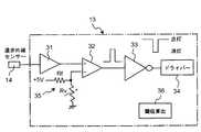
図1および2に示すように、この第1実施形態の画像表示装置は、例えば、右目用のヘッドマウントディスプレイ装置や眼鏡型ディスプレイ装置であって、画像表示部の一例としての液晶ディスプレイ(LCD)11と、この液晶ディスプレイ11のバックライト12と、このバックライト12の消灯制御を行う制御装置13とを備えている。上記液晶ディスプレイ11は、図1に示すように、目本体2の目線の先に配置しており、上記目本体2の目線は水平である。 As shown in FIGS. 1 and 2, the image display device according to the first embodiment is, for example, a right-eye head-mounted display device or glasses-type display device, and a liquid crystal display (LCD) as an example of an image display unit. 11, a
また、この画像表示装置は、瞼1の開閉を検出するセンサーの一例としての遠赤外線センサー14を備えている。上記遠赤外線センサー14は、上記目本体2の視野の外となる斜め下方に配置している。 The image display device also includes a far-
上記遠赤外線センサー14が瞼1または目本体2からの遠赤外線15を受けて、瞼1の開閉を検出できるのは、次の理由による。 The far
図3は、上記赤外線センサー14の出力を、時間を横軸で、温度を縦軸で示したもので、1瞬きの間の出力の変化を示している。目本体2の温度は、角膜上の水分に、角膜からの遠赤外線が吸収されることと、水分の気化による放熱のため、例えば35℃となり、瞼1の温度36℃よりも低い温度である。したがって、遠赤外線センサー14は、瞼1が完全に開放されているときは、遠赤外線15により目本体2の温度35℃(以下、開温度35℃という。)を検出する一方、瞼1が完全に閉鎖されたときは、瞼1からの遠赤外線15により目本体2の開温度35℃よりも高い瞼1の温度36℃(以下、閉温度36℃という。)を検出するから、瞼1の開閉を確実に検出することができる。この赤外線センサー14は、特許文献1とは違って、目本体に光を照射するための発光素子が不要で、この発光素子を駆動する発光エネルギーが不要であるので、エネルギーの消費が少ないという利点を有する。 FIG. 3 shows the output of the
なお、図3において、Thは、後述する閾値を示している。 In FIG. 3, Th indicates a threshold value to be described later.
上記遠赤外線センサー14の出力は、上記制御装置13に入力されて、上記閾値Thに相当するレベルを上回ったときに、制御装置13は、液晶ディスプレイ11のバックライト12を消灯する。 When the output of the far-
上記制御装置13は、図4に示すように、遠赤外線センサー14の出力を受けるアンプ31と、比較手段の一例としてのコンパレータ32と、固定抵抗Rfと、可変抵抗Rvと、インバータ33と、ドライバー34と、マイクロコンピュータからなる閾値算出手段36とを備えている。上記アンプ31は、遠赤外線センサー14からの信号を受けて増幅する。上記固定抵抗Rfと可変抵抗Rvとは、一例としての閾値設定手段35を構成し、+5Vを分圧して閾値Thを設定し、この閾値Thをコンパレータ32の−端子に入力する。上記コンパレータ32は、+端子に入力されたアンプ31の出力と、固定抵抗Rfと可変抵抗Rvとの接続点の電圧である閾値Thとを比較する。上記コンパレータ32は、アンプ31の出力が閾値Thを超えると、つまり、遠赤外線センサー14からの信号が閾値Thに相当するレベルを超えると、ハイレベルの信号を出力して、インバータ33を介して、ローレベルの信号をドライバー34に出力して、液晶ディスプレイ11のバックライト12を消灯する。 As shown in FIG. 4, the
上記閾値設定手段35の可変抵抗Rvによって設定される閾値Thは、上記閾値算出手段36によって算出される。上記閾値算出手段36は、マイクロコンピュータのソフトウェアによって構成される。 The threshold value Th set by the variable resistor Rv of the threshold value setting means 35 is calculated by the threshold value calculation means 36. The threshold value calculation means 36 is constituted by microcomputer software.
ところで、同じ観察者でも室温、時間、体調により瞼1の開閉時の遠赤外線センサー14によって検出される温度が異なるため、閾値Thの算出、設定が重要である。 By the way, even for the same observer, the temperature detected by the far-
上記閾値算出手段36の構成、動作を、図3,5〜9を参照しながら、説明する。 The configuration and operation of the threshold calculation means 36 will be described with reference to FIGS.
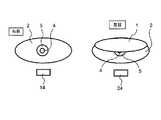
図5は、瞼1が全開状態で最大限に露出した目本体2を示す図であり、図6は、瞼1が視野を隠すまで降りた状態を示す図である。図5,6において、4は瞳孔、5は虹彩である。図7は、閾値算出手段36の動作を示すフローチャートであり、図8は遠赤外線センサー14の出力波形を示し、図9は、視線中央マーカー21と視野マーカー22が表示された液晶ディスプレイ11の画面を示している。 FIG. 5 is a view showing the eye
まず、図7に示すステップS1で、バックライト12を点灯し、後述の閾値Thが算出されて記憶されるまでバックライト12を点灯し続ける。 First, in step S1 shown in FIG. 7, the
次に、ステップS2で、遠赤外線センサー14によって、図8に示す目本体2の開温度A1,A2,A3および瞼1の閉温度B1,B2,B3を測定して、この開温度A1,A2,A3および閉温度B1,B2,B3を示すデータを閾値算出手段(マイクロコンピュータ)36のメモリに記憶する。上記データを得るために、図示しないが、遠赤外線センサー14の出力を増幅し、A/D変換(アナログディジタル変換)し、極値を求めている。Next, in step S2, the open temperatures A1 , A2 , A3 of the
次に、ステップS3で、開温度A1,A2,A3の3点平均値Aa=(A1+A2+A3)/3と、閉温度B1,B2,B3の3点平均値Ba=(B1+B2+B3)/3とを算出して、測定値のバラツキの影響を軽減する。Next, in step S3, the three-point average value Aa = (A1 + A2 + A3) / 3 of the open temperatures A1 , A2 , A3 and the three-point average value of the closing temperatures B1 , B2 , B3 Ba = (B1 + B2 + B3) / 3 is calculated to reduce the influence of variation in the measured value.
図5に示すように、瞼1が降りないで、目本体2が全開の状態の遠赤外線センサー14の検出温度は、略、図8の開温度A1,A2,A3に相当する。また、図示しないが、瞼1が図5の目本体2を完全に塞いだ状態は、図8の閉温度B1,B2,B3に相当する。したがって、閉温度B1,B2,B3の平均値Baと開温度A1,A2,A3の平均値Aaとの差(Ba−Aa)を、図5の寸法Oに対応させることができる。一方、図6に示すように、瞼1が寸法Sだけ降りたときに、目本体2の視野の全てが瞼1で隠されるとすると、求めるべき閾値Thは、
閾値Th=Aa+(Ba−Aa)xS/O
となる。As shown in FIG. 5, the detection temperature of the far-
Threshold Th = Aa + (Ba−Aa) xS / O
It becomes.
このS/Oは、正確には、人により異なるため、ステップS4で、次のようにして求める。まず、図9に示すように、液晶ディスプレイ11の画面に、視線中央マーカー21と視野マーカー22を表示し、観察者が視線中央マーカー21を凝視している状態で、視野マーカー22を徐々に下方に移動して、視野マーカー22が視野から外れて、視野マーカー22を観察者が視認できなくなったとき、そのときの視野マーカー22の位置が上述のSに対応する視野の下限に対応することになる。観察者は、視野マーカー22を視認できなくなったとき、図示しない操作部を操作し、これにより、視野マーカー22を観察者が視認できなくなったときの視野マーカー22の位置が特定される。そうすると、閾値算出手段36は、予め、視野マーカー22の位置(あるいは視線中央マーカー21と視野マーカー22との間の距離)とSとを対応づけて記憶しているメモリを参照して、Sを読み出し、予め記憶しているOを読み出して、S/Oを算出する。尤も、視野マーカー22の位置とS/Oとを対応つけて、記憶しておき、このS/Oを読み出すようにしてもよい。 Since this S / O differs from person to person, it is obtained as follows in step S4. First, as shown in FIG. 9, the visual
次に、ステップS5で、上述の平均値Aa , BaとS/Oを用いて、
閾値Th =Aa+(Ba−Aa)xS/O
を算出して、記憶する。Next, in step S5, using the above average values Aa, Ba and S / O,
Threshold Th = Aa + (Ba−Aa) xS / O
Is calculated and stored.
このように、上記閾値算出手段36が閾値Thを算出して記憶すると、閾値設定手段35は、閾値算出手段36から閾値Thを表す信号を受けて、可変抵抗Rvの抵抗値を調整して、コンパレータ32の−端子の入力信号を、閾値Thに設定する。 As described above, when the threshold
上記構成の画像表示装置において、遠赤外線センサー14は、瞼1の開閉に応じて、目本体2また瞼1の温度を検出する。 In the image display device having the above configuration, the far-
今、瞼1が図2または6に示すように、視野の全てを塞ぐ程度よりも大きく閉じ、つまり、瞼1が図6のSよりも大きく下降したとする。そうすると、遠赤外線センサー14からの信号のレベルは、図3に示す閾値Thよりも高いレベルになる。 Now, as shown in FIG. 2 or 6, it is assumed that the
上記遠赤外線センサー14からの信号は、制御装置13に入力されて、図4に示すアンプ31を介して、コンパレータ32の+端子に入力され、一方、コンパレータ32の−端子には閾値設定手段35によって閾値Thが入力されている。コンパレータ32の+端子に入力される信号のレベルは、閾値Thのレベルよりも高いから、コンパレータ32からハイレベルの信号が出力されて、インバータ33を介して、ドライバー34にローレベルの信号が入力されて、ドライバー34は、バックライト12を消灯する。 The signal from the far-
このように、覚醒時において、瞼1が視野の全てを塞ぐよりも大きく閉じたときに、直ちに、バックライト12を消灯するので、無駄に電力を消費することがなくて省電力化を達成できる。 In this way, at the time of awakening, the
一方、瞼1が、図1に示すように、開放し、あるいは、視野の全てを未だ塞いでいないときは、遠赤外線センサー14からの信号のレベルは、図3に示す閾値Thよりも低いレベルになる。 On the other hand, as shown in FIG. 1, when the
上記遠赤外線センサー14からの信号は、図4に示すアンプ31を介して、コンパレータ32の+端子に入力され、一方、コンパレータ32の−端子には閾値設定手段35によって閾値Thが入力されている。コンパレータ32の+端子に入力される信号のレベルは、閾値Thのレベルよりも低いから、コンパレータ32からローレベルの信号が出力されて、インバータ33を介して、ドライバー34にハイレベルの信号が入力されて、ドライバー34は、バックライト12を点灯する。 The signal from the far-
このように、瞼1が視野の一部でも開いているとき、つまり、瞼1が視野の全てを塞いでいないときは、バックライト12を点灯するので、画面を見ている観察者にチラツキ等による違和感を与えることがない。 In this way, when the
この第1実施形態で、どの程度、省電力が達成されるかを、具体的に検討すると、次のようになる。 A specific study of how much power saving is achieved in the first embodiment is as follows.
瞬きの回数と時間は性別、年齢、個人差があるが、例えば、20回/分、1回の瞬き100m秒とすると(図3参照)、1分間に2秒、目本体2を閉じていることになり、2秒/60秒から、液晶ディスプレイ11の消費電力の最大3.3%の削減が見込める。瞼1の開閉による遠赤外線センサー14の出力は、図3に示すように、逆ノコギリ波状なので、閾値Thをどこに設定するかで、消費電力の削減量と、画面のチラツキとして認識されるかどうかが決まる。 The number and duration of blinks vary depending on gender, age, and individual. For example, if 20 blinks / minute and one blink is 100 milliseconds (see Fig. 3), the
例えば、開温度の平均値Aa=36℃、閉温度の平均値Ba=35℃、S/O=2/3とすれば、
閾値Th =Aa+(Ba−Aa)xS/O=35+ (36−35)×2/3=35.7℃
となり、図3のグラフから時間を読むと、1回の瞬き100m秒に対して消灯時間は40mSとなり、1%の省電力化が可能となる。例えば、12型の液晶ディスプレイ11だと、LED(発光ダイオード)バックライトの消費電力は4Wであり、この液晶サイズのタブレット端末の充電池は例えば7V, 6600mAhなので、このエネルギーを全てLEDバックライトに使うと考えると、11.5時間の点灯時間の1%だと6分間駆動時間が延びる計算となる。For example, if the average open temperature Aa = 36 ° C., the average close temperature Ba = 35 ° C., and S / O = 2/3,
Threshold Th = Aa + (Ba−Aa) xS / O = 35 + (36−35) × 2/3 = 35.7 ℃
Thus, when the time is read from the graph of FIG. 3, the turn-off time is 40 mS for one blink of 100 ms, and 1% of power can be saved. For example, in the case of a 12-inch
(第2実施形態)
図10〜12は、第2実施形態の画像表示装置を説明する図であり、この第2実施形態の画像表示装置は、右目で画像を見る第1実施形態の画像表示装置とは違って、右目と左目との両方の目で、画像を見る画像表示装置である。この第2実施形態において、図10,11では、液晶ディスプレイとバックライトとを図示していないが、図1,2に示す第1実施形態の液晶ディスプレイ11とバックライト12を援用する。また、第2実施形態において、第1実施形態と同じ構成要素は、第1実施形態の構成要素と同じ参照番号を付して、詳しい説明は、省略する。(Second Embodiment)
FIGS. 10-12 is a figure explaining the image display apparatus of 2nd Embodiment, The image display apparatus of this 2nd Embodiment differs from the image display apparatus of 1st Embodiment which looks at an image with a right eye, This is an image display device in which an image is viewed with both the right eye and the left eye. In the second embodiment, the liquid crystal display and the backlight are not shown in FIGS. 10 and 11, but the
この第2実施形態の画像表示装置は、図10に示すように、右目用の遠赤外線センサー14と左目用の遠赤外線センサー24を備えている。上記右目用の遠赤外線センサー14と左目用の遠赤外線センサー24とからの信号は、図11に示す制御装置53に入力している。 As shown in FIG. 10, the image display apparatus according to the second embodiment includes a far-
上記制御装置53は、アンプ31,51と、比較手段の一例としてのコンパレータ32,52と、固定抵抗Rfと、可変抵抗Rvと、インバータ33と、ドライバー34と、右目用の閾値算出手段36と、左目用の閾値算出手段56と、アンド回路58とを備えている。 The
上記アンプ31、コンパレータ32、インバータ33、ドライバー34、右目用の閾値設定手段35および右目用の閾値算出手段36は、第1実施形態のアンプ31、コンパレータ32、固定抵抗Rf、可変抵抗Rv、インバータ33、ドライバー34、閾値設定手段35および閾値算出手段36と同一構成なので、それらと同一参照番号を付して詳しい説明は省略する。 The
また、左目用の閾値算出手段56は、左目用の遠赤外線センサー24からの信号に基づいて、閾値を算出する点のみが、右目用の閾値算出手段36と異なるので、その構成、動作の説明は図7を援用して省略する。また、左目用の閾値設定手段55の構成、作用は、右目用の閾値設定手段35の構成、作用と同様である。 Further, the threshold value calculation means 56 for the left eye is different from the threshold value calculation means 36 for the right eye only in that the threshold value is calculated based on the signal from the far-
上記アンプ51は、左目用の遠赤外線センサー24からの信号を受けて増幅して、コンパレータ52の+端子に入力する。このコンパレータ52の−端子には、固定抵抗Rfと可変抵抗Rvとからなる閾値設定手段55で設定された閾値Thが入力される。 The
上記コンパレータ32,52の出力は、アンド回路58に入力されて、論理積がとられる。したがって、右目用の遠赤外線センサー14と左目用の遠赤外線センサー24との両方から、閾値Thのレベルを超える信号が、アンプ31,51を介して、コンパレータ32,52の+端子に入力されると、アンド回路58から、図12に示す期間Tの間、ハイレベルの信号が出力される。そして、このハイレベルの信号は、インバータ33によって、ローレベルになって、ドライバー34に入力されて、バックライト12が消灯される。 The outputs of the
なお、図12では、説明の便宜上、左目用の閾値と右目用の閾値が同一であるとしているが、異なっていてもよいのは勿論である。 In FIG. 12, for convenience of explanation, the left-eye threshold and the right-eye threshold are the same, but of course they may be different.
このように、第2実施形態では、アンド回路58で論理積をとって、右目の瞼1と左目の瞼1とが、図12に示すように、同時に閾値Thを超えるだけ閉じられた期間Tだけ、バックライト12を消灯するようにしているので、片目だけに画像が入らないということがない。したがって、瞼が特殊な動きをするチック症の患者でも、チラツキを認識することがない。 As described above, in the second embodiment, the AND
第1および第2実施形態では、閾値算出手段36,56を設けているが、この閾値算出手段36,56は設けなくてもよい。例えば、閾値設定手段で、殆どの観察者に適用できる閾値を地域、人種等に応じて固定的に設定してもよく、あるいは、複数の閾値を用意して、観察者がチラツキを感じない閾値を適宜選択して設定するようにしてもよい。 In the first and second embodiments, the threshold calculation means 36 and 56 are provided, but the threshold calculation means 36 and 56 may not be provided. For example, the threshold setting means may set a threshold that can be applied to most observers according to the region, race, etc., or a plurality of thresholds may be prepared so that the observer does not feel flickering. The threshold value may be appropriately selected and set.
また、閾値設定手段は、並列に接続された複数の抵抗を、スイッチで選択して、閾値を設定するようにしてもよい。 The threshold setting means may select a plurality of resistors connected in parallel with a switch and set the threshold.
また、第1および第2実施形態では、瞼の開閉を検出するセンサーとして、遠赤外線センサーを用いたが、これに限らないことは勿論である。例えば、瞼の開閉を検出するセンサーとして、発光素子と撮像素子とを用いるセンサー(特開平9−105853号公報参照)や、網膜の電位を検出して瞼の開閉を検出するセンサー(特開2011−87609号公報参照)を用いてもよい。 In the first and second embodiments, the far-infrared sensor is used as the sensor for detecting the opening / closing of the bag. However, the present invention is not limited to this. For example, as a sensor for detecting the opening / closing of the eyelid, a sensor using a light emitting element and an image sensor (see Japanese Patent Application Laid-Open No. 9-105853), or a sensor for detecting the opening / closing of the eyelid by detecting the potential of the retina (Japanese Patent Application Laid-Open No. 2011-2011). -87609) may be used.
また、第1および第2実施形態では、画像表示部として、液晶ディスプレイを用いたが、自発光ディスプレイ(例えば、プラズマディスプレイ,有機EL(Electro Luminescence),SED(Surface Condition Electron Emitter Display)等)を用いてもよい。 In the first and second embodiments, a liquid crystal display is used as the image display unit. However, a self-luminous display (for example, a plasma display, an organic EL (Electro Luminescence), a SED (Surface Condition Electron Emitter Display), etc.) is used. It may be used.
また、画像表示装置において、本体(枠体)、バンド、ケーブル、スピーカ等は、特許文献1等で、種々のものが周知で、また、それらは、この発明の要旨とは関係がないので、それらの説明は、第1および第2実施形態では、省略している。 Further, in the image display device, the main body (frame body), the band, the cable, the speaker, and the like are variously known in
1 瞼
2 目本体
11 液晶ディスプレイ
12 バックライト
13,53 制御装置
14,24 遠赤外線センサー
32,52 コンパレータ
34 ドライバー
35,55 閾値設定手段
36,56 閾値算出手段
58 アンド回路DESCRIPTION OF
Claims (5)
Translated fromJapanese上記画像表示部を観察している観察者の覚醒状態の瞬きによる瞼の開閉動作を検出するセンサーと、
上記センサーからの信号を受けて、上記観察者の瞼が予め定められた一定値以上閉じられ、かつ、上記瞼が上記覚醒状態の瞬きによって観察者の視野の全てを塞ぐよりも大きく閉じたときに、直ちに、上記画像表示部を消灯するように制御する制御装置と
を備えることを特徴とする画像表示装置。An image display unit;
A sensor for detecting the opening / closing operationof the eyelidby blinking ofthe awakening state of the observer observing the image display unit;
When the signal from the sensor is received and the observer's eyelid is closed more than a predetermined value, and the eyelid closes more than the eyebrows closes all of the observer's visual field And a control device for controlling the image display unit to be turned offimmediately .
上記センサーは、観察者の左目の瞼の開閉動作を検出する左目用のセンサーと観察者の右目の瞼の開閉動作を検出する右目用のセンサーとを含み、
上記制御装置は、上記左目用および右目用のセンサーからの信号に基づいて、上記観察者の左目および右目の両方の瞼が予め定められた一定値以上閉じられているときに、上記画像表示部を消灯するように制御する
ことを特徴とする画像表示装置。The image display device according to claim 1,
The sensor includes a sensor for the left eye that detects the opening / closing operation of the eyelid of the left eye of the observer and a sensor for the right eye that detects the opening / closing operation of the eyelid of the right eye of the observer,
The control device, when the eyelids of both the left eye and the right eye of the observer are closed by a predetermined value or more based on signals from the left-eye and right-eye sensors, the image display unit An image display device that is controlled to be turned off.
上記センサーは、瞼と目本体の温度差を検出可能な遠赤外線センサーであることを特徴とする画像表示装置。The image display device according to claim 1 or 2,
The image display device, wherein the sensor is a far-infrared sensor capable of detecting a temperature difference between the eyelid and the eye body.
上記制御装置は、
瞼の閉を判別するための閾値を設定する閾値設定手段と、
上記センサーからの信号と上記閾値とを比較する比較手段と
を備えて、上記比較手段からの信号に基づいて、上記画像表示部を消灯制御することを特徴とする画像表示装置。In the image display device according to any one of claims 1 to 3,
The control device
Threshold setting means for setting a threshold for determining whether the bag is closed;
An image display apparatus comprising: a comparison unit that compares a signal from the sensor and the threshold value, and controls the image display unit to be turned off based on the signal from the comparison unit.
上記制御装置は、
上記センサーからの信号に基づいて、瞼の閉を判別するための閾値を算出する閾値算出手段
を備えて、
上記比較手段によって、上記センサーからの信号と上記閾値とを比較し、上記比較手段からの信号に基づいて、上記画像表示部を消灯制御することを特徴とする画像表示装置。The image display device according to claim 4,
The control device
Based on a signal from the sensor, a threshold value calculating means for calculating a threshold value for determining whether the bag is closed,
An image display device characterized in that the comparison means compares the signal from the sensor with the threshold value, and controls the image display unit to be turned off based on the signal from the comparison means.
Priority Applications (4)
| Application Number | Priority Date | Filing Date | Title |
|---|---|---|---|
| JP2012024249AJP5936379B2 (en) | 2012-02-07 | 2012-02-07 | Image display device |
| PCT/JP2012/081690WO2013118379A1 (en) | 2012-02-07 | 2012-12-06 | Image display device |
| CN201280069135.2ACN104094591B (en) | 2012-02-07 | 2012-12-06 | Image display device |
| US14/374,134US20150029096A1 (en) | 2012-02-07 | 2012-12-06 | Image display device |
Applications Claiming Priority (1)
| Application Number | Priority Date | Filing Date | Title |
|---|---|---|---|
| JP2012024249AJP5936379B2 (en) | 2012-02-07 | 2012-02-07 | Image display device |
Publications (2)
| Publication Number | Publication Date |
|---|---|
| JP2013162407A JP2013162407A (en) | 2013-08-19 |
| JP5936379B2true JP5936379B2 (en) | 2016-06-22 |
Family
ID=48947166
Family Applications (1)
| Application Number | Title | Priority Date | Filing Date |
|---|---|---|---|
| JP2012024249AExpired - Fee RelatedJP5936379B2 (en) | 2012-02-07 | 2012-02-07 | Image display device |
Country Status (4)
| Country | Link |
|---|---|
| US (1) | US20150029096A1 (en) |
| JP (1) | JP5936379B2 (en) |
| CN (1) | CN104094591B (en) |
| WO (1) | WO2013118379A1 (en) |
Families Citing this family (45)
| Publication number | Priority date | Publication date | Assignee | Title |
|---|---|---|---|---|
| US9599981B2 (en) | 2010-02-04 | 2017-03-21 | Echostar Uk Holdings Limited | Electronic appliance status notification via a home entertainment system |
| KR102087967B1 (en)* | 2013-07-30 | 2020-04-16 | 삼성디스플레이 주식회사 | Liquid crystal display and driving method thereof |
| US20150161452A1 (en) | 2013-12-11 | 2015-06-11 | Echostar Technologies, Llc | Home Monitoring and Control |
| US9900177B2 (en) | 2013-12-11 | 2018-02-20 | Echostar Technologies International Corporation | Maintaining up-to-date home automation models |
| US9769522B2 (en) | 2013-12-16 | 2017-09-19 | Echostar Technologies L.L.C. | Methods and systems for location specific operations |
| US9723393B2 (en)* | 2014-03-28 | 2017-08-01 | Echostar Technologies L.L.C. | Methods to conserve remote batteries |
| KR101709087B1 (en)* | 2014-08-01 | 2017-02-23 | 삼성디스플레이 주식회사 | Timing controller, display and driving method for the same |
| US9621959B2 (en) | 2014-08-27 | 2017-04-11 | Echostar Uk Holdings Limited | In-residence track and alert |
| US9824578B2 (en) | 2014-09-03 | 2017-11-21 | Echostar Technologies International Corporation | Home automation control using context sensitive menus |
| US9699436B2 (en)* | 2014-09-16 | 2017-07-04 | Microsoft Technology Licensing, Llc | Display with eye-discomfort reduction |
| US9989507B2 (en) | 2014-09-25 | 2018-06-05 | Echostar Technologies International Corporation | Detection and prevention of toxic gas |
| US9983011B2 (en) | 2014-10-30 | 2018-05-29 | Echostar Technologies International Corporation | Mapping and facilitating evacuation routes in emergency situations |
| US9511259B2 (en) | 2014-10-30 | 2016-12-06 | Echostar Uk Holdings Limited | Fitness overlay and incorporation for home automation system |
| CN107072524B (en)* | 2014-11-19 | 2018-11-30 | 夏普株式会社 | eye movement detection device |
| US9967614B2 (en) | 2014-12-29 | 2018-05-08 | Echostar Technologies International Corporation | Alert suspension for home automation system |
| US9729989B2 (en) | 2015-03-27 | 2017-08-08 | Echostar Technologies L.L.C. | Home automation sound detection and positioning |
| CN104834446B (en)* | 2015-05-04 | 2018-10-26 | 惠州Tcl移动通信有限公司 | A kind of display screen multi-screen control method and system based on eyeball tracking technology |
| US9946857B2 (en) | 2015-05-12 | 2018-04-17 | Echostar Technologies International Corporation | Restricted access for home automation system |
| US9948477B2 (en) | 2015-05-12 | 2018-04-17 | Echostar Technologies International Corporation | Home automation weather detection |
| US9632746B2 (en) | 2015-05-18 | 2017-04-25 | Echostar Technologies L.L.C. | Automatic muting |
| EP3109689A1 (en)* | 2015-06-22 | 2016-12-28 | Nokia Technologies Oy | Transition from a display power mode to a different display power mode |
| US9960980B2 (en) | 2015-08-21 | 2018-05-01 | Echostar Technologies International Corporation | Location monitor and device cloning |
| JP2017058853A (en)* | 2015-09-15 | 2017-03-23 | 株式会社コーエーテクモゲームス | Information processing apparatus, operation control method, and operation control program |
| KR102340938B1 (en)* | 2015-09-17 | 2021-12-20 | 엘지디스플레이 주식회사 | Display device and method of measuring contact resistance thereof |
| US9996066B2 (en) | 2015-11-25 | 2018-06-12 | Echostar Technologies International Corporation | System and method for HVAC health monitoring using a television receiver |
| US10101717B2 (en) | 2015-12-15 | 2018-10-16 | Echostar Technologies International Corporation | Home automation data storage system and methods |
| US9798309B2 (en) | 2015-12-18 | 2017-10-24 | Echostar Technologies International Corporation | Home automation control based on individual profiling using audio sensor data |
| US10229540B2 (en) | 2015-12-22 | 2019-03-12 | Google Llc | Adjusting video rendering rate of virtual reality content and processing of a stereoscopic image |
| US10091017B2 (en) | 2015-12-30 | 2018-10-02 | Echostar Technologies International Corporation | Personalized home automation control based on individualized profiling |
| US10073428B2 (en) | 2015-12-31 | 2018-09-11 | Echostar Technologies International Corporation | Methods and systems for control of home automation activity based on user characteristics |
| US10060644B2 (en) | 2015-12-31 | 2018-08-28 | Echostar Technologies International Corporation | Methods and systems for control of home automation activity based on user preferences |
| US9628286B1 (en) | 2016-02-23 | 2017-04-18 | Echostar Technologies L.L.C. | Television receiver and home automation system and methods to associate data with nearby people |
| AU2017225977C1 (en)* | 2016-03-04 | 2023-08-03 | Magic Leap, Inc. | Current drain reduction in AR/VR display systems |
| US10698215B2 (en) | 2016-03-25 | 2020-06-30 | Magic Leap, Inc. | Virtual and augmented reality systems and methods |
| US9882736B2 (en) | 2016-06-09 | 2018-01-30 | Echostar Technologies International Corporation | Remote sound generation for a home automation system |
| US10294600B2 (en) | 2016-08-05 | 2019-05-21 | Echostar Technologies International Corporation | Remote detection of washer/dryer operation/fault condition |
| US10049515B2 (en) | 2016-08-24 | 2018-08-14 | Echostar Technologies International Corporation | Trusted user identification and management for home automation systems |
| CN106406501A (en)* | 2016-09-30 | 2017-02-15 | 珠海市魅族科技有限公司 | Method and device for controlling rendering |
| GB2562528B (en) | 2017-05-18 | 2022-02-02 | Advanced Risc Mach Ltd | Devices, methods, computer programs, processors and headsets |
| US10802585B2 (en) | 2018-07-12 | 2020-10-13 | Apple Inc. | Electronic devices with display operation based on eye activity |
| US11966055B2 (en) | 2018-07-19 | 2024-04-23 | Magic Leap, Inc. | Content interaction driven by eye metrics |
| US20200073465A1 (en)* | 2018-08-30 | 2020-03-05 | Qualcomm Incorporated | Load reduction in a visual rendering system |
| TWI783163B (en)* | 2019-08-19 | 2022-11-11 | 緯創資通股份有限公司 | Power control device, computer system and related power control method |
| JP7693402B2 (en) | 2021-06-08 | 2025-06-17 | キヤノン株式会社 | Display device, imaging device, display device control method, program, and recording medium |
| KR20230131349A (en)* | 2022-03-03 | 2023-09-13 | 삼성디스플레이 주식회사 | Display device |
Family Cites Families (12)
| Publication number | Priority date | Publication date | Assignee | Title |
|---|---|---|---|---|
| JPH04212331A (en)* | 1990-06-21 | 1992-08-03 | Mitsubishi Denki Eng Kk | Sleep detector |
| JPH05328256A (en)* | 1992-05-26 | 1993-12-10 | Olympus Optical Co Ltd | Head mount type display device |
| JPH11249064A (en)* | 1998-03-04 | 1999-09-17 | Omron Corp | Head mounted display device |
| US6087941A (en)* | 1998-09-01 | 2000-07-11 | Ferraz; Mark | Warning device for alerting a person falling asleep |
| JP2000121991A (en)* | 1998-10-15 | 2000-04-28 | Matsushita Electric Works Ltd | Hood type display device |
| US7027621B1 (en)* | 2001-03-15 | 2006-04-11 | Mikos, Ltd. | Method and apparatus for operator condition monitoring and assessment |
| US7091471B2 (en)* | 2004-03-15 | 2006-08-15 | Agilent Technologies, Inc. | Using eye detection for providing control and power management of electronic devices |
| JP4284538B2 (en)* | 2004-10-19 | 2009-06-24 | ソニー株式会社 | Playback apparatus and playback method |
| JP2007127716A (en)* | 2005-11-01 | 2007-05-24 | Pioneer Electronic Corp | Display apparatus, display method, display program, and computer-readable recording medium |
| US20090243966A1 (en)* | 2006-07-25 | 2009-10-01 | Nikon Corporation | Outputting apparatus and image display apparatus |
| JP5212155B2 (en)* | 2009-02-10 | 2013-06-19 | ブラザー工業株式会社 | Head mounted display |
| US9766698B2 (en)* | 2011-05-05 | 2017-09-19 | Nokia Technologies Oy | Methods and apparatuses for defining the active channel in a stereoscopic view by using eye tracking |
- 2012
- 2012-02-07JPJP2012024249Apatent/JP5936379B2/ennot_activeExpired - Fee Related
- 2012-12-06CNCN201280069135.2Apatent/CN104094591B/ennot_activeExpired - Fee Related
- 2012-12-06USUS14/374,134patent/US20150029096A1/ennot_activeAbandoned
- 2012-12-06WOPCT/JP2012/081690patent/WO2013118379A1/enactiveApplication Filing
Also Published As
| Publication number | Publication date |
|---|---|
| US20150029096A1 (en) | 2015-01-29 |
| CN104094591B (en) | 2017-08-08 |
| JP2013162407A (en) | 2013-08-19 |
| CN104094591A (en) | 2014-10-08 |
| WO2013118379A1 (en) | 2013-08-15 |
Similar Documents
| Publication | Publication Date | Title |
|---|---|---|
| JP5936379B2 (en) | Image display device | |
| US12038629B1 (en) | Personalized optics | |
| RU2644265C2 (en) | Imaging device and device for entering information | |
| US10962808B2 (en) | Contact lens with image pickup control | |
| US11707595B2 (en) | Controlling light exposure for circadian phase management | |
| TWI486630B (en) | Method for adjusting head mounted display adaptively and head-mounted display | |
| CN107526165B (en) | Head-mounted personal multimedia system, visual auxiliary device and related glasses | |
| CN106169290B (en) | Control method, control device and electronic device | |
| CN111095077A (en) | Electronic device with adaptive display | |
| JP2019508771A (en) | Method for operating a motor vehicle having a condition monitoring device, driver support system, and motor vehicle | |
| IL291915B2 (en) | Current drain reduction in ar/vr display systems | |
| US20150116207A1 (en) | Electronic device and control method for screen thereof | |
| CN104076510A (en) | Method for adaptively adjusting head-mounted display and head-mounted display | |
| US12210230B1 (en) | Personalized optics | |
| CN105931614B (en) | Control method, control device, and electronic device | |
| CN203250240U (en) | Computer monitor capable of protecting eyesight | |
| US11314327B2 (en) | Head mounted display and control method thereof | |
| KR20240027160A (en) | A method for adapting the sensorial output mode of a sensorial output device to a user | |
| CN106201414B (en) | Control method, control device and electronic device | |
| CN108810433B (en) | Can reduce intelligent TV set of eye injury | |
| CN110200745A (en) | Eyeshade and sleep promotion method | |
| JP2007003618A (en) | Display device and portable terminal device | |
| CN104965636A (en) | Light intensity reminding method and terminal device | |
| US20250124829A1 (en) | Head-mounted display device and method for controlling the same | |
| CN207457605U (en) | visual display device |
Legal Events
| Date | Code | Title | Description |
|---|---|---|---|
| A621 | Written request for application examination | Free format text:JAPANESE INTERMEDIATE CODE: A621 Effective date:20141001 | |
| A131 | Notification of reasons for refusal | Free format text:JAPANESE INTERMEDIATE CODE: A131 Effective date:20150929 | |
| A521 | Request for written amendment filed | Free format text:JAPANESE INTERMEDIATE CODE: A523 Effective date:20151125 | |
| TRDD | Decision of grant or rejection written | ||
| A01 | Written decision to grant a patent or to grant a registration (utility model) | Free format text:JAPANESE INTERMEDIATE CODE: A01 Effective date:20160412 | |
| A61 | First payment of annual fees (during grant procedure) | Free format text:JAPANESE INTERMEDIATE CODE: A61 Effective date:20160510 | |
| R150 | Certificate of patent or registration of utility model | Ref document number:5936379 Country of ref document:JP Free format text:JAPANESE INTERMEDIATE CODE: R150 | |
| LAPS | Cancellation because of no payment of annual fees |