JP5936359B2 - Electric vehicle charging equipment - Google Patents
Electric vehicle charging equipmentDownload PDFInfo
- Publication number
- JP5936359B2 JP5936359B2JP2012001786AJP2012001786AJP5936359B2JP 5936359 B2JP5936359 B2JP 5936359B2JP 2012001786 AJP2012001786 AJP 2012001786AJP 2012001786 AJP2012001786 AJP 2012001786AJP 5936359 B2JP5936359 B2JP 5936359B2
- Authority
- JP
- Japan
- Prior art keywords
- power
- converter
- storage battery
- charging
- battery
- Prior art date
- Legal status (The legal status is an assumption and is not a legal conclusion. Google has not performed a legal analysis and makes no representation as to the accuracy of the status listed.)
- Active
Links
- 238000005516engineering processMethods0.000description5
- 230000005611electricityEffects0.000description4
- 238000006243chemical reactionMethods0.000description2
- 238000010586diagramMethods0.000description2
- 238000007599dischargingMethods0.000description2
- 230000006866deteriorationEffects0.000description1
- 238000004519manufacturing processMethods0.000description1
- 238000010792warmingMethods0.000description1
Images

Classifications
- Y—GENERAL TAGGING OF NEW TECHNOLOGICAL DEVELOPMENTS; GENERAL TAGGING OF CROSS-SECTIONAL TECHNOLOGIES SPANNING OVER SEVERAL SECTIONS OF THE IPC; TECHNICAL SUBJECTS COVERED BY FORMER USPC CROSS-REFERENCE ART COLLECTIONS [XRACs] AND DIGESTS
- Y02—TECHNOLOGIES OR APPLICATIONS FOR MITIGATION OR ADAPTATION AGAINST CLIMATE CHANGE
- Y02E—REDUCTION OF GREENHOUSE GAS [GHG] EMISSIONS, RELATED TO ENERGY GENERATION, TRANSMISSION OR DISTRIBUTION
- Y02E60/00—Enabling technologies; Technologies with a potential or indirect contribution to GHG emissions mitigation
- Y02E60/10—Energy storage using batteries
- Y—GENERAL TAGGING OF NEW TECHNOLOGICAL DEVELOPMENTS; GENERAL TAGGING OF CROSS-SECTIONAL TECHNOLOGIES SPANNING OVER SEVERAL SECTIONS OF THE IPC; TECHNICAL SUBJECTS COVERED BY FORMER USPC CROSS-REFERENCE ART COLLECTIONS [XRACs] AND DIGESTS
- Y02—TECHNOLOGIES OR APPLICATIONS FOR MITIGATION OR ADAPTATION AGAINST CLIMATE CHANGE
- Y02T—CLIMATE CHANGE MITIGATION TECHNOLOGIES RELATED TO TRANSPORTATION
- Y02T10/00—Road transport of goods or passengers
- Y02T10/60—Other road transportation technologies with climate change mitigation effect
- Y02T10/70—Energy storage systems for electromobility, e.g. batteries
- Y—GENERAL TAGGING OF NEW TECHNOLOGICAL DEVELOPMENTS; GENERAL TAGGING OF CROSS-SECTIONAL TECHNOLOGIES SPANNING OVER SEVERAL SECTIONS OF THE IPC; TECHNICAL SUBJECTS COVERED BY FORMER USPC CROSS-REFERENCE ART COLLECTIONS [XRACs] AND DIGESTS
- Y02—TECHNOLOGIES OR APPLICATIONS FOR MITIGATION OR ADAPTATION AGAINST CLIMATE CHANGE
- Y02T—CLIMATE CHANGE MITIGATION TECHNOLOGIES RELATED TO TRANSPORTATION
- Y02T10/00—Road transport of goods or passengers
- Y02T10/60—Other road transportation technologies with climate change mitigation effect
- Y02T10/72—Electric energy management in electromobility
Landscapes
- Charge And Discharge Circuits For Batteries Or The Like (AREA)
- Secondary Cells (AREA)
- Electric Propulsion And Braking For Vehicles (AREA)
Description
Translated fromJapanese本発明は、電気自動車用充電設備について、電気自動車用充電設備に備える蓄電池の容量低減と部品故障率の低減ができるように工夫したものである。The present invention relates to havecharging facilities Nitsu for electric vehicles, in which reduction of the capacitance reducing the component failure rate of the battery provided in an electric vehicle charging equipment was devised as possible.
エネルギー制約の高まりや地球温暖化対策の観点から、エネルギー効率が高くCO2排出量が少ない電気自動車が注目されている。電気自動車には、駆動源となるモータと、電源となる車載バッテリと、モータ制御装置等が備えられている。電気自動車は、モータ制御装置により、モータに供給する電力を制御することによって走行する。
このような電気自動車の車載バッテリは、外部電力で充電することが必要であるため、充電設備を必要とする。From the viewpoint of increasing energy constraints and countermeasures against global warming, electric vehicles with high energy efficiency and low CO2 emissions are attracting attention. An electric vehicle includes a motor as a drive source, an in-vehicle battery as a power source, a motor control device, and the like. The electric vehicle travels by controlling electric power supplied to the motor by a motor control device.
Such an in-vehicle battery for an electric vehicle needs to be charged with external power, and thus requires a charging facility.
充電設備は、交流の商用系統電源から交流電力を取り込み、この交流電力を直流電力に変換し、変換した直流電力を電気自動車の車載バッテリに給電して充電を行う。 The charging facility takes in AC power from an AC commercial power supply, converts the AC power into DC power, and supplies the converted DC power to an in-vehicle battery of the electric vehicle for charging.
充電器としては、一般家庭用電源と同じ交流電源(単相100V、あるいは単相200V)を用いて長時間(例えば約7〜21時間)をかけて充電する普通充電器と、高い電力(例えば30〜50kW)を用いて短時間(例えば約15〜30分)で充電をする急速充電器とがある。 As a charger, a normal charger that charges over a long period of time (for example, about 7 to 21 hours) using the same AC power source (single-phase 100 V or single-phase 200 V) as a general household power source, and high power (for example, There is a quick charger that charges in a short time (for example, about 15 to 30 minutes) using 30 to 50 kW).
普通充電器では、低容量の受電契約でも設置できるが、充電に時間を要する。
一方、急速充電器では、大容量の受電契約が必要であるが、短時間で充電ができる。A normal charger can be installed even with a low-capacity power reception contract, but it takes time to charge.
On the other hand, a quick charger requires a large-capacity power reception contract, but can be charged in a short time.
電気自動車の普及に伴い、短時間での充電ニーズに対応するため、急速充電器のインフラを整える必要があると考えられる。
そこで、商用系統電源側に対する負荷の平準化を図りながら、急速充電することができる急速充電設備が開発され、特許出願がされている。With the widespread use of electric vehicles, it is considered necessary to prepare an infrastructure for quick chargers in order to meet charging needs in a short time.
Therefore, a quick charging facility capable of rapid charging while leveling the load on the commercial system power supply side has been developed and a patent application has been filed.
ここで、図2を参照して、商用系統電源側に対する負荷の平準化を図りながら急速充電をすることができる、先に出願されている従来の急速充電設備の一例を説明する。 Here, with reference to FIG. 2, an example of a conventional quick charging facility that has been filed earlier and that can perform quick charging while leveling the load on the commercial power supply side will be described.
図2に示す電気自動車用充電設備10は、電気自動車1に搭載されている車載バッテリ2を急速充電する充電設備である。
この電気自動車用充電設備10は、整流器11と、スイッチ12と、DC/DCコンバータ13と、スイッチ14と、設備蓄電池15を主要部材として有している。An electric
The electric
電気自動車用充電設備10の整流器11は、交流の商用系統電源3から交流電力を取り込み、取り込んだ交流電力を直流電力に変換して出力する。 The
DC/DCコンバータ13は、設備蓄電池15の充電をする設備蓄電池充電モードでは、入力される直流電力の電圧を、設備蓄電池15を充電するのに適した電圧に変換して直流電力を出力し、一方、車載バッテリ2の充電をする車載バッテリ充電モードでは、入力される直流電力の電圧を、車載バッテリ2を充電するのに適した電圧に変換して直流電力を出力する。 In the equipment storage battery charging mode in which the
スイッチ12及びスイッチ14は、制御装置(図示省略)の制御に基づき、設備蓄電池充電モードでは、図2において実線で示す状態のスイッチング状態に投入され、一方、車載バッテリ充電モードでは、図2において点線で示すスイッチング状態に投入される。 The
設備蓄電池充電モードでは、スイッチ12及びスイッチ14が、図2において実線で示すスイッチング状態に投入される。
そして整流器11から出力されスイッチ12を介してDC/DCコンバータ13に送られた直流電圧は、DC/DCコンバータ13により、設備蓄電池15の充電に適した直流電圧に変換される。この直流電圧の電力が、スイッチ14を介して設備蓄電池15に供給されて、設備蓄電池15の充電をすることができる。In the facility storage battery charging mode, the
The DC voltage output from the
電気自動車用充電設備10は、商用系統電源3からの買電力(受電電力)を抑えて設備蓄電池15の充電をするため、この電気自動車用充電設備10は、商用系統電源3に対して低負荷な設備となり、負荷の平準化を図ることができる。特に、電気需要の少ない深夜等において、設備蓄電池15の充電をするようにしておけば、更に負荷の平準化を促す設備になる。 Since the electric
電気自動車用充電設備10と電気自動車1との間で通信が行われて、車載バッテリ充電モードになったときには、スイッチ12及びスイッチ14が、図2において点線で示す状態のスイッチング状態に投入される。更に出力端子16に接続された充電ケーブル17が、電気自動車1の車載バッテリ2に電気的に接続される。
そして、設備蓄電池15から出力されスイッチ12を介してDC/DCコンバータ13に送られた直流電力の電圧が、DC/DCコンバータ13により、車載バッテリ2を充電するのに適した電圧に変換される。この直流電圧の電力が、出力端子16及び充電ケーブル17を介して車載バッテリ2に供給されて、車載バッテリ2の充電をすることができる。When communication is performed between the electric
The voltage of the DC power output from the
このように、設備蓄電池15に充電された電力を高出力で放電するため、車載バッテリ2を短時間で急速充電することができる。 Thus, since the electric power charged in the
ところで図2に示す従来の電気自動車用充電設備10で車載バッテリ2を急速充電する場合には、設備蓄電池15に充電された電力のみで充電をしている。つまり設備蓄電池15が車載バッテリ2への唯一の電力供給源となる機器であり、連続充電する場合は設備蓄電池15の蓄電容量に頼らざるを得ないため、設備蓄電池15としては大容量の蓄電池が必要である。
このように大容量の設備蓄電池15が必要であるため、電気自動車用充電設備10の製造コストが高くなっていた。By the way, when the vehicle-mounted
Thus, since the large-capacity
また、使用回数に伴い故障(劣化に起因する故障等)の確立が上がるスイッチを2つ使用していたため、その分だけ電気自動車用充電設備10の故障確率を上げていた。 In addition, since two switches that increase the probability of failure (failure due to deterioration, etc.) with the number of times of use are used, the failure probability of the electric
更に、整流器11から出力されて、最終的に車載バッテリ2に充電される電力について考慮すると、従来の電気自動車用充電設備10では、電力ロスが多いという問題がある。
即ち、設備蓄電池充電モードでは、DC/DCコンバータ13での変換動作により電力がロスすると共に設備蓄電池15での充電動作により電力がロスし、車載バッテリ充電モードでは、設備蓄電池15での放電動作により電力がロスすると共にDC/DCコンバータ13での変換動作により電力がロスする。
結局、従来の電気自動車用充電設備10は、従来の急速充電器と比較し、定置型の設備蓄電池15の充放電による電力ロスが発生し電気自動車への充電効率が悪かった。Furthermore, when the electric power output from the
That is, in the facility storage battery charging mode, power is lost due to the conversion operation in the DC /
As a result, the conventional electric
本発明は、上記従来技術に鑑み、蓄電池容量の低減ができ、しかも従来技術と比較して故障率が低く充電効率の高い、電気自動車用充電設備を提供することを目的とする。An object of the present invention isto provide acharging facility for an electric vehicle that can reduce the storage battery capacity and has a lower failure rate and higher charging efficiency than the conventional technology.
上記課題を解決する本発明の電気自動車用充電設備の構成は、
設備蓄電池と、
商用系統電源から交流電力を取り込んで、この交流電力を直流電力に変換するAC/DCコンバータと、
受電端子が前記AC/DCコンバータの出力端子に接続されており、受電した直流電力の電圧を制御して出力するDC/DCコンバータと、
スイッチ切替動作をすることにより、設備蓄電池充電モードでは、前記DC/DCコンバータから出力された直流電力を、前記設備蓄電池に送り、車載バッテリ充電モードでは、前記DC/DCコンバータから出力された直流電力を、電気自動車の車載バッテリに送ることを目的としたスイッチと、
アノードが前記設備蓄電池に電気的に接続され、カソードが前記AC/DCコンバータの前記出力端子及び前記DC/DCコンバータの前記受電端子に電気的に接続されたダイオードとを、有することを特徴とする。The configuration of the charging facility for electric vehicles of the present invention that solves the above problems is as follows.
Equipment storage battery,
An AC / DC converter that takes in AC power from a commercial power supply and converts this AC power into DC power;
A DC / DC converter in which a power receiving terminal is connected to an output terminal of the AC / DC converter, and controls and outputs a voltage of the received DC power;
By performing the switch switching operation, in the equipment storage battery charging mode, the DC power output from the DC / DC converter is sent to the equipment storage battery, and in the in-vehicle battery charging mode, the DC power output from the DC / DC converter. A switch intended to send the battery to the in-vehicle battery of the electric vehicle,
A diode having an anode electrically connected to the facility storage battery and a cathode electrically connected to the output terminal of the AC / DC converter and the power receiving terminal of the DC / DC converter. .
本発明によれば、車載バッテリ充電モードでは、設備蓄電池から出力された直流電力のみならず、AC/DCコンバータから出力された直流電力も加わって、車載バッテリを充電するため、設備蓄電池の容量を小さくすることができる。
また、従来技術と同容量の設備蓄電池を使用した場合、従来技術では設備蓄電池の放電電力のみで車載バッテリを充電するのに対し、本発明は設備蓄電池と商用系統電源により車載バッテリを充電できるため、車載バッテリを1回充電する際に設備蓄電池から出力される電力量を抑えることができる。この結果、連続して充電することができる電気自動車の台数を、従来技術に比べて増やすことができる。According to the present invention, in the in-vehicle battery charging mode, not only the direct-current power output from the equipment storage battery but also the direct-current power output from the AC / DC converter is added to charge the in-vehicle battery. Can be small.
In addition, when a facility storage battery having the same capacity as the conventional technology is used, the conventional technology charges the vehicle-mounted battery only with the discharge power of the facility storage battery, whereas the present invention can charge the vehicle-mounted battery with the facility storage battery and the commercial power supply. When the vehicle battery is charged once, the amount of power output from the facility storage battery can be suppressed. As a result, the number of electric vehicles that can be continuously charged can be increased as compared with the prior art.
更に、従来技術に比べて機械的に動作するスイッチの数を減らすことができるため、故障率を低減して信頼性の高い電気自動車用充電設備とすることができる。 Furthermore, since the number of mechanically operated switches can be reduced as compared with the prior art, the failure rate can be reduced and a highly reliable electric vehicle charging facility can be obtained.
また、車載バッテリを充電する際には、設備蓄電池から出力された直流電力に加え、AC/DCコンバータから出力された直流電力で充電を行うが、AC/DCコンバータから出力された直流電力は、設備蓄電池を通ることなく、車載バッテリの充電に使用されるため、設備蓄電池での充放電ロスがない。
このため、従来技術と比較して電力ロスが低減し電気自動車への充電効率が向上して省エネルギーになると共に、電気料金の節約ができる。In addition, when charging an in-vehicle battery, in addition to the DC power output from the facility storage battery, charging is performed with the DC power output from the AC / DC converter, but the DC power output from the AC / DC converter is Since it is used for charging an in-vehicle battery without passing through the equipment storage battery, there is no charge / discharge loss in the equipment storage battery.
For this reason, compared with the prior art, the power loss is reduced, the charging efficiency of the electric vehicle is improved, energy saving is achieved, and the electricity bill can be saved.
以下、本発明の実施の形態について、実施例に基づき詳細に説明する。 Hereinafter, embodiments of the present invention will be described in detail based on examples.
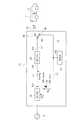
図1は、本発明の実施例に係る電気自動車用充電設備20である。この電気自動車用充電設備20は、電気自動車1に搭載されている車載バッテリ2を急速充電する充電設備である。
この電気自動車用充電設備20は、AC/DCコンバータ21と、ダイオード22と、DC/DCコンバータ23と、スイッチ24と、設備蓄電池25を主要部材として有している。FIG. 1 shows an electric
The electric
本実施例に係る電気自動車用充電設備20は、商用系統電源3からの買電力を抑えるため、低容量の電力で商用系統電源3から受電している。
この電気自動車用充電設備20のAC/DCコンバータ21は、交流の商用系統電源3から交流電力を取り込み、取り込んだ交流電力を直流電力に変換して出力する。The electric
The AC / DC
DC/DCコンバータ23は、その受電端子23iがラインL1を介して、AC/DCコンバータ21の出力端子21oに接続されている。
このDC/DCコンバータ23は、設備蓄電池25の充電をする設備蓄電池充電モードでは、受電端子23iから入力される直流電力の電圧を、設備蓄電池25を充電するのに適した電圧に変換して直流電力を出力し、一方、車載バッテリ2の充電をする車載バッテリ充電モードでは、受電端子23iから入力される直流電力の電圧を、車載バッテリ2を充電するのに適した電圧に変換して直流電力を出力する。The DC /
In the equipment storage battery charging mode in which the
スイッチ24は、ラインL2を介して、DC/DCコンバータ23の出力端子23oに接続されている。
スイッチ24は、制御装置(図示省略)の制御に基づきスイッチ切替動作をし、設備蓄電池充電モードでは、図1において実線で示すように蓄電用端子28側に投入され、一方、車載バッテリ充電モードでは、図1において点線で示すように出力端子26側に投入される。
出力端子26には充電ケーブル27が接続されており、この充電ケーブル27は電気自動車1の車載バッテリ2に電気的に接続される。
蓄電用端子28は、ラインL3を介して、蓄電池25の入出力端子25aに接続されている。The
The
A charging
The
設備蓄電池25は、その入出力端子25aがラインL4,L1を介して、AC/DCコンバータ21の出力端子21o及びDC/DCコンバータ23の受電端子23iに接続されている。
ダイオード22はラインL4に接続されている。即ち、ダイオード22は、そのアノード22aが設備蓄電池25に電気的に接続され、そのカソード22bがAC/DCコンバータ21の出力端子21o及びDC/DCコンバータ23の受電端子23iに電気的に接続されている。The
The
設備蓄電池充電モードでは、スイッチ24が、図1において実線で示すスイッチング状態、即ち蓄電用端子28側に投入される。
そしてAC/DCコンバータ21から出力されラインL1を介してDC/DCコンバータ23に送られた直流電圧は、DC/DCコンバータ23により、設備蓄電池25の充電に適した直流電圧に変換される。この直流電圧の電力が、スイッチ24及びラインL3を介して設備蓄電池25に供給されて、設備蓄電池25の充電をすることができる。In the equipment storage battery charging mode, the
The DC voltage output from the AC /
電気自動車用充電設備20は、商用系統電源3からの買電力(受電電力)を抑えて設備蓄電池25の充電をするため、この電気自動車用充電設備20は、商用系統電源3に対して低負荷な設備となり、負荷の平準化を図ることができる。特に、電気需要の少ない深夜等において、設備蓄電池25の充電をするようにしておけば、更に負荷の平準化を促す設備になる。 Since the electric
電気自動車用充電設備20と電気自動車1との間で通信が行われて、車載バッテリ充電モードになったときには、スイッチ24が、図1において点線で示す状態のスイッチング状態、即ち出力端子26側に投入される。更に出力端子26に接続された充電ケーブル27が、電気自動車1の車載バッテリ2に電気的に接続される。 When communication is performed between the electric
そして、設備蓄電池25から出力されダイオード22を介してDC/DCコンバータ23に送られた直流電力PBとAC/DCコンバータ21から出力された直流電力PGの電圧が、DC/DCコンバータ23により、車載バッテリ2を充電するのに適した電圧に変換される。この直流電圧の電力が、出力端子26及び充電ケーブル27を介して車載バッテリ2に供給されて、車載バッテリ2の充電をすることができる。Then, the voltage of the DC power PG outputted from the DC power PB and the AC /
このように、車載バッテリ2の充電を、設備蓄電池25から出力された直流電力PBとAC/DCコンバータ21から出力された直流電力PGで行うことができるため、車載バッテリ2を短時間で急速充電することができる。
しかも、設備蓄電池25から出力された直流電力PBのみならず、AC/DCコンバータ21から出力された直流電力PGも加わって、車載バッテリ2を充電するため、買電力を抑えることができ、なおかつ従来技術と比較して設備蓄電池25の容量が小さくても車載バッテリ2の急速充電をすることができる。Thus, the in-
Moreover, not only the DC power PB output from the
また、従来技術と同容量の設備蓄電池25を使用した場合、従来技術では設備蓄電池の放電電力のみで車載バッテリを充電するのに対し、本発明は設備蓄電池25と商用系統電源3により車載バッテリ2を充電できるため、車載バッテリ2を1回充電する際に設備蓄電池25から出力される電力量を抑えることができる。この結果、連続して充電することができる電気自動車の台数を、従来技術に比べて増やすことができる。 Further, when the
また、1つのスイッチ24のみを備えるため、従来技術に比べて、機械的に動作する部品点数を削減することができると共に、スイッチ切替動作に伴うスイッチ故障率が低減する。 Since only one
更に、AC/DCコンバータ21から出力された直流電力PGは、設備蓄電池25を通ることなく、車載バッテリ2の充電に使用されるため、直流電力PGについては、設備蓄電池25での充放電ロスがない。
このため、従来技術と比較して電力ロスが低減し電気自動車への充電効率が向上して省エネルギーになると共に、電気料金の節約ができる。Further, the DC power PG outputted from the AC /
For this reason, compared with the prior art, the power loss is reduced, the charging efficiency of the electric vehicle is improved, energy saving is achieved, and the electricity bill can be saved.
1 電気自動車
2 車載バッテリ
3 商用系統電源
20 電気自動車用充電設備
21 AC/DCコンバータ
22 ダイオード
23 DC/DCコンバータ
24 スイッチ
25 設備蓄電池
26 出力端子
27 充電ケーブル
28 蓄電用端子DESCRIPTION OF SYMBOLS 1
Claims (1)
Translated fromJapanese商用系統電源から交流電力を取り込んで、この交流電力を直流電力に変換するAC/DCコンバータと、
受電端子が前記AC/DCコンバータの出力端子に接続されており、受電した直流電力の電圧を制御して出力するDC/DCコンバータと、
スイッチ切替動作をすることにより、設備蓄電池充電モードでは、前記DC/DCコンバータから出力された直流電力を、前記設備蓄電池に送り、車載バッテリ充電モードでは、前記DC/DCコンバータから出力された直流電力を、電気自動車の車載バッテリに送ることを目的とするスイッチと、
アノードが前記設備蓄電池に電気的に接続され、カソードが前記AC/DCコンバータの前記出力端子及び前記DC/DCコンバータの前記受電端子に電気的に接続されたダイオードと、
を有することを特徴とする電気自動車用充電設備。Equipment storage battery,
An AC / DC converter that takes in AC power from a commercial power supply and converts this AC power into DC power;
A DC / DC converter in which a power receiving terminal is connected to an output terminal of the AC / DC converter, and controls and outputs a voltage of the received DC power;
By performing the switch switching operation, in the equipment storage battery charging mode, the DC power output from the DC / DC converter is sent to the equipment storage battery, and in the in-vehicle battery charging mode, the DC power output from the DC / DC converter. A switch intended to send the battery to the in-vehicle battery of the electric vehicle,
A diode having an anode electrically connected to the facility storage battery and a cathode electrically connected to the output terminal of the AC / DC converter and the power receiving terminal of the DC / DC converter;
The charging equipment for electric vehicles characterized by having.
Priority Applications (1)
| Application Number | Priority Date | Filing Date | Title |
|---|---|---|---|
| JP2012001786AJP5936359B2 (en) | 2012-01-10 | 2012-01-10 | Electric vehicle charging equipment |
Applications Claiming Priority (1)
| Application Number | Priority Date | Filing Date | Title |
|---|---|---|---|
| JP2012001786AJP5936359B2 (en) | 2012-01-10 | 2012-01-10 | Electric vehicle charging equipment |
Publications (2)
| Publication Number | Publication Date |
|---|---|
| JP2013143797A JP2013143797A (en) | 2013-07-22 |
| JP5936359B2true JP5936359B2 (en) | 2016-06-22 |
Family
ID=49040085
Family Applications (1)
| Application Number | Title | Priority Date | Filing Date |
|---|---|---|---|
| JP2012001786AActiveJP5936359B2 (en) | 2012-01-10 | 2012-01-10 | Electric vehicle charging equipment |
Country Status (1)
| Country | Link |
|---|---|
| JP (1) | JP5936359B2 (en) |
Families Citing this family (5)
| Publication number | Priority date | Publication date | Assignee | Title |
|---|---|---|---|---|
| JP2016005389A (en)* | 2014-06-18 | 2016-01-12 | 三菱電機株式会社 | Charge / discharge device |
| CN105515140B (en)* | 2015-12-25 | 2017-07-28 | 福建省汽车工业集团云度新能源汽车股份有限公司 | A kind of vehicle-mounted ac power supply system of electric automobile |
| CN105799515B (en)* | 2016-03-11 | 2018-06-19 | 福建省汽车工业集团云度新能源汽车股份有限公司 | A kind of vehicle-mounted AC power of electric vehicle |
| JP2020058131A (en) | 2018-10-01 | 2020-04-09 | 株式会社Soken | Drive system |
| DE102020107852A1 (en) | 2020-03-23 | 2021-09-23 | Sma Solar Technology Ag | METHOD, SYSTEM AND DEVICE FOR SUPPLYING A CONSUMER WITH ELECTRICAL ENERGY |
Family Cites Families (3)
| Publication number | Priority date | Publication date | Assignee | Title |
|---|---|---|---|---|
| JP3211323B2 (en)* | 1992-01-24 | 2001-09-25 | 株式会社明電舎 | Charging device |
| JP3123576U (en)* | 2006-05-11 | 2006-07-20 | 伊藤 昇 | EV station system |
| JP4954335B2 (en)* | 2010-01-08 | 2012-06-13 | Jfeエンジニアリング株式会社 | Quick charger |
- 2012
- 2012-01-10JPJP2012001786Apatent/JP5936359B2/enactiveActive
Also Published As
| Publication number | Publication date |
|---|---|
| JP2013143797A (en) | 2013-07-22 |
Similar Documents
| Publication | Publication Date | Title |
|---|---|---|
| CN108944491B (en) | Vehicle battery charging control system | |
| JP4862153B2 (en) | Power load leveling method and system | |
| JP5713102B2 (en) | Vehicle power supply | |
| EP2784900B1 (en) | Power supply system | |
| WO2013076951A1 (en) | Power converter | |
| JP6198109B2 (en) | Power supply system | |
| JP2012039864A (en) | Quick charger | |
| JP6026713B1 (en) | Power management system | |
| JP5936359B2 (en) | Electric vehicle charging equipment | |
| WO2012144358A1 (en) | Power supply device, control method for power supply device, and dc power supply system | |
| JP2014018019A (en) | Solar charge system and mobile body | |
| WO2011105580A1 (en) | Charging system, charge/discharge control apparatus, and charge/discharge control method | |
| JPWO2013094396A1 (en) | Charge / discharge device and charge / discharge system using the same | |
| JP2016527862A (en) | Electric vehicle charger | |
| WO2013151133A1 (en) | Power distribution apparatus and power supply system | |
| KR101590835B1 (en) | Solar power system for providing a mutual power supply network service using a wire-wireless duplex communication | |
| JP5925643B2 (en) | In-vehicle power control device | |
| KR20240057156A (en) | Vehicle battery charging system and battery charging method thereof | |
| CN116054262A (en) | Household light storage, charging and discharging integrated system | |
| JP2016005389A (en) | Charge / discharge device | |
| CN102820688A (en) | Automobile power system | |
| JP2013102590A (en) | Power supply device for vehicles | |
| JP5069363B1 (en) | Charger | |
| JP6038080B2 (en) | Electric vehicle charging / discharging device | |
| JP2014057387A (en) | Power conversion circuit |
Legal Events
| Date | Code | Title | Description |
|---|---|---|---|
| A621 | Written request for application examination | Free format text:JAPANESE INTERMEDIATE CODE: A621 Effective date:20141226 | |
| A977 | Report on retrieval | Free format text:JAPANESE INTERMEDIATE CODE: A971007 Effective date:20150911 | |
| A131 | Notification of reasons for refusal | Free format text:JAPANESE INTERMEDIATE CODE: A131 Effective date:20150915 | |
| A521 | Written amendment | Free format text:JAPANESE INTERMEDIATE CODE: A523 Effective date:20151116 | |
| RD03 | Notification of appointment of power of attorney | Free format text:JAPANESE INTERMEDIATE CODE: A7423 Effective date:20160108 | |
| A521 | Written amendment | Free format text:JAPANESE INTERMEDIATE CODE: A821 Effective date:20160112 | |
| TRDD | Decision of grant or rejection written | ||
| A01 | Written decision to grant a patent or to grant a registration (utility model) | Free format text:JAPANESE INTERMEDIATE CODE: A01 Effective date:20160412 | |
| A61 | First payment of annual fees (during grant procedure) | Free format text:JAPANESE INTERMEDIATE CODE: A61 Effective date:20160510 | |
| R151 | Written notification of patent or utility model registration | Ref document number:5936359 Country of ref document:JP Free format text:JAPANESE INTERMEDIATE CODE: R151 |