JP5936279B2 - Driving assistance device - Google Patents
Driving assistance deviceDownload PDFInfo
- Publication number
- JP5936279B2 JP5936279B2JP2013271585AJP2013271585AJP5936279B2JP 5936279 B2JP5936279 B2JP 5936279B2JP 2013271585 AJP2013271585 AJP 2013271585AJP 2013271585 AJP2013271585 AJP 2013271585AJP 5936279 B2JP5936279 B2JP 5936279B2
- Authority
- JP
- Japan
- Prior art keywords
- driving
- start condition
- determination
- determined
- lane
- Prior art date
- Legal status (The legal status is an assumption and is not a legal conclusion. Google has not performed a legal analysis and makes no representation as to the accuracy of the status listed.)
- Active
Links
- 238000001514detection methodMethods0.000claimsdescription7
- 239000000284extractSubstances0.000claimsdescription5
- 238000000034methodMethods0.000description19
- 238000003745diagnosisMethods0.000description6
- 230000007246mechanismEffects0.000description6
- 230000002265preventionEffects0.000description4
- 230000005540biological transmissionEffects0.000description2
- 238000010586diagramMethods0.000description2
- 230000033001locomotionEffects0.000description2
- 230000007257malfunctionEffects0.000description2
- 238000004891communicationMethods0.000description1
- 230000000694effectsEffects0.000description1
- 230000007613environmental effectEffects0.000description1
- 238000012423maintenanceMethods0.000description1
Images


Classifications
- B—PERFORMING OPERATIONS; TRANSPORTING
- B60—VEHICLES IN GENERAL
- B60W—CONJOINT CONTROL OF VEHICLE SUB-UNITS OF DIFFERENT TYPE OR DIFFERENT FUNCTION; CONTROL SYSTEMS SPECIALLY ADAPTED FOR HYBRID VEHICLES; ROAD VEHICLE DRIVE CONTROL SYSTEMS FOR PURPOSES NOT RELATED TO THE CONTROL OF A PARTICULAR SUB-UNIT
- B60W30/00—Purposes of road vehicle drive control systems not related to the control of a particular sub-unit, e.g. of systems using conjoint control of vehicle sub-units
- B—PERFORMING OPERATIONS; TRANSPORTING
- B60—VEHICLES IN GENERAL
- B60W—CONJOINT CONTROL OF VEHICLE SUB-UNITS OF DIFFERENT TYPE OR DIFFERENT FUNCTION; CONTROL SYSTEMS SPECIALLY ADAPTED FOR HYBRID VEHICLES; ROAD VEHICLE DRIVE CONTROL SYSTEMS FOR PURPOSES NOT RELATED TO THE CONTROL OF A PARTICULAR SUB-UNIT
- B60W50/00—Details of control systems for road vehicle drive control not related to the control of a particular sub-unit, e.g. process diagnostic or vehicle driver interfaces
- B60W50/0098—Details of control systems ensuring comfort, safety or stability not otherwise provided for
- B—PERFORMING OPERATIONS; TRANSPORTING
- B60—VEHICLES IN GENERAL
- B60W—CONJOINT CONTROL OF VEHICLE SUB-UNITS OF DIFFERENT TYPE OR DIFFERENT FUNCTION; CONTROL SYSTEMS SPECIALLY ADAPTED FOR HYBRID VEHICLES; ROAD VEHICLE DRIVE CONTROL SYSTEMS FOR PURPOSES NOT RELATED TO THE CONTROL OF A PARTICULAR SUB-UNIT
- B60W30/00—Purposes of road vehicle drive control systems not related to the control of a particular sub-unit, e.g. of systems using conjoint control of vehicle sub-units
- B60W30/10—Path keeping
- B60W30/12—Lane keeping
- B—PERFORMING OPERATIONS; TRANSPORTING
- B60—VEHICLES IN GENERAL
- B60W—CONJOINT CONTROL OF VEHICLE SUB-UNITS OF DIFFERENT TYPE OR DIFFERENT FUNCTION; CONTROL SYSTEMS SPECIALLY ADAPTED FOR HYBRID VEHICLES; ROAD VEHICLE DRIVE CONTROL SYSTEMS FOR PURPOSES NOT RELATED TO THE CONTROL OF A PARTICULAR SUB-UNIT
- B60W50/00—Details of control systems for road vehicle drive control not related to the control of a particular sub-unit, e.g. process diagnostic or vehicle driver interfaces
- B60W50/08—Interaction between the driver and the control system
- B60W50/082—Selecting or switching between different modes of propelling
- B—PERFORMING OPERATIONS; TRANSPORTING
- B60—VEHICLES IN GENERAL
- B60W—CONJOINT CONTROL OF VEHICLE SUB-UNITS OF DIFFERENT TYPE OR DIFFERENT FUNCTION; CONTROL SYSTEMS SPECIALLY ADAPTED FOR HYBRID VEHICLES; ROAD VEHICLE DRIVE CONTROL SYSTEMS FOR PURPOSES NOT RELATED TO THE CONTROL OF A PARTICULAR SUB-UNIT
- B60W50/00—Details of control systems for road vehicle drive control not related to the control of a particular sub-unit, e.g. process diagnostic or vehicle driver interfaces
- B60W2050/0062—Adapting control system settings
- B60W2050/0075—Automatic parameter input, automatic initialising or calibrating means
- B—PERFORMING OPERATIONS; TRANSPORTING
- B60—VEHICLES IN GENERAL
- B60W—CONJOINT CONTROL OF VEHICLE SUB-UNITS OF DIFFERENT TYPE OR DIFFERENT FUNCTION; CONTROL SYSTEMS SPECIALLY ADAPTED FOR HYBRID VEHICLES; ROAD VEHICLE DRIVE CONTROL SYSTEMS FOR PURPOSES NOT RELATED TO THE CONTROL OF A PARTICULAR SUB-UNIT
- B60W2420/00—Indexing codes relating to the type of sensors based on the principle of their operation
- B60W2420/40—Photo, light or radio wave sensitive means, e.g. infrared sensors
- B60W2420/403—Image sensing, e.g. optical camera
- B—PERFORMING OPERATIONS; TRANSPORTING
- B60—VEHICLES IN GENERAL
- B60W—CONJOINT CONTROL OF VEHICLE SUB-UNITS OF DIFFERENT TYPE OR DIFFERENT FUNCTION; CONTROL SYSTEMS SPECIALLY ADAPTED FOR HYBRID VEHICLES; ROAD VEHICLE DRIVE CONTROL SYSTEMS FOR PURPOSES NOT RELATED TO THE CONTROL OF A PARTICULAR SUB-UNIT
- B60W2520/00—Input parameters relating to overall vehicle dynamics
- B60W2520/10—Longitudinal speed
- B—PERFORMING OPERATIONS; TRANSPORTING
- B60—VEHICLES IN GENERAL
- B60W—CONJOINT CONTROL OF VEHICLE SUB-UNITS OF DIFFERENT TYPE OR DIFFERENT FUNCTION; CONTROL SYSTEMS SPECIALLY ADAPTED FOR HYBRID VEHICLES; ROAD VEHICLE DRIVE CONTROL SYSTEMS FOR PURPOSES NOT RELATED TO THE CONTROL OF A PARTICULAR SUB-UNIT
- B60W2540/00—Input parameters relating to occupants
- B60W2540/18—Steering angle
Landscapes
- Engineering & Computer Science (AREA)
- Automation & Control Theory (AREA)
- Transportation (AREA)
- Mechanical Engineering (AREA)
- Human Computer Interaction (AREA)
- Control Of Driving Devices And Active Controlling Of Vehicle (AREA)
- Traffic Control Systems (AREA)
- Steering Control In Accordance With Driving Conditions (AREA)
Description
Translated fromJapanese本発明は、運転支援制御を開始する前に調べる開始条件が不成立と判定された場合、判定条件として設定されている判定項目の中から、運転者が故障ではないかと疑念を抱く判定項目を抽出し、記憶させるようにした運転支援装置に関する。 When it is determined that the start condition to be examined before starting the driving support control is not satisfied, the present invention extracts a determination item that doubts whether the driver is out of order from the determination items set as the determination condition The present invention relates to a driving support device that is memorized.
従来、自車両前方の環境情報に基づいて車両を操向(操舵制御、ブレーキ制御等)する運転支援装置として、車線逸脱防止制御(LDP:Lane Departure Prevention)や、車線維持支援制御(LKSA:Lane Keeping Steering Assist)等が知られている。 Conventionally, as a driving assistance device that steers a vehicle (steering control, brake control, etc.) based on environmental information in front of the host vehicle, lane departure prevention control (LDP) or lane maintenance assistance control (LKSA: Lane) Keeping Steering Assist) is known.
車線逸脱防止制御は、自車両が走行車線から逸脱傾向にあると判断した場合に、自車両を車線中央側へ戻す操向を行うものである。又、車線維持支援制御は、走行車線内に目標走行位置を設定し、自車両が目標走行位置に沿って走行するように操向を行うものであり、この操向制御は、例えばアクチュエータによって操舵機構に操舵力を付与して前輪を転舵したり、左右車輪に制駆動力差を与えてヨーモーメントを発生させることによって行う。 In the lane departure prevention control, when it is determined that the host vehicle tends to depart from the traveling lane, steering is performed to return the host vehicle to the lane center side. In the lane keeping support control, a target travel position is set in the travel lane, and steering is performed so that the host vehicle travels along the target travel position. This is done by applying steering force to the mechanism to steer the front wheels or by generating a yaw moment by giving a braking / driving force difference between the left and right wheels.
ところで、運転者が支援制御を開始すべく、制御スイッチをONしても、システムが直ちに支援制御を開始するものではなく、開始条件を判定し、開始条件が不成立の場合、制御スイッチをONしても支援制御は開始されない。又、悪天候、路面状況、車両の運動状況等によっても支援制御が開始されない状況が存在する。 By the way, even if the driver turns on the control switch to start support control, the system does not start support control immediately. Instead, the start condition is determined, and if the start condition is not satisfied, the control switch is turned on. However, the support control is not started. In addition, there are situations in which the support control is not started due to bad weather, road surface conditions, vehicle movement conditions, and the like.
上述した悪天候や路面状況によって支援制御が開始されない状況は、運転者においても認識しているため、その支援制御が開始されない(開始条件が不成立)の原因は容易に把握することができる。しかし、運転者の認識できない原因によって支援制御が開始されず、それが継続している場合、故障ではないかと疑念を抱かせてしまう場合がある。 Since the driver recognizes the situation in which the assistance control is not started due to the bad weather and the road surface condition described above, the cause of the assistance control not being started (start condition is not satisfied) can be easily grasped. However, if the assistance control is not started due to a cause that cannot be recognized by the driver and is continued, there is a case where it is doubted that it is a malfunction.
このような場合、運転者はディーラに車両を持ち込んで故障の原因を調べてもらおうとするが、開始条件が満足されないために、開始されなかったと思われる状況でも、その履歴が検出されない場合、原因を明らかにすることは困難である。一方、開始条件不成立の履歴を全て記憶させることも考えられるが、故障と思われる原因を探求する際の作業が煩雑化してしまう不都合がある。 In such a case, the driver tries to bring the vehicle to the dealer to investigate the cause of the failure, but if the history is not detected even in a situation where the driver did not start because the start condition was not satisfied, It is difficult to clarify. On the other hand, it is conceivable to store all the histories of failure to satisfy the start condition, but there is a disadvantage that the work for searching for the cause that seems to be a failure becomes complicated.
本発明は、上記事情に鑑み、運転者が制御スイッチをONしても、運転支援制御が開始されない原因を容易に解明することのできる運転支援装置を提供することを目的とする。 In view of the above circumstances, an object of the present invention is to provide a driving support device that can easily elucidate the reason why driving support control is not started even when a driver turns on a control switch.
本発明は、自車両前方の走行環境を検出する走行環境検出手段と、前記走行環境検出手段で検出した走行環境に基づき自車両の走行車線を認識する車線認識手段と、前記車線認識手段で認識した走行車線に基づき前記自車両の運転支援制御を行う運転支援制御手段と
を備える運転支援装置において、前記運転支援制御手段は、運転支援制御を開始する際の開始条件を予め設定されている判定項目毎に判定する開始条件判定手段と、前記開始条件判定手段で開始条件不成立と判定された場合、不許可と判定された判定項目の中から高速道路走行時に不許可と判定された判定項目を抽出する判定項目絞り込み手段と、前記判定項目絞り込み手段で絞り込んだ判定項目を不許可コードとして記憶させるコード記憶手段とを備える。The present invention includesa travel environment detection unit that detects a travel environment in front of the host vehicle, a lane recognition unit that recognizes a travel lane of the host vehicle based on the travel environment detected by the travel environment detection unit, and a recognition that is performed by the lane recognition unit. Driving support control means for performing driving support control of the host vehicle based on the travel lane
In the driving support apparatus, the driving support control unit includes a start condition determination unit that determines a start condition for starting the driving support control for each predetermined determination item, and a start condition determined by the start condition determination unit. If it is determined that it is not established, adetermination item narrowing unit that extracts a determination item that is determined to be non-permitted when traveling on an expresswayfrom the determination items that are determined to be non-permitted, and a determination item thatis narrowed down by the determination item narrowing unit Code storage means for storing the non-permission code .
本発明によれば、運転支援制御を開始する際の開始条件を判定し、開始条件不成立と判定された場合、不許可と判定された判定項目の中から運転者が故障かと疑念を抱く判定項目を絞り込んで記憶させるようにしたので、ディーラの作業者は記憶されている判定項目を読込むことで、運転者が制御スイッチをONしても運転支援制御が開始されず、故障ではないかと疑念を抱いた原因を容易に解明することができる。 According to the present invention, the start condition for starting the driving support control is determined, and when it is determined that the start condition is not satisfied, the determination item in which the driver is suspected of being out of order among the determination items determined to be disapproved. As the dealer operator reads the stored judgment item, the driver assistance control is not started even if the driver turns on the control switch, and it is suspected that it is a malfunction. The cause of holding can be easily clarified.
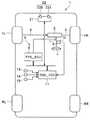
以下、図面に基づいて本発明の一実施形態を説明する。図1において、車両(自車両)1には、左右前輪FL,FRと左右後輪RL,RRとが配設されており、この左右前輪FL,FRが、ラック&ピニオン機構等のステアリング機構2にタイロッド3を介して連設されている。又、このステアリング機構2に、先端にハンドル4を固設するステアリング軸5が連設されている。運転者がハンドル4を操作すると、ステアリング機構2を介して前輪FL,FRが転舵される。 Hereinafter, an embodiment of the present invention will be described with reference to the drawings. In FIG. 1, a vehicle (own vehicle) 1 is provided with left and right front wheels FL and FR and left and right rear wheels RL and RR. The left and right front wheels FL and FR are steering
又、ステアリング軸5に電動パワーステアリング(EPS)装置6のEPSモータ7が、図示しない伝達機構を介して連設されている。EPS装置6はEPSモータ7とEPS制御ユニット(EPS_ECU)8とを有しており、このEPS_ECU8にて、EPSモータ7がステアリング軸5に付加するアシストトルクを制御する。EPS_ECU8は後述するハンドル角センサ12で検出するハンドル角、及び車速センサ13で検出する車速等に応じ、運転者がハンドル4に加える操舵トルクをアシストするアシストトルクを設定する。ステアリング軸5にアシストトルクを付加することで運転者のハンドル操作の負担が軽減される。 Further, an
又、EPS_ECU8は、例えば、CAN(Controller Area Network)通信等を用いた車内ネットワークを介して、運転者の運転支援を行う運転支援制御手段としての運転支援制御ユニット(DSS(Driving Support System)_ECU)11と接続されている。運転支援制御においては、DSS_ECU11にて設定したアシストトルクに対応する指令信号がEPS_ECU8に送信され、EPS_ECU8にてEPSモータ7に所定のアシストトルクを発生させて、自車両1が、後述する目標進行路をトレースして走行するように制御する。尚、図示しないが、車内ネットワークには、EPS_ECU8、DSS_ECU11以外に、エンジン制御ユニット、変速機制御ユニット、ブレーキ制御を含む車両操安性制御(VDC:Vehicle Dynamics Control)ユニット等、自車両1の走行状態を制御するユニット類が相互通信自在に接続されており、これら制御ユニットはマイクロコンピュータを主体に構成されている。 The EPS_ECU 8 is, for example, a driving support control unit (DSS (Driving Support System) _ECU) as a driving support control means for supporting driving of the driver via a vehicle network using CAN (Controller Area Network) communication or the like. 11 is connected. In the driving support control, a command signal corresponding to the assist torque set by the DSS_ECU 11 is transmitted to the
このDSS_ECU11は、ステアリング軸5に取り付けられてハンドル4のハンドル角を検出するハンドル角センサ12、車速を検出する車速センサ13、ハンドル4に加えられる操舵トルク、すなわち運転者による操舵トルクを検出する操舵トルクセンサ14等、自車両1の挙動を検出するセンサ類からの信号が受信される。更に、運転支援制御のON/OFFを選択すると共に、ONの場合は運転支援モード、すなわち、車線逸脱防止制御(LDP)モードと車線維持支援制御(LKSA)との何れかを選択する制御スイッチ15からの信号も受信される。 The DSS_ECU 11 is attached to the
更に、DSS_ECU11には、後述する制御開始条件を判定する際に必要とする各種パラメータを、車内ネットワークを介して各制御ユニットから受信する。尚、受信するパラメータとしては、自車両1に作用するヨーレート、4輪の車輪速等がある。又、このハンドル角センサ12で検出したハンドル角、及び車速センサ13で検出した車速は、後述する車線認識部24でも読込まれる。 Further, the DSS_ECU 11 receives various parameters necessary for determining a control start condition to be described later from each control unit via the in-vehicle network. The parameters to be received include the yaw rate acting on the
又、DSS_ECU11の出力側には、故障診断を行うパーソナルコンピュータ(図示せず)に接続される診断コネクタ16が接続されており、この診断コネクタ16を介して、パーソナルコンピュータをDSS_ECU11に接続することで、このDSS_ECU11に記憶されている、後述する不許可(NG)コードを読出すことができる。 Further, a
一方、符号21はカメラユニットであり、図2に示すように、メインカメラ22aとサブカメラ22bとからなるステレオモノクロカメラ、或いはステレオカラーカメラで構成された走行環境検出手段としての車載カメラ22と、画像処理部23、及び運転支援制御に必要な画像情報を生成する機能として、マイクロコンピュータで構成されている車線認識手段としての車線認識部24が内蔵されている。 On the other hand,
両カメラ22a,22bは、例えば車内前部のルームミラー上方であって、フロントガラスに近接する位置の車幅方向中央から左右に等間隔を開けて水平な状態で設置されている。又、この各カメラ22a,22bにCCDやCMOS等の撮像素子が設けられており、この両撮像素子によって自車両が走行している走行レーンを含む進行方向前方の走行環境の三次元画像が撮影される。尚、本実施形態では、車載カメラ22で撮影した画像データに基づいて、自車両1の走行車線や先行車を含む立体物、障害物等を認識するものである。従って、これらを認識できるものであれば、車載カメラ22に代えて、ミリ波レーダ、赤外線レーザレーダ等を採用してもよく、更には、これらとの組み合わせであっても良い。 Both
画像処理部23は、各カメラ22a,22bで撮影した一対のアナログ画像を所定輝度階調のデジタル画像に変換し、メインカメラ22aの出力信号から基準画像データを生成し、又、サブカメラ22bの出力信号から比較画像データを生成する。そして、この基準画像データ及び比較画像データとの視差に基づいて両画像中の同一対象物の三次元情報、すなわち自車両から対象物までの距離を算出する。尚、車載カメラ22は単眼カメラであっても良く、この場合、周知のモーションステレオ法等を用いて三次元情報を得ることができる。 The
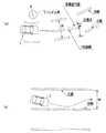
又、車線認識部24は、画像処理部23から送信される画像データに基づき左右白線を認識し、その白線の内側エッジ間の距離(車線幅)W(図5参照)を求める。尚、車線幅Wの求め方については、例えば特開2012−58984号公報等に既述されているため、詳細な説明は省略する。 Further, the
DSS_ECU11は、車線認識部24で求めた自車走行路の車線幅W、制御スイッチ15で設定した運転支援モード(LDPモード/LKSAモード)に基づき運転支援制御を実行する。 The DSS_ECU 11 executes driving support control based on the lane width W of the host vehicle traveling path obtained by the
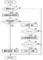
このDSS_ECU11で実行される運転支援制御は具体的には、図3に示す運転支援制御ルーチンで実行される。このルーチンは、車線認識部24から送信される1フレーム毎の画像情報に同期して起動され、先ずステップS1で、制御スイッチ15がONされているか否かを調べ、ONされている場合、ステップS2へ進み、OFFの場合、ルーチンを抜ける。 Specifically, the driving support control executed by the DSS_ECU 11 is executed by a driving support control routine shown in FIG. This routine is started in synchronization with image information for each frame transmitted from the
ステップS2では、運転支援制御を開始する前に、予め設定されている開始条件を判定する判定項目を調べる。そして、ステップS3で全ての判定項目が満足されているか否かを調べ、満足されている場合は制御開始条件成立と判定し、ステップS4へ進む。又、1つでも満足されていない場合は制御開始条件不成立と判定し、ステップS5へ分岐する。尚、このステップS2,S3での処理が、本発明の開始条件判定手段に対応している。 In step S2, before starting the driving support control, a determination item for determining a preset start condition is checked. Then, in step S3, it is checked whether all the determination items are satisfied. If satisfied, it is determined that the control start condition is satisfied, and the process proceeds to step S4. If even one is not satisfied, it is determined that the control start condition is not satisfied, and the process branches to step S5. The processes in steps S2 and S3 correspond to the start condition determining means of the present invention.
制御開始条件として設定されている判定項目の一例を以下に示す。 An example of determination items set as control start conditions is shown below.
[EPSモータ7の駆動電流が上限値以内であること]
EPSモータ7の駆動電流が上限値に達している状態は、ステアリングの据え切り等によって過大な電流が流れて過熱されていると予想され、アシストトルクを正常に制御することが困難であると判断される。そのため、NOはNG(不許可)と判定される。[The driving current of the
The state in which the driving current of the
[操舵トルクセンサ14からの出力信号が検出されていること]
手放し運転を検出する判定項目であり、所定時間内に微弱な操舵トルクが検出されていなければ、NGと判定される。[The output signal from the
This is a determination item for detecting a hand-off operation. If a weak steering torque is not detected within a predetermined time, it is determined as NG.
[ハンドル角センサ12で検出したハンドル角が所定時間内に、所定角度、且つ所定回数以上反転(切り換え)されていないこと]
急カーブの繰り返しを検出する判定項目であり、所定時間内に、所定角度、且つ所定回数以上反転(切り換え)されている場合、NGと判定される。[The steering wheel angle detected by the steering
It is a determination item for detecting the repetition of a sharp curve. If it is reversed (switched) a predetermined angle and a predetermined number of times within a predetermined time, it is determined as NG.
[VDC信号が検出されていないこと]
VDCとの制御干渉を回避するための判定項目であり、VDC信号が検出されていれば、NGと判定される。[No VDC signal detected]
This is a determination item for avoiding control interference with the VDC. If a VDC signal is detected, it is determined as NG.
[4輪のタイヤの空気圧が適正範囲に収まっていること]
1つのタイヤの空気圧が極端に低いと正常な操舵制御を行うことが困難となる。各車輪の空気圧が適正範囲に収まっているか否かの判定は、各タイヤの空気圧を直接検出することで行っても良いが、例えば、ヨーレートと4輪の車輪速とに基づいて判定することも可能である。すなわち、ヨーレートが所定範囲内の直進走行において、1つの車輪の車輪速が、他の車輪の車輪速に比し極端に遅い場合、1つのタイヤの空気圧が低いと判定する。[The tire pressure of the four wheels must be within the proper range]
If the air pressure of one tire is extremely low, it is difficult to perform normal steering control. Whether or not the air pressure of each wheel is within the appropriate range may be determined by directly detecting the air pressure of each tire. For example, the determination may be made based on the yaw rate and the wheel speed of the four wheels. Is possible. That is, when the wheel speed of one wheel is extremely slow compared with the wheel speed of the other wheel during straight traveling within a predetermined range of the yaw rate, it is determined that the air pressure of one tire is low.
[白線の内側エッジを推定する近似曲線が設定されていること]
近似曲線が設定されていない場合、車線認識部24が白線を認識していないと考えられるため、NGと判定される。ところで、濃霧、雨天、積雪等、運転者自身が白線を認識し難い状況以外に、車線認識部24が白線を認識できない状況としては、白線自体が薄くなっている、白線に影落ちがある、白線に薄く積雪されている等、運転者が白線を認識しているにも拘わらず、車線認識部24では白線の内側エッジを認識できないために、近似曲線が生成されない状況がある。[An approximate curve that estimates the inner edge of the white line must be set]
When the approximate curve is not set, it is considered that the
そして、上述したように、ステップS3で、全ての判定項目がOKと判定された場合、制御開始条件成立と判定し、ステップS4へ進み、図4に示す運転支援サブルーチンを実行して、ルーチンを抜ける。尚、この運転支援サブルーチンについては後述する。 Then, as described above, if all the determination items are determined to be OK in step S3, it is determined that the control start condition is satisfied, the process proceeds to step S4, the driving support subroutine shown in FIG. 4 is executed, and the routine is executed. Exit. This driving support subroutine will be described later.
一方、少なくとも1つの判定項目がNGと判定された場合、制御開始条件不成立と判定し、ステップS5へジャンプする。ステップS5へ進むと、ステップS5〜S9でNGコード記憶処理を実行する。このNGコード記憶処理は、運転者が制御スイッチ15をONしたにも拘わらず、運転支援制御が開始されずに故障ではないかとの疑念を抱く判定項目を絞り込んで記憶させるものである。 On the other hand, when at least one determination item is determined to be NG, it is determined that the control start condition is not satisfied, and the process jumps to step S5. In step S5, NG code storage processing is executed in steps S5 to S9. In this NG code storage process, although the driver turns on the
先ず、ステップS5で、上述したステップS2でNGと判定された判定項目を抽出し、ステップS6〜S8で抽出された判定項目の中から運転者が疑念を抱いた判定項目を絞り込む。 First, in step S5, the determination items determined as NG in step S2 described above are extracted, and the determination items for which the driver has doubts are narrowed down from the determination items extracted in steps S6 to S8.
ステップS6では車速Vと高速判定車速Voとを比較する。この高速判定車速Voは高速道路を高速走行しているか否かを判定するしきい値であり、例えば85〜95[Km/h]程度に設定されている。多くの場合、運転者が運転支援制御を必要とするのは高速道路での高速走行である。従って、現走行が高速走行であり、そのときNGとなった判定項目を絞り込む。そして、V≧Voの場合、ステップS7へ進む。又、V<Voの場合、ルーチンを抜ける。従って、V<Voの場合の判定項目は記憶されない。 In step S6, the vehicle speed V is compared with the high speed determination vehicle speed Vo. The high speed determination vehicle speed Vo is a threshold value for determining whether or not the vehicle is traveling on a highway at high speed, and is set to, for example, about 85 to 95 [Km / h]. In many cases, it is high-speed driving on a highway that the driver needs driving support control. Therefore, the current traveling is high-speed traveling, and the determination items that are judged as NG at that time are narrowed down. If V ≧ Vo, the process proceeds to step S7. If V <Vo, the routine is exited. Therefore, the determination items for V <Vo are not stored.
一方、ステップS7へ進むと、NGとなった判定項目の継続時間Tを計時し、ステップS8で、継続時間Tが設定時間Toを経過したか否か判定する。設定時間Toは運転者が故障ではないかと疑念を抱くようになる限界時間であり、例えば、20〜30[sec]程度に設定されている。この継続時間が、例えば30[sec]に設定されている場合、1秒当たりのフレーム数を30とすると、900フレーム分の移動距離で継続的に検出されている判定項目のみが絞り込まれる。尚、このステップS6〜S8での処理が、本発明の判定項目絞り込み手段に対応している。 On the other hand, if it progresses to step S7, the continuation time T of the determination item which became NG will be timed, and it will be determined whether the continuation time T passed the setting time To in step S8. The set time To is a limit time when the driver becomes suspicious that it is a failure, and is set to about 20 to 30 [sec], for example. If this duration is set to 30 [sec], for example, assuming that the number of frames per second is 30, only determination items that are continuously detected at a moving distance of 900 frames are narrowed down. The processes in steps S6 to S8 correspond to the determination item narrowing means of the present invention.
そして、T≧Toの場合、当該判定項目は運転者の限界時間を超えていると判定し、ステップS9へ進み、NGとされた判定項目(NGコード)を記憶させてルーチンを抜ける。尚、この場合、NGコードと共に記憶日時、及び記憶時の自車両1の位置(緯度及び経度)を示すGPS位置座標を記憶させるようにしても良い。 If T ≧ To, it is determined that the determination item exceeds the driver's limit time, the process proceeds to step S9, the determination item (NG code) determined as NG is stored, and the routine is exited. In this case, the storage date and time and the GPS position coordinates indicating the position (latitude and longitude) of the
このNGコードは、ディーラに備えられている故障診断用パーソナルコンピュータ(図示せず)を、診断コネクタ16を介してDSS_ECU11に接続することで読出すことができる。ディーラの作業者は納車された車両1に対し、運転者から故障ではないかとの指摘を受けた場合、故障診断用パーソナルコンピュータをDSS_ECU11に接続し、NGコードを読出すことで、運転支援制御が開始されなかった原因を解明し、運転者にそのときの状況を確認することで、運転者の抱いた疑念を解消することができる。尚、このステップS9での処理が、本発明のコード記憶手段に対応している。 The NG code can be read by connecting a fault diagnosis personal computer (not shown) provided in the dealer to the
次に、上述したステップS4で実行される運転支援制御処理について簡単に説明する。この運転支援制御処理は、図4に示す運転支援制御サブルーチンに従って実行される。このサブルーチンは、先ず、ステップS11で、車線認識部24で求めた自車走行路の車線幅Wを読込み、ステップS12で車速Vを読込む。 Next, the driving support control process executed in step S4 described above will be briefly described. This driving support control process is executed according to the driving support control subroutine shown in FIG. In this subroutine, first, in step S11, the lane width W of the own vehicle traveling path obtained by the
その後、ステップS13,S14で高速道路を走行中か否かを判定する。すなわち、ステップS13では車線幅Wが設定車線幅Ws以上か否かを判定する。この設定車線幅Wsは、走行車線が高速道路の車線幅か否かを判定するしきい値であり、例えば、2.8〜3.0[m]程度に設定されている。ステップS14では、車速Vと高速道路走行判定車速Vsとを比較する。この高速道路走行判定車速Vsは高速道路の走行を判定するしきい値であり、80〜85[Km/h]程度に設定されている。 Thereafter, in steps S13 and S14, it is determined whether or not the vehicle is traveling on a highway. That is, in step S13, it is determined whether or not the lane width W is greater than or equal to the set lane width Ws. The set lane width Ws is a threshold value for determining whether or not the travel lane is a lane width of an expressway, and is set to about 2.8 to 3.0 [m], for example. In step S14, the vehicle speed V is compared with the highway travel determination vehicle speed Vs. The highway traveling determination vehicle speed Vs is a threshold value for determining traveling on the highway, and is set to about 80 to 85 [Km / h].
そして、ステップS13でW≧Wsと判定され、且つ、ステップS15でV≧Vsと判定された場合、高速道路を走行中と判定し、ステップS15へ進む。又、ステップS13でW<Wsと判定され、或いは、ステップS15でV<Vsと判定された場合、高速道路の走行ではないと判定し、ステップS17へジャンプする。 If it is determined in step S13 that W ≧ Ws, and if it is determined in step S15 that V ≧ Vs, it is determined that the vehicle is traveling on a highway, and the process proceeds to step S15. If it is determined in step S13 that W <Ws, or if it is determined in step S15 that V <Vs, it is determined that the vehicle is not traveling on a highway, and the process jumps to step S17.
高速道路の走行と判定されてステップS15へ進むと、制御スイッチ15からの信号に基づき、運転者の選択した運転支援モードを読込む。そして、運転者がLKSAモードを選択している場合、ステップS16へ進み、LKSAモードを実行してルーチンを抜ける。一方、LDPモードが選択されている場合、ステップS17へ進む。 When it is determined that the vehicle is traveling on an expressway and the process proceeds to step S15, the driving support mode selected by the driver is read based on the signal from the
ステップS13,S14,或いはS15からステップS17へ進むと、LDPモードを実行してルーチンを抜ける。従って、本実施形態では、走行支援モードとして基本的にはLDPモードが実行され、運転者が制御スイッチ15を操作して運転支援モードとしてLKSAモードを選択した場合、高速走行においてLKSAモードが実行される。 When the process proceeds from step S13, S14, or S15 to step S17, the LDP mode is executed and the routine is exited. Therefore, in the present embodiment, the LDP mode is basically executed as the driving support mode, and when the driver operates the
LKSAモードが実行されると、図5(a)に示すように、左右車線の内側エッジから自車両1が走行すべき目標進行路(例えば、左右車線の中央)を設定し、この目標進行路の認識曲率、車速Vに基づきFF目標ハンドル角を設定する。又、ハンドル角センサ12で検出したハンドル角(実ハンドル角)と車速Vに基づきFB曲率を設定し、このFB曲率に基づいて自車両1進行方向における所定時間経過後の位置(目標点)を求め、この目標点と目標進行路とのずれ幅Δcが0となるようなFB目標ハンドル角を設定する。そして、FF目標ハンドル角にFR目標ハンドル角を加算して最終的な指示ハンドル角を設定し、この指示ハンドル角に対応するEPS付加トルクをEPS_ECU8へ送信し、EPSモータ7を駆動させて、自車両1が目標進行路に沿って走行するように操舵制御を行う。 When the LKSA mode is executed, as shown in FIG. 5A, a target travel path (for example, the center of the left and right lanes) on which the
一方、LDPモードが実行されると、図5(b)に示すように、DSS_ECU11は、走行車線を区画する白線の内側エッジを推定する近似曲線に対し、自車両1が逸脱傾向にあると判断した場合に、運転者にその旨を警告すると共に、自車両1を車線中央側へ戻す付加トルク指示値をEPS_ECU8へ送信し、EPSモータ7を駆動させて、車線逸脱を防止する。 On the other hand, when the LDP mode is executed, as shown in FIG. 5B, the
このように、本実施形態では、運転支援制御を開始するに際して判定する制御開始条件の判定項目のうち、NGとなった判定項目のコード(NGコード)を、そのまま記憶させるのではなく、主に、運転者が故障ではないかとの疑義を抱く判定項目を絞り込んで、そのNGコードを記憶させるようにしたので、ディーラの作業者は、このNGコードに基づき運転支援制御が開始されなかった原因を容易に解明することができる。 As described above, in the present embodiment, among the determination items of the control start condition determined when starting the driving support control, the determination item code (NG code) that is NG is not stored as it is, but mainly. Since the NG code is memorized by narrowing down the judgment item that the driver is suspected of being out of order, the dealer operator can explain why the driving support control was not started based on this NG code. It can be easily clarified.
又、記憶するNGコードを、車速Vと継続時間Tとに基づき、高速道路を高速で走行する際に継続的にNGとなる判定項目に絞り込んだので、短時間でより明確に原因を探求することができる。 Moreover, since the NG code to be stored is narrowed down to the determination items that are continuously NG when traveling on the highway at high speed based on the vehicle speed V and the duration T, the cause can be more clearly searched in a short time. be able to.
尚、本発明は、上述した実施形態に限るものではなく、例えば、記憶するNGコードを車速Vと継続時間T以外の他の要素で絞り込むようにしても良い。 Note that the present invention is not limited to the above-described embodiment. For example, the stored NG codes may be narrowed down by elements other than the vehicle speed V and the duration T.
1…自車両、
6…電動パワーステアリング(EPS)装置、
7…EPSモータ、
8…EPS制御ユニット、
11…運転支援制御ユニット、
13…車速センサ、
23…画像処理部、
24…車線認識部、
T…継続時間、
To…設定時間、
V…車速、
Vo…高速判定車速、
Vs…高速道路走行判定車速Vs、1 ... own vehicle,
6 ... Electric power steering (EPS) device,
7 ... EPS motor,
8 ... EPS control unit,
11 ... Driving support control unit,
13 ... Vehicle speed sensor,
23. Image processing unit,
24 ... Lane recognition part,
T ... Duration,
To ... set time,
V ... Vehicle speed,
Vo ... High speed judgment vehicle speed,
Vs ... Highway driving determination vehicle speed Vs,
Claims (3)
Translated fromJapanese前記走行環境検出手段で検出した走行環境に基づき自車両の走行車線を認識する車線認識手段と、
前記車線認識手段で認識した走行車線に基づき前記自車両の運転支援制御を行う運転支援制御手段と
を備える運転支援装置において、
前記運転支援制御手段は、運転支援制御を開始する際の開始条件を予め設定されている判定項目毎に判定する開始条件判定手段と、
前記開始条件判定手段で開始条件不成立と判定された場合、不許可と判定された判定項目の中から高速道路走行時に不許可と判定された判定項目を抽出する判定項目絞り込み手段と、
前記判定項目絞り込み手段で絞り込んだ判定項目を不許可コードとして記憶させるコード記憶手段と
を備えることを特徴とする運転支援装置。Driving environment detection means for detecting the driving environment in front of the host vehicle;
Lane recognition means for recognizing the travel lane of the host vehicle based on the travel environment detected by the travel environment detection means;
Driving assistance control means for performing driving assistance control of the host vehicle based on the traveling lane recognized by the lane recognition means;
In a driving support device comprising:
The driving support control means includes a start condition determination means that determines a start condition for starting the driving support control for each predetermined determination item;
When it is determined that the start condition is not satisfied by the start condition determining unit, adetermination item narrowing unit that extracts a determination item that is determined to be disapproved when traveling on a highwayfrom determination items that are determined to be disallowed;
The judgment itemsOPERATION support deviceyou further comprisinga judgment items narrowed down by narrowing means and code storage means for storing a disallowed encoding <br/>.
ことを特徴とする請求項1記載の運転支援装置。The judgment items narrowing means, No placement claim1 Symbol and extracts the judgment items for non-permission state from among the check items which are judged not permittedduring the highway driving is continued setting time Driving assistance device.
前記走行環境検出手段で検出した走行環境に基づき自車両の走行車線を認識する車線認識手段と、
前記車線認識手段で認識した走行車線に基づき前記自車両の運転支援制御を行う運転支援制御手段と
を備える運転支援装置において、
前記運転支援制御手段は、運転支援制御を開始する際の開始条件を予め設定されている判定項目毎に判定する開始条件判定手段と、
前記開始条件判定手段で開始条件不成立と判定された場合、不許可と判定された判定項目の中から不許可状態が設定時間継続している判定項目を抽出する判定項目絞り込み手段と、
前記判定項目絞り込み手段で絞り込んだ判定項目を不許可コードとして記憶させるコード記憶手段と
を備えることを特徴とする運転支援装置。Driving environment detection means for detecting the driving environment in front of the host vehicle;
Lane recognition means for recognizing the travel lane of the host vehicle based on the travel environment detected by the travel environment detection means;
Driving assistance control means for performing driving assistance control of the host vehicle based on the traveling lane recognized by the lane recognition means;
In a driving support device comprising:
The driving support control means includes a start condition determination means that determines a start condition for starting the driving support control for each predetermined determination item;
When it is determined that the start condition is not satisfied by the start condition determination unit, adetermination item narrowing unit that extracts adetermination item in which the non-permission state continues for a set timefrom among the determination items determined as non-permission,
The judgment itemsOPERATION support deviceyou further comprisinga judgment items narrowed down by narrowing means and code storage means for storing a disallowed encoding <br/>.
Priority Applications (4)
| Application Number | Priority Date | Filing Date | Title |
|---|---|---|---|
| JP2013271585AJP5936279B2 (en) | 2013-12-27 | 2013-12-27 | Driving assistance device |
| DE102014118719.9ADE102014118719A1 (en) | 2013-12-27 | 2014-12-16 | Driving support system |
| US14/578,104US9193354B2 (en) | 2013-12-27 | 2014-12-19 | Driving support system |
| CN201410833646.8ACN104742911B (en) | 2013-12-27 | 2014-12-26 | Drive assistance device |
Applications Claiming Priority (1)
| Application Number | Priority Date | Filing Date | Title |
|---|---|---|---|
| JP2013271585AJP5936279B2 (en) | 2013-12-27 | 2013-12-27 | Driving assistance device |
Publications (2)
| Publication Number | Publication Date |
|---|---|
| JP2015125707A JP2015125707A (en) | 2015-07-06 |
| JP5936279B2true JP5936279B2 (en) | 2016-06-22 |
Family
ID=53372182
Family Applications (1)
| Application Number | Title | Priority Date | Filing Date |
|---|---|---|---|
| JP2013271585AActiveJP5936279B2 (en) | 2013-12-27 | 2013-12-27 | Driving assistance device |
Country Status (4)
| Country | Link |
|---|---|
| US (1) | US9193354B2 (en) |
| JP (1) | JP5936279B2 (en) |
| CN (1) | CN104742911B (en) |
| DE (1) | DE102014118719A1 (en) |
Families Citing this family (5)
| Publication number | Priority date | Publication date | Assignee | Title |
|---|---|---|---|---|
| JP2016007894A (en)* | 2014-06-23 | 2016-01-18 | トヨタ自動車株式会社 | Attention-seeking device and travel control unit |
| CN105489025B (en)* | 2015-12-13 | 2017-12-29 | 安徽科力信息产业有限责任公司 | A kind of failure detector and its detection method for traffic road junction wagon detector |
| JP6690506B2 (en)* | 2016-11-17 | 2020-04-28 | トヨタ自動車株式会社 | In-lane driving support system for vehicles |
| KR102528232B1 (en)* | 2018-10-08 | 2023-05-03 | 현대자동차주식회사 | Vehicle, and control method for the same |
| KR20220111764A (en)* | 2021-02-01 | 2022-08-10 | 주식회사 에이치엘클레무브 | driver assistance System and control method for the same |
Family Cites Families (10)
| Publication number | Priority date | Publication date | Assignee | Title |
|---|---|---|---|---|
| JP3332501B2 (en) | 1993-10-06 | 2002-10-07 | マツダ株式会社 | Car travel control device |
| DE19916966C5 (en)* | 1999-04-15 | 2006-09-21 | Daimlerchrysler Ag | Electronic Zündstartschalter- and steering wheel lock device |
| JP4599257B2 (en)* | 2005-09-14 | 2010-12-15 | キヤノン株式会社 | Image forming method and process cartridge |
| JP4274186B2 (en)* | 2006-02-02 | 2009-06-03 | トヨタ自動車株式会社 | Failure diagnosis apparatus and failure information recording method |
| JP2011517632A (en)* | 2008-02-20 | 2011-06-16 | コンチネンタル・テーヴエス・アクチエンゲゼルシヤフト・ウント・コンパニー・オツフエネハンデルスゲゼルシヤフト | Method and assistance system for detecting objects in the vicinity of a vehicle |
| JP5513327B2 (en) | 2010-09-08 | 2014-06-04 | 富士重工業株式会社 | Lane estimation device |
| JP2012226689A (en)* | 2011-04-22 | 2012-11-15 | Fuji Heavy Ind Ltd | Environment recognition device and environment recognition method |
| JP2014530786A (en)* | 2011-10-21 | 2014-11-20 | フィスカー オートモーティブ インコーポレイテッド | System and method for controlling driving of a vehicle |
| CN103847530B (en)* | 2012-12-03 | 2017-04-12 | 通用电气公司 | Electric drive system and energy managing method thereof |
| US9053516B2 (en)* | 2013-07-15 | 2015-06-09 | Jeffrey Stempora | Risk assessment using portable devices |
- 2013
- 2013-12-27JPJP2013271585Apatent/JP5936279B2/enactiveActive
- 2014
- 2014-12-16DEDE102014118719.9Apatent/DE102014118719A1/enactivePending
- 2014-12-19USUS14/578,104patent/US9193354B2/enactiveActive
- 2014-12-26CNCN201410833646.8Apatent/CN104742911B/ennot_activeExpired - Fee Related
Also Published As
| Publication number | Publication date |
|---|---|
| CN104742911A (en) | 2015-07-01 |
| CN104742911B (en) | 2017-06-20 |
| DE102014118719A1 (en) | 2015-07-02 |
| US9193354B2 (en) | 2015-11-24 |
| JP2015125707A (en) | 2015-07-06 |
| US20150183426A1 (en) | 2015-07-02 |
Similar Documents
| Publication | Publication Date | Title |
|---|---|---|
| JP6196518B2 (en) | Driving assistance device | |
| US9610976B2 (en) | Lane departure prevention control system for vehicle | |
| JP7128623B2 (en) | Vehicle predictive control | |
| US20170334460A1 (en) | Travel control device | |
| CN106029473B (en) | For performing method, parking assistance system and the motor vehicles that motor vehicles enter the docking process of horizontal parking space | |
| CN108352117B (en) | Lane Keeping Control | |
| JP7477236B2 (en) | Lane Departure Prevention Control Device | |
| JP6377942B2 (en) | Driving assistance device | |
| JP5936279B2 (en) | Driving assistance device | |
| JP6137979B2 (en) | Lane departure prevention support device | |
| JP6595852B2 (en) | Vehicle driving support device | |
| CN112440995B (en) | Lane departure suppression control device for vehicle | |
| JP6970215B2 (en) | Vehicle control device, vehicle with it, and control method | |
| WO2012045323A1 (en) | Method and driver assistance system for warning a driver of a motor vehicle of the presence of an obstacle in an environment of the motor vehicle | |
| KR102452474B1 (en) | Apparatus for keeping virtual lane and method thereof | |
| US20200180613A1 (en) | Travel control apparatus and vehicle | |
| JP7135808B2 (en) | Collision avoidance support device | |
| JP7557327B2 (en) | Automatic steering control device | |
| US20150232089A1 (en) | Apparatus and program for setting assistance region | |
| JP5040851B2 (en) | Wakimi driving judgment device | |
| JP2003025937A (en) | Lane departure warning device | |
| JP4075800B2 (en) | White line detector | |
| JP2006031553A (en) | Vehicle lane travel support device | |
| JP6068185B2 (en) | Vehicle driving support device | |
| JP7698495B2 (en) | Parking Assistance Device |
Legal Events
| Date | Code | Title | Description |
|---|---|---|---|
| A131 | Notification of reasons for refusal | Free format text:JAPANESE INTERMEDIATE CODE: A131 Effective date:20150915 | |
| A521 | Request for written amendment filed | Free format text:JAPANESE INTERMEDIATE CODE: A523 Effective date:20151109 | |
| TRDD | Decision of grant or rejection written | ||
| A01 | Written decision to grant a patent or to grant a registration (utility model) | Free format text:JAPANESE INTERMEDIATE CODE: A01 Effective date:20160412 | |
| A61 | First payment of annual fees (during grant procedure) | Free format text:JAPANESE INTERMEDIATE CODE: A61 Effective date:20160509 | |
| R150 | Certificate of patent or registration of utility model | Ref document number:5936279 Country of ref document:JP Free format text:JAPANESE INTERMEDIATE CODE: R150 | |
| S533 | Written request for registration of change of name | Free format text:JAPANESE INTERMEDIATE CODE: R313533 | |
| R350 | Written notification of registration of transfer | Free format text:JAPANESE INTERMEDIATE CODE: R350 | |
| R250 | Receipt of annual fees | Free format text:JAPANESE INTERMEDIATE CODE: R250 | |
| R250 | Receipt of annual fees | Free format text:JAPANESE INTERMEDIATE CODE: R250 | |
| R250 | Receipt of annual fees | Free format text:JAPANESE INTERMEDIATE CODE: R250 | |
| R250 | Receipt of annual fees | Free format text:JAPANESE INTERMEDIATE CODE: R250 | |
| R250 | Receipt of annual fees | Free format text:JAPANESE INTERMEDIATE CODE: R250 | |
| R250 | Receipt of annual fees | Free format text:JAPANESE INTERMEDIATE CODE: R250 | |
| R250 | Receipt of annual fees | Free format text:JAPANESE INTERMEDIATE CODE: R250 |