JP5935681B2 - Air cleaner - Google Patents
Air cleanerDownload PDFInfo
- Publication number
- JP5935681B2 JP5935681B2JP2012275423AJP2012275423AJP5935681B2JP 5935681 B2JP5935681 B2JP 5935681B2JP 2012275423 AJP2012275423 AJP 2012275423AJP 2012275423 AJP2012275423 AJP 2012275423AJP 5935681 B2JP5935681 B2JP 5935681B2
- Authority
- JP
- Japan
- Prior art keywords
- case
- cap
- support plate
- air cleaner
- opening
- Prior art date
- Legal status (The legal status is an assumption and is not a legal conclusion. Google has not performed a legal analysis and makes no representation as to the accuracy of the status listed.)
- Expired - Fee Related
Links
- 230000002093peripheral effectEffects0.000claimsdescription30
- 238000007789sealingMethods0.000claimsdescription20
- 238000011144upstream manufacturingMethods0.000claimsdescription7
- 238000001914filtrationMethods0.000description9
- 238000000034methodMethods0.000description9
- 230000003014reinforcing effectEffects0.000description6
- 238000003780insertionMethods0.000description4
- 230000037431insertionEffects0.000description4
- 238000000465mouldingMethods0.000description4
- 229920001971elastomerPolymers0.000description3
- 229920003002synthetic resinPolymers0.000description3
- 239000000057synthetic resinSubstances0.000description3
- 238000002485combustion reactionMethods0.000description2
- 230000000694effectsEffects0.000description2
- 230000000452restraining effectEffects0.000description2
- 230000006835compressionEffects0.000description1
- 238000007906compressionMethods0.000description1
- 230000000593degrading effectEffects0.000description1
- 230000002542deteriorative effectEffects0.000description1
- 230000001771impaired effectEffects0.000description1
- 230000001788irregularEffects0.000description1
- 229920005749polyurethane resinPolymers0.000description1
Images


Classifications
- F—MECHANICAL ENGINEERING; LIGHTING; HEATING; WEAPONS; BLASTING
- F02—COMBUSTION ENGINES; HOT-GAS OR COMBUSTION-PRODUCT ENGINE PLANTS
- F02M—SUPPLYING COMBUSTION ENGINES IN GENERAL WITH COMBUSTIBLE MIXTURES OR CONSTITUENTS THEREOF
- F02M35/00—Combustion-air cleaners, air intakes, intake silencers, or induction systems specially adapted for, or arranged on, internal-combustion engines
- F02M35/02—Air cleaners
- F02M35/0201—Housings; Casings; Frame constructions; Lids; Manufacturing or assembling thereof
- F02M35/0204—Housings; Casings; Frame constructions; Lids; Manufacturing or assembling thereof for connecting or joining to other devices, e.g. pipes
- B—PERFORMING OPERATIONS; TRANSPORTING
- B01—PHYSICAL OR CHEMICAL PROCESSES OR APPARATUS IN GENERAL
- B01D—SEPARATION
- B01D46/00—Filters or filtering processes specially modified for separating dispersed particles from gases or vapours
- B01D46/0002—Casings; Housings; Frame constructions
- B—PERFORMING OPERATIONS; TRANSPORTING
- B01—PHYSICAL OR CHEMICAL PROCESSES OR APPARATUS IN GENERAL
- B01D—SEPARATION
- B01D46/00—Filters or filtering processes specially modified for separating dispersed particles from gases or vapours
- B01D46/0002—Casings; Housings; Frame constructions
- B01D46/0005—Mounting of filtering elements within casings, housings or frames
- B—PERFORMING OPERATIONS; TRANSPORTING
- B01—PHYSICAL OR CHEMICAL PROCESSES OR APPARATUS IN GENERAL
- B01D—SEPARATION
- B01D46/00—Filters or filtering processes specially modified for separating dispersed particles from gases or vapours
- B01D46/24—Particle separators, e.g. dust precipitators, using rigid hollow filter bodies
- B01D46/2403—Particle separators, e.g. dust precipitators, using rigid hollow filter bodies characterised by the physical shape or structure of the filtering element
- B01D46/2411—Filter cartridges
- B01D46/2414—End caps including additional functions or special forms
- B—PERFORMING OPERATIONS; TRANSPORTING
- B01—PHYSICAL OR CHEMICAL PROCESSES OR APPARATUS IN GENERAL
- B01D—SEPARATION
- B01D2271/00—Sealings for filters specially adapted for separating dispersed particles from gases or vapours
- B01D2271/02—Gaskets, sealings
- B01D2271/022—Axial sealings
- B—PERFORMING OPERATIONS; TRANSPORTING
- B01—PHYSICAL OR CHEMICAL PROCESSES OR APPARATUS IN GENERAL
- B01D—SEPARATION
- B01D2275/00—Filter media structures for filters specially adapted for separating dispersed particles from gases or vapours
- B01D2275/20—Shape of filtering material
- B01D2275/201—Conical shape
Landscapes
- Engineering & Computer Science (AREA)
- Chemical & Material Sciences (AREA)
- Chemical Kinetics & Catalysis (AREA)
- Physics & Mathematics (AREA)
- Geometry (AREA)
- Manufacturing & Machinery (AREA)
- Combustion & Propulsion (AREA)
- Mechanical Engineering (AREA)
- General Engineering & Computer Science (AREA)
- Filtering Of Dispersed Particles In Gases (AREA)
Description
Translated fromJapanese本発明は、筒状のケースとキャップとによってハウジングが構成され、ケース内に収容されたエレメントの外周部のシール部がケースとキャップとの間に挟持されるようにしたエアクリーナに関する。 The present invention relates to an air cleaner in which a housing is constituted by a cylindrical case and a cap, and a seal portion of an outer peripheral portion of an element accommodated in the case is sandwiched between the case and the cap.
従来から、エンジンに供給される空気を濾過するためのエアクリーナとして、筒状のケースとキャップとで構成されるハウジングと、ハウジングに収容される略筒状のエレメントとを備えたエアクリーナが知られている。 2. Description of the Related Art Conventionally, as an air cleaner for filtering air supplied to an engine, an air cleaner having a housing constituted by a cylindrical case and a cap and a substantially cylindrical element accommodated in the housing is known. Yes.
こうしたエアクリーナとしては、例えば特許文献1に記載されたものがある。この特許文献1に記載のエアクリーナでは、筒状をなすエレメントが、吸気口が形成された第1ケースと吐出口が形成された第2ケースとで構成されるハウジングに収容されている。エレメントは、その基端部において、第2ケースに支持されている。 As such an air cleaner, there exists a thing described in patent document 1, for example. In the air cleaner described in Patent Document 1, a cylindrical element is accommodated in a housing constituted by a first case in which an air inlet is formed and a second case in which an air outlet is formed. The element is supported by the second case at the base end.
ところで、エアクリーナには、エンジン性能の確保を目的として、例えば、エアクリーナにおける圧力損失を低下させることによってエンジン性能を向上させるために、エレメントの外周と第1ケースの内周との間の空間を広くするという要求がある。また、エンジンルーム内の狭いスペースにハウジングを搭載するために、ハウジング及びエレメントを円形以外の異形形状にするという要求もある。 By the way, the air cleaner has a wide space between the outer periphery of the element and the inner periphery of the first case in order to improve the engine performance by reducing the pressure loss in the air cleaner, for example, in order to ensure the engine performance. There is a request to do. Moreover, in order to mount the housing in a narrow space in the engine room, there is a demand for the housing and the element to have an irregular shape other than circular.
本発明は、上記実情に鑑みてなされたものであり、ケースの成形性を低下させることなく、ハウジングの形状に関する自由度を向上させることが可能なエアクリーナを提供することを目的とする。 The present invention has been made in view of the above circumstances, and an object of the present invention is to provide an air cleaner capable of improving the degree of freedom regarding the shape of the housing without reducing the moldability of the case.
上記目的を達成するため、本発明のエアクリーナは、一端にエア導入用の上流側の開口部が形成された筒状のケースと、このケースの他端における下流側の開口部に取り付けられたキャップとで構成されるハウジングと、前記ハウジングに収容され、前記ケースと前記キャップとによって挟持される環状のシール部を外周部に有する筒状のエレメントと、を備えたエアクリーナにおいて、前記ケースは、ケース本体と、前記ケース本体の下流側の開口部に取り付けられ、前記キャップとの協働により前記シール部を挟持するサポートプレートとを含み、前記ケース本体の下流側の開口部の周壁は、前記エレメントのシール部の外周を間隔をあけて囲繞する。In order to achieve the above object, an air cleaner according to the present invention includes a cylindrical case having an upstream opening for introducing air at one end and a cap attached to the downstream opening at the other end of the case. And an air cleaner that includes an annular seal portion, which is accommodated in the housing and sandwiched between the case and the cap, on an outer peripheral portion. a body attached to the opening of the downstream side of the case body,seen including a support plate for sandwiching the seal portion in cooperation with thecap, the peripheral wall of the opening of the downstream side of the case body, the The outer periphery of the seal part of the element is surrounded with a space .
この構成によれば、ケースは、ケース本体とサポートプレートとを含んでおり、ケース本体とシール部との間にサポートプレートが介在した状態でエレメントのシール部を挟持する。すなわち、ケース本体には、エレメントのシール部を挟持する挟持部を一体形成することが不要となる。そのため、ケース本体を成形する金型の構造の複雑化や成形工程の複雑化が回避される。その結果、ケースの成形性を低下させることなく、ケース本体の形状、ひいてはハウジングの形状に関する自由度が向上する。 According to this configuration, the case includes the case main body and the support plate, and sandwiches the seal portion of the element with the support plate interposed between the case main body and the seal portion. That is, it is not necessary to integrally form a clamping part that clamps the seal part of the element in the case body. For this reason, the complicated structure of the mold for molding the case body and the complicated molding process are avoided. As a result, the degree of freedom with respect to the shape of the case body, and thus the shape of the housing, is improved without degrading the formability of the case.
以上のように、この発明によれば、ハウジングを構成するケースがケース本体とサポートプレートとで構成されることから、ケースの成形性を低下させることなく、ハウジングの形状に関する自由度を向上させることができる。 As described above, according to the present invention, since the case constituting the housing is composed of the case body and the support plate, the degree of freedom regarding the shape of the housing can be improved without deteriorating the moldability of the case. Can do.
以下、図1〜図7を参照して、本発明におけるエアクリーナの一実施形態について説明する。 Hereinafter, with reference to FIGS. 1-7, one Embodiment of the air cleaner in this invention is described.
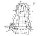
図1及び図2に示されるように、エアクリーナ10を構成するハウジング11は、断面略長円形状をなす合成樹脂製のケース12と、ケース12に対して図示されないねじ等を用いて着脱可能に取り付けられた合成樹脂製のキャップ13とで構成されている。ケース12の一端の大気に開放される開口部14の縁部には、シートラバー16が接着されている。ケース12は、エンジンルーム内において例えば図示されないフェンダーの孔の縁部に対してシートラバー16を押圧させた状態で固定される。そして、ケース12の開口部14からハウジング11に流入した吸入空気は、ハウジング11に収容されたエレメント20によって濾過された後、キャップ13の供給口18を通じてエンジンの吸気側へと供給される。 As shown in FIGS. 1 and 2, the housing 11 constituting the
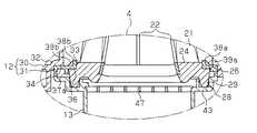
図2及び図3に示されるように、エレメント20は、濾紙からなる濾材シートを全体として筒状に成形した濾過部材21を備えている。濾過部材21は、ケース12とほぼ相似形に形成されており、エアの下流側端部から上流側端部に向けて窄まるように成形されている。濾過部材21の内側には、細枠を縦横に組み、濾過部材21の形状を保持するための合成樹脂製の補強部材22が収容されている。これら濾過部材21と補強部材22は、濾過部材21の上流側端部に形成された封止部材23と、濾過部材21の下流側端部に形成されたシールリング24とによって一体化されている。封止部材23及びシールリング24は、独立発泡のポリウレタン樹脂からなる。そして、エレメント20は、ケース12に対し、開口部14とは反対側の開口部側から挿入される。 As shown in FIGS. 2 and 3, the
図3及び図4に示されるように、シールリング24には、開口部14側の端面の外周縁部に環状の段差面26が形成され、キャップ13側の端面の外周縁部にキャップ13側へと盛り上がる環状の凸面28が形成されている。段差面26と凸面28とによって、シール部29が形成されている。 As shown in FIG. 3 and FIG. 4, the
図2〜図4に示されるように、ケース12は、筒状のケース本体30と、該ケース本体30の下流側開口部に取り付けられたリング状のサポートプレート31とで構成されている。 As shown in FIGS. 2 to 4, the
図7に示されるように、ケース本体30の周壁32には、サポートプレート31の孔35の各々に対応するようにピン状の突部34が形成されており、この突部34が、各孔35に圧入されることによって、サポートプレート31がケース本体30に対して取り付けられる。 As shown in FIG. 7, pin-
ケース本体30は、サポートプレート31の取り付けられる部位における周壁32がシールリング24の外周を間隔をおいて囲繞可能な大きさに形成されている。エレメント20は、サポートプレート31にシールリング24の段差面26が当接することによって、封止部材23が開口部14から突き出た位置でケース本体30に支持されている。 The case
図5に示されるように、サポートプレート31の中心部には、エレメント20を装着するための挿入口33が形成され、外周部に複数の前記孔35が貫通形成されている。 As shown in FIG. 5, an
また、サポートプレート31の側面には、シールリング24の段差面26が全周にわたって当接するシール面36が挿入口33を取り囲むように形成されているとともに、このシール面36とシールリング24との間でシールが確保されている。また、サポートプレート31の側面には、シール面36の外周に沿って補強用の突条部37a,37b,37cが形成されている。 Further, a
図6に示されるように、サポートプレート31には、シール面36とは反対側の面に、挿入口33の外周縁部に沿って延びる補強用の突条部38a,38bと、突条部38a,38bから外側方に延びる同じく補強用の複数のリブ39a,39bとが形成されている。 As shown in FIG. 6, the
また、図1〜図4に示されるように、ケース本体30には、開口部14から突き出たエレメント20の部位を覆う抑え部40が一体形成され、エレメント20の露出部分を保持できるようになっている。抑え部40は、開口部14の対向する壁部間に架け渡されている。この抑え部40は、振動するエレメント20と当接してそのエレメント20の過度な振動を抑える。 In addition, as shown in FIGS. 1 to 4, the
一方、図2〜図4に示されるように、キャップ13には、供給口18の入口を覆う整流板47がかしめ固定されている。整流板47は、網目状あるいは格子状をなしており、供給口18へ流入する吸入空気を整流する。また、キャップ13の上流側開口部には、シールリング24のシール部29が当接して、サポートプレート31との協働によりシールリング24をシール状態で挟持する挟持部43が形成されている。
図3に示すように、そして、キャップ13には、差込型のヒンジ部50を係合させた状態で図示されないねじ等を用いてケース12に対して取り付けられる。
次に、上述した構成のエアクリーナ10の作用について説明する。On the other hand, as shown in FIGS. 2 to 4, a rectifying
As shown in FIG. 3, the
Next, the operation of the
上述したエアクリーナ10では、エレメント20のシールリング24が、ケース12のケース本体30とは別体のサポートプレート31とキャップ13との協働によって全周にわたってシール状態で挟持されている。そして、サポートプレート31がケース本体30と別体であるため、ケース本体30には、エレメント20のシールリング24を挟持する挟持部を一体形成することが不要となる。そのため、ケース本体30においては、該ケース本体30を成形する金型の構造の複雑化や成形工程の複雑化が回避されるとともに、ケース本体30の形状に関する自由度が向上する。 In the
そして、ケース本体30は、サポートプレート31の取り付けられる部位における周壁32がエレメント20のシールリング24を間隔をおいて囲繞可能な大きさに形成されている。これにより、ケース本体30の容量が拡大されてケース本体30の内側面とエレメント20との間の間隔が広くなる。従って、濾過部材21に流入するまでの吸入空気の流速を抑えることができる。特に、濾過部材21の下流側端部においてケース本体30との間に広い通路断面積を構成する隙間が形成され、濾過部材21の下流側端部に流入する吸入空気の流速を抑えることができる。その結果、エレメント20に流入するまでに吸入空気に生じる圧力損失を抑えることができる。しかも、エレメント20がサポートプレート31上に着座しているため、キャップ13の上流側の開口部面積をサポートプレート31の開口部面積と同等にできる。従って、キャップ13も広い通路断面積を確保して、エレメント20から流出された空気の圧力損失を抑えることができる。これらのことから、エアクリーナ10を通過する際に吸入空気に生じる圧力損失を抑えることができて、エンジンの燃焼効率アップに貢献できる。 The
ちなみに、特許文献1のエアクリーナにおいては、エレメントがキャップの端面のみに着座しているため、キャップ側の通路断面積を大きくすることができず、圧力損失が大きくなる。 Incidentally, in the air cleaner of Patent Document 1, since the element is seated only on the end surface of the cap, the passage cross-sectional area on the cap side cannot be increased, and the pressure loss increases.
また、サポートプレート31は、外周部に形成された各孔35にケース本体30の突部34が圧入されることで、ケース本体30に対して取り付けられる。そのため、サポートプレート31がねじ等の固定具を用いてケース本体30に取り付けられる構成に比べて、エアクリーナ10を構成する部品が低減されるとともにケース本体30に対するサポートプレート31の取付を容易に行うことができる。また、孔35に突部34が圧入されていることで、キャップ13をケース本体30から外したときにおいて、ケース本体30からサポートプレート31が脱落することも抑えられる。その結果、エアクリーナ10の組立性が向上するとともに、エレメント20の交換時における作業性も向上する。 The
ここで、シールリング24を用いたシール方法としては、シールリング24の内周面をキャップに設けられた筒部の外周面に圧接させる内周シール、あるいは、該シールリング24の外周面をケース本体あるいはキャップに設けられた筒部の内周面に圧接させる外周シールが可能である。しかしながら、実施形態のように、外周形状が略長円形状であるシールリング24に対して上述した方法を適用した場合、長軸方向と短軸方向とでシールリング24の圧縮量が異なりやすいため、シールリング24の周方向においてシール性にばらつきが生じやすい。そのため、外周形状が長円形状をなすシールリング24を用いたシール方法としては、実施形態のように、該シールリング24を挟みこむ方法が好ましい。従って、実施形態のエアクリーナ10では、シールリング24の周方向においてシール性のばらつきが生じにくい。従って、シール性のばらつきが抑えられつつハウジング11の形状に関する自由度が向上する。 Here, as a sealing method using the
また、キャップ13には、サポートプレート31との協働により封止部材23を挟持する挟持部43が一体形成されている。そのため、ケース12と同様にキャップ13がキャップ本体とサポートプレートとを含んで構成される場合に比べて、エアクリーナ10を構成する部品が低減される。 Further, the
一方、ケース本体30には、エレメント20の振動を抑える抑え部40が一体形成されている。このため、エレメント20がケース12の下流側において片持ち支持されていても、このエレメント20の振動を抑制できるため、振動によってシールリング24によるシール性が損なわれるようなことを回避できる。
以上説明したように、上記実施形態のエアクリーナ10によれば、以下に列挙する効果を得ることができる。On the other hand, the case
As described above, according to the
(1)実施形態のエアクリーナ10では、ケース12が、ケース本体30と、ケース本体30とは別体のサポートプレート31とで構成されている。これにより、ケース本体30の成形性を低下させることなくハウジング11の形状に関する自由度が向上する。 (1) In the
(2)エレメント20のシールリング24は、その全周にわたってサポートプレート31と、キャップ13の挟持部43とで挟持される。そのため、内周シールや外周シールと比較して、ケース本体30やキャップ13の形状に関わらず適切なシール効果を得ることができる。よって、ケース本体30及びキャップ13の形状に関する自由度がさらに向上する。 (2) The
(3)ケース本体30の周壁32がシールリング24を間隔をおいて囲繞可能な大きさに形成されている。そのため、ケース本体30の通路断面積を広くして、エレメント20に流入するまでに吸入空気に生じる圧力損失、ひいてはエアクリーナ10を通過する際に吸入空気に生じる圧力損失が抑えられる。また、エレメント20がサポートプレート31に支持されているため、キャップ13に対する形状の制約が少なく、キャップ13においても、広い通路断面積を確保して圧力損失を抑えることができる。従って、エンジンの燃焼効率を向上できる。 (3) The
(4)ケース本体30の突部34が孔35に圧入されることでサポートプレート31がケース本体30に取り付けられる。そのため、エアクリーナ10を構成する部品数の増加を抑えることができる。 (4) The
(5)外周形状が長円形状をなすシールリング24は、サポートプレート31とキャップ13の挟持部43とによって挟持されている。その結果、シール性のばらつきが抑えられたうえでハウジング11の形状に関する自由度が向上する。
(6)シールリング24を挟持する挟持部43がキャップ13に一体形成されていることから、エアクリーナ10の部品数の増加を抑えることができる。
なお、上記実施形態は、以下のように適宜変更して実施することもできる。(5) The
(6) Since the clamping
In addition, the said embodiment can also be suitably changed and implemented as follows.
・キャップ13は、キャップ本体と該キャップ本体に取り付けられるサポートプレートとによって構成されてもよい。すなわち、エレメント20のシールリング24は、ケース本体30に取り付けられたサポートプレート31と、キャップ本体に取り付けられた別のサポートプレートとの協働によって挟持されてもよい。 -The
・ケース本体30及びキャップ13とエレメント20のシールリング24とは、その外周形状が略長円形状に限られるものではない。すなわち、例えば円形状であってもよいし四角形状であってもよい。 The outer peripheral shape of the
・ケース本体30に対するサポートプレート31の取付方法は、サポートプレート31の突部がケース本体30の孔に圧入される方法であってもよいし、例えばねじ等の固定具を用いた方法であってもよい。また例えば、サポートプレート31は、各孔35に挿入された突部34がかしめられることでケース本体30に取り付けられてもよい。 The method of attaching the
・ケース本体30には、抑え部40が形成されていなくてもよい。すなわち、エレメント20は、サポートプレート31とキャップ13との挟持によってシールリング24のみが支持されていてもよい。
・シールリング24のシール部29には、段差面26が形成されていなくてもよい。
・サポートプレート31には、シール面36の外周縁部に沿う突条部が該シール面36の全周にわたって形成されていてもよい。-The
The
The
10…エアクリーナ、11…ハウジング、12…ケース、13…キャップ、14…開口部、16…シートラバー、18…供給口、20…エレメント、21…濾過部材、22…補強部材、23…封止部材、24…シールリング、26…段差面、28…凸面、29…シール部、30…ケース本体、31…サポートプレート、32…周壁、33…挿入口、34…突部、35…孔、36…シール面、37a,37b,37c,38a,38b…突条部、39a,39b…リブ、40…抑え部、43…挟持部、47…整流板、50…ヒンジ部。 DESCRIPTION OF
Claims (4)
Translated fromJapanese前記ハウジングに収容され、前記ケースと前記キャップとによって挟持される環状のシール部を外周部に有する筒状のエレメントと、を備えたエアクリーナにおいて、
前記ケースは、
ケース本体と、前記ケース本体の下流側の開口部に取り付けられ、前記キャップとの協働により前記シール部を挟持するサポートプレートとを含み、
前記ケース本体の下流側の開口部の周壁は、前記エレメントのシール部の外周を間隔をあけて囲繞する
ことを特徴とするエアクリーナ。A housing composed of a cylindrical case in which an upstream opening for air introduction is formed at one end and a cap attached to a downstream opening in the other end of the case;
In an air cleaner comprising: a cylindrical element that is accommodated in the housing and has an annular seal portion at an outer peripheral portion sandwiched between the case and the cap;
The case is
A case body, attached to the opening of the downstream side of the case body,seen including a support plate for sandwiching the seal portion in cooperation with saidcap,
An air cleaner characterizedin thatthe peripheral wall of the opening on the downstream side of the case main body surrounds the outer periphery of the seal portion of the element with a space therebetween .
前記ハウジングに収容され、前記ケースと前記キャップとによって挟持される環状のシール部を外周部に有する筒状のエレメントと、を備えたエアクリーナにおいて、
前記ケースは、
ケース本体と、前記ケース本体の下流側の開口部に取り付けられ、前記キャップとの協働により前記シール部を挟持するサポートプレートとを含み、
前記ケース本体及び前記サポートプレートの一方に突部が形成され、
前記ケース本体及び前記サポートプレートの他方に前記突部が圧入される孔が形成されている
ことを特徴とするエアクリーナ。A housing composed of a cylindrical case in which an upstream opening for air introduction is formed at one end and a cap attached to a downstream opening in the other end of the case;
In an air cleaner comprising: a cylindrical element that is accommodated in the housing and has an annular seal portion at an outer peripheral portion sandwiched between the case and the cap;
The case is
A case main body, and a support plate attached to the opening on the downstream side of the case main body and sandwiching the seal portion in cooperation with the cap;
A protrusion is formed on one of the case body and the support plate,
A hole into which the protrusion is press-fitted is formed in the other of the case body and the support plate.
An air cleanercharacterized by that .
請求項1または2に記載のエアクリーナ。An air cleaner according to claim1 or 2 outer peripheral shape of the sealing portion forms a oval.
前記サポートプレートとの協働により前記シール部を挟持する挟持部が一体形成されている
請求項1〜3のいずれか一項に記載のエアクリーナ。The cap includes
The air cleaner as described in any one of Claims1-3 . The clamping part which clamps the said seal part by cooperation with the said support plate is integrally formed.
Priority Applications (2)
| Application Number | Priority Date | Filing Date | Title |
|---|---|---|---|
| JP2012275423AJP5935681B2 (en) | 2012-12-18 | 2012-12-18 | Air cleaner |
| US14/096,453US9440173B2 (en) | 2012-12-18 | 2013-12-04 | Air cleaner |
Applications Claiming Priority (1)
| Application Number | Priority Date | Filing Date | Title |
|---|---|---|---|
| JP2012275423AJP5935681B2 (en) | 2012-12-18 | 2012-12-18 | Air cleaner |
Publications (2)
| Publication Number | Publication Date |
|---|---|
| JP2014118903A JP2014118903A (en) | 2014-06-30 |
| JP5935681B2true JP5935681B2 (en) | 2016-06-15 |
Family
ID=50929301
Family Applications (1)
| Application Number | Title | Priority Date | Filing Date |
|---|---|---|---|
| JP2012275423AExpired - Fee RelatedJP5935681B2 (en) | 2012-12-18 | 2012-12-18 | Air cleaner |
Country Status (2)
| Country | Link |
|---|---|
| US (1) | US9440173B2 (en) |
| JP (1) | JP5935681B2 (en) |
Families Citing this family (7)
| Publication number | Priority date | Publication date | Assignee | Title |
|---|---|---|---|---|
| DE102012005530A1 (en)* | 2012-03-21 | 2013-09-26 | Mann+Hummel Gmbh | Method for producing a filter element provided with a sealing part |
| BR112015001748B1 (en)* | 2012-07-25 | 2022-03-15 | Baldwin Filters, Inc | filter set |
| US10058809B2 (en)* | 2012-09-27 | 2018-08-28 | Environmental Management Confederation, Inc. | Air cleaner frame |
| US10486096B2 (en) | 2014-09-09 | 2019-11-26 | Cummins Filtration Ip, Inc. | Axial flow air filter element |
| DE102016006607A1 (en) | 2016-06-02 | 2017-12-07 | Mann+Hummel Gmbh | Filter element of a filter device, filter housing and filter device |
| DE112019002182B4 (en)* | 2018-04-27 | 2024-01-11 | Mann+Hummel Gmbh | ROUND FILTER ELEMENT, ESPECIALLY FOR GAS FILTRATION AND FILTER DEVICE |
| DE102018004041A1 (en)* | 2018-05-18 | 2019-11-21 | Mann+Hummel Gmbh | Air filter element with circumferentially protruding clean air seal, filter housing and air filter |
Family Cites Families (35)
| Publication number | Priority date | Publication date | Assignee | Title |
|---|---|---|---|---|
| US4135899A (en)* | 1977-05-25 | 1979-01-23 | Donaldson Company, Inc. | Safety filter for air cleaner |
| DE8019041U1 (en)* | 1980-07-16 | 1981-04-16 | Filterwerk Mann & Hummel Gmbh, 7140 Ludwigsburg | INTAKE AIR FILTER OF INTERNAL COMBUSTION ENGINES |
| EP0059562B1 (en)* | 1981-02-23 | 1986-05-28 | Nippondenso Co., Ltd. | Fluid cleaner systems |
| JPS5874123A (en)* | 1981-10-28 | 1983-05-04 | Nippon Denso Co Ltd | Assembly of filter element |
| US4609465A (en)* | 1984-05-21 | 1986-09-02 | Pall Corporation | Filter cartridge with a connector seal |
| US4764191A (en)* | 1987-10-05 | 1988-08-16 | Aldo Morelli | Air filter |
| US5679122A (en)* | 1993-08-14 | 1997-10-21 | Minnesota Mining & Manufacturing Company | Filter for the filtration of a fluid flow |
| JP3299622B2 (en)* | 1994-03-11 | 2002-07-08 | 豊田紡織株式会社 | Air cleaner device |
| US5484529A (en)* | 1994-06-29 | 1996-01-16 | Ametek, Inc., Plymouth Products Division | Bag filter system with multifilter adaptability |
| US5605554A (en)* | 1995-08-30 | 1997-02-25 | Siemens Electric Limited | Multi-piece air filter housing and closure arrangement |
| US5916435A (en)* | 1997-01-27 | 1999-06-29 | Porous Media Corporation | Conical coreless filter assembly and element |
| US6329625B1 (en)* | 1998-10-05 | 2001-12-11 | Usf Filtration & Separations Group, Inc. | Method of making a seal |
| DE19856520A1 (en)* | 1998-12-08 | 2000-06-15 | Mann & Hummel Filter | Housing, in particular filter housing with filter insert |
| US6572667B1 (en)* | 1999-11-09 | 2003-06-03 | Filterwerk Mann & Hummel Gmbh | Filter system |
| US6416561B1 (en)* | 2000-10-20 | 2002-07-09 | Nelson Industries, Inc. | Open flow filter with safety element |
| US6667364B2 (en)* | 2000-12-29 | 2003-12-23 | Advanced Elastomer Systems Lp | Processable polyethylene/EPDM thermoplastic vulcanizates |
| JP3995891B2 (en)* | 2001-03-08 | 2007-10-24 | トヨタ紡織株式会社 | Air cleaner |
| US6966940B2 (en)* | 2002-04-04 | 2005-11-22 | Donaldson Company, Inc. | Air filter cartridge |
| US6890366B2 (en)* | 2003-04-17 | 2005-05-10 | Visteon Global Technologies, Inc. | Sealed engine air filter system |
| JP4424084B2 (en)* | 2004-06-21 | 2010-03-03 | トヨタ紡織株式会社 | Fuel vapor adsorption filter and air cleaner provided with the same |
| US7247183B2 (en)* | 2004-09-29 | 2007-07-24 | Fleetguard, Inc. | Panel filter with gasket seal |
| US20060091061A1 (en)* | 2004-11-02 | 2006-05-04 | Baldwin Filters, Inc. | Filter assembly with sealing system |
| US7931725B2 (en)* | 2004-11-02 | 2011-04-26 | Baldwin Filters, Inc. | Fluted filter apparatus |
| JP4727536B2 (en)* | 2005-09-21 | 2011-07-20 | 株式会社Roki | Air cleaner |
| EP1965888B1 (en)* | 2005-11-09 | 2011-08-03 | Donaldson Company, Inc. | Seal arrangement for filter cartridge |
| DE202006001440U1 (en)* | 2006-01-31 | 2007-06-14 | Mann+Hummel Gmbh | Filter element and filter system, in particular for the intake air of an internal combustion engine |
| DE102006028161A1 (en)* | 2006-06-16 | 2007-12-27 | Mann + Hummel Gmbh | Compact filter element with knock-out protection |
| US20080000820A1 (en)* | 2006-06-30 | 2008-01-03 | Mitchell Alan J | Water Filter Cartridge and Valve with Autobypass Feature |
| JP4744391B2 (en)* | 2006-08-09 | 2011-08-10 | 株式会社Roki | Air cleaner |
| DE102009009066A1 (en)* | 2009-02-16 | 2010-08-26 | Mann + Hummel Gmbh | Filter device for the filtration of gaseous fluids |
| CN102119269B (en)* | 2008-06-11 | 2014-06-25 | 曼·胡默尔有限公司 | Filter device for filtering gaseous fluids |
| US8048187B2 (en)* | 2008-06-30 | 2011-11-01 | Baldwin Filters, Inc. | Filter frame attachment and fluted filter having same |
| US8152887B2 (en)* | 2008-12-15 | 2012-04-10 | Mann + Hummel Gmbh | Air/oil separator |
| US8506668B2 (en)* | 2009-03-30 | 2013-08-13 | Baldwin Filters, Inc. | Fluted filter with axial seal |
| JP2012112311A (en) | 2010-11-25 | 2012-06-14 | Toyota Boshoku Corp | Air filter and air cleaner |
- 2012
- 2012-12-18JPJP2012275423Apatent/JP5935681B2/ennot_activeExpired - Fee Related
- 2013
- 2013-12-04USUS14/096,453patent/US9440173B2/ennot_activeExpired - Fee Related
Also Published As
| Publication number | Publication date |
|---|---|
| JP2014118903A (en) | 2014-06-30 |
| US9440173B2 (en) | 2016-09-13 |
| US20140165518A1 (en) | 2014-06-19 |
Similar Documents
| Publication | Publication Date | Title |
|---|---|---|
| JP5935681B2 (en) | Air cleaner | |
| CN106973567B (en) | Filters and Cartridges | |
| JP4744391B2 (en) | Air cleaner | |
| KR102123125B1 (en) | Flat filter element of a filter, filter and support device of a filter | |
| JP2008513193A (en) | Filter element | |
| US20140209528A1 (en) | Filter with dual pleat pack | |
| JP5202729B2 (en) | Liquid-filled vibration isolator | |
| JP2017180779A (en) | Liquid-seal vibration isolator | |
| JP4958733B2 (en) | Oil strainer | |
| US10767606B2 (en) | Tubular air cleaner for internal combustion engine and tubular filter element | |
| CN105246571B (en) | Filter with double pleated pack | |
| JP2018071424A (en) | Cylindrical air cleaner | |
| KR200471437Y1 (en) | Air filter for vehicle | |
| JP2016121584A (en) | Air cleaner and filter element | |
| JP4506634B2 (en) | Filter and cleaner | |
| CN219101478U (en) | Sealing assembly, air filter and motorcycle | |
| JP2021085372A (en) | Air cleaner | |
| CN108778447B (en) | Interlocking Stable Filter Assembly | |
| JP6202956B2 (en) | Intake duct for vehicle | |
| JP2019519363A (en) | Filter devices, in particular gas filters | |
| CN115962073B (en) | Sealing components, air filters and motorcycles | |
| JP2018105217A (en) | Air cleaner of internal combustion engine | |
| JP5778716B2 (en) | Air cleaner | |
| US12158127B2 (en) | Air cleaner | |
| JP5616825B2 (en) | Liquid-filled vibration isolator |
Legal Events
| Date | Code | Title | Description |
|---|---|---|---|
| A621 | Written request for application examination | Free format text:JAPANESE INTERMEDIATE CODE: A621 Effective date:20150423 | |
| A977 | Report on retrieval | Free format text:JAPANESE INTERMEDIATE CODE: A971007 Effective date:20160218 | |
| A131 | Notification of reasons for refusal | Free format text:JAPANESE INTERMEDIATE CODE: A131 Effective date:20160223 | |
| A521 | Request for written amendment filed | Free format text:JAPANESE INTERMEDIATE CODE: A523 Effective date:20160318 | |
| TRDD | Decision of grant or rejection written | ||
| A01 | Written decision to grant a patent or to grant a registration (utility model) | Free format text:JAPANESE INTERMEDIATE CODE: A01 Effective date:20160412 | |
| A61 | First payment of annual fees (during grant procedure) | Free format text:JAPANESE INTERMEDIATE CODE: A61 Effective date:20160425 | |
| R151 | Written notification of patent or utility model registration | Ref document number:5935681 Country of ref document:JP Free format text:JAPANESE INTERMEDIATE CODE: R151 | |
| R250 | Receipt of annual fees | Free format text:JAPANESE INTERMEDIATE CODE: R250 | |
| R250 | Receipt of annual fees | Free format text:JAPANESE INTERMEDIATE CODE: R250 | |
| LAPS | Cancellation because of no payment of annual fees |