JP5934537B2 - Electronic device and control method of electronic device - Google Patents
Electronic device and control method of electronic deviceDownload PDFInfo
- Publication number
- JP5934537B2 JP5934537B2JP2012072498AJP2012072498AJP5934537B2JP 5934537 B2JP5934537 B2JP 5934537B2JP 2012072498 AJP2012072498 AJP 2012072498AJP 2012072498 AJP2012072498 AJP 2012072498AJP 5934537 B2JP5934537 B2JP 5934537B2
- Authority
- JP
- Japan
- Prior art keywords
- detection unit
- contact
- input
- contact detection
- unit
- Prior art date
- Legal status (The legal status is an assumption and is not a legal conclusion. Google has not performed a legal analysis and makes no representation as to the accuracy of the status listed.)
- Active
Links
Images


Classifications
- G—PHYSICS
- G06—COMPUTING OR CALCULATING; COUNTING
- G06F—ELECTRIC DIGITAL DATA PROCESSING
- G06F3/00—Input arrangements for transferring data to be processed into a form capable of being handled by the computer; Output arrangements for transferring data from processing unit to output unit, e.g. interface arrangements
- G06F3/01—Input arrangements or combined input and output arrangements for interaction between user and computer
- G06F3/03—Arrangements for converting the position or the displacement of a member into a coded form
- G06F3/041—Digitisers, e.g. for touch screens or touch pads, characterised by the transducing means
- G06F3/0416—Control or interface arrangements specially adapted for digitisers
- G—PHYSICS
- G06—COMPUTING OR CALCULATING; COUNTING
- G06F—ELECTRIC DIGITAL DATA PROCESSING
- G06F3/00—Input arrangements for transferring data to be processed into a form capable of being handled by the computer; Output arrangements for transferring data from processing unit to output unit, e.g. interface arrangements
- G06F3/01—Input arrangements or combined input and output arrangements for interaction between user and computer
- G06F3/016—Input arrangements with force or tactile feedback as computer generated output to the user
- G—PHYSICS
- G06—COMPUTING OR CALCULATING; COUNTING
- G06F—ELECTRIC DIGITAL DATA PROCESSING
- G06F3/00—Input arrangements for transferring data to be processed into a form capable of being handled by the computer; Output arrangements for transferring data from processing unit to output unit, e.g. interface arrangements
- G06F3/01—Input arrangements or combined input and output arrangements for interaction between user and computer
- G06F3/048—Interaction techniques based on graphical user interfaces [GUI]
- G06F3/0487—Interaction techniques based on graphical user interfaces [GUI] using specific features provided by the input device, e.g. functions controlled by the rotation of a mouse with dual sensing arrangements, or of the nature of the input device, e.g. tap gestures based on pressure sensed by a digitiser
- G06F3/0488—Interaction techniques based on graphical user interfaces [GUI] using specific features provided by the input device, e.g. functions controlled by the rotation of a mouse with dual sensing arrangements, or of the nature of the input device, e.g. tap gestures based on pressure sensed by a digitiser using a touch-screen or digitiser, e.g. input of commands through traced gestures
- H—ELECTRICITY
- H04—ELECTRIC COMMUNICATION TECHNIQUE
- H04M—TELEPHONIC COMMUNICATION
- H04M1/00—Substation equipment, e.g. for use by subscribers
- H04M1/247—Telephone sets including user guidance or feature selection means facilitating their use
- H04M1/2477—Telephone sets including user guidance or feature selection means facilitating their use for selecting a function from a menu display
- H—ELECTRICITY
- H04—ELECTRIC COMMUNICATION TECHNIQUE
- H04M—TELEPHONIC COMMUNICATION
- H04M1/00—Substation equipment, e.g. for use by subscribers
- H04M1/72—Mobile telephones; Cordless telephones, i.e. devices for establishing wireless links to base stations without route selection
- H04M1/724—User interfaces specially adapted for cordless or mobile telephones
- G—PHYSICS
- G06—COMPUTING OR CALCULATING; COUNTING
- G06F—ELECTRIC DIGITAL DATA PROCESSING
- G06F2203/00—Indexing scheme relating to G06F3/00 - G06F3/048
- G06F2203/041—Indexing scheme relating to G06F3/041 - G06F3/045
- G06F2203/04105—Pressure sensors for measuring the pressure or force exerted on the touch surface without providing the touch position
- G—PHYSICS
- G06—COMPUTING OR CALCULATING; COUNTING
- G06F—ELECTRIC DIGITAL DATA PROCESSING
- G06F2203/00—Indexing scheme relating to G06F3/00 - G06F3/048
- G06F2203/041—Indexing scheme relating to G06F3/041 - G06F3/045
- G06F2203/04106—Multi-sensing digitiser, i.e. digitiser using at least two different sensing technologies simultaneously or alternatively, e.g. for detecting pen and finger, for saving power or for improving position detection
- H—ELECTRICITY
- H04—ELECTRIC COMMUNICATION TECHNIQUE
- H04M—TELEPHONIC COMMUNICATION
- H04M1/00—Substation equipment, e.g. for use by subscribers
- H04M1/72—Mobile telephones; Cordless telephones, i.e. devices for establishing wireless links to base stations without route selection
- H04M1/724—User interfaces specially adapted for cordless or mobile telephones
- H04M1/72403—User interfaces specially adapted for cordless or mobile telephones with means for local support of applications that increase the functionality
- H04M1/72418—User interfaces specially adapted for cordless or mobile telephones with means for local support of applications that increase the functionality for supporting emergency services
- H04M1/72424—User interfaces specially adapted for cordless or mobile telephones with means for local support of applications that increase the functionality for supporting emergency services with manual activation of emergency-service functions
Landscapes
- Engineering & Computer Science (AREA)
- General Engineering & Computer Science (AREA)
- Theoretical Computer Science (AREA)
- Human Computer Interaction (AREA)
- Physics & Mathematics (AREA)
- General Physics & Mathematics (AREA)
- Signal Processing (AREA)
- Computer Networks & Wireless Communication (AREA)
- Computer Vision & Pattern Recognition (AREA)
- Telephone Function (AREA)
- User Interface Of Digital Computer (AREA)
- Input From Keyboards Or The Like (AREA)
Description
Translated fromJapanese本発明は、電子機器および電子機器の制御方法に関するものである。より詳細には、タッチセンサなどの接触検出部に対する入力に基づいて、アプリケーションソフトウェアを実行させるなど所定の処理を行う電子機器およびその制御方法に関するものである。The present invention relates to an electronic deviceand a method forcontrolling the electronic device . More specifically, the presentinvention relates to an electronic device that performs a predetermined process such as executing application software based on an input to a contact detection unit such as a touch sensor and acontrol method thereof .
近年、使用者からの多様な入力に応じた多様な機能を実行する電子機器例えば、携帯電話端末およびパーソナルコンピュータが知られている。このような電子機器への入力の中には、特定の入力の間違えた実行が通常の入力に比べて好ましくないことがある。 2. Description of the Related Art In recent years, electronic devices that perform various functions according to various inputs from users, such as mobile phone terminals and personal computers, are known. Among such inputs to an electronic device, a wrong execution of a specific input may be less preferable than a normal input.
例えば、携帯端末では110番などの緊急通報が可能である(特許文献1参照)。このような緊急通報は広範に影響を及ぼし得るので、緊急通報の誤操作は、通常の連絡先への発呼の誤操作以上に、十分に抑制することが望まれる。 For example, an emergency call such as 110 can be made on a mobile terminal (see Patent Document 1). Since such an emergency call can affect a wide range, it is desired that an erroneous operation of an emergency call is sufficiently suppressed more than an erroneous operation of a call to a normal contact.
また、アドレス帳等のデータ削除において、操作者が操作に慣れてくると削除すべきデータかの確認を怠ることが多い。このような場合に連続したキーの押下により誤って必要なデータを削除してしまうことがある。このように後に回復不能な誤操作も通常の操作に比べて十分に抑制することが望まれる。 In addition, when deleting data such as an address book, the operator often neglects to confirm whether data should be deleted as he / she gets used to the operation. In such a case, necessary data may be mistakenly deleted by successive key presses. Thus, it is desirable to sufficiently suppress an erroneous operation that cannot be recovered later as compared with a normal operation.
したがって、かかる事情に鑑みてなされた本発明の目的は、特定の入力に対して、通常の入力以上に誤操作を抑制し得る電子機器および電子機器の制御方法を提供することにある。Therefore, the objective of this invention made | formed in view of this situation is providingthe control method ofan electronic deviceand an electronic device which can suppress a misoperation more than a normal input with respect to a specific input.
上述した諸課題を解決すべく、本発明による第1の電子機器は、
接触を検出する接触検出部と、
前記接触検出部に対する押圧を検出する押圧検出部と、
オブジェクトを表示する表示部と、
前記接触検出部を振動させる振動部と、
入力を受け付ける制御部とを備え、
前記制御部は、入力済みのデータに応じて、入力を受け付けるための前記押圧に関する閾値を前記オブジェクトに対して設定し、
入力の受付が前記押圧に基づいて判別されるオブジェクトに対して前記接触検出部により接触が検知された場合に、
前記オブジェクトに対して設定された閾値が所定の閾値でなければ前記振動部により前記接触検出部を振動させ、
前記オブジェクトに対して設定された閾値が所定の閾値であれば前記振動部により前記接触検出部を振動させない
ことを特徴とするものである。In order to solve the above-described problems, a first electronic device according to the present invention includes:
A contact detector for detecting contact;
A pressure detection unit that detects pressure on the contact detection unit;
A display for displaying objects;
A vibrating section that vibrates the contact detection section;
A control unit for receiving input,
The control unit sets, for theobject, a threshold value related to the pressing for receiving an input according to the input data,
When contact is detected by the contact detection unit with respect to an object whose input is determined based on the pressure,
Ifthe threshold set for the object is not a predetermined threshold, the vibration detection unit vibrates the contact detection unit,
If the thresholdset for the object is a predetermined threshold, the contact detecting unit is not vibrated by the vibrating unit.
また、本発明による第2の電子機器は、
接触を検出する接触検出部と、
前記接触検出部に対する押圧を検出する押圧検出部と、
オブジェクトを表示する表示部と、
前記接触検出部を振動させる振動部と、
入力を受け付ける制御部とを備え、
前記制御部は、入力済みのデータに応じて、前記オブジェクトに対して設定された、入力を受け付けるための前記押圧に関する閾値を変化させ、
入力の受付が前記押圧に基づいて判別されるオブジェクトに対して前記接触検出部により接触が検知された場合に、
前記オブジェクトに対して設定された閾値が所定の閾値でなければ前記振動部により前記接触検出部を振動させ、
前記オブジェクトに対して設定された閾値が所定の閾値であれば前記振動部により前記接触検出部を振動させない
ことが好ましい。A second electronic device according to the present invention is
A contact detector for detecting contact;
A pressure detection unit that detects pressure on the contact detection unit;
A display for displaying objects;
A vibrating section that vibrates the contact detection section;
A control unit for receiving input,
The control unit changes a threshold related to the pressing for acceptingan input,which is set for the object , in accordance with input data,
When contact is detected by the contact detection unit with respect to an object whose input is determined based on the pressure,
Ifthe threshold set for the object is not a predetermined threshold, the vibration detection unit vibrates the contact detection unit,
If the thresholdset for the object is a predetermined threshold, the contact detection unit is preferably not vibrated by the vibration unit.
また、
制御部は、閾値に基づいてオブジェクトへの入力を受け付け、所定の機能の実行を確定するオブジェクトへの入力を受け付ける閾値を該オブジェクトに対する所定の値に設定する
ことが好ましい。Also,
A control unit receives an input of the object based on the threshold value, it is preferable to set a threshold for accepting an input to the object to determine the execution of the predetermined function to a predetermined value for the object.
また、
制御部は、表示部に表示中の少なくとも一部のオブジェクトへの入力を受け付けるための閾値を該オブジェクトに応じた値に設定する
ことが好ましい。Also,
A control unit is preferably set to at least a value corresponding to the object a threshold for accepting an input of a part to the object being displayed on the display unit.
また、本発明を方法として実現させた第1の電子機器の制御方法は、
接触検出部が接触を検出する接触検出ステップと、
押圧検出部が前記接触検出部に対する押圧を検出する押圧検出ステップと、
表示部がオブジェクトを表示する表示ステップと、
入力を受け付けて振動部による前記接触検出部の振動を制御する振動制御ステップとを含み、
前記振動制御ステップは、入力済みのデータに応じて、入力を受け付けるための前記押圧に関する閾値を前記オブジェクトに対して設定し、
入力の受付が前記押圧に基づいて判別されるオブジェクトに対して前記接触検出ステップで接触が検知された場合に、
前記オブジェクトに対して設定された閾値が所定の閾値でなければ前記振動部により前記接触検出部を振動させ、
前記オブジェクトに対して設定された閾値が所定の閾値であれば前記振動部により前記接触検出部を振動させない
ことを特徴とするものである。In addition, a control method of the first electronic device that realizes the present invention as a method,
A contact detection step in which the contact detection unit detects contact; and
A pressure detection step in which the pressure detection unit detects a pressure on the contact detection unit; and
A display step in which the display unit displays the object;
A vibration control step for receiving an input and controlling the vibration of the contact detection unit by the vibration unit,
The vibration control step sets, for theobject, a threshold value related to the pressing for accepting an input according to the input data,
When contact is detected in the contact detection step for an object whose input is determined based on the pressure,
Ifthe threshold set for the object is not a predetermined threshold, the vibration detection unit vibrates the contact detection unit,
If the thresholdset for the object is a predetermined threshold, the contact detecting unit is not vibrated by the vibrating unit.
また、本発明による第2の電子機器の制御方法は、
接触検出部が接触を検出する接触検出ステップと、
押圧検出部が前記接触検出部に対する押圧を検出する押圧検出ステップと、
表示部がオブジェクトを表示する表示ステップと、
入力を受け付けて振動部による前記接触検出部の振動を制御する振動制御ステップとを含み、
前記振動制御ステップは、入力済みのデータに応じて、前記オブジェクトに対して設定された、入力を受け付けるための前記押圧に関する閾値を変化させ、
入力の受付が前記押圧に基づいて判別されるオブジェクトに対して前記接触検出ステップで接触が検知された場合に、
前記オブジェクトに対して設定された閾値が所定の閾値でなければ前記振動部により前記接触検出部を振動させ、
前記オブジェクトに対して設定された閾値が所定の閾値であれば前記振動部により前記接触検出部を振動させない
ことを特徴とするものである。In addition, a second electronic device control method according to the present invention includes:
A contact detection step in which the contact detection unit detects contact; and
A pressure detection step in which the pressure detection unit detects a pressure on the contact detection unit; and
A display step in which the display unit displays the object;
A vibration control step for receiving an input and controlling the vibration of the contact detection unit by the vibration unit,
The vibration control step changes a threshold value related to the pressing for acceptingan input,which is set for the object , according to input data,
When contact is detected in the contact detection step for an object whose input is determined based on the pressure,
Ifthe threshold set for the object is not a predetermined threshold, the vibration detection unit vibrates the contact detection unit,
If the thresholdset for the object is a predetermined threshold, the contact detecting unit is not vibrated by the vibrating unit.
上記のように構成された本発明に係る電子機器によれば、特定の入力に対して通常の入力以上に誤操作を抑制可能である。 According to the electronic device according to the present invention configured as described above, it is possible to suppress erroneous operations with respect to a specific input more than a normal input.
以下、本発明の実施形態について、図面を参照して説明する。 Hereinafter, embodiments of the present invention will be described with reference to the drawings.
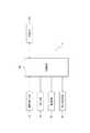
図1は、本実施形態に係る電子機器の概略構成を示すブロック図である。 FIG. 1 is a block diagram illustrating a schematic configuration of an electronic apparatus according to the present embodiment.
本実施形態に係る電子機器1は例えば携帯電話端末であり、図1に示すように、制御部10と、表示部30と、接触検出部40と、振動部50と、押圧検出部60と、記憶部80とを備えている。 The
制御部10は、電子機器1を構成する各機能部を制御することにより、電子機器1の全体を制御および管理する。制御部10の処理のうち本実施の形態特有のものについては後述する。 The
表示部30は、例えば押しボタンスイッチ(プッシュ式ボタンスイッチ)等のようなオブジェクトを画像で表示する。このオブジェクトは、接触検出部40のタッチ面上において接触すべき領域を操作者に示唆する画像である。また、押しボタンスイッチとは、操作者が入力操作に用いるボタンやキー等(以下、単に「キー等」と総称する)である。表示部30は、例えば、液晶表示パネル(LCD)や有機EL表示パネル等を用いて構成する。 The
接触検出部40は、通常は表示部30の前面に配置して、表示部30に表示したオブジェクトに対する操作者の指やスタイラスペン等(以下、単に「接触物」と総称する)による接触を、対応する接触検出部40のタッチ面において検出する。また、接触検出部40は、タッチ面に対する接触物の接触の位置を検出し、当該検出した接触の位置を制御部10に通知する。この接触検出部40は、例えば抵抗膜方式、静電容量方式、光学式等の方式のもので構成されたタッチセンサを用いることができる。 The
振動部50は、例えば圧電振動子等を用いて構成し、接触検出部40を振動させる。この振動部50は、所定の振動パターンによる振動を発生させることにより、タッチ面に接触している接触物に対して触感を呈示する。本実施の形態において、振動部50は、制御部10から供給される駆動信号に基づいて振動を発生する。 The
すなわち、本実施の形態において、制御部10は、振動部50が振動するように制御する。また、この際、制御部10は、接触検出部40が検出する接触物の接触の位置に応じて、振動部50を駆動する駆動信号を異ならせるように制御することもできる。つまり、制御部10は、接触検出部40が接触を検出した位置に対応する表示部30に表示されたオブジェクトに応じて、異なる態様の振動を発生するよう制御することもできる。 That is, in the present embodiment, the
押圧検出部60は、接触検出部40のタッチ面に対する押圧を検出するもので、例えば、押圧に応じて物理的または電気的な特性(歪み、抵抗、電圧等)が変化する歪みゲージセンサや圧電素子等の素子等を用いて構成する。押圧検出部60が、例えば、圧電素子等を用いて構成された場合、押圧検出部60の圧電素子は、接触検出部40のタッチ面に対する押圧に係る荷重(力)の大きさ(または、荷重(力)の大きさが変化する速さ(加速度))に応じて、電気的な特性である電圧の大きさ(電圧値(以下、単に押圧に基づくデータと称する))が変化する。制御部10は、押圧検出部60の押圧に基づくデータを制御部10に通知することにより、または、制御部10が、押圧検出部60の押圧に基づくデータを検出することにより、当該押圧に基づくデータを取得する。つまり、制御部10は、接触検出部40のタッチ面に対する押圧に基づくデータを押圧検出部60から取得する。なお、押圧に基づくデータは、電圧値の代わりに、押圧に係る荷重の大きさ、電力値、抵抗値等でもよい。なお、振動部50と押圧検出部60は一体化して構成されていてもよい。 The
記憶部80は、例えばフラッシュメモリ等によって構成し、電子機器1において実行する各種のアプリケーションソフトウェア(以下、単に「アプリケーション」と記す)を記憶するのみならず、各種の情報を記憶することができる。 The
図2は、図1に示した電子機器1のうち、表示部30、接触検出部40、振動部50、および押圧検出部60を中心とする実装構造の一例を示す図である。図2(A)は要部断面図であり、図2(B)は要部平面図である。図2(A)に示すように、本実施形態に係る電子機器1において、表示部30は、筐体71内に収納保持される。また、表示部30上には、弾性部材からなるインシュレータ72を介して、接触検出部40が保持される。また、電子機器2において、接触検出部40は、図2(B)に仮想線で示す表示部30の表示領域Aから外れた4隅に配設したインシュレータ72を介して表示部30上に保持される。なお、図2において、本実施の形態に係る電子機器2は、表示部30および接触検出部40を、平面視で矩形状としている。しかしながら、これらの形状は、電子機器2が備える接触検出部40または表示部30の構成などの諸条件に応じた形状とすることができる。 FIG. 2 is a diagram illustrating an example of a mounting structure centered on the
また、筐体71には、表示部30の表示領域から外れた接触検出部40の表面領域を覆うようにアッパカバー73が設けられ、このアッパカバー73と接触検出部40との間に、弾性部材からなるインシュレータ74が配設される。なお、図2に示す接触検出部40において、タッチ面40aを有する表面部材は、例えば透明フィルムやガラスで構成され、裏面部材はガラスやアクリルで構成されるようにする。接触検出部40は、タッチ面40aが押圧されると、押圧部分が押圧力に応じて微少量撓む(歪む)、または構造体そのものが微少量撓む構造のものを用いる。 Further, the
接触検出部40の表面上には、アッパカバー73で覆われる各辺の近傍に、接触検出部40に加わる押圧を検出するための歪みゲージセンサ62が、それぞれ接着等により設けられる。さらに、接触検出部40の裏面上には、対向する2つの辺の近傍に、接触検出部40を振動させるための圧電振動子52が、それぞれ接着等により設けられる。すなわち、図2に示す電子機器2において、図1に示した押圧検出部60は、4つの歪みゲージセンサ62を用いて構成され、振動部50は、2つの圧電振動子52を用いて構成されている。そして、振動部50により接触検出部40を振動させることにより、タッチ面40aを振動させるようにしている。なお、図2(B)は、図2(A)に示した筐体71、アッパカバー73およびインシュレータ74の図示を省略している。 On the surface of the
上述の構成を有する電子機器1において、表示部30にオブジェクトを表示中に、接触検出部40および押圧検出部60それぞれから接触位置およびデータを取得すると、制御部10は入力の受付判別を行う。後述するように、制御部10は接触位置およびデータに基づいて入力の受付判別を行う。さらに、制御部10は受け付けた入力に応じて電子機器1を構成する各機能部を制御する。 In the
電子機器1は、特定の条件における入力に対して受付判別方法を変えることにより、誤入力を抑制することが可能である。例えば、110番などの緊急通報のための電話番号の発信、および電子機器1に記憶させたデータの削除などのように、複数回の入力によって特定の機能を実行する連続入力において、電子機器1は誤入力を抑制することが可能である。 The
操作者の緊急通報のための発信の入力時に、制御部10が実行する緊急特番発信抑制処理について、図3、4のフローチャートを用いて説明する。制御部10は、表示部30に少なくともテンキー、クリアキー、および発信キーのオブジェクトを表示し、電話番号の入力が可能となるときに緊急特番発信抑制処理を開始する。 The emergency special number transmission suppression process executed by the
ステップS100において、制御部10は、表示している全てのキーなどに対して、入力を受け付けるかを判別するための押圧に基づくデータと比較する閾値をaに設定する。閾値の設定後、プロセスはステップS101に進む。 In step S <b> 100, the
ステップS101では、制御部10は、接触検出部40が接触を検出したか否かを判別する。接触が検出されていない場合にはプロセスはステップS101に戻り、接触が検出されるまでステップS101を繰返す。接触を検出すると、制御部10は接触位置を接触検出部40から取得して、プロセスはステップS102に進む。 In step S101, the
ステップS102では、制御部10は、ステップS101において取得した接触位置がキー等のオブジェクトに対応する位置であるか否かを判別する。キー等のオブジェクトに対応する位置でなければ、プロセスはステップS101に戻る。キー等のオブジェクトに対応する位置であれば、プロセスはステップS103に進む。 In step S102, the
ステップS103では、制御部10は、ステップS101において取得した接触位置に対応するキーに対して設定された閾値がaであるか否かを判別する。設定された閾値がaでない場合には、プロセスはステップS104に進む。設定された閾値がaである場合には、プロセスはステップS104をスキップしてステップS105に進む。 In step S103, the
ステップS104では、制御部10は、振動部50に振動を発生させる。振動を発生させると、プロセスはステップS105に進む。 In step S <b> 104, the
ステップS105では、制御部10は、押圧検出部60から押圧に基づくデータを取得する。押圧データを取得すると、プロセスはステップS106に進む。 In step S <b> 105, the
ステップS106では、制御部10は、ステップS105で取得した押圧に基づくデータがステップS101で取得した接触位置に対応するキーに設定された閾値を超えるか否かを判別する。押圧に基づくデータが閾値未満である場合には、プロセスはステップS101に戻る。押圧に基づくデータが閾値を超える場合には、プロセスはステップS107に進む。 In step S106, the
ステップS107では、制御部10は、ステップS101で取得した接触位置に対応するキーへの入力を受け付ける。キーの入力を受け付けると、プロセスはステップS108に進む。 In step S107, the
図4に示すように、ステップS108では、制御部10は、ステップS107において入力を受け付けたキーの種類を判別する。数字キーである場合には、プロセスはステップS109に進む。“クリアキー”である場合には、プロセスはステップS113に進む。“発信キー”である場合には、プロセスはステップS114に進む。その他のキーである場合には、緊急特番発信抑制処理を終了する。 As shown in FIG. 4, in step S <b> 108, the
ステップS109では、制御部10は、制御部10に設けられる電話番号バッファ(TEL_NUM)に、数字キーに対応する数字を格納する。電話番号バッファ(TEL_NUM)には、リセットされるまで、過去に格納された数字に続いて新規な数字が格納される。電話番号バッファ(TEL_NUM)への数字の格納を終えると、プロセスはステップS110に進む。 In step S109, the
ステップS110では、制御部10は、電話番号バッファ(TEL_NUM)に格納された数字を判別する。電話番号バッファ(TEL_NUM)に格納された数字が“11”である場合には、プロセスはステップS111に進む。電話番号バッファ(TEL_NUM)に格納された数字が“110”、“118”、“119”のいずれかである場合には、プロセスはステップS112に進む。電話番号バッファ(TEL_NUM)に格納された数字が“11”、“110”、“118”、“119”のいずれでもない場合には、プロセスはステップS101に戻る。 In step S110, the
ステップS111では、制御部10は、“0”、“8”、“9”の番号キーに対する閾値をb(a<b)に変更する。ただし、他のキーの閾値は変更しない。閾値を変更すると、プロセスはステップS101に戻る。 In step S111, the
ステップS112では、制御部10は、“発信キー”に対する閾値をc(b<c)に変更する。また、制御部10は、“0”、“8”、“9”の番号キーに対する閾値をaに戻す。閾値を変更すると、プロセスはステップS101に戻る。 In step S112, the
前述のように、ステップS108において判別したキーが“クリアキー”である場合に進むステップS113では、制御部10は、電話番号バッファ(TEL_NUM)に格納された最終桁の数字を削除する。数字の削除後、プロセスはステップS101に戻る。 As described above, in step S113, which proceeds when the key determined in step S108 is the “clear key”, the
前述のように、ステップS108において判別したキーが“発信キー”である場合に進むステップS114では、制御部10は、電話番号バッファ(TEL_NUM)に格納された電話番号に発信するように制御する。電話番号の発信後、緊急特番発信抑制処理を終了する。 As described above, in step S114, which is performed when the key determined in step S108 is a "call key", the
電子機器1に記憶させたデータの削除の入力時に、制御部10が実行するデータ削除抑制処理について、図5、6のフローチャートを用いて説明する。制御部10は、表示部30に少なくとも“削除キー”を表示し、特定のデータを削除する入力が可能となるときにデータ削除抑制処理を開始する。 Data deletion suppression processing executed by the
ステップS200からステップS207では、制御部10は、緊急特番発信抑制処理におけるステップS100からステップS107と同じ処理を実行する。 In step S200 to step S207, the
図6に示すように、ステップS208では、制御部10は、ステップS207において入力を受け付けたキーの種類を判別する。“削除キー”である場合には、プロセスはステップS209に進む。“全件削除キー”、“選択削除キー”、および“1件削除キー”のいずれかである場合には、プロセスはステップS211に進む。“はいキー”である場合には、ステップS213に進む。その他のキーである場合には、データ削除抑制処理を終了する。 As shown in FIG. 6, in step S208, the
ステップS209では、制御部10は、表示部30に“全件削除”、“選択削除キー”、および“1件削除キー”のオブジェクトを表示させる。オブジェクトの表示後、プロセスはステップS210に進む。 In step S <b> 209, the
ステップS210では、制御部10は、“全件削除キー”に対する閾値をcに、“選択削除キー”に対する閾値をbに、“1件削除キー”に対する閾値をd(a<d<b)に設定する。閾値の設定後、プロセスはステップS201に戻る。 In step S210, the
前述のように、ステップS208において判別したキーが“全件削除キー”、“選択削除キー”、および“1件削除キー”のいずれかである場合に進むステップS211では、制御部10は表示部30に“はいキー”および“いいえキー”のオブジェクトを表示させる。オブジェクトの表示後、プロセスはステップS212に進む。 As described above, in step S211, which proceeds when the key determined in step S208 is any one of “all delete key”, “select delete key”, and “single delete key”, the
ステップS212では、制御部10は“はいキー”に対する閾値をcに、“いいえキー”に対する閾値をaに設定する。閾値の設定後、プロセスはステップS201に戻る。なお、押下キーの種類に応じて適宜閾値を設定するとしてもよい。例えば、全件削除キーの場合にはcとし、選択削除キーの場合にはbとし、1件削除キーの場合にはdとしてもよい。 In step S212, the
前述のように、ステップS208において判別したキーが“はいキー”である場合に進むステップS213では、制御部10はデータの削除を実行する。データ削除実行後、データ削除抑制処理を終了する。 As described above, in step S213, which proceeds when the key determined in step S208 is a “yes key”, the
以上のような構成の本実施形態の電子機器1によれば、連続入力における受け付け済みの入力に応じて特定のキーの入力に対して入力を受け付けるかを判別する押圧の閾値を設定可能である。したがって、入力を受け付けるためには強い押圧が必要となるので、誤操作を抑制することが可能である。 According to the
また、本実施形態の電子機器1によれば、連続入力における受け付け済みの入力に応じて特定のキーの入力に対して入力を受け付けるかを判別する押圧の閾値を、通常の入力に対して定められる閾値から変更可能である。したがって、通常のキー入力に対しても操作の受け付を押圧に基づいて判別する構成においても、特定のキー入力に対しては通常のキー入力に比べて強い押圧が必要となるので、誤操作を抑制することが可能である。 Further, according to the
また、本実施形態の電子機器1によれば、連続入力において発信および削除のように入力受け付済みのキーに基づく所定の機能を実行させるためのキー入力の受け付けには、特定のキーに応じた閾値を設定可能である。したがって、連続入力による所定の機能の実行に対しては、特に強い押圧が必要となるようにも閾値を定めることが出来るので、ご操作の抑制効果を向上させることが可能である。 In addition, according to the
また、本実施形態の電子機器1によれば、連続入力において表示部30に表示中の“全件削除キー”、“選択削除キー”、および“1件削除キー”のように、キーのオブジェクトに応じて閾値を設定することが可能である。したがって、誤操作による影響が大きなキーになるほど、誤操作の抑制効果を向上させることが可能である。 Further, according to the
また、本実施形態の電子機器1によれば、連続入力において特定のキーに対しては接触を検出したときに振動を発生させることが可能である。したがって、誤操作を抑制すべきキーに対しては、振動により操作者に注意を喚起することが可能である。 Moreover, according to the
本発明を諸図面や実施形態に基づき説明してきたが、当業者であれば本開示に基づき種々の変形や修正を行うことが容易であることに注意されたい。従って、これらの変形や修正は本発明の範囲に含まれることに留意されたい。 Although the present invention has been described based on the drawings and embodiments, it should be noted that those skilled in the art can easily make various changes and modifications based on the present disclosure. Therefore, it should be noted that these variations and modifications are included in the scope of the present invention.
例えば、本実施形態において、緊急特番発信抑制処理では、直接110番、118番、および119番の番号を入力するときに閾値を変更する構成である。しかし、これらの番号の前に、184番、186番などの緊急通報のための番号に付加する番号とともに入力する場合にも本発明による入力の受付判別が行われてもよい。また、海外ローミングを受けることが可能である場合には、当該国における緊急通報のための電話番号に対して、上述のような入力の受付判別を行ってもよい。 For example, in the present embodiment, the emergency special number transmission suppression process is configured to change the threshold when the
また、本実施形態において、データ削除抑制処理では、誤操作による影響が大きなキーになるほど大きな閾値が設定される構成であるが、データの重要度、例えばデータの取得が有料であるか無料であるかなどに基づいて閾値を設定する構成であってもよい。 In the present embodiment, the data deletion suppression process is configured such that a larger threshold value is set as a key that has a greater influence due to an erroneous operation. However, the importance of data, for example, whether data acquisition is charged or free of charge. The threshold value may be set based on the above.
また、本実施形態において、電子機器1は携帯電話端末であるが、タッチパネルなどの接触検出部に対する入力に基づいて所定の処理を行う多様な機器に適用可能である。 In the present embodiment, the
1 電子機器
10 制御部
30 表示部
40 接触検出部
40a タッチ面
50 振動部
52 圧電振動子
60 押圧検出部
62 歪みゲージセンサ
71 筐体
72 インシュレータ
73 アップカバー
74 インシュレータ
80 記憶部DESCRIPTION OF
Claims (6)
Translated fromJapanese前記接触検出部に対する押圧を検出する押圧検出部と、
オブジェクトを表示する表示部と、
前記接触検出部を振動させる振動部と、
入力を受け付ける制御部とを備え、
前記制御部は、入力済みのデータに応じて、入力を受け付けるための前記押圧に関する閾値を前記オブジェクトに対して設定し、
入力の受付が前記押圧に基づいて判別されるオブジェクトに対して前記接触検出部により接触が検知された場合に、
前記オブジェクトに対して設定された閾値が所定の閾値でなければ前記振動部により前記接触検出部を振動させ、
前記オブジェクトに対して設定された閾値が所定の閾値であれば前記振動部により前記接触検出部を振動させない電子機器。A contact detector for detecting contact;
A pressure detection unit that detects pressure on the contact detection unit;
A display for displaying objects;
A vibrating section that vibrates the contact detection section;
A control unit for receiving input,
The control unit sets, for theobject, a threshold value related to the pressing for receiving an input according to the input data,
When contact is detected by the contact detection unit with respect to an object whose input is determined based on the pressure,
Ifthe threshold set for the object is not a predetermined threshold, the vibration detection unit vibrates the contact detection unit,
An electronic device that does not vibrate the contact detection unit by the vibrating unit if the thresholdset for the object is a predetermined threshold.
前記接触検出部に対する押圧を検出する押圧検出部と、
オブジェクトを表示する表示部と、
前記接触検出部を振動させる振動部と、
入力を受け付ける制御部とを備え、
前記制御部は、入力済みのデータに応じて、前記オブジェクトに対して設定された、入力を受け付けるための前記押圧に関する閾値を変化させ、
入力の受付が前記押圧に基づいて判別されるオブジェクトに対して前記接触検出部により接触が検知された場合に、
前記オブジェクトに対して設定された閾値が所定の閾値でなければ前記振動部により前記接触検出部を振動させ、
前記オブジェクトに対して設定された閾値が所定の閾値であれば前記振動部により前記接触検出部を振動させない電子機器。A contact detector for detecting contact;
A pressure detection unit that detects pressure on the contact detection unit;
A display for displaying objects;
A vibrating section that vibrates the contact detection section;
A control unit for receiving input,
The control unit changes a threshold related to the pressing for acceptingan input,which is set for the object , in accordance with input data,
When contact is detected by the contact detection unit with respect to an object whose input is determined based on the pressure,
Ifthe threshold set for the object is not a predetermined threshold, the vibration detection unit vibrates the contact detection unit,
An electronic device that does not vibrate the contact detection unit by the vibrating unit if the thresholdset for the object is a predetermined threshold.
前記制御部は、前記閾値に基づいてオブジェクトへの入力を受け付け、所定の機能の実行を確定するオブジェクトへの入力を受け付ける前記閾値を該オブジェクトに対する所定の値に設定することを特徴とする電子機器。The electronic device according to claim 1 or 2,
The control unit accepts an input to an object based on the threshold value, and sets the threshold value for accepting an input to the object for confirming execution of a predetermined function to a predetermined value for the object .
前記制御部は、前記表示部に表示中の少なくとも一部のオブジェクトへの入力を受け付けるための前記閾値を該オブジェクトに応じた値に設定することを特徴とする電子機器。The electronic device according to claim 1,
The said control part sets the said threshold value for receiving the input to the at least one part object currently displayed on the said display part to the value according to this object, The electronic device characterized by the above-mentioned.
押圧検出部が前記接触検出部に対する押圧を検出する押圧検出ステップと、
表示部がオブジェクトを表示する表示ステップと、
入力を受け付けて振動部による前記接触検出部の振動を制御する振動制御ステップとを含み、
前記振動制御ステップは、入力済みのデータに応じて、入力を受け付けるための前記押圧に関する閾値を前記オブジェクトに対して設定し、
入力の受付が前記押圧に基づいて判別されるオブジェクトに対して前記接触検出ステップで接触が検知された場合に、
前記オブジェクトに対して設定された閾値が所定の閾値でなければ前記振動部により前記接触検出部を振動させ、
前記オブジェクトに対して設定された閾値が所定の閾値であれば前記振動部により前記接触検出部を振動させない電子機器の制御方法。A contact detection step in which the contact detection unit detects contact; and
A pressure detection step in which the pressure detection unit detects a pressure on the contact detection unit; and
A display step in which the display unit displays the object;
A vibration control step for receiving an input and controlling the vibration of the contact detection unit by the vibration unit,
The vibration control step sets, for theobject, a threshold value related to the pressing for accepting an input according to the input data,
When contact is detected in the contact detection step for an object whose input is determined based on the pressure,
Ifthe threshold set for the object is not a predetermined threshold, the vibration detection unit vibrates the contact detection unit,
The control method of the electronic device which does not vibrate the said contact detection part by the said vibration part if the thresholdvalue set with respect to the said object is a predetermined threshold value.
押圧検出部が前記接触検出部に対する押圧を検出する押圧検出ステップと、
表示部がオブジェクトを表示する表示ステップと、
入力を受け付けて振動部による前記接触検出部の振動を制御する振動制御ステップとを含み、
前記振動制御ステップは、入力済みのデータに応じて、前記オブジェクトに対して設定された、入力を受け付けるための前記押圧に関する閾値を変化させ、
入力の受付が前記押圧に基づいて判別されるオブジェクトに対して前記接触検出ステップで接触が検知された場合に、
前記オブジェクトに対して設定された閾値が所定の閾値でなければ前記振動部により前記接触検出部を振動させ、
前記オブジェクトに対して設定された閾値が所定の閾値であれば前記振動部により前記接触検出部を振動させない電子機器の制御方法。A contact detection step in which the contact detection unit detects contact; and
A pressure detection step in which the pressure detection unit detects a pressure on the contact detection unit; and
A display step in which the display unit displays the object;
A vibration control step for receiving an input and controlling the vibration of the contact detection unit by the vibration unit,
The vibration control step changes a threshold value related to the pressing for acceptingan input,which is set for the object , according to input data,
When contact is detected in the contact detection step for an object whose input is determined based on the pressure,
Ifthe threshold set for the object is not a predetermined threshold, the vibration detection unit vibrates the contact detection unit,
The control method of the electronic device which does not vibrate the said contact detection part by the said vibration part if the thresholdvalue set with respect to the said object is a predetermined threshold value.
Priority Applications (2)
| Application Number | Priority Date | Filing Date | Title |
|---|---|---|---|
| JP2012072498AJP5934537B2 (en) | 2012-03-27 | 2012-03-27 | Electronic device and control method of electronic device |
| US13/851,095US9178971B2 (en) | 2012-03-27 | 2013-03-26 | Electronic device |
Applications Claiming Priority (1)
| Application Number | Priority Date | Filing Date | Title |
|---|---|---|---|
| JP2012072498AJP5934537B2 (en) | 2012-03-27 | 2012-03-27 | Electronic device and control method of electronic device |
Publications (2)
| Publication Number | Publication Date |
|---|---|
| JP2013205993A JP2013205993A (en) | 2013-10-07 |
| JP5934537B2true JP5934537B2 (en) | 2016-06-15 |
Family
ID=49235724
Family Applications (1)
| Application Number | Title | Priority Date | Filing Date |
|---|---|---|---|
| JP2012072498AActiveJP5934537B2 (en) | 2012-03-27 | 2012-03-27 | Electronic device and control method of electronic device |
Country Status (2)
| Country | Link |
|---|---|
| US (1) | US9178971B2 (en) |
| JP (1) | JP5934537B2 (en) |
Families Citing this family (19)
| Publication number | Priority date | Publication date | Assignee | Title |
|---|---|---|---|---|
| EP2847662B1 (en) | 2012-05-09 | 2020-02-19 | Apple Inc. | Device, method, and graphical user interface for providing feedback for changing activation states of a user interface object |
| EP3410287B1 (en) | 2012-05-09 | 2022-08-17 | Apple Inc. | Device, method, and graphical user interface for selecting user interface objects |
| CN108241465B (en) | 2012-05-09 | 2021-03-09 | 苹果公司 | Method and apparatus for providing haptic feedback for operations performed in a user interface |
| WO2013169865A2 (en) | 2012-05-09 | 2013-11-14 | Yknots Industries Llc | Device, method, and graphical user interface for moving a user interface object based on an intensity of a press input |
| WO2014105279A1 (en) | 2012-12-29 | 2014-07-03 | Yknots Industries Llc | Device, method, and graphical user interface for switching between user interfaces |
| CN105264479B (en) | 2012-12-29 | 2018-12-25 | 苹果公司 | Apparatus, method and graphical user interface for navigating a user interface hierarchy |
| KR101491504B1 (en)* | 2013-08-28 | 2015-02-09 | 주식회사 세코닉스 | Mobile communication terminal having emergency call button and method employing the same |
| JP6217410B2 (en)* | 2014-01-27 | 2017-10-25 | 富士通株式会社 | Terminal device, vibration output program, and vibration output method |
| JP6384659B2 (en)* | 2014-07-31 | 2018-09-05 | カシオ計算機株式会社 | Electronic device, touch screen control method and program |
| US9632664B2 (en) | 2015-03-08 | 2017-04-25 | Apple Inc. | Devices, methods, and graphical user interfaces for manipulating user interface objects with visual and/or haptic feedback |
| US10095396B2 (en)* | 2015-03-08 | 2018-10-09 | Apple Inc. | Devices, methods, and graphical user interfaces for interacting with a control object while dragging another object |
| US9860451B2 (en) | 2015-06-07 | 2018-01-02 | Apple Inc. | Devices and methods for capturing and interacting with enhanced digital images |
| US9880735B2 (en) | 2015-08-10 | 2018-01-30 | Apple Inc. | Devices, methods, and graphical user interfaces for manipulating user interface objects with visual and/or haptic feedback |
| JP2017068350A (en)* | 2015-09-28 | 2017-04-06 | 株式会社東海理化電機製作所 | Operation input device |
| CN107222610A (en)* | 2016-03-22 | 2017-09-29 | 中兴通讯股份有限公司 | A kind of method for preventing false call, device and terminal |
| WO2018186022A1 (en)* | 2017-04-03 | 2018-10-11 | ソニー株式会社 | Sensor, input device, and electronic device |
| JP2019053387A (en)* | 2017-09-13 | 2019-04-04 | パイオニア株式会社 | Operation input system, operation input control method, and operation input control program |
| JP7151258B2 (en)* | 2018-08-07 | 2022-10-12 | 株式会社デンソー | Haptic presentation control device and haptic presentation control method |
| JP7278792B2 (en) | 2019-02-08 | 2023-05-22 | ホーチキ株式会社 | Indicator light and display method |
Family Cites Families (14)
| Publication number | Priority date | Publication date | Assignee | Title |
|---|---|---|---|---|
| US6492979B1 (en)* | 1999-09-07 | 2002-12-10 | Elo Touchsystems, Inc. | Dual sensor touchscreen utilizing projective-capacitive and force touch sensors |
| TWI234115B (en)* | 2002-04-03 | 2005-06-11 | Htc Corp | Method and device of setting threshold pressure for touch panel |
| JP2008033739A (en)* | 2006-07-31 | 2008-02-14 | Sony Corp | Touch screen interaction method and apparatus based on tactile force feedback and pressure measurement |
| JP2009033313A (en) | 2007-07-25 | 2009-02-12 | Nec Corp | Telephone terminal device and emergency calling method therefor |
| KR101495559B1 (en)* | 2008-07-21 | 2015-02-27 | 삼성전자주식회사 | User command input method and apparatus |
| US20100039393A1 (en)* | 2008-08-15 | 2010-02-18 | At&T Intellectual Property I, L.P. | Text entry on touch screen cellphones by different pressure levels |
| JP2010176174A (en)* | 2009-01-27 | 2010-08-12 | Fujifilm Corp | Electronic apparatus, method and program for controlling operation input of electronic apparatus |
| JP5343871B2 (en)* | 2009-03-12 | 2013-11-13 | 株式会社リコー | Touch panel device, display device with touch panel including the same, and control method for touch panel device |
| US8643612B2 (en)* | 2010-05-25 | 2014-02-04 | MCube Inc. | Touchscreen operation threshold methods and apparatus |
| JP5813301B2 (en)* | 2010-09-01 | 2015-11-17 | 京セラ株式会社 | Display device |
| US9519418B2 (en)* | 2011-01-18 | 2016-12-13 | Nokia Technologies Oy | Method and apparatus for providing a multi-stage device transition mechanism initiated based on a touch gesture |
| KR20120086055A (en)* | 2011-01-25 | 2012-08-02 | 삼성전기주식회사 | Touch screen apparatus detecting pressure of touching and electronic apparatus having thereof |
| US8587542B2 (en)* | 2011-06-01 | 2013-11-19 | Motorola Mobility Llc | Using pressure differences with a touch-sensitive display screen |
| US8508494B2 (en)* | 2011-06-01 | 2013-08-13 | Motorola Mobility Llc | Using pressure differences with a touch-sensitive display screen |
- 2012
- 2012-03-27JPJP2012072498Apatent/JP5934537B2/enactiveActive
- 2013
- 2013-03-26USUS13/851,095patent/US9178971B2/enactiveActive
Also Published As
| Publication number | Publication date |
|---|---|
| US20130260826A1 (en) | 2013-10-03 |
| JP2013205993A (en) | 2013-10-07 |
| US9178971B2 (en) | 2015-11-03 |
Similar Documents
| Publication | Publication Date | Title |
|---|---|---|
| JP5934537B2 (en) | Electronic device and control method of electronic device | |
| KR101243190B1 (en) | Input device, control method and computer readable medium storing computer program | |
| JP5705243B2 (en) | Electronic device and control method of electronic device | |
| CN102498458B (en) | input device | |
| US10795492B2 (en) | Input device and method for controlling input device | |
| JP2012027875A (en) | Electronic apparatus, processing method and program | |
| JP5718475B2 (en) | Tactile presentation device | |
| US10353567B2 (en) | Electronic device | |
| WO2015146160A1 (en) | Electronic device | |
| JPWO2012105158A1 (en) | Electronics | |
| US10001851B2 (en) | Electronic device and display method | |
| JP5529981B2 (en) | Electronics | |
| JP2011210283A (en) | Input device | |
| US10996712B2 (en) | Electronic device | |
| JPWO2013061607A1 (en) | Electronic device and control method of electronic device | |
| WO2015098061A1 (en) | Electronic instrument | |
| JP6530160B2 (en) | Electronics | |
| JPWO2012102049A1 (en) | Electronics | |
| JP2012155628A (en) | Electronic apparatus | |
| JP2013205986A (en) | Electronic device | |
| JP6367547B2 (en) | Electronics | |
| JP6348948B2 (en) | Electronics | |
| JP2015121996A (en) | Electronics | |
| JP2015106734A (en) | Electronic apparatus |
Legal Events
| Date | Code | Title | Description |
|---|---|---|---|
| A621 | Written request for application examination | Free format text:JAPANESE INTERMEDIATE CODE: A621 Effective date:20140916 | |
| A977 | Report on retrieval | Free format text:JAPANESE INTERMEDIATE CODE: A971007 Effective date:20150626 | |
| A131 | Notification of reasons for refusal | Free format text:JAPANESE INTERMEDIATE CODE: A131 Effective date:20150714 | |
| A521 | Request for written amendment filed | Free format text:JAPANESE INTERMEDIATE CODE: A523 Effective date:20150911 | |
| A131 | Notification of reasons for refusal | Free format text:JAPANESE INTERMEDIATE CODE: A131 Effective date:20160216 | |
| A521 | Request for written amendment filed | Free format text:JAPANESE INTERMEDIATE CODE: A523 Effective date:20160405 | |
| TRDD | Decision of grant or rejection written | ||
| A01 | Written decision to grant a patent or to grant a registration (utility model) | Free format text:JAPANESE INTERMEDIATE CODE: A01 Effective date:20160426 | |
| A61 | First payment of annual fees (during grant procedure) | Free format text:JAPANESE INTERMEDIATE CODE: A61 Effective date:20160509 | |
| R150 | Certificate of patent or registration of utility model | Ref document number:5934537 Country of ref document:JP Free format text:JAPANESE INTERMEDIATE CODE: R150 |