JP5931497B2 - Surgery support apparatus and assembly method thereof - Google Patents
Surgery support apparatus and assembly method thereofDownload PDFInfo
- Publication number
- JP5931497B2 JP5931497B2JP2012036226AJP2012036226AJP5931497B2JP 5931497 B2JP5931497 B2JP 5931497B2JP 2012036226 AJP2012036226 AJP 2012036226AJP 2012036226 AJP2012036226 AJP 2012036226AJP 5931497 B2JP5931497 B2JP 5931497B2
- Authority
- JP
- Japan
- Prior art keywords
- surgical instrument
- intermediate member
- unit
- support
- shaft
- Prior art date
- Legal status (The legal status is an assumption and is not a legal conclusion. Google has not performed a legal analysis and makes no representation as to the accuracy of the status listed.)
- Active
Links
Images


Classifications
- G—PHYSICS
- G06—COMPUTING OR CALCULATING; COUNTING
- G06F—ELECTRIC DIGITAL DATA PROCESSING
- G06F3/00—Input arrangements for transferring data to be processed into a form capable of being handled by the computer; Output arrangements for transferring data from processing unit to output unit, e.g. interface arrangements
- G06F3/01—Input arrangements or combined input and output arrangements for interaction between user and computer
- A—HUMAN NECESSITIES
- A61—MEDICAL OR VETERINARY SCIENCE; HYGIENE
- A61B—DIAGNOSIS; SURGERY; IDENTIFICATION
- A61B17/00—Surgical instruments, devices or methods
- A61B17/28—Surgical forceps
- A61B17/29—Forceps for use in minimally invasive surgery
- A—HUMAN NECESSITIES
- A61—MEDICAL OR VETERINARY SCIENCE; HYGIENE
- A61B—DIAGNOSIS; SURGERY; IDENTIFICATION
- A61B17/00—Surgical instruments, devices or methods
- A61B17/32—Surgical cutting instruments
- A61B17/320016—Endoscopic cutting instruments, e.g. arthroscopes, resectoscopes
- A61B17/32002—Endoscopic cutting instruments, e.g. arthroscopes, resectoscopes with continuously rotating, oscillating or reciprocating cutting instruments
- A—HUMAN NECESSITIES
- A61—MEDICAL OR VETERINARY SCIENCE; HYGIENE
- A61B—DIAGNOSIS; SURGERY; IDENTIFICATION
- A61B18/00—Surgical instruments, devices or methods for transferring non-mechanical forms of energy to or from the body
- A61B18/04—Surgical instruments, devices or methods for transferring non-mechanical forms of energy to or from the body by heating
- A61B18/12—Surgical instruments, devices or methods for transferring non-mechanical forms of energy to or from the body by heating by passing a current through the tissue to be heated, e.g. high-frequency current
- A61B18/14—Probes or electrodes therefor
- A61B18/1402—Probes for open surgery
- A—HUMAN NECESSITIES
- A61—MEDICAL OR VETERINARY SCIENCE; HYGIENE
- A61B—DIAGNOSIS; SURGERY; IDENTIFICATION
- A61B34/00—Computer-aided surgery; Manipulators or robots specially adapted for use in surgery
- A61B34/30—Surgical robots
- A—HUMAN NECESSITIES
- A61—MEDICAL OR VETERINARY SCIENCE; HYGIENE
- A61B—DIAGNOSIS; SURGERY; IDENTIFICATION
- A61B46/00—Surgical drapes
- A61B46/10—Surgical drapes specially adapted for instruments, e.g. microscopes
- A—HUMAN NECESSITIES
- A61—MEDICAL OR VETERINARY SCIENCE; HYGIENE
- A61B—DIAGNOSIS; SURGERY; IDENTIFICATION
- A61B90/00—Instruments, implements or accessories specially adapted for surgery or diagnosis and not covered by any of the groups A61B1/00 - A61B50/00, e.g. for luxation treatment or for protecting wound edges
- A61B90/50—Supports for surgical instruments, e.g. articulated arms
- B—PERFORMING OPERATIONS; TRANSPORTING
- B25—HAND TOOLS; PORTABLE POWER-DRIVEN TOOLS; MANIPULATORS
- B25J—MANIPULATORS; CHAMBERS PROVIDED WITH MANIPULATION DEVICES
- B25J13/00—Controls for manipulators
- B25J13/02—Hand grip control means
- A—HUMAN NECESSITIES
- A61—MEDICAL OR VETERINARY SCIENCE; HYGIENE
- A61B—DIAGNOSIS; SURGERY; IDENTIFICATION
- A61B17/00—Surgical instruments, devices or methods
- A61B17/068—Surgical staplers, e.g. containing multiple staples or clamps
- A—HUMAN NECESSITIES
- A61—MEDICAL OR VETERINARY SCIENCE; HYGIENE
- A61B—DIAGNOSIS; SURGERY; IDENTIFICATION
- A61B17/00—Surgical instruments, devices or methods
- A61B2017/00017—Electrical control of surgical instruments
- A61B2017/00115—Electrical control of surgical instruments with audible or visual output
- A61B2017/00119—Electrical control of surgical instruments with audible or visual output alarm; indicating an abnormal situation
- A—HUMAN NECESSITIES
- A61—MEDICAL OR VETERINARY SCIENCE; HYGIENE
- A61B—DIAGNOSIS; SURGERY; IDENTIFICATION
- A61B17/00—Surgical instruments, devices or methods
- A61B2017/00477—Coupling
- A—HUMAN NECESSITIES
- A61—MEDICAL OR VETERINARY SCIENCE; HYGIENE
- A61B—DIAGNOSIS; SURGERY; IDENTIFICATION
- A61B17/00—Surgical instruments, devices or methods
- A61B2017/00477—Coupling
- A61B2017/00482—Coupling with a code
- A—HUMAN NECESSITIES
- A61—MEDICAL OR VETERINARY SCIENCE; HYGIENE
- A61B—DIAGNOSIS; SURGERY; IDENTIFICATION
- A61B34/00—Computer-aided surgery; Manipulators or robots specially adapted for use in surgery
- A61B34/30—Surgical robots
- A61B34/37—Leader-follower robots
- A—HUMAN NECESSITIES
- A61—MEDICAL OR VETERINARY SCIENCE; HYGIENE
- A61B—DIAGNOSIS; SURGERY; IDENTIFICATION
- A61B34/00—Computer-aided surgery; Manipulators or robots specially adapted for use in surgery
- A61B34/70—Manipulators specially adapted for use in surgery
- A61B34/71—Manipulators operated by drive cable mechanisms
- A—HUMAN NECESSITIES
- A61—MEDICAL OR VETERINARY SCIENCE; HYGIENE
- A61B—DIAGNOSIS; SURGERY; IDENTIFICATION
- A61B34/00—Computer-aided surgery; Manipulators or robots specially adapted for use in surgery
- A61B34/70—Manipulators specially adapted for use in surgery
- A61B34/77—Manipulators with motion or force scaling
- A—HUMAN NECESSITIES
- A61—MEDICAL OR VETERINARY SCIENCE; HYGIENE
- A61B—DIAGNOSIS; SURGERY; IDENTIFICATION
- A61B46/00—Surgical drapes
- A61B46/20—Surgical drapes specially adapted for patients
- A61B46/23—Surgical drapes specially adapted for patients with means to retain or hold surgical implements
- Y—GENERAL TAGGING OF NEW TECHNOLOGICAL DEVELOPMENTS; GENERAL TAGGING OF CROSS-SECTIONAL TECHNOLOGIES SPANNING OVER SEVERAL SECTIONS OF THE IPC; TECHNICAL SUBJECTS COVERED BY FORMER USPC CROSS-REFERENCE ART COLLECTIONS [XRACs] AND DIGESTS
- Y10—TECHNICAL SUBJECTS COVERED BY FORMER USPC
- Y10S—TECHNICAL SUBJECTS COVERED BY FORMER USPC CROSS-REFERENCE ART COLLECTIONS [XRACs] AND DIGESTS
- Y10S901/00—Robots
- Y10S901/02—Arm motion controller
- Y10S901/06—Communication with another machine
- Y10S901/08—Robot
- Y—GENERAL TAGGING OF NEW TECHNOLOGICAL DEVELOPMENTS; GENERAL TAGGING OF CROSS-SECTIONAL TECHNOLOGIES SPANNING OVER SEVERAL SECTIONS OF THE IPC; TECHNICAL SUBJECTS COVERED BY FORMER USPC CROSS-REFERENCE ART COLLECTIONS [XRACs] AND DIGESTS
- Y10—TECHNICAL SUBJECTS COVERED BY FORMER USPC
- Y10S—TECHNICAL SUBJECTS COVERED BY FORMER USPC CROSS-REFERENCE ART COLLECTIONS [XRACs] AND DIGESTS
- Y10S901/00—Robots
- Y10S901/02—Arm motion controller
- Y10S901/09—Closed loop, sensor feedback controls arm movement
- Y—GENERAL TAGGING OF NEW TECHNOLOGICAL DEVELOPMENTS; GENERAL TAGGING OF CROSS-SECTIONAL TECHNOLOGIES SPANNING OVER SEVERAL SECTIONS OF THE IPC; TECHNICAL SUBJECTS COVERED BY FORMER USPC CROSS-REFERENCE ART COLLECTIONS [XRACs] AND DIGESTS
- Y10—TECHNICAL SUBJECTS COVERED BY FORMER USPC
- Y10S—TECHNICAL SUBJECTS COVERED BY FORMER USPC CROSS-REFERENCE ART COLLECTIONS [XRACs] AND DIGESTS
- Y10S901/00—Robots
- Y10S901/30—End effector
- Y—GENERAL TAGGING OF NEW TECHNOLOGICAL DEVELOPMENTS; GENERAL TAGGING OF CROSS-SECTIONAL TECHNOLOGIES SPANNING OVER SEVERAL SECTIONS OF THE IPC; TECHNICAL SUBJECTS COVERED BY FORMER USPC CROSS-REFERENCE ART COLLECTIONS [XRACs] AND DIGESTS
- Y10—TECHNICAL SUBJECTS COVERED BY FORMER USPC
- Y10T—TECHNICAL SUBJECTS COVERED BY FORMER US CLASSIFICATION
- Y10T29/00—Metal working
- Y10T29/49—Method of mechanical manufacture
- Y10T29/49826—Assembling or joining
- Y—GENERAL TAGGING OF NEW TECHNOLOGICAL DEVELOPMENTS; GENERAL TAGGING OF CROSS-SECTIONAL TECHNOLOGIES SPANNING OVER SEVERAL SECTIONS OF THE IPC; TECHNICAL SUBJECTS COVERED BY FORMER USPC CROSS-REFERENCE ART COLLECTIONS [XRACs] AND DIGESTS
- Y10—TECHNICAL SUBJECTS COVERED BY FORMER USPC
- Y10T—TECHNICAL SUBJECTS COVERED BY FORMER US CLASSIFICATION
- Y10T74/00—Machine element or mechanism
- Y10T74/18—Mechanical movements
- Y10T74/18056—Rotary to or from reciprocating or oscillating
Landscapes
- Health & Medical Sciences (AREA)
- Engineering & Computer Science (AREA)
- Surgery (AREA)
- Life Sciences & Earth Sciences (AREA)
- Molecular Biology (AREA)
- Biomedical Technology (AREA)
- Heart & Thoracic Surgery (AREA)
- Medical Informatics (AREA)
- Animal Behavior & Ethology (AREA)
- General Health & Medical Sciences (AREA)
- Public Health (AREA)
- Veterinary Medicine (AREA)
- Nuclear Medicine, Radiotherapy & Molecular Imaging (AREA)
- Robotics (AREA)
- Physics & Mathematics (AREA)
- General Engineering & Computer Science (AREA)
- Theoretical Computer Science (AREA)
- Oral & Maxillofacial Surgery (AREA)
- Pathology (AREA)
- Ophthalmology & Optometry (AREA)
- Human Computer Interaction (AREA)
- Orthopedic Medicine & Surgery (AREA)
- General Physics & Mathematics (AREA)
- Mechanical Engineering (AREA)
- Plasma & Fusion (AREA)
- Otolaryngology (AREA)
- Surgical Instruments (AREA)
- Manipulator (AREA)
Description
Translated fromJapanese本発明は、手術支援装置およびその組立方法に関する。 The present invention relates to a surgery support apparatus and an assembly method thereof.
従来、外科手術の手術支援を行うため、術具部を術具部支持部に支持した手術支援装置が知られている。
このような手術支援装置では、患者や処置対象(以下、単に対象と称する)への汚染、または対象からの汚染を防ぐため、対象と接触する部分や、近接する部分が滅菌処理される。しかし、例えば、モータのような電気的制御が必要な機構が配置されたユニットは滅菌処理を行いにくい。このため、これらのようなユニットは滅菌ドレープで覆い、不潔域(非滅菌フィールド)としている。そして、滅菌ドレープの外側には、滅菌処理をしたユニットを配置し、清潔域(滅菌フィールド)としている。
例えば、特許文献1には、「無菌フィールド内で処置手順を実施するためのロボット外科手術システムであって、外科手術機材と、近位端部および遠位端部を有するマニピュレータアームを含むマニピュレータアッセンブリと、該マニピュレータアッセンブリの少なくとも該マニピュレータアームを覆い、該無菌フィールドから該マニピュレータアームを遮断する無菌ドレープと、該マニピュレータアームの該遠位端部を該外科手術機材と連結させ、かつ、該マニピュレータアッセンブリから該機材まで、少なくとも2次の運動を伝達するためのアダプタであって、該アダプタが該無菌ドレープを通って延び、該マニピュレータアームから該外科手術機材までおよび該外科手術機材から該マニピュレータアームまで電気信号を伝送するための1つ以上の電気コネクタを含む、アダプタとを備える、システム。」が記載されている。
すなわち、特許文献1には、マニピュレータアームを覆ったドレープに穴をあけてマニピュレータアームにアダプタを装着し、アダプタに処置具ユニットを装着する医療用マニピュレータが開示されている。
特許文献1に記載の医療用マニピュレータでは、不潔域と清潔域を区別するため、ドレープの穴から外に出たアダプタと、そのアダプタに装着される処置具ユニットを滅菌処理し、清潔域としている。2. Description of the Related Art Conventionally, in order to perform surgical support for a surgical operation, a surgical support device in which a surgical tool part is supported by a surgical tool part support part is known.
In such a surgery support device, in order to prevent contamination to or contamination from a patient or a treatment target (hereinafter simply referred to as a target), a portion that comes into contact with or close to the target is sterilized. However, for example, a unit in which a mechanism that requires electrical control such as a motor is arranged is difficult to sterilize. For this reason, units such as these are covered with sterile drapes to provide a dirty area. A sterilized unit is disposed outside the sterilized drape to form a clean area (sterilization field).
For example, in US Pat. No. 6,057,059, “a robotic surgical system for performing a procedure in a sterile field, which includes a surgical instrument and a manipulator arm having a proximal end and a distal end. A sterile drape that covers at least the manipulator arm of the manipulator assembly and isolates the manipulator arm from the sterile field, the distal end of the manipulator arm is connected to the surgical equipment, and the manipulator assembly An adapter for transmitting at least a secondary motion from the surgical instrument to the instrument, the adapter extending through the sterile drape, from the manipulator arm to the surgical instrument and from the surgical instrument to the manipulator arm For transmitting electrical signals One containing more electrical connectors, and a adapter system. "Is described.
That is,
In the medical manipulator described in
しかしながら、上記のような従来の手術支援装置には以下のような問題があった。
特許文献1に記載の技術では、処置具ユニットのシャフトを回転させるためにキャップに回転自在に連結されている。またこのシャフトを回転させるためには、処置具ユニット内に軸受部(軸回転部材)が設けられる。そして、医療用マニピュレータでは対象への確実な処置が必要になるため、シャフトの回転も正確さが要求される。このため、軸受部も精度の高いものが用いられる。
ところが、特許文献1では、処置具ユニットは清潔域に配置されるため、蒸気、熱、圧力、または化学物質などによる滅菌処理が行われる。このような滅菌処理により、処置具ユニットの軸受部には劣化が生じやすい。そして、軸受部の精度を一定レベル以上に保つためには、滅菌処理を行っての繰り返し使用回数が、わずかな回数に制限される。このため、その回数の使用後に、処置具ユニットを新しいものと交換しなければならない。よって、コストがかかる原因となっていた。However, the conventional surgery support apparatus as described above has the following problems.
In the technique described in
However, in
本発明は、上記のような問題に鑑みてなされたものであり、術具部支持部に設けた駆動力供給部を術具部に接触させることなく術具部から遮蔽し、しかも装置の組立と術具部の着脱とを容易に行うことができる手術支援装置およびその組立方法を提供することを目的とする。 The present invention has been made in view of the above problems, and shields the driving force supply section provided on the surgical instrument support section from the surgical instrument section without bringing it into contact with the surgical instrument section. It is an object of the present invention to provide a surgical operation support apparatus that can easily attach and detach a surgical instrument part and an assembly method thereof.
上記の課題を解決するために、本発明の手術支援装置は、術具部と、該術具部を着脱可能に支持する術具部支持部と、を有する手術支援装置であって、前記術具部を挿通させる貫通孔部を有し、前記術具部支持部に回転可能に連結されるとともに前記術具部を着脱可能に保持する、滅菌可能な中間部材と、該中間部材に係合する2以上の孔部を有する滅菌可能な遮蔽部材と、前記術具部支持部に設けられ、前記中間部材を介して前記術具部に駆動力を供給する駆動力供給部と、を備え、前記遮蔽部材と、該遮蔽部材の前記孔部に係合された前記中間部材とからなる組立体を境界として、第1の空間と第2の空間とが形成されており、前記中間部材は、前記2以上の孔部のうちの少なくとも一対の孔部に貫通して設けられるとともに、前記貫通孔部が前記第2の空間の一部となっており、前記第1の空間の側において前記術具部支持部と着脱可能に連結され、前記第2の空間の側において前記術具部を着脱可能に保持し、前記駆動力供給部および前記術具部支持部は、前記第1の空間に配置されている構成とする。In order to solve the above-described problem, the surgery support apparatus of the present invention is a surgery support apparatus including a surgical instrument part and a surgical instrument part support part that detachably supports the surgical instrument part, A sterilizable intermediate memberhaving a through-hole portion through which the instrument portion is inserted , rotatably connected to the surgical instrument portion support portion and detachably holding the surgical instrument portion, and engaging with the intermediate member with2 and more sterilizable shield member having a holeyou, provided in the surgical instrument support part, and a driving force supply unit for supplying a driving force to the surgical instrument unit through the intermediate member A first space and a second space are formed with an assembly composed of the shielding member and the intermediate member engaged with the hole of the shielding member as a boundary. ,together provided through the at least one pair of holes of the two or more holes, said through Parts has become a part of the second space, it is detachably connected to the surgical instrument support part on the side of the first space, removable with the surgical instrument unit on the side of the second space The driving force supply unit and the surgical instrument unit support unit are configured to be disposed in the first space.
また、本発明の手術支援装置では、少なくとも前記中間部材を回転することにより前記術具部に回転駆動力を供給することが好ましい。 Moreover, in the surgery assistance apparatus of this invention, it is preferable to supply a rotational driving force to the said surgical instrument part by rotating the said intermediate member at least.
また、本発明の手術支援装置では、前記貫通孔部は、着脱可能な滅菌シースを備えることが好ましい。 Moreover, in the surgery assistance apparatus of this invention, it is preferable that the said through-hole part is equipped with the detachable sterilization sheath.
また、本発明の手術支援装置では、前記駆動力供給部は、一定の方向に沿って前記中間部材に対して進退可能な駆動軸部によって直動駆動力を供給する直動駆動力供給部を有し、前記中間部材は、前記駆動軸部からの前記直動駆動力を前記術具部に伝達する直動伝達軸部を有するとともに、前記直動伝達軸部を前記駆動軸部の進退方向と同方向に移動可能に保持し、前記術具部は、前記直動伝達軸部から受けた前記直動駆動力によって駆動されることが好ましい。In the surgical operation support device of the present invention, the driving force supply unit includes a linear driving force supply unit that supplies a linear driving forcebya driving shaftthat can advance and retreat with respect to the intermediate member along a certain direction. a, the intermediate member isconfigured to have a linear motion transmission shaft portionfor transmitting the linear motion driving force from the drive shaft unit to the surgical instrumentunit,advancing and retracting said linear motion transmission shaft portion of the drive shaft portion movably held in the same direction, the surgical instrument unit is preferably driven bythe linear drive force received from the linear motion transmission shaft portion.
また、本発明の手術支援装置では、前記中間部材および前記術具部は、前記孔部に対して進退する一定の軸線方向に沿って互いに着脱可能に設けられたことが好ましい。 Moreover, in the surgery support apparatus of this invention, it is preferable that the said intermediate member and the said surgical tool part were provided so that attachment or detachment was possible mutually along the fixed axial direction which advances / retreats with respect to the said hole.
また、本発明の手術支援装置では、前記中間部材および前記駆動力供給部は、前記軸線方向に沿って互いに着脱可能に設けられたことが好ましい。 Moreover, in the surgery assistance apparatus of this invention, it is preferable that the said intermediate member and the said driving force supply part were provided so that attachment or detachment was possible along the said axial direction.
また、本発明の手術支援装置では、前記遮蔽部材は、ドレープと、該ドレープと接合された枠部材とを備え、該枠部材の内周部に、前記中間部材を装着する前記孔部が形成されたことが好ましい。 In the surgical operation support apparatus of the present invention, the shielding member includes a drape and a frame member joined to the drape, and the hole portion for mounting the intermediate member is formed in an inner peripheral portion of the frame member. It is preferred that
また、本発明の手術支援装置では、前記ドレープと接合された枠部材は、前記駆動力供給部に対して着脱可能に設けられたことが好ましい。Moreover, in the surgery assistance apparatus of this invention, it is preferable that the frame member joined with the said drape was provided with respect to the said driving forcesupply part so that attachment or detachment was possible.
また、本発明の手術支援装置では、前記遮蔽部材は、ドレープと、該ドレープと接合された被覆筐体とを備え、該被覆筐体に、前記中間部材が貫通可能な前記孔部が形成されたことが好ましい。 In the surgery support apparatus of the present invention, the shielding member includes a drape and a covered casing joined to the drape, and the hole through which the intermediate member can pass is formed in the covered casing. It is preferable.
また、本発明の手術支援装置では、前記ドレープと接合された被覆筐体は、前記駆動力供給部に対して着脱可能に設けられたことが好ましい。Moreover, in the surgery assistance apparatus of this invention, it is preferable that the covering housing | casing joined to the said drape was provided so that attachment or detachment was possible with respect to the said driving forcesupply part.
本発明の手術支援装置の組立方法は、術具部と、該術具部を着脱可能に支持する術具部支持部と、を有する手術支援装置の組立方法であって、前記手術支援装置は、前記術具部を挿通させる貫通孔部を有し、前記術具部支持部に回転可能に連結されるとともに前記術具部を着脱可能に保持する、滅菌可能な中間部材と、該中間部材に係合する2以上の孔部を有する滅菌可能な遮蔽部材と、前記術具部支持部に設けられ、前記中間部材を介して前記術具部に駆動力を供給する駆動力供給部と、を備え、前記駆動力供給部および前記術具部支持部を覆うように、前記遮蔽部材を配置する遮蔽部材配置工程と、前記2以上の孔部のうちの少なくとも一対の孔部に前記中間部材が貫通するように前記遮蔽部材の前記少なくとも一対の孔部および前記中間部材を係合させて組立体を形成し、該組立体を境界とする第1の空間に、前記駆動力供給部および前記術具部支持部を位置させ、前記第1の空間の側において、前記中間部材と前記術具部支持部とを着脱可能に連結する第1の連結工程と、前記組立体を境界として前記第1の空間と反対側であって前記貫通孔部の内側を含む第2の空間の側において、前記中間部材と前記術具部とを着脱可能に保持させる第2の連結工程と、を備える方法とする。The method for assembling a surgery support apparatus according to the present invention is a method for assembling a surgery support apparatus having a surgical instrument part and a surgical tool part support part that detachably supports the surgical instrument part, wherein the surgery support apparatus comprises: A sterilizable intermediate memberhaving a through-hole portion through which the surgical instrument portion is inserted , rotatably connected to the surgical instrument support portion, and detachably holding the surgical instrument portion; and the intermediate member and sterilizable shielding member havingtwo or more holesthat match the engagement, provided in the surgical instrument support part, and the intermediate member the driving force supply unit for supplying a driving force to the surgical instrument unit via A shielding member arranging step of arranging the shielding member so as to cover the driving force supply unit and the surgical instrument unit support unit, andat least a pair of the two or more hole units,at least one pair of holes and said in the shielding membersuch member penetrates A member is engaged to form an assembly, and the driving force supply unit and the surgical instrument unit support unit are positioned in a first space having the assembly as a boundary, and on the first space side, A first connecting step of detachably connecting the intermediate member and the surgical instrument unit supporting unit; and a first connecting stepincluding theinside of the through-hole unit on the side opposite to the first space with the assembly as a boundary. And a second connecting step of detachably holding the intermediate member and the surgical instrument part on the side of the second space.
本発明の手術支援装置によれば、遮蔽部材と中間部材とで作られる第1の空間側において、中間部材が術具部支持部と着脱可能に連結され、遮蔽部材と中間部材とで作られる第2の空間側において、中間部材が術具部と着脱可能に連結されて、駆動力供給部は術具部に中間部材を介して駆動力を供給するため、術具部支持部に設けた駆動力供給部を術具部に接触させることなく術具部から遮蔽し、しかも装置の組立と術具部の着脱とを容易に行うことができるという効果を奏する。According to the surgical operation support device of the present invention, the intermediate member is detachably connected to the surgical instrumentportion support portion on the first space side made of the shielding member and the intermediate member, and is made of the shielding member and the intermediate member. On the second space side, the intermediate member is detachably connected to the surgical instrument part, and the driving force supply part is provided on the surgical instrument part support part to supply the driving force to the surgical instrument part via the intermediate member. The driving force supply part is shielded from the surgical instrument part without contacting the surgical instrument part, and the assembly of the apparatus and the attachment / detachment of the surgical instrument part can be easily performed.
以下では、本発明の実施形態について添付図面を参照して説明する。すべての図面において、実施形態が異なる場合であっても、同一または相当する部材には同一の符号を付し、共通する説明は省略する。 Embodiments of the present invention will be described below with reference to the accompanying drawings. In all the drawings, even if the embodiments are different, the same or corresponding members are denoted by the same reference numerals, and common description is omitted.
[第1の実施形態]
本発明の第1の実施形態の手術支援装置について説明する。
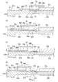
図1は、本発明の第1の実施形態の手術支援装置の構成を示す模式的な部分断面図である。図2は、図1におけるA−A断面図である。図3は、本発明の第1の実施形態の手術支援装置の遮蔽部材の構成を示す模式的な斜視図である。[First Embodiment]
A surgery support apparatus according to a first embodiment of the present invention will be described.
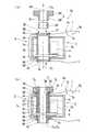
FIG. 1 is a schematic partial cross-sectional view showing the configuration of the surgery support apparatus according to the first embodiment of the present invention. 2 is a cross-sectional view taken along line AA in FIG. FIG. 3 is a schematic perspective view showing the configuration of the shielding member of the surgery support apparatus according to the first embodiment of the present invention.
図1に示すように、本実施形態の手術支援装置100は、例えば、外科手術において術具を患者Pの体腔などの適宜の位置に配置した状態で、術具を操作したり、術具を移動したりするための装置である。
手術支援装置100の概略構成は、術具部支持部101、術具駆動部3(駆動力供給部)、中間部材2、処置具ユニット1(術具部)、およびドレープ7(遮蔽部材)を備え、術具駆動部3と中間部材2、中間部材2と処置具ユニット1とが、矢印Bで示す軸方向にそれぞれ着脱可能に連結されている。これにより、術具駆動部3(駆動力供給部)、中間部材2、および処置具ユニット1は、連結時に全体として基端側から先端側に延びる略軸状の外形を有している。
ここで、手術支援装置100の先端側とは、使用時に患者の体腔に向かう側であり、基端側はその反対側である。
以下では、特に、連結状態の術具駆動部3、中間部材2、および処置具ユニット1(術具部)の長手方向に沿う相対的な位置関係を表す場合には、特に断らない限りは、上記と同様の意味で先端側、基端側、先端部、基端部などと称することにする。
また、中心軸線を特定できる筒状、柱状、軸状等の部材に関する方向を説明する場合、中心軸線に沿う方向を軸方向、中心軸線を中心として周回する方向を周方向、中心軸線に直交する方向を径方向と称する場合がある。As shown in FIG. 1, the
The schematic configuration of the
Here, the distal end side of the
In the following, particularly when representing the relative positional relationship along the longitudinal direction of the connected surgical
In addition, when explaining directions related to members such as cylinders, columns, and shafts that can specify the central axis, the direction along the central axis is the axial direction, the direction around the central axis is the circumferential direction, and the direction orthogonal to the central axis The direction may be referred to as the radial direction.
術具部支持部101は、術具駆動部3を介して処置具ユニット1を着脱可能に支持するもので、本実施形態では、基台101aと、基台101a上に設けられた多関節アーム101bと、多関節アーム101bにおける基台101aと反対側の端部に接続された直動移動部101cとを備える。 The surgical
多関節アーム101bは、図示略のモータ等の駆動部により回転、直動等の多自由度運動が可能な関節に連結されたアームが適宜組み合わされて構成されている。このため、多関節アーム101bを図示略の操作部を操作することにより、基台101aに対する直動移動部101cの位置、姿勢を変更できるようになっている。
多関節アーム101bは、例えば、マスタースレーブ方式の医療用マニピュレータシステムのスレーブアームであってもよい。この場合、術具駆動部3は、医療用マニピュレータシステムの制御部に電気的に接続しマスターアームからの制御信号に基づいた動作を行うようにすることで、スレーブアームの一部を構成することも可能である。The
The
術具部支持部101は、可動部や電気回路を含むため、本実施形態では、術具部支持部101全体としては、例えば、蒸気、熱、圧力、または化学物質などによる滅菌処理(以下、単に滅菌処理と称する)は行っていない。ただし、術具部支持部101において滅菌処理し易いこところは、適宜滅菌処理しておいてもよい。 Since the surgical
術具駆動部3は、図示略の駆動制御部からの制御信号に基づいて、処置具ユニット1を動作させるための変位や力(以下では、簡単のため、まとめて「駆動力」と称する)を発生させ、中間部材2を介して処置具ユニット1に伝達するものである。
本実施形態では、処置具ユニット1をその中心軸線O1回りに回転させる駆動力を供給するものである。
術具駆動部3の概略構成は、直動移動部101cによって一方向に移動可能に支持された支持部3aと、支持部3aに対して一定の中心軸線O3回りに回転可能に支持された軸回転部材3cと、モータ4と、伝動機構5とを備える。The surgical
In the present embodiment, a driving force for rotating the
A schematic configuration of the surgical
支持部3aの形状は、軸回転部材3cを回転可能に支持することができれば、箱状、板状、ブロック状など適宜の形状に形成することができる。
本実施形態では、一例として、箱状に形成され、対向する2側面において同軸となる位置に貫通孔がそれぞれ形成されている。この各貫通孔の内周部にそれぞれ軸受3bの外輪が固定されている。The shape of the
In this embodiment, as an example, a through hole is formed at a position that is formed in a box shape and is coaxial on two opposing side surfaces. The outer ring of the
軸回転部材3cは、各軸受3bの内輪に挿通して固定可能な外径を有し、内部に軸受3bの回転中心軸と同軸となる貫通孔部3dが形成された筒状部材である。軸回転部材3cの長さは、基端部3fと先端部3eとが各軸受3bの内輪に嵌合した状態で、それぞれ支持部3aよりもわずかに外側に突出する程度の長さとされている。
また、図1には特に図示しないが、軸回転部材3cの端部には、軸受3bの内輪と係止または固定するためのフランジ部や固定部材を備えている。
このため、軸回転部材3cは、各軸受3bを介して、支持部3aに回転可能に支持されている。各軸受3bの回転中心軸で規定される軸回転部材3cの回転中心軸を以下では、中心軸線O3と称する。The
Although not particularly shown in FIG. 1, the end portion of the
For this reason, the
支持部3aは、直動移動部101cに対して適宜の姿勢で取り付けることができるが、本実施形態では、一例として、直動移動部101cの移動方向(図1の矢印C参照)と、中心軸線O3とが平行となる姿勢で取り付けている。The
モータ4は、軸回転部材3cに回転駆動力を供給するもので、図示略の駆動制御部と電気的に接続され、この駆動制御部からの制御信号に基づいて回転駆動される。
モータ4のモータ出力軸4aと術具駆動部3との間には、モータ4の回転駆動力を軸回転部材3cに伝達する伝動機構5が設けられている。The
Between the
伝動機構5は、例えば、歯車伝動機構やベルト伝動機構等の適宜の伝動機構を採用することができる。本実施形態では、一例として、図2に示すように、モータ出力軸4aに設けられた駆動プーリ5aと、軸回転部材3cの先端側の外周部に固定された従動プーリ5cと、駆動プーリ5aおよび従動プーリ5cに掛け回された伝動ベルト5bとを備えるベルト伝動機構を採用している。
伝動ベルト5bは、本実施形態では、スリップを起こすことなく回転角度を正確に伝達できるように歯付きベルトを採用している。As the
In this embodiment, the
本実施形態では、術具駆動部3において、モータ4、伝動機構5は、支持部3aによって覆われているものの、支持部3aには軸受3bが露出しているため、術具駆動部3全体としては滅菌処理を行っていない。なお、滅菌処理が容易な部材は適宜滅菌処理してもよい。 In this embodiment, although the
本実施形態では、軸回転部材3cは、処置具ユニット1の姿勢を中心軸線O1回りに回転することによって、処置具ユニット1の回転位置を変更するために設けられている。このため、軸回転部材3cは、異なる方向にそれぞれ少なくとも半回転ずつ回転できればよい。In the present embodiment, the
中間部材2は、術具駆動部3と処置具ユニット1とを着脱可能に連結し、術具駆動部3からの駆動力を、処置具ユニット1側に伝達する部材である。また、中間部材2は、滅菌処理された処置具ユニット1を、滅菌処理されていない術具駆動部3と接触させることなく連結するために設けられている。
中間部材2の概略構成は、図1に示すように、中心軸線O2を中心とする略筒状部材であり、基端側から先端側に向かって基端部2Aと筒状部2Bとが配列されている。The
As shown in FIG. 1, the
基端部2Aは、後述する処置具ユニット1を着脱可能に連結する部分であり、本実施形態では、軸回転部材3cの外径よりも大径の円環状に設けられている。
処置具ユニット1との連結機構は、処置具ユニット1の連結に用いられる周知の連結機構を適宜採用することができる。ただし、中心軸線O2に沿う方向に処置具ユニット1を進退させることで、連結および連結解除を行える連結手段であればより好ましい。
このような好ましい連結手段の一例として、例えばスナップフィットを構成する凹凸係合構造などを挙げることができる。この場合、例えば、一端に第1の係合部を有し弾性変形する棒状の変形部と、第1の係合部と凹凸係合する第2の係合部とが、それぞれ基端部2Aと、処置具ユニット1とに設けられた構成を挙げることができる。ただし、第2の係合部が処置具ユニット1に、変形部が基端部2Aに設けられた構成としてもよい。2 A of base end parts are the parts which connect the
As a connection mechanism with the
As an example of such a preferable connection means, for example, an uneven engagement structure constituting a snap fit can be cited. In this case, for example, a rod-shaped deformable portion that has a first engagement portion at one end and elastically deforms, and a second engagement portion that engages with the first engagement portion in a concavo-convex manner, respectively. And the structure provided in the
筒状部2Bは、軸回転部材3cの貫通孔部3dに貫通して挿入される筒状部分であり、貫通孔部3dと嵌合する形状の挿入外周部2cを備える。
筒状部2Bの長さは、後述するドレープリング6A、6Bと、ドレープリング6C、6Dとが、それぞれ軸回転部材3cを間に挟んだ状態で、これら、ドレープリング6A、6B、軸回転部材3c、およびドレープリング6C、6Dを貫通することができる長さとされている。
ドレープリング6A、6Bは、ドレープ7(遮断部材)を挟み込みこんで固定されており、ドレープリング6A、6Bとドレープ7とには、中間部材2の筒状部2Bが貫通可能な大きさを有する孔部7C(図3参照)が設けられている。
同様に、ドレープリング6C、6Dは、ドレープ7を挟み込みこんで固定されており、ドレープリング6C、6Dとドレープ7とには、中間部材2の筒状部2Bが貫通可能な大きさを有する孔部7D(図3参照)が設けられている。
ドレープ7は、術具駆動部3が設けられた術具部支持部101を、術具駆動部3とともに、処置具ユニット1から遮断するための遮蔽部材であり、滅菌処理されたポリエチレンなどの可撓性を有するシート状部材からなる。The
The length of the
The drape rings 6A and 6B are fixed by sandwiching a drape 7 (blocking member), and the drape rings 6A and 6B and the
Similarly, the drape rings 6C and 6D are fixed by sandwiching the
The
本実施形態では、ドレープリング6C、6Dは、中間部材2の筒状部2Bにより貫通された状態で、中間部材2の基端部2Aと、軸回転部材3cとに挟まれた状態で、筒状部2Bに対して回転自由に位置決めされている。また、ドレープリング6A、6Bは、中間部材2の筒状部2Bにより貫通され、ドレープ7のドレープリング6C、6Dとの位置関係を調節することによって、中間部材2の筒状部2Bから抜け落ちないようにすることができるが、ドレープリング6C、6Dあるいは、中間部材2の筒状部2Bにスナップフィット状の突起を用意して抜け落ちを防止してもよい。 In this embodiment, the drape rings 6C and 6D are penetrated by the
中間部材2の筒状部2Bには、軸回転部材3c内周の軸方向に延びる図示略の溝に対して係合するキー(突起部、図示略)が配置されており、中間部材2と軸回転部材3cは中心軸線O2まわりに挙動を共にする。なお、中間部材2と軸回転部材3cとは、矢印B方向には摺動可能で着脱可能であるが、中間部材2の筒状部2Bの外周面と軸回転部材3cの内周面の摩擦、および重力により、人が意識して抜こうとしない限り簡単に外れてしまうようなことはない。ただし、中間部材2の筒状部2Bの図示しないキーと、軸回転部材3c内周の図示しない溝に配置されたスナップフィットによって、位置を固定してもよい。
また、基端部2Aおよび筒状部2Bの中心部には、処置具ユニット1が挿入可能な術具部挿入孔2dが軸方向に貫通して設けられている。A key (protrusion, not shown) that engages with a groove (not shown) extending in the axial direction of the inner periphery of the
In addition, a surgical instrument
処置具ユニット1は、先端に外科手術に用いる機材、機器である術具1aを有し、中間部材2を介して術具駆動部3から駆動力が伝達されるものであり、中間部材2に対して軸方向に着脱可能に設けられている。
術具1aとしては、例えば、術具部支持部101による移動や術具駆動部3による回転移動のみで、他に外部から駆動力を受けることなく用いることができる機材、機器、例えば、高周波ナイフ等の処置具の例を挙げることができる。ただし、鉗子や、ステープラや、先端部の湾曲動作が可能な内視鏡など、外部から駆動力の供給を受けて、開閉動作や湾曲動作などをする機器を採用することも可能である。
以下では、一例として、術具部支持部101による移動や術具駆動部3による回転移動のみによって使用する機器の場合の例で説明する。The
The
Hereinafter, as an example, an example in the case of a device that is used only by movement by the surgical instrument
中間部材2は、滅菌処理によって劣化する可能性のある可動部や電気回路を有しておらず、全体を滅菌処理している。 The
処置具ユニット1の概略構成は、全体として略軸状であり、中間部材2と連結される連結部1Aと、基端部が連結部1Aと接続され先端部に術具1aを有する軸状部1Bとを備える。 The schematic configuration of the
連結部1Aは、中間部材2の基端部2Aの基端側と着脱可能に連結されている。
軸状部1Bは、中間部材2の術具部挿入孔2dに挿入可能な外径を有し、術具部挿入孔2dを貫通する長さを有している。
連結部1Aおよび軸状部1Bの少なくともいずれかには、貫通孔部3dに対して処置具ユニット1の周方向の位置決めを行うための図示略の係合部が設けられている。1 A of connection parts are connected with the base end side of 2 A of base end parts of the
The shaft-
At least one of the connecting
図3に示すように、ドレープ孔7cの内縁部は、ドレープ7の表面7a(一方の表面)に接合されたドレープリング6A(遮蔽部材、枠部材)と、表面7aの裏面である表面7b(他方の表面)に接合されたドレープリング6B(遮蔽部材、枠部材)とによって挟まれている。ドレープリング6A、6Bはそれぞれ筒状部2Bと挿通可能に嵌合する形状の内周面6a、6bが、互いに同軸の位置に形成されている。
また、ドレープ孔7dの内縁部は、表面7aに接合されたドレープリング6C(遮蔽部材、枠部材)と、表面7bに接合されたドレープリング6D(遮蔽部材、枠部材)とによって挟まれている。ドレープリング6C、6Dはそれぞれ筒状部2Bと挿通可能に嵌合する形状の内周面6c、6dが、互いに同軸の位置に形成されている。
ドレープリング6A、6B、6C、6Dの材質は、例えば、金属、合成樹脂など、ドレープ7に比べて剛性の大きな材質からなり、例えば、接着や融着などによってドレープ7に対して接合されている。As shown in FIG. 3, the inner edge of the
Further, the inner edge portion of the
The material of the drape rings 6A, 6B, 6C, and 6D is made of a material having a rigidity higher than that of the
このような構成により、ドレープリング6A、6Bの内周面6a、6bによって、ドレープ孔7cの孔径以下の内径を有し、筒状部2Bを挿通可能に嵌合する孔部7Cが形成されている。
また、ドレープリング6C、6Dの内周面6c、6dによって、ドレープ孔7dの孔径以下の内径を有し、筒状部2Bを挿通可能に嵌合する孔部7Dが形成されている。
以下では、ドレープリング6A、6B、6C、6Dが接合され、孔部7C、7Dが形成されたドレープ7をドレープ組立体8(遮蔽部材)と称する。
本実施形態では、ドレープ組立体8は、全体として滅菌処理されている。With such a configuration, the inner
Further, the inner
Hereinafter, the
In this embodiment, the
ドレープ組立体8では、ドレープリング6A、6Cの内周面6a、6cを除く表面は、ドレープ7の表面7aに連なる表面になっている。
また、ドレープリング6B、6Dの内周面6b、6dを除く表面は、ドレープ7の表面7bに連なる表面になっている。
ドレープリング6A、6B、6C、6Dは、可撓性を有するドレープ7に形成された変形しやすいドレープ孔7c、7dを覆って、より安定した形状の孔部7C、7Dを形成する枠部材を構成している。In the
The surfaces of the drape rings 6B and 6D other than the inner
The drape rings 6A, 6B, 6C, and 6D are frame members that cover the deformable drape holes 7c and 7d formed in the
孔部7C、7Dの間の距離は、図1に示すように、ドレープ7で術具部支持部101を覆ったときに、術具駆動部3を間に挟んだ状態で、孔部7C、7Dの各中心を、軸回転部材3cの中心軸線O3に整列させることができる寸法にしておく。As shown in FIG. 1, the distance between the
このような構成の手術支援装置100の組立方法について説明する。
図4(a)、(b)は、本発明の第1の実施形態の手術支援装置の組立方法における駆動力供給部設置工程および遮蔽部材配置工程の模式的な工程説明図である。図5(a)、(b)は、本発明の第1の実施形態の手術支援装置の組立方法における第1の連結工程の模式的な工程説明図である。図6は、本発明の第1の実施形態の手術支援装置の組立方法における第2の連結工程の模式的な工程説明図である。A method for assembling the surgical
4A and 4B are schematic process explanatory views of a driving force supply unit installation process and a shielding member arrangement process in the method for assembling the surgery support apparatus according to the first embodiment of the present invention. FIGS. 5A and 5B are schematic process explanatory views of a first connection process in the method for assembling the surgery support apparatus according to the first embodiment of the present invention. FIG. 6 is a schematic process explanatory diagram of a second coupling process in the method for assembling the surgery support apparatus according to the first embodiment of the present invention.
手術支援装置100を組み立てるには、図4(a)に示すように予めドレープ組立体8を形成しておき、その後、駆動力供給部設置工程、遮蔽部材配置工程、第1の連結工程、第2の連結工程、をこの順に行う。 In order to assemble the
駆動力供給部設置工程は、駆動力供給部である術具駆動部3を、術具部支持部101を用いて位置決めする工程である。
このとき、術具駆動部3の姿勢は、術具部支持部101の停止状態に応じた適宜の姿勢で設置することができるが、本実施形態では、予め術具部支持部101の停止状態を調整して、軸回転部材3cの先端部3eが下側に向く状態で、略鉛直方向(鉛直方向を含む)に沿う姿勢となるようにしておく。
以上で、駆動力供給部設置工程が終了する。The driving force supply unit installation step is a step of positioning the surgical
At this time, the posture of the surgical
This completes the driving force supply unit installation process.
次に、遮蔽部材配置工程を行う。本工程は、孔部7C、7Dが設けられたドレープ組立体8の一方の表面である表面7aを、術具部支持部101および術具駆動部3に向けて配置する工程である。
本実施形態では、図4(a)に示すように、表面7aが術具駆動部3および術具部支持部101を向いて、術具駆動部3および術具部支持部101が覆われる適宜位置に配置する。
次に、図4(b)に示すように、ドレープ組立体8を移動して、ドレープリング6Cが軸回転部材3cの基端部3fに近接して対向し、ドレープリング6Aが軸回転部材3cの先端部3eに近接して対向するように、ドレープリング6A、6C等を移動し、孔部7C、7Dの中心を、中心軸線O3に略整列させ(整列させる場合も含む)、この状態を保持する。
これにより、孔部7C、貫通孔部3d、孔部7Dは、この順に略鉛直方向に直列的に配置され、術具駆動部3の外周部がドレープ組立体8によって、縦断面においてC字状をなして覆われる。
以上で、遮蔽部材配置工程が終了する。Next, a shielding member arrangement process is performed. This step is a step of disposing the
In the present embodiment, as shown in FIG. 4A, the
Next, as shown in FIG. 4B, the
Thereby, the
Thus, the shielding member arranging step is completed.
このようにドレープ組立体8が配置されるため、滅菌処理されていない術具駆動部3がドレープ組立体8の表面7aで囲まれた領域に配置されることになる。以下では、この領域を不潔域AU(第1の空間)と称する。
また、ドレープ組立体8の裏面側の表面7bに面する領域を、以下では、清潔域AC(第2の空間)と称する。
本工程終了時においては、不潔域AUと、清潔域ACとは、ドレープ7によって区画されており、孔部7C、7Dによって連通する状態にある。Since the
Moreover, the area | region which faces the
During this step is completed, the unclean area AU, A clean area AC, is partitioned by a
次に、第1の連結工程を行う。本工程は、中間部材2をドレープ組立体8の孔部7C、7Dに挿着するとともに、中間部材2を術具駆動部3に挿着して連結する工程であり、連結後に、中間部材2の第1の表面部がドレープ組立体8の表面7aに連なるとともに中間部材2の第2の表面部がドレープ組立体8の表面7bに連なり、かつ、中間部材2の第1の表面部が術具駆動部3に面するようにする。 Next, a 1st connection process is performed. This step is a step of inserting the
本実施形態では、図5(a)に示すように、ドレープ組立体8が配置された状態で、下方に向けた中間部材2の筒状部2Bを孔部7D上に配置し、この中間部材2を先端側から孔部7D、軸回転部材3cの貫通孔部3d、および孔部7Cに挿入していく。
これにより、ドレープリング6C、6Dは、筒状部2Bの基端側において基端部2Aと軸回転部材3cの基端部3fとの間で挟まれた状態で、筒状部2Bに嵌合される。
また、ドレープリング6A、6Bは、筒状部2Bの先端側において軸回転部材3cの先端部3eと対向した状態で、筒状部2Bに嵌合される。
前述したように、中間部材2の筒状部2Bと軸回転部材3cの貫通孔部3dとは、図示しないキーと溝とにより回転を同一にするように係合されており、軸方向には、中間部材2の基端部2Aにより鉛直下方向にはぬけ落ちず、鉛直上方向には、重力と摩擦力とで人が意識的に抜かない限り抜けることはない。
以上で、第1の連結工程が終了する。In the present embodiment, as shown in FIG. 5 (a), in the state where the
Thereby, the drape rings 6C and 6D are fitted to the
Further, the drape rings 6A and 6B are fitted into the
As described above, the
Thus, the first connecting step is completed.
このような第1の連結工程終了後では、図5(b)に示すように、中間部材2において、ドレープリング6C、6Aに挟まれた挿入外周部2cの表面は、ドレープ7の表面7aに連なる第1の表面部S1を構成している。また、第1の表面部S1は、貫通孔部3dにおいて術具駆動部3の軸回転部材3cに面している。
中間部材2において、ドレープリング6Dより基端側の基端部2Aおよび挿入外周部2cの表面と、術具部挿入孔2dの内周面と、筒状部2Bのドレープリング6Bより先端側の軸回転部材3cの表面とは、ドレープ7の表面7aに連なる第2の表面部S2を構成している。After the completion of the first connecting step, as shown in FIG. 5B, the surface of the insertion outer
In the
このように、本実施形態では、中間部材2に挿着されたドレープ組立体8は、中間部材2の表面領域を2つの異なる領域である第1の表面部S1および第2の表面部S2に分割している。
そして、表面7aと第1の表面部S1は、不潔域AUを覆う表面を構成しており、表面7bと第2の表面部S2とは、清潔域ACを覆う表面を構成している。
このため、第1の連結工程終了後は、中間部材2が、孔部7C、7Dに装着されることで、孔部7C、7Dを通じて連通していた不潔域AUと清潔域ACとは、ドレープ7の最外周面を除けば、互いに連通することのない2領域に区画されている。したがって、ドレープ7の大きさを、術具駆動部3および術具部支持部101に合わせて充分大きくしておけば、術具駆動部3および術具部支持部101を不潔域AUに隔離し、清潔域ACから遮蔽することができる。
したがって、本工程は、ドレープ組立体8の孔部7C、7Dおよび中間部材2を係合させて、ドレープ組立体8と中間部材2とからなる組立体を形成し、この組立体を境界とする第1の空間に、術具駆動部3および術具部支持部101を位置させ、第1の空間の側において、中間部材2と術具部支持部101とを着脱可能に連結する工程になっている。Thus, in the present embodiment, the
Then, the
Therefore, after the completion of the first coupling step, the
Accordingly, in this step, the
次に、第2の連結工程を行う。本工程は、清潔な処置具ユニット1を、中間部材2の第2の表面部S2において中間部材2と連結する工程である。
第1の連結工程終了後、中間部材2の術具部挿入孔2dは、清潔域AC内に突出した不潔域AU内に、不潔域AUと連通しない状態で貫通し、清潔域ACの一部を構成する円柱状に広がる清潔域aC(図6参照)が形成されている。
本工程では、まず、図6に示すように、処置具ユニット1を術具1aが下方に向くように中間部材2の上方に保持する。このとき、滅菌処理済みの処置具ユニット1は、術具駆動部3の上方の清潔域ACに位置している。
次に、処置具ユニット1を、術具1a側から中間部材2の基端側(図6の上側)の術具部挿入孔2dに軸状部1Bを挿入し、術具1aを先端側まで貫通させる。このとき、術具1aおよび軸状部1Bは、術具駆動部3の上側の清潔域ACから、清潔域aCを通って、術具駆動部3の下側の清潔域ACに移動する。
そして、図1に示すように、連結部1Aを中間部材2の基端部2Aと連結する。その際、軸状部1Bは、術具部挿入孔2dと接触し、摺動移動するが、術具部挿入孔2dは、滅菌処理済みであるため、中間部材2によって処置具ユニット1が汚染されることはない。
以上で、第2の連結工程が終了する。
したがって、本工程は、ドレープ組立体8と中間部材2とからなる組立体を境界として第1の空間と反対側の第2の空間の側において、中間部材2と処置具ユニット11とを着脱可能に保持させる工程になっている。Next, a 2nd connection process is performed. In this step, clean
After completion the first coupling step, surgical instrument
In this step, first, as shown in FIG. 6, the
Next, the
Then, as shown in FIG. 1, the connecting
With the above, the second connecting step is completed.
Therefore, in this process, the
このようにして、手術支援装置100を組み立てることができる。 In this way, the
また、手術支援装置100では、上述の第2の連結工程を逆の順に行うことにより、処置具ユニット1を連結解除し、処置具ユニット1を、術具駆動部3および中間部材2の上方側(軸回転部材3cおよび中間部材2の基端側)に引き抜いて取り外すことができる。
このように、本実施形態では、処置具ユニット1を、中間部材2の上方から連結することができ、処置具ユニット1は、術具部挿入孔2dよりも大径の基端部2Aによって、基端側で連結されているため、中間部材2の連結を解除しても、下方に抜け落ちることがない。このため、患者P上に術具駆動部3を位置付けた状態のままでも、術具駆動部3よりも上方のスペースを有効利用して、容易に処置具ユニット1を着脱することができる。Further, in the
Thus, in this embodiment, the
次に、手術支援装置100の動作について説明する。
手術支援装置100は、多関節アーム101bによって直動移動部101cの位置および姿勢を変化させ、患者Pに対する適宜の姿勢に術具駆動部3を保持することができる。
またその姿勢で、直動移動部101cを駆動することにより、術具駆動部3を直動移動させることができる。本実施形態では、中心軸線O3に平行な方向に移動できる。このため、例えば、術具部支持部101により術具1aを患者Pに向かう方向に位置付けて、直動移動部101cを駆動することにより、術具駆動部3に支持された術具1aを患者Pに向かって、進退移動させることができる。
また、術具部支持部101を駆動することにより術具1aを患者P上および患者Pの体腔内で、多自由度の移動を行うことができる。これにより、例えば術具1aが高周波ナイフの場合に、術具1aを患者Pに対して相対移動させることで、生体組織を切除したりすることができる。Next, operation | movement of the
The
In addition, by driving the linear
Further, by driving the surgical
また、術具駆動部3は、モータ4の回転駆動力を、伝動機構5によって軸回転部材3cに伝達することができる。このため、軸回転部材3c、軸回転部材3cに連結された中間部材2、および中間部材2に連結された処置具ユニット1を、中心軸線O3、およびこれと同軸の中心軸線O2、O1回りに回転駆動することができる。
このため、術具1aの中心軸線O1回りの角度を適宜変更し、術具1aの向きを変えることができる。
なお、このような回転時に中間部材2とドレープリング6D、6C、6B、6Aとは軸O1に対して回転自在なため、ドレープ組立体8に影響を与えない。また、摩擦によってドレープリング6D、6C、6B、6Aが中間部材2に対して連れ回ったとしても、柔らかい素材からなるドレープ7は、回転に対してほとんど抵抗なく追従して変形する。このため、回転および術具1aの作業の支障とはならない。Further, the surgical
Therefore, the central axis O1 about the angle of the
Note that such rotation when the
このような手術支援装置100によれば、滅菌処理されていない術具駆動部3、術具部支持部101をドレープ組立体8で遮断して、術具駆動部3および術具部支持部101を清潔域ACと連通しない不潔域AUに隔離することができるため、滅菌処理しなくても、手術室などで使用することが可能である。
このため、術具駆動部3および術具部支持部101の構成部品として、滅菌処理が困難、もしくは滅菌することにより劣化しやすい可動部品や電機部品などの部品を採用することが可能であり、これにより、術具駆動部3および術具部支持部101を低コスト化したり、長寿命化したりすることができる。
例えば、軸受3bは、滅菌処理に対する耐性が強い高価な軸受を用いなくてもよく、また、滅菌処理によって軸受3bが劣化することがない。このため、頻繁に交換する必要もないため、術具駆動部3を安価に構成することができる。
また、一般的に使い捨てになる柔軟なドレープ7と動力伝達を担う中間部材を分離し、中間部材を繰り返し滅菌可能とすることにより、使い捨て部品のコストが低減することができる。According to such a surgical
For this reason, as a component of the surgical
For example, the
Moreover, the cost of a disposable part can be reduced by isolate | separating the intermediate member which bears the
また、術具駆動部3は、一例として、モータ4、伝動機構5を箱状の支持部3aによって覆う構成として説明したが、術具駆動部3を全体として滅菌処理する必要がないため、モータ4や伝動機構5を滅菌処理から防護するために支持部3aを箱状に形成する必要はない。このため、支持部3aとして、モータ4や伝動機構5が覆われていない板状部材やブロック状部材から構成することもできる。 Further, the surgical
また、本実施形態の手術支援装置100の組立方法によれば、処置具ユニット1を清潔域ACに配置した状態で、術具駆動部3と接触することなく、滅菌処理された中間部材2と着脱できるため、手術室内での処置具ユニット1の交換を迅速かつ容易に行うことができる。
例えば、手術室内で、複数の手術が行われる場合、手術の種類や患者Pに応じて、処置具ユニット1を交換するが、術具駆動部3、術具部支持部101は、清潔域ACからは隔離され、処置具ユニット1とは接触しないため、交換や移動をすることなく、続けて用いることができる。Further, according to the assembly method of the
For example, when a plurality of operations are performed in the operating room, the
[第1変形例]
次に、本実施形態の変形例(第1変形例)の手術支援装置について説明する。
図7は、本発明の第1の実施形態の変形例(第1変形例)の手術支援装置の主要部の構成を示す模式的な部分断面図である。[First Modification]
Next, a surgery support apparatus according to a modification (first modification) of the present embodiment will be described.
FIG. 7 is a schematic partial cross-sectional view illustrating a configuration of a main part of a surgical operation support apparatus according to a modified example (first modified example) of the first embodiment of the present invention.
本変形例の手術支援装置110は、図7に示すように、上記第1の実施形態の手術支援装置100のドレープ組立体8、術具駆動部3、中間部材2、処置具ユニット1に代えて、それぞれ、ドレープ組立体18(遮蔽部材)、術具駆動部13(駆動力供給部)、中間部材12、処置具ユニット11(術具部)を備える。
術具駆動部13は、上記第1の実施形態の術具駆動部3の軸回転部材3cを軸回転部材13cに代えたものである。
また、ドレープ組立体18、中間部材12、および処置具ユニット11は、滅菌処理されており、術具駆動部13は滅菌処理されていない。
以下、上記第1の実施形態と異なる点を中心に説明する。As shown in FIG. 7, the surgical
The surgical
Further, the
Hereinafter, a description will be given centering on differences from the first embodiment.
ドレープ組立体18は、上記第1の実施形態のドレープ組立体8のドレープリング6C、6D、孔部7Dを削除したものである。このため、ドレープ組立体18は、孔部として、孔部7Cのみを有する例になっている。 The
軸回転部材13cは、上記第1の実施形態の軸回転部材3cの基端部3fの開口を閉止し、先端部3eのみが開口する有底円筒状の部材としたものである。このため、先端部3eの中心部には貫通孔部3dに代えて、中心軸線O3と同軸な挿入穴部13dが形成されている。The
中間部材12は、術具駆動部13と処置具ユニット11とを着脱可能に連結し、術具駆動部13からの駆動力を、処置具ユニット11側に伝達する部材である。また、中間部材12は、滅菌処理された処置具ユニット11を、滅菌処理されていない術具駆動部3と接触させることなく連結するために設けられている。
中間部材12の概略構成は、図7に示すように、中心軸線O12を中心とする略筒状部材であり、基端側から先端側に向かって挿入連結部12Aと先端部12Bとが配列されている。The
A schematic configuration of the
挿入連結部12Aは、後述する処置具ユニット11を着脱可能に連結する部分であり、本変形例では、軸回転部材13cの挿入穴部13dに先端側(図7の下側)から挿入される円柱状の外形を有する部分であり、外周部に挿入穴部13dと着脱可能に嵌合する形状の挿入外周部12cを備える。
挿入外周部12cと、挿入穴部13dとは、互いに着脱可能であって、軸方向および周方向の相対位置を固定する図示略の連結構造、例えば、スナップフィットや磁石などが設けられている。The
The insertion outer
先端部12Bは、軸回転部材13cと連結された挿入連結部12Aの先端側において、軸回転部材3cの先端部3eと対向する円環状の部分である。
先端部12Bの中心部には、処置具ユニット11の基端部を挿入して保持するため、術具部挿入穴12dが設けられている。本変形例では、術具部挿入穴12dは、先端部12Bの先端側から挿入連結部12Aの内部側に向かって、挿入外周部12cの中心軸線O12と同軸に形成された穴部からなる。
このため、中間部材12は、先端側に術具部挿入穴12dが開口し、基端側が閉止された有底筒状の形状を有する。The
In the center of the
For this reason, the
先端部12Bの基端側には、軸回転部材13cとの連結時に、軸回転部材13cの先端部3eとの間に、ドレープリング6A、6Bを固定する図示略のドレープリング固定部が設けられている。ドレープリング固定部としては、上記第1の実施形態と同様の構成を採用することができる。
また、先端部12Bの先端側には、術具部挿入穴12dに挿入した処置具ユニット11の軸方向および周方向の位置を固定して着脱可能に連結する図示略の連結部が設けられている。連結部としては、例えば、コレットチャックなどを採用することができる。A drape ring fixing portion (not shown) that fixes the drape rings 6A and 6B is provided between the
Further, on the distal end side of the
処置具ユニット11は、先端に術具1aを有し、中間部材12を介して術具駆動部13から伝達される駆動力が伝達されるものであり、中間部材12に対して軸方向に着脱可能に設けられている。
処置具ユニット11の概略構成は、全体として略軸状であり、基端側に、中間部材12の術具部挿入穴12dに挿入される基端側挿入部11Aが形成され、基端側挿入部11Aと術具1aとの間に、軸状部11Bが設けられている。
軸状部11Bにおいて、中間部材12との連結時に中間部材12の先端部12Bの近傍となる位置に、中間部材12に対する軸方向および周方向の位置を固定して連結する図示略の連結部が設けられている。The
The overall configuration of the
In the shaft-
このような構成の手術支援装置110は、上記第1の実施形態と略同様にして組み立てることができる。
すなわち、予めドレープ組立体18を形成しておき、駆動力供給部設置工程、遮蔽部材配置工程、第1の連結工程、第2の連結工程、をこの順に行う。以下、上記第1の実施形態と異なる点を中心に説明する。The surgical
That is, the
本変形例の駆動力供給部設置工程は、術具駆動部3に代えて、術具駆動部13を術具部支持部101に設置する工程であり、上記第1の実施形態と同様の工程である。 The driving force supply unit installation step of the present modification is a step of installing the surgical
本変形例の遮蔽部材配置工程は、ドレープ組立体18では孔部7Dが削除されているため、ドレープ組立体18を術具駆動部13に向けて移動する際、ドレープリング6Aを軸回転部材13cの先端部3eに近接して配置し、孔部7Cの中心を中心軸線O3に略整列させる点が異なる。In the shielding member arranging step of this modification, since the
本変形例の第1の連結工程は、中間部材12をドレープ組立体18の孔部7Cに挿着するとともに、中間部材12を術具駆動部13に連結する工程であり、連結後に、中間部材12の第1の表面部がドレープ組立体18の表面7aに連なるとともに中間部材12の第2の表面部がドレープ組立体18の表面7bに連なり、かつ、中間部材12の第1の表面部が術具駆動部13に面するようにする。
本変形例では、前工程でドレープ組立体18が配置された状態で、上方に向けた中間部材12の挿入連結部12Aを孔部7Cの下方に配置し、この中間部材12を基端側から孔部7C、軸回転部材13cの挿入穴部13dに挿入していく。
これにより、図7に示すように、ドレープリング6A、6Bは、先端部12Bの基端側において軸回転部材13cの先端部3eと対向した状態で、挿入連結部12Aの先端側に嵌合される。
この状態で、中間部材12と術具駆動部13、および中間部材12とドレープリング6A、6Bをそれぞれ連結する。
以上で、本変形例の第1の連結工程が終了する。The first connecting step of this modification is a step of inserting the
In this modified example, in a state where the
Accordingly, as shown in FIG. 7, the drape rings 6A and 6B are fitted to the distal end side of the
In this state, the
This is the end of the first connecting step of this modification.
このような第1の連結工程終了後では、図7に示すように、中間部材12において、ドレープリング6Cよりも基端側の挿入外周部12cの表面は、ドレープ7の表面7aに連なる第1の表面部T1を構成している。また、第1の表面部T1は、挿入穴部13dにおいて術具駆動部13の軸回転部材13cに面している。
中間部材12において、ドレープリング6Aより先端側の先端部12Bと、術具部挿入穴12dの内面とは、ドレープ7の表面7aに連なる第2の表面部T2を構成している。After the completion of the first connecting step, as shown in FIG. 7, in the
In the
本変形例では、中間部材12に挿着されたドレープ組立体18は、中間部材12の表面領域を2つの異なる領域である第1の表面部T1および第2の表面部T2に分割している。
そして、表面7aと第1の表面部T1は、不潔域AUを覆う表面を構成しており、表面7bと第2の表面部T2とは、清潔域ACを覆う表面を構成している。
このため、上記第1の実施形態と同様に、ドレープ組立体18は、術具駆動部13および術具部支持部101を不潔域AUに隔離し、清潔域ACから遮蔽している。In this modification, the
Then, the
Therefore, as in the first embodiment, the
本変形例の第2の連結工程は、処置具ユニット11を、中間部材12の第2の表面部T2において中間部材12と連結する工程である。
第1の連結工程終了後、中間部材12の術具部挿入穴12dは、清潔域AC内に突出した不潔域AU内に、不潔域AUと連通しない状態で突出し、清潔域ACの一部を構成している。
本工程では、処置具ユニット11を術具1aが下方に向くように中間部材12の下方に保持する。このとき、滅菌処理済みの処置具ユニット11は、術具駆動部13の下方の清潔域ACに位置している。
次に、処置具ユニット11の基端側挿入部11Aを、中間部材12の術具部挿入穴12dに挿入し、先端部12Bにおいて、処置具ユニット11と連結する(図7参照)。
その際、基端側挿入部11Aは、術具部挿入穴12dと接触し、摺動移動するが、術具部挿入穴12dは、滅菌処理済みであるため、中間部材12によって処置具ユニット11が汚染されることはない。
以上で、第2の連結工程が終了する。
このようにして、手術支援装置110を組み立てることができる。Second coupling step of this modification, the
After completion the first coupling step, surgical instrument
In this step, the
Next, the proximal end
At this time, the proximal end
With the above, the second connecting step is completed.
In this way, the
このような手術支援装置110によれば、上記第1の実施形態と同様に、滅菌処理されていない術具駆動部13、術具部支持部101をドレープ組立体18で遮断して、術具駆動部13および術具部支持部101を清潔域ACと連通しない不潔域AUに隔離することができるため、滅菌処理しなくても、手術室などで使用することが可能である。
また、術具駆動部13および術具部支持部101を低コスト化したり、長寿命化したりすることができる。
また、本変形例の手術支援装置110の組立方法によれば、処置具ユニット11を清潔域ACに配置した状態で、術具駆動部13と接触することなく、滅菌処理された中間部材12と着脱できるため、手術室内での処置具ユニット11の交換を迅速かつ容易に行うことができる。According to such a surgical
In addition, the surgical
Further, according to the assembly method of the
[第2の実施形態]
次に、本発明の第2の実施形態の手術支援装置について説明する。本実施形態は、術具駆動部から中間部材を介して処置具ユニットの術具先端を駆動する動力を伝達する場合の実施形態である。
図8は、本発明の第2の実施形態の手術支援装置の主要部の外観を示す模式的な斜視図である。図9は、本発明の第2の実施形態の手術支援装置の主要部の連結時の軸方向に沿う模式的な断面図である。図10は、本発明の第2の実施形態の手術支援装置の主要部の連結解除時の軸方向に沿う模式的な断面図である。図11は、本発明の第2の実施形態の手術支援装置の術具部駆動部と中間部材との連結時の軸方向に沿う模式的な断面図である。図12は、本発明の第2の実施形態の手術支援装置の詳細構成を示す軸方向に沿う模式的な断面図である。図13は、図12におけるP部の部分拡大図である。図14は、本発明の第2の実施形態の手術支援装置の軸固定部材係合部と第2の軸係合部との係合した様子を示す軸方向に沿う模式的な断面図である。図15は、本発明の第2の実施形態の手術支援装置の術具部および中間部材の主要部の構成を示す軸方向に沿う模式的な断面図、およびQ部の部分拡大図である。[Second Embodiment]
Next, a surgery support apparatus according to a second embodiment of the present invention will be described. The present embodiment is an embodiment in the case where power for driving the surgical instrument tip of the treatment instrument unit is transmitted from the surgical instrument drive unit via the intermediate member.
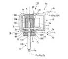
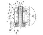
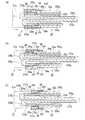
FIG. 8 is a schematic perspective view showing the appearance of the main part of the surgery support apparatus according to the second embodiment of the present invention. FIG. 9 is a schematic cross-sectional view along the axial direction when the main parts of the surgery support apparatus according to the second embodiment of the present invention are connected. FIG. 10 is a schematic cross-sectional view along the axial direction when the main part of the surgery support apparatus according to the second embodiment of the present invention is disconnected. FIG. 11: is typical sectional drawing in alignment with the axial direction at the time of the connection of the surgical instrument part drive part and intermediate member of the surgery assistance apparatus of the 2nd Embodiment of this invention. FIG. 12: is typical sectional drawing which follows the axial direction which shows the detailed structure of the surgery assistance apparatus of the 2nd Embodiment of this invention. FIG. 13 is a partial enlarged view of a portion P in FIG. FIG. 14 is a schematic cross-sectional view along the axial direction showing a state where the shaft fixing member engaging portion and the second shaft engaging portion of the surgery support apparatus according to the second embodiment of the present invention are engaged. . FIG. 15 is a schematic cross-sectional view along the axial direction showing the configuration of the main part of the surgical instrument part and the intermediate member of the surgery support apparatus according to the second embodiment of the present invention, and a partially enlarged view of the Q part.
本実施形態の手術支援装置120は、図1に示すように、上記第1の実施形態の手術支援装置100の術具駆動部3、中間部材2、処置具ユニット1に代えて、それぞれ、術具駆動部23(駆動力供給部)、中間部材22、術具部21を備える。
また、中間部材22、および術具部21は、滅菌処理されており、術具駆動部23は滅菌処理されていない。
以下、上記第1の実施形態と異なる点を中心に説明する。As shown in FIG. 1, the
The
Hereinafter, a description will be given centering on differences from the first embodiment.
図8に示すように、手術支援装置120は、術具駆動部23と中間部材22、中間部材22と術具部21とが、矢印Dで示す軸方向にそれぞれ着脱可能に連結されている。これにより、手術支援装置120は全体として基端側から先端側に延びる略軸状の外形を有している。
以下では、各部の概略形状や位置関係を説明してから、それぞれの連結構造について説明する。As shown in FIG. 8, in the
Below, after demonstrating the schematic shape and positional relationship of each part, each connection structure is demonstrated.
術具駆動部23は、図示略の駆動制御部からの制御信号に基づいて、術具部21を動作させるための変位や力(以下では、簡単のため、まとめて「駆動力」と称する)を発生させ、術具部21に伝達するものである。駆動力の伝達経路は間接的であってもよいし、直接的であってもよい。本実施形態では、後述するように、中間部材22の中間軸22bを介して間接的に伝達される。
術具駆動部23は、図9、10に示すように、術具駆動部支持体23aを備え、術具駆動部支持体23aの内部には、モータ部25、直動変換部24、および駆動力伝達軸23bを備え、さらに上記第1の実施形態と同様に、モータ4、伝動機構5を備える。The surgical
As shown in FIGS. 9 and 10, the surgical
なお、図9、10は、連結関係を簡素化して模式的に示しており、細部形状は適宜省略されたり誇張されたりしている。例えば、駆動力伝達軸23bの端部は連結端部C32と整列した位置に描かれているが、実際の連結動作においては、後述するように、中間部材22側に突出されている。9 and 10 schematically show the connection relationship in a simplified manner, and the detailed shape is omitted or exaggerated as appropriate. For example, the end portion of the driving
術具駆動部支持体23aは、内部に中間部材22を挿通可能とする貫通孔部23dを有する筒状部23cと筒状部23cの基端側に径方向側に張り出す円環部23gを設けた軸回転部材23Aと、円環部23gの外周部において軸受35aを介して軸回転部材23Aを回転可能に保持する側板部23Bと、筒状部23cの先端側において、軸受35bを介して軸回転部材23Aを回転可能に保持する側板部23Dと、これらの側板部23B、23Dの外周側に接合され、術具駆動部支持体23aの外周側を覆う筐体23Cとを備える。
側板部23B、23Dにおける軸受35a、35bは、上記第1の実施形態の軸受3bと同様に、軸回転部材23Aの回転中心軸を規定する。この回転中心軸は、以下、中心軸線O23と称する。The surgical instrument
The
術具駆動部支持体23aにおいて、軸回転部材23Aの外周部、側板部23B、23D、および筐体23Cで囲まれた術具駆動部支持体23aの内部には、各直動変換部24、各モータ部25が固定されている。
側板部23Dには、モータ4が設置され、伝動機構5を介して、軸回転部材23Aの筒状部23cの外周部に固定された従動プーリ5cを介して、軸回転部材23Aを、中心軸線O23回りに回転させることができるようになっている。
軸回転部材23Aの円環部23gの基端側には、図10に示すように、連結時に中間部材22と接する連結端部C32が形成されている。In the surgical instrument
The
The base end side of the
なお、図9、10は、連結関係を簡素化して模式的に示しており、細部形状は適宜省略されたり誇張されたりしている。例えば、駆動力伝達軸23bの端部は連結端部C32と整列した位置に描かれているが、実際の連結動作においては、後述するように、中間部材22側に突出されることもある。9 and 10 schematically show the connection relationship in a simplified manner, and the detailed shape is omitted or exaggerated as appropriate. For example, the end portion of the driving
モータ部25は、図示略の駆動制御部からの制御信号に基づいて回転駆動されるモータであり、図示略の出力軸は直動変換部24に連結されている。モータ部25の具体的な構成としては、例えば、DCモータなどを採用することができる。
直動変換部24は、モータ部25の回転出力を、貫通孔部23dの中心軸線O23に沿う方向の直動運動に変換するものである。直動変換部24の構成としては、回転運動を直動運動に変換できれば特に限定されないが、例えば、送りねじ機構などの例を挙げることができる。
駆動力伝達軸23bは、直動変換部24によって直動駆動される軸部材であり、術具駆動部支持体23aの内部において、中心軸線O23から径方向に離間した位置で、中心軸線O23に平行な方向に移動可能に支持されている。
また、駆動力伝達軸23bは、連結端部C32の近傍に配置され、必要に応じて、連結端部C32よりも中間部材22側に突出したり、術具駆動部23側に退避したりすることが可能である。本実施形態では、図12に示すように、駆動力伝達軸23bの端部は中間部材22側に突出した状態で連結されている。
駆動力伝達軸23bの軸方向に直交する断面の形状は特に限定されないが、例えば、矩形状断面を採用することができる。The
Linear
Driving
The driving
Although the shape of the cross section orthogonal to the axial direction of the driving
駆動力伝達軸23b、直動変換部24、およびモータ部25の各個数は、術具部21の駆動に必要な駆動入力数に応じて1以上の適宜数に設定することができる。
以下では、図10に示すように、一例として、中心軸線O23を挟んで線対称となる位置関係に同様な構成を有する一対のものが設けられている場合の例で説明する。
このため、各図面では、同形状の部材が中心軸線O23等の中心軸線を挟んで線対称に設けられていることが明らかな場合には、図面を見易くするため、片方の符号を省略したり、一部材に含まれる符号を対称な二部材に分けて記載したりする場合がある。The number of each of the driving
In the following, as shown in FIG. 10, as an example, a description will be given of an example in which a pair having a similar configuration is provided in a positional relationship that is symmetric with respect to the central axis O23 .
For this reason, in each drawing, when it is clear that the members having the same shape are provided symmetrically with respect to the central axis such as the central axis O23 , the reference numeral on one side is omitted for easy understanding of the drawings. Or a code included in one member may be divided into two symmetrical members.
中間部材22は、術具駆動部23と術具部21とを着脱可能に連結し、術具駆動部23からの駆動力を、術具部21側に伝達する部材である。また、中間部材22は、滅菌処理された術具部21を、滅菌処理されていない術具駆動部23と接触させることなく連結するために設けられている。
中間部材22の概略構成は、図10に示すように、中心軸線O22を中心とする略筒状部材であり、基端側から先端側に向かって連結部22Aと筒状部22Bとが配列された中間部材支持体22a(第1の支持体)と、術具駆動部23の各駆動力伝達軸23bとそれぞれ着脱可能に係合され、係合時に各駆動力伝達軸23bからの駆動力を受けて術具部21側に伝達する駆動力伝達軸23bと同数の中間軸22b(中間軸部、第1の軸部)とを備える。The
As shown in FIG. 10, the schematic configuration of the
連結部22Aは、連結時に術具駆動部23の連結端部C32と軸方向に接する連結端部C23と、この連結端部C23と反対側の基端部に形成され連結時に術具部21と軸方向に接する連結端部C21とで挟まれた円環状の領域内に広がる支持体部分である。
連結部22Aの内部には、各中間軸22bを周方向および径方向の位置に位置決めして保持するとともに軸方向に摺動可能に保持するガイド溝22gが、連結端部C23から連結端部C21に向かって貫通して形成されている。
このガイド溝22gによって、各中間軸22bは、連結時に術具部21の各入力側伝達軸部21Aと対向するとともに、術具駆動部23の各駆動力伝達軸23bとも対向可能な位置に位置決めされる。
なお、図示は省略するが、連結部22Aには、術具駆動部23、術具部21に対して中間部材22の周方向の位置決めを行うため、適宜の位置決め部が設けられている。Connecting
Inside the connecting
By the
In addition, although illustration is abbreviate | omitted, in order to perform the circumferential positioning of the
筒状部22Bは、術具駆動部支持体23aの貫通孔部23dに貫通して挿入される筒状の支持体部分であり、貫通孔部23dと嵌合する形状の挿入外周部22cを備える。
連結部22Aおよび筒状部22Bの中心部には、術具部21が挿入可能な術具部挿入孔22dが軸方向に貫通して設けられている。The
A surgical instrument
中間軸22bの軸方向に直交する断面の形状は、特に限定されないが、本実施形態では、一例として中間部材22の径方向において2辺が対向する矩形断面を採用している。 The shape of the cross section orthogonal to the axial direction of the
中間部材22と術具駆動部23との間には、図9に示すように、中間部材支持体22aおよび術具駆動部支持体23aを着脱可能に係合する支持体着脱機構部32Bと、中間軸22bおよび駆動力伝達軸23bを着脱可能に係合する軸着脱機構部32Aとが設けられている。
支持体着脱機構部32Bの具体的な構成は、本実施形態では、図12に示すように、軸回転部材23Aの基端部に中間部材支持体22aを当接した状態で、図示略の係合部に係合させてからロックする周知の固定リング34によって固定する構成を採用している。
ただし、固定リング34によって係合を固定する際、中間部材支持体22aの先端側の端部の外周部にドレープ組立体8のドレープリング6C、6Dを外嵌させ、ドレープリング6C、6Dを術具駆動部23との間に介在させた状態で固定している。
また、中間部材22の筒状部22Bの先端側には、ドレープ組立体8のドレープリング6A、6Bが固定されている。Between the
In the present embodiment, the specific structure of the support attaching /
However, when the engagement is fixed by the fixing
Further, the drape rings 6A and 6B of the
このため、図11に示すように、中間部材22においても、上記第1の実施形態と同様に、ドレープリング6C、6Aに挟まれた挿入外周部22cの表面は、ドレープ7の表面7aに連なる第1の表面部S1を構成している。このため、連結時には、第1の表面部S1は、貫通孔部23dにおいて軸回転部材23Aと面することになる。
中間部材22において、ドレープリング6Dより基端側の連結部22Aおよび挿入外周部22cの表面と、術具部挿入孔22dの内周面と、筒状部22Bのドレープリング6Bより先端側の軸回転部材23Aの表面とは、ドレープ7の表面7aに連なる第2の表面部S2を構成している。
すなわち、手術支援装置120において、術具駆動部23は、ドレープ7の一方の表面7aによって覆われた不潔域AUに配置され、術具部21は、表面7aの裏面側である表面7bに面しており、ドレープ7および中間部材22を境界として不潔域AUから隔てられた清潔域ACに配置される。For this reason, as shown in FIG. 11, also in the
In the
That is, in the
軸着脱機構部32Aは、本実施形態では、図12に示すように、軸係合部23eと、軸係合部22eとからなる構成を採用している。
軸係合部23eは、術具駆動部23において基端側となる、駆動力伝達軸23bの端部に形成されている。
軸係合部22eは、中間部材22において先端側となる、中間軸22bの端部に形成され軸係合部23eと着脱可能に係合できるようになっている。
軸係合部23e、22eの具体的な構成は、互いに着脱可能に係合する凹凸部等からなる周知の構成を適宜採用することが可能である。In this embodiment, the shaft attaching /
The
The
As a specific configuration of the
術具部21は、図10に示すように、先端側に、操作対象を操作する術具である作動部21cを有し、中間部材22を介して術具駆動部23から伝達される駆動力によって作動部21cを駆動して、操作対象を操作するものであり、中間部材22に対して軸方向に着脱可能に設けられている。
術具部21の作動部21cは、1軸方向に沿う1以上の駆動力によって動作可能な構成であれば、適宜の構成を採用することができる。例えば、2個の鉗子片からなる鉗子や、鉗子の向きを変える関節や、ステープラや、1方向または2方向に湾曲可能な内視鏡の湾曲部などの構成を採用することができる。As shown in FIG. 10, the
As long as the operation |
術具部21の概略構成は、図10に示すように、全体として略軸状であり、中間部材22と連結される術具部支持体21a(第2の支持体)と、中間部材22の中間軸22bと着脱可能に係合され、係合時に各中間軸22bからの駆動力を受けて作動部21c側に伝達する中間軸22bと同数の駆動力伝達部材21bとを備える。 As shown in FIG. 10, the schematic configuration of the
術具部支持体21aは、連結時に中間部材22の連結端部C21と接する連結端部C12を有し、内部に駆動力伝達部材21bの一部を連結時に中間軸22bの移動方向と同方向に移動可能に支持する箱状部21eと、箱状部21eの中心軸線O21と同軸で、先端側に延ばされた筒状部21dが形成されている。
箱状部21eの連結端部C12側の内部には、各駆動力伝達部材21bの一端部を軸方向に摺動可能に保持するガイド溝21gが形成されている。
このガイド溝21gによって、各駆動力伝達部材21bは、連結時に中間部材22の各中間軸22bと対向可能な周方向および径方向の位置に位置決めされる。
筒状部21dは、中間部材22の術具部挿入孔22dに挿入可能な外径を有するとともに、術具部挿入孔22dよりも長くなっている。筒状部21dの先端部には、作動部21cが接続されている。Surgical
Inside the connection end C12 side of the box-shaped
Each guide
The
駆動力伝達部材21bは、略J字状に屈曲した形状を有する軸状部材であり、入力側伝達軸部21A(術具部軸部、第2の軸部)、連結部21B、および出力側伝達軸部21Cを備える。 The driving
入力側伝達軸部21Aは、中間軸22bと係合可能に設けられ、中間軸22bとの係合時に、中間軸22bからの駆動力を受ける軸部であり、箱状部21eのガイド溝21gによって中心軸線O21と平行な軸方向に移動可能に保持されている。
入力側伝達軸部21Aの軸方向に直交する断面の形状は、特に限定されないが、本実施形態では、一例として術具部21の径方向において2辺が対向する矩形断面を採用している。The input side
The shape of the cross section perpendicular to the axial direction of the input side
連結部21Bは、入力側伝達軸部21Aの基端側の端部から中心軸線O21に向かって形成され出力側伝達軸部21Cの基端側の端部と入力側伝達軸部21Aの基端側の端部とを連結している部分である。
本実施形態では、図12に示すように(図9、10では図示略)、連結部21Bの基端側には、径方向外側に突出する段状突起部21mが設けられ、この段状突起部21mの径方向の端部に、後述する棒状部29Cの係合突起29cを係合するための係合凹部21j(第2の軸係合部)が設けられている。Connecting
In the present embodiment, as shown in FIG. 12 (not shown in FIGS. 9 and 10), a stepped
出力側伝達軸部21Cは、中心軸線O21と平行な姿勢で連結部21Bから術具部21の先端側に延ばされた軸部であり、箱状部21eおよび筒状部21dの内部に収容され、先端部が作動部21cと連結されている。
出力側伝達軸部21Cは、例えば、ロッドやワイヤなど、作動部21cを操作可能な適宜の部材を採用することができる。出力側伝達軸部21Cは、作動部21cが内視鏡の湾曲部などである場合、可撓性を有して湾曲可能な軸部を採用してもよい。Output
For the output side
駆動力伝達部材21bは、入力側伝達軸部21A、連結部21B、出力側伝達軸部21Cにそれぞれ適した別材料で形成した複数部材を適宜接合して形成することができるが、一体成形されていてもよい。 The driving
術具部21と中間部材22との間には、図9に示すように、入力側伝達軸部21Aおよび中間軸22bを着脱可能に係合する軸着脱機構部31Aと、術具部支持体21aおよび中間部材支持体22aを着脱可能に係合する支持体着脱機構部31Bとが設けられている。
ここで、軸着脱機構部31Aは、入力側伝達軸部21Aおよび中間軸22bと同数だけ、同様な構成のものが設けられている。
また、支持体着脱機構部31Bは、少なくとも1箇所に設けられていればよく、周方向に離間した複数箇所に設けられていることが好ましい。以下では、一例として、中心軸線O21、O22を挟んで対向して一対設けられている場合の例で説明する。
なお、図9、10は模式図であるため、支持体着脱機構部31Bと、軸着脱機構部31Aとを、同一断面上に図示しているが、実際には、それぞれの干渉を避けるため、異なる断面に形成されている。ただし、配置可能であれば、同一断面に配置してもよい。As shown in FIG. 9, between the
Here, the same number of shaft attaching / detaching
Moreover, the support body attachment /
Since FIGS. 9 and 10 are schematic diagrams, the support attaching /
軸着脱機構部31Aの具体的構成は、本実施形態では、図12に示すように、係合凹部21f(第1の軸係合部)と、フック部33(軸連結部材)と、着脱リング29(軸固定部材、支持体固定部材)とを備える。 In this embodiment, the specific configuration of the shaft attaching /
係合凹部21fは、入力側伝達軸部21Aを中間軸22bに係合するための軸係合部であり、図13に示すように、入力側伝達軸部21Aの先端側(図13の右側)において、径方向外側(図13の上側)の外周側面21hに設けられている。本実施形態では、軸方向に沿う断面がV字状の溝部からなる。
係合凹部21fの軸方向の位置は、本実施形態では、後述するフック部33が係合したときに入力側伝達軸部21Aの先端面21iと中間軸22bの基端面22iとが互いに当接する位置関係とされている。ただし、フック部33の形状や強度によって駆動力の伝達に支障がない場合には、先端面21iと基端面22iとが離間した状態で係合する位置関係としてもよい。The engaging
In the present embodiment, the position of the
フック部33は、中間軸22bおよび入力側伝達軸部21Aと略同幅(図13の奥行き方向の幅)の棒状部材であり、一端側が中間軸22bの基端部とヒンジ部33dを介して回動可能に固定され、中間軸22bの径方向外側の外周側面22h上に配置されている。ただし、フック部33の回動範囲は、後述する係合突起33aが外周側面22hと同程度の位置まで移動しうる程度の浅い角度範囲とすることが好ましい。
また、ヒンジ部33dは、例えば弾性部材やバネを含む構成としフック部33を外周側面22hに密着する方向に付勢できるようにすることが可能であるThe
Further, the
。
また、フック部33は、図13に示すような中間軸22bと平行な姿勢では、他端部が中間軸22bの基端面22iよりも基端側に突出する長さを有する。この他端部には、径方向内側に、係合凹部21fと係合する山形断面を有する係合突起33a(軸連結係合部)が設けられている。
係合突起33aは、入力側伝達軸部21Aの先端面21iと中間軸22bの基端面22iとが互いに当接し、外周側面21h、22hが互いに整列した状態で、係合凹部21fと完全に係合することができる位置に設けられている。.
Further, the
The engaging
また、フック部33において係合突起33aおよびヒンジ部33dを除く中間部の厚さはh1とされている。このため、図13に示す係合状態では、フック部33の外周面33bは、外周側面21h、22hから高さh1だけ径方向外側に突出された平面を構成している。
また、係合突起33aの他端側において係合突起33aの裏側には、外周面33bの一端側から他端に向かって傾斜するテーパ33cが形成されている。The thickness of the intermediate portion except the engaging
Further, a
着脱リング29は、箱状部21eの外周部において軸方向に移動可能に支持された外周リング部29Bと、箱状部21eの内部において軸方向に移動可能に支持された内周押え部29A(軸固定部材)と、外周リング部29Bおよび内周押え部29Aを径方向に連結してそれぞれの移動を連動させる連結部29Dとを備える。 The
連結部29Dは、箱状部21eの外周部を構成する筐体部分において、図示略の貫通孔に挿通されている。
内周押え部29Aの内周面は、少なくともフック部33を周方向に覆うことができる大きさに設けられ、外周側面21hに対して径方向外側にH1だけ離間された位置規制面29aが形成されている。位置規制面29aの軸方向の長さは、術具部21の使用時における入力側伝達軸部21Aの許容移動量とフック部33の長さを加えた長さ以上になっている。
位置規制面29aの高さH1は、外周側面21h、22hと位置規制面29aとの間に、係合凹部21fと係合突起33aとの係合が維持される状態でフック部33を挟み、かつフック部33が軸方向に摺動可能となる寸法に設定する。本実施形態では、フック部33、内周押え部29Aの製作誤差や組立誤差に対する余裕分をh1に加えた寸法として、フック部33が略隙間なく挟まれるようにしている。
また、内周押え部29Aは、係合凹部21fとフック部33との係合状態を固定するため連結時に移動する先端側の軸係合固定位置と、連結解除時等に移動する最も基端側の位置である退避位置との間で軸方向に移動することができる。
図12には、軸係合固定位置における内周押え部29Aは図12に、退避位置における内周押え部29Aは図14に、それぞれ示す。The connecting
The inner peripheral surface of the inner peripheral
The heightH 1 of the
Further, the inner
FIG. 12 shows the inner
内周押え部29Aの基端側の端部には、連結部21Bの係合凹部21jと着脱可能に係合する係合突起29c(軸固定部材係合部)を有する棒状部29Cが、さらに基端側に延ばされている。
棒状部29Cは、径方向に撓み変形可能な弾性を有する部分であり、径方向内側の内周側面29dは、連結部21Bの段状突起部21mと同一高さに整列されている。
このため内周押え部29Aが基端側に移動すると係合突起29cが段状突起部21mと当接し、連結部21Bが基端側に押される。これにより連結部21Bはある程度は棒状部29Cとともに基端側に移動するが、図14に示すように、連結部21Bが基端側の移動限界に達すると、棒状部29Cが径方向外側に撓み変形することにより、係合凹部21jと係合突起29cとが係合するようになっている。
棒状部29Cの長さは、係合突起29cと係合凹部21jとが係合した状態で、位置規制面29aが係合凹部21fよりも基端側に退避し係合凹部21fの径方向外側が開放される長さである。A rod-
The rod-shaped
For this reason, when the inner
The length of the rod-shaped
また、本実施形態の着脱リング29は、図13の断面と周方向に位置が異なる断面では、図15(a)に示すように、支持体着脱機構部31Bの一部を構成する内周押え部29Eを備える。内周押え部29Eの詳細は後述する。 Further, the attachment /
支持体着脱機構部31Bの具体的構成は、本実施形態では、図15(a)、(b)に示すように、係合凹部21s(支持体係合部)と、フック部36(支持体連結部材)と、内周押え部29E(支持体固定部材)とを備える。
なお、支持体着脱機構部31Bは、軸着脱機構部31Aが設けられたのと同じ断面に配置してもよいが、本実施形態では、軸着脱機構部31Aが設けられたのとは異なる断面、例えば、周方向に角度をずらした断面に配置している。In the present embodiment, as shown in FIGS. 15A and 15B, the specific structure of the support attaching /
The support attaching /
係合凹部21sは、中間部材支持体22aを術具部支持体21aに係合するための支持体係合部であり、図15(b)に示すように、術具部支持体21aの先端側に設けられた溝部21nの底部に軸方向に延ばして設けられた段状部21q上に形成されている。係合凹部21sは、本実施形態では、軸方向に沿う断面がV字状の溝部からなる。
段状部21qの先端側には、中間部材支持体22aの基端部に突出された挿入部22mの軸方方向の移動をガイドする中心軸線O1と平行に設けられた挿入ガイド部21pが設けられている。
挿入部22mの径方向の厚さは、挿入ガイド部21pからの段状部21qの高さと一致している。このため、挿入部22mの外周側面22kと、段状部21qの上面21rとは、図15(b)に示す係合状態では整列されている。
係合凹部21sの軸方向の位置は、本実施形態では、後述するフック部36が係合したときに、段状部21qの先端面21tと、中間部材支持体22aの挿入部22mの基端面22jとが互いに当接する位置関係とされている。ただし、フック部36の形状や強度によって係合力に支障がない場合には、先端面21tと基端面22jとが離間した状態で係合する位置関係としてもよい。The engaging
The distal end side of the stepped
The radial thickness of the
In the present embodiment, the position of the
フック部36は、係合凹部21sと係合可能な幅(図15(b)の奥行き方向の幅)を有する棒状部材であり、一端側が中間部材支持体22aの挿入部22mにヒンジ部36dを介して回動可能に固定され、挿入部22mの外周側面22k上に配置されている。ただし、フック部36の回動範囲は、後述する係合突起36aが外周側面22kと同程度の位置まで移動しうる程度の浅い角度範囲とすることが好ましい。
また、ヒンジ部36dは、例えば弾性部材やバネを含む構成としフック部36を外周側面22kに密着する方向に付勢できるようにすることが可能であるThe
In addition, the
また、フック部36は、図15(b)に示すような挿入部22mと平行な姿勢では、他端部が基端面22jよりも基端側に突出する長さを有する。この他端部には、径方向内側に、係合凹部21sと係合する山形断面を有する係合突起36a(支持体連結係合部)が設けられている。
係合突起36aは、先端面21tと基端面22jとが互いに当接し、上面21rと外周側面22kとが互いに整列した状態で、係合凹部21fと完全に係合することができる位置に設けられている。Further, the
The
また、フック部36において係合突起36aおよびヒンジ部36dを除く中間部の厚さはh2とされている。このため、図15(b)に示す係合状態では、フック部36の外周面36bは、上面21rおよび外周側面22kから高さh2だけ径方向外側に突出された平面を構成している。
また、係合突起36aの他端側において係合突起36aの裏側には、外周面36bの一端側から他端に向かって傾斜するテーパ36cが形成されている。The thickness of the intermediate portion except the engaging
A
内周押え部29Eの内周面は、少なくともフック部36を周方向に覆うことができる大きさに設けられ、上面21rに対して径方向外側にH2だけ離間された位置規制面29bが形成されている。位置規制面29bの軸方向の長さは、着脱リング29を軸係合固定位置に移動した際に、フック部36を径方向外側から押さえることができる長さになっている。
フック部36は係合状態が固定されると軸方向に移動することはないため、位置規制面29bの軸方向の長さは、フック部36の全長より短い寸法でもよい。
位置規制面29bの高さH2は、上面21r、外周側面22kと位置規制面29bとの間に、係合凹部21sと係合突起36aとの係合が維持される状態でフック部36を挟み、かつフック部36が軸方向に摺動可能となる寸法に設定する。本実施形態では、フック部36、内周押え部29Eの製作誤差や組立誤差に対する余裕分をh2に加えた寸法として、フック部36が略隙間なく挟まれるようにしている。The inner peripheral surface of the inner peripheral holding
Since the
HeightH 2 of the
以上説明したように、本実施形態の支持体着脱機構部31Bは、装着時に溝部21n内に収容される構成を有するため術具部支持体21aおよび中間部材支持体22aの内部側に設けられた例になっている。 As described above, the support attachment /
次に、このような構成の手術支援装置120の作用について、組立方法、着脱方法を中心として説明する。
図16(a)、(b)、(c)、(d)は、本発明の第2の実施形態の手術支援装置の中間軸部と術具部軸部との係合動作を説明する模式的な動作説明図である。図17(a)、(b)は、本発明の第2の実施形態の手術支援装置の中間軸部と術具部軸部との係合時の動作を説明する模式的な動作説明図である。図18(a)、(b)、(c)、(d)は、本発明の第2の実施形態の手術支援装置の中間部材支持体と術具部支持体との係合動作を説明する模式的な動作説明図である。Next, the operation of the surgical
FIGS. 16A, 16 </ b> B, 16 </ b> C, and 16 </ b> D are schematic diagrams for explaining the engagement operation between the intermediate shaft portion and the surgical instrument portion shaft portion of the surgery support apparatus according to the second embodiment of the present invention. It is typical operation explanatory drawing. 17 (a) and 17 (b) are schematic operation explanatory views for explaining the operation at the time of engagement between the intermediate shaft portion and the surgical instrument portion shaft portion of the surgery support apparatus according to the second embodiment of the present invention. is there. 18 (a), (b), (c), and (d) illustrate the engagement operation between the intermediate member support and the surgical instrument support in the surgery support apparatus according to the second embodiment of the present invention. It is typical operation explanatory drawing.
手術支援装置120の術具駆動部23、中間部材22、および術具部21は、それぞれの連結後、術具駆動部23によって、中心軸線O23回りの回転駆動力の他に、各モータ部25および各直動変換部24による直動駆動力を、術具部21に伝達して、作動部21cの駆動を行う点が、上記第1の実施形態と異なる。
このため、術具駆動部23、中間部材22、および術具部21の連結に当たっては、各支持体同士の連結の他に、駆動力伝達軸23b、中間軸22b、および入力側伝達軸部21Aを連結する必要がある。
しかしながら、本実施形態では、特に中間部材22と術具部21との連結に、軸着脱機構部31A、支持体着脱機構部31Bを備えるため、支持体のみを連結する上記第1の実施形態と同様にして、組立を行うことができる。
以下では、上記第1の実施形態と異なる点を中心に説明する。Surgical
For this reason, when connecting the surgical
However, in this embodiment, since the shaft attaching /
Below, it demonstrates centering on a different point from the said 1st Embodiment.
手術支援装置120を組み立てるには、予めドレープ組立体8を形成しておき、その後、駆動力供給部設置工程、遮蔽部材配置工程、第1の連結工程、第2の連結工程、をこの順に行う。このうち、駆動力供給部設置工程、遮蔽部材配置工程は、組立対象の部材が異なるのみで、容易に理解されるため説明は省略する。 In order to assemble the
本実施形態の第1の連結工程では、術具駆動部23と中間部材22との連結体を形成する。
術具駆動部23と中間部材22とは、一度連結すると、原則として手術中に連結状態を解除することはないため着脱に時間がかかっても手術中の時間ロスは発生しない。このため、本実施形態の軸着脱機構部32A、支持体着脱機構部32Bは、周知の機構を採用している(図9参照)。
軸着脱機構部32A、支持体着脱機構部32Bでは、まず、術具駆動部23の連結端部C32から、各駆動力伝達軸23bを突出させた状態で、術具駆動部23の貫通孔部23dに、基端側から中間部材22を挿入して、軸係合部22eおよび軸係合部23eを係合させて、連結端部C23と連結端部C32とを当接させる。このとき、中間部材22の中間部材支持体22aの基端側には、ドレープリング6C、6Dを嵌め込んでおく。
次に、固定リング34を用いて、中間部材支持体22aと術具駆動部支持体23aとを係合させて固定する。
これにより、術具駆動部23の先端側に中間部材22の筒状部22Bの先端部が露出するため、この筒状部22Bの先端部の外周にドレープリング6A、6Bを嵌め込んで固定する。In the first connection step of the present embodiment, a connection body between the surgical
Once the surgical
Axial
Next, using the fixing
As a result, the distal end portion of the
このようにして、中間部材22および術具駆動部23が連結されると、図11に示すように、術具駆動部23が、ドレープ7の表面7aで囲まれた状態となり、ドレープ7および中間部材22を境界として、不潔域AUと清潔域ACとに区画される。術具部挿入孔22dの内部は、清潔域ACになっている。When the
次に、第2の連結工程を行う。
本工程では、術具駆動部23に連結された中間部材22の術具部挿入孔22dの基端側から術具部21の作動部21cおよび筒状部21dを挿入して、中間部材22と術具部21との連結体を形成する。
本実施形態では、軸着脱機構部31A、支持体着脱機構部31Bによって、支持体間の連結と、軸部間の連結とを、軸方向における移動によって、並行して行うことができる。
以下では、まず、軸着脱機構部31A、支持体着脱機構部31Bの着脱方法を部分的に説明してから、全体的な着脱動作の説明を行う。Next, a 2nd connection process is performed.
In this step, the
In this embodiment, the shaft attachment /
In the following, first, the attaching / detaching method of the shaft attaching /
軸着脱機構部31Aの着脱動作について、その着脱方法とともに説明する。
本方法では、装着時には、軸係合工程と軸係合固定解除工程とをこの順に行い、装着解除時には、軸係合固定解除工程と軸係合解除工程とをこの順に行う。The attaching / detaching operation of the shaft attaching /
In this method, at the time of mounting, the shaft engagement step and the shaft engagement fixing release step are performed in this order, and at the time of mounting release, the shaft engagement fixing release step and the shaft engagement releasing step are performed in this order.
軸係合工程は、第1の支持体である中間部材支持体22aと、第2の支持体である術具部支持体21aとを、中間軸22bおよび入力側伝達軸部21Aの移動方向に沿って互いに近接させることにより、係合凹部21fと係合突起33aとを係合させる工程である。
中間部材支持体22aおよび術具部支持体21aは、互いの周方向の位置決めを行う図示略の位置決め部を有しているため、この位置決め部を合わせて術具部支持体21aを中間部材支持体22aに挿入する。これにより、図16(a)に示すように、各中間軸22bの基端面22iと、各駆動力伝達部材21bの先端面21iとが互いに対向した状態で近接されていく。
このとき、着脱リング29の内周押え部29Aは、術具部21において退避位置に配置された状態で、術具部支持体21aとともに移動していく。このため、係合凹部21f上は開放されている。In the shaft engagement step, the
Since the intermediate
At this time, the inner
図16(b)に示すように、先端面21iと基端面22iとの距離が縮まると、入力側伝達軸部21Aの先端部がフック部33の係合突起33aに当接し、フック部33を回動させる。さらに、相互の距離が縮まると、係合突起33aが外周側面21hに乗り上げた状態で進む。
図16(c)に示すように、係合突起33aが係合凹部21f上に位置すると、係合突起33aは係合凹部21f内に進入し、係合凹部21fに係合突起33aが係合される。
以上で、軸係合工程が終了する。As shown in FIG. 16B, when the distance between the
As shown in FIG. 16C, when the
This completes the shaft engagement step.
なお、本工程において、係合突起33aは係合凹部21f内に完全に入り込んで係合されることが好ましいが、本実施形態では、係合凹部21fが係合突起33aの内部に一部でも進入していればよい。すなわち、本工程では、係合凹部21fと係合突起33aとが軸方向に離間しようとするとき、それぞれが当接して離間動作に抵抗が生じる状態であれば係合していると見なす。ただし、この係合状態は、離間させる外力がある程度大きくなると係合状態が解消されることになる。
また、このような係合状態は、先端面21iと基端面22iとが当接する前でも形成されることになる。
なお、ヒンジ部33dがフック部33を外周側面22hに付勢する構成であれば、本工程において、係合突起33aが係合凹部21f内により確実に進入して係合状態が良好となるため好ましい。In this step, it is preferable that the
Further, such an engaged state is formed even before the
If the
次に、軸係合固定工程を行う。本工程は、軸固定部材である内周押え部29Aを移動させて、フック部33を押さえることにより、係合凹部21fとの係合状態を持続させる軸係合固定状態を形成する工程である。
本工程では、図16(d)に示すように、内周押え部29Aをフック部33に向かって軸方向に移動させる。本実施形態では、着脱リング29の外周リング部29Bを、軸係合固定位置に向けて軸方向にスライド移動させる。これにより、外周リング部29Bと連結された内周押え部29Aが移動する。
このとき、前工程でフック部33が外周側面21hから浮いているような係合状態であっても、内周押え部29Aの先端部がテーパ33cに当接することで、フック部33を外周側面21h側に押し下げる力が作用する。このため、フック部33が外周側面21hに向かって押さえられて、係合突起33a全体が係合凹部21f内に嵌め込まれる。
このように、内周押え部29Aがフック部33の外周面33b上に乗り上げると、フック部33は、外周側面21h、2hと位置規制面29aとの間に挟まれた状態となり、径方向外側から押さえられることになる。この結果、係合突起33aが係合凹部21fから離間して係合が解除されるのを防止できる。すなわち、軸係合状態が持続されるため軸係合固定状態が形成される。
以上で、軸係合固定工程が終了する。
なお、位置規制面29aによってフック部33が押さえられるという意味は、フック部33が径方向に移動して係合が解除されない範囲で、径方向に位置規制されているという意味である。このため、位置規制面29aと外周面33bとは、常に当接している必要はない。Next, a shaft engagement fixing process is performed. This step is a step of forming a shaft engagement fixed state in which the engagement state with the
In this step, as shown in FIG. 16 (d), the inner
At this time, even if the
As described above, when the inner
This completes the shaft engagement fixing step.
In addition, the meaning that the
このようにして、中間軸22bと駆動力伝達部材21bとが、フック部33を介して係合され、一体化される。本実施形態では、位置規制面29aと外周側面21hとの距離は、H1であるため、フック部33は、位置規制面29aに対して軸方向に摺動移動することが可能である。
このため、術具駆動部23から中間軸22bに駆動力が伝達されると、図17(a)、(b)に示すように、中間軸22bとともに、フック部33およびフック部33と係合された入力側伝達軸部21Aとが軸方向に沿って進退する。位置規制面29aは、フック部33を介して、駆動力伝達部材21bおよび中間軸22bの移動ガイドにもなっている。
位置規制面29aと、外周側面21h、2hとの間隔は、一定値H1であるため、移動中に係合突起33aが係合凹部21fから径方向に離間することはない。このため、軸方向に駆動力伝達部材21bおよび術具部支持体21aを離間させる力が作用しても、駆動力伝達部材21bと中間部材支持体22aの軸係合状態は持続される。
位置規制面29aの軸方向の長さは、術具部21の使用時における入力側伝達軸部21Aの許容移動量とフック部33の長さを加えた長さ以上になっているため、フック部33が移動する移動範囲の全体において軸係合固定状態を形成することができる。In this way, the
Therefore, when the driving force is transmitted from the surgical
A
The axial length of the
このような軸係合固定状態を解除するには、軸係合固定解除工程と、軸係合解除工程とをこの順に行えばよい。
軸係合固定解除工程は、軸固定部材を軸係合固定状態の位置から移動させることにより、連結係合部に対する押えを解除した軸係合解除状態を形成する工程である。
軸係合解除工程は、第1の支持体と第2の支持体とを第1の軸部および第2の軸部の移動方向に沿って互いに離間させることにより、第1の軸部と第2の軸部とを係合解除する工程である。
具体的には、上述した軸係合固定工程と、軸係合工程とを、上述と逆の順序で行えばよいため、説明は省略する。In order to release such a shaft engagement fixed state, a shaft engagement fixation release step and a shaft engagement release step may be performed in this order.
The shaft engagement fixation releasing step is a step of forming a shaft engagement release state in which the press on the connection engagement portion is released by moving the shaft fixing member from the position of the shaft engagement fixation state.
In the shaft engagement releasing step, the first support member and the second support member are separated from each other along the moving direction of the first shaft portion and the second shaft portion. This is a step of disengaging the second shaft portion.
Specifically, since the above-described shaft engagement fixing step and the shaft engagement step may be performed in the reverse order to the above, description thereof will be omitted.
支持体着脱機構部31Bの着脱動作について、その着脱方法とともに説明する。
本方法では、装着時には、支持体係合工程と、支持体係合固定解除工程とをこの順に行い、装着解除時には、支持体係合固定解除工程と支持体係合解除工程とをこの順に行う。
なお、本実施形態では、これらの工程は、上記に説明した軸着脱機構部31Aの着脱動作と並行して行われる。
支持体着脱機構部31Bの着脱動作は、軸着脱機構部31Aの着脱動作において係合凹部21f、フック部33、内周押え部29Aを、それぞれ係合凹部21s、フック部36、内周押え部29Eに代えたとのと同様の動作となる。The attaching / detaching operation of the support attaching /
In this method, at the time of mounting, the support body engaging step and the support body engaging / fixing release step are performed in this order, and at the time of mounting release, the support body engaging / fixing releasing step and the support body engagement releasing step are performed in this order. .
In the present embodiment, these steps are performed in parallel with the attaching / detaching operation of the shaft attaching /
In the attaching / detaching operation of the support attaching /
支持体係合工程は、中間部材支持体22aと、術具部支持体21aとを、中間軸22bおよび入力側伝達軸部21Aの移動方向に沿って互いに近接させることにより、係合凹部21sと係合突起36aとを係合させる工程である。
図18(a)に示すように、上記軸着脱機構部31Aの装着動作による術具部支持体21aと中間部材支持体22aとの相対移動に伴って、各段状部21qの先端面21tと、各挿入部22mの基端面22jとが互いに対向した状態で、近接されていく。
このとき、内周押え部29Eは、退避位置に配置された内周押え部29Aと同様基端側に配置された状態で術具部支持体21aとともに移動していく。このため、係合凹部21s上は開放されている。In the support engaging step, the
As shown in FIG. 18A, with the relative movement of the surgical
At this time, the inner
図18(b)に示すように、先端面21tと基端面22jとの距離が縮まると、段状部21qの先端部がフック部36の係合突起36aに当接し、フック部36を回動させる。さらに、相互の距離が縮まると、係合突起36aが上面21rに乗り上げて進む。
図18(c)に示すように、係合突起36aが係合凹部21s上に位置すると、係合突起36aは係合凹部21s内に進入し、係合凹部21sに係合突起36aが係合される。
以上で、支持体係合工程が終了する。
なお、本工程においては、上記軸係合工程と同様の係合状態が可能である。また、ヒンジ部36dがフック部36を外周側面22kに付勢する構成であれば、本工程において、係合突起36aが係合凹部21s内により確実に進入して係合状態が良好となるため好ましい。As shown in FIG. 18B, when the distance between the
As shown in FIG. 18C, when the
Thus, the support engagement process is completed.
In this step, the same engagement state as in the shaft engagement step is possible. Further, if the
次に、支持体係合固定工程を行う。本工程は、支持体固定部材である内周押え部29Eを移動させて、フック部36を押さえることにより、係合凹部21sとの係合状態を持続させる支持体係合固定状態を形成する工程である。
本工程では、図18(d)に示すように、内周押え部29Eをフック部36に向かって軸方向に移動させる。ただし、本実施形態では、内周押え部29Eは外周リング部29Bと連結されているため、上記軸係合固定工程を開始するとともに、本工程も実行されることになる。
本工程では、前工程での係合状態が不完全な係合状態であってフック部36が外周側面22kから浮いているような係合状態であっても、内周押え部29Eの先端部がテーパ36cに当接することで、フック部36を外周側面22k側に押し下げる力が作用する。このため、フック部36が外周側面22kに向かって押さえられて、係合突起36a全体が係合凹部21s内に嵌め込まれる。
このように、内周押え部29Eがフック部36の外周面36b上に乗り上げると、フック部36は、上面21rおよび外周側面22kと位置規制面29bとの間に挟まれた状態となり、径方向外側から押さえられることになる。この結果、係合突起36aが係合凹部21sから離間して係合が解除されるのを防止できる。すなわち、支持体係合状態が持続されるため支持体係合固定状態が形成される。
以上で、支持体係合固定工程が終了する。
このようにして、中間部材支持体22aと術具部支持体21aとが、フック部36を介して係合され、一体化される。Next, a support engagement fixing process is performed. This step is a step of forming a support engagement fixed state in which the engagement state with the
In this step, as shown in FIG. 18 (d), the inner
In this step, even if the engagement state in the previous step is an incomplete engagement state and the
As described above, when the inner
Thus, the support engagement fixing process is completed.
In this way, the
このような支持体係合固定状態を解除するには、支持体係合固定解除工程と、支持体係合解除工程とをこの順に行えばよい。
支持体係合固定解除工程は、支持体固定部材を支持体係合固定状態の位置から移動させることにより、支持体連結係合部に対する押えを解除した支持体係合解除状態を形成する工程である。
支持体係合解除工程は、第1の支持体と第2の支持体とを第1の軸部および第2の軸部の移動方向に沿って互いに離間させることにより、第1の支持体と第2の支持体とを係合解除する工程である。
具体的には、上述した支持体係合固定工程と、支持体係合工程とを、上述と逆の順序で行えばよいため、説明は省略する。In order to release such a support engagement locking state, a support engagement fixing release step and a support engagement release step may be performed in this order.
The support engaging / fixing releasing step is a step of forming a support engaging / disengaging state in which the press against the support connecting / engaging portion is released by moving the support fixing member from the position of the support engaging / fixing state. is there.
The support disengagement step includes separating the first support and the second support from each other along the moving direction of the first shaft portion and the second shaft portion. This is a step of disengaging the second support.
Specifically, since the above-described support engagement / fixing step and the support engagement step may be performed in the reverse order to the above, description thereof will be omitted.
次に全体的な着脱動作について、上記の各工程が並行して行われることによる作用を中心に説明する。
ただし、以下の説明では、全体的な着脱動作が分かりやすいように、軸着脱機構部31Aと支持体着脱機構部31Bとが、同一断面上にそれぞれ一対ずつ設けられているとして説明する。その際、上記具体的構成で説明すると図示が煩雑となるため、支持体着脱機構部31Bに関しては、変形例(第2変形例)の構成の図示を用いる。
図19は、本発明の第2の実施形態の手術支援装置の支持体着脱機構部の主要部の変形例(第2変形例)を示す模式的な断面図である。図20(a)、(b)、(c)は、本発明の第2の実施形態の手術支援装置の中間部材に対する術具部の連結動作を説明する模式的な動作説明図である。図21(a)、(b)、(c)は、図20(c)に続く動作説明図である。図22(a)、(b)、(c)、(d)は、本発明の第2の実施形態の手術支援装置の軸固定部材と第2の軸係合部との係合動作を説明する模式的な動作説明図である。Next, the overall attaching / detaching operation will be described with a focus on the effect obtained by performing the above steps in parallel.
However, in the following description, it is assumed that the shaft attaching /
FIG. 19: is typical sectional drawing which shows the modification (2nd modification) of the principal part of the support body attachment / detachment mechanism part of the surgery assistance apparatus of the 2nd Embodiment of this invention. FIGS. 20A, 20B, and 20C are schematic operation explanatory views illustrating the connection operation of the surgical instrument unit with respect to the intermediate member of the surgery support apparatus according to the second embodiment of the present invention. 21 (a), (b), and (c) are operation explanatory diagrams following FIG. 20 (c). 22A, 22B, 22C, and 22D illustrate the engaging operation between the shaft fixing member and the second shaft engaging portion of the surgical operation support apparatus according to the second embodiment of the present invention. It is typical operation | movement explanatory drawing to do.
まず、支持体着脱機構部31Bの変形例(第2変形例)の構成について、簡単に説明する。
本変形例は、図19に示すように、フック部36を術具部支持体21aの外周部に設け、中間部材支持体22aの外周部に係合突起36aと係合する係合凹部22fを中間軸22bの外周側面22nに形成し、外周リング部29Bの裏面側に位置規制面29bを形成したものである。位置規制面29bは、フック部36が設けられた術具部支持体21aの外周面21uから高さH2の位置に設けられている。
術具部支持体21aおよび中間部材支持体22aは、係合状態において術具部支持体21aの先端面21vと中間部材支持体22aの基端面22pとで当接されている。First, the configuration of a modified example (second modified example) of the support body attaching /
In this modification, as shown in FIG. 19, the
The surgical
本変形例の構成において、支持体係合工程では、術具部支持体21aおよび中間部材支持体22aを軸方向に相対移動して、先端面21vおよび基端面22pを近接させることにより、フック部36の係合突起36aが中間部材支持体22a上に乗り上げて係合凹部22fに係合される。
支持体係合固定工程では、外周リング部29Bを先端側に移動することで、フック部36が外周面21u側に押さえられ、位置規制面29bとの間に挟まれて支持体係合固定状態が形成される。
このように、支持体連結部材を第2の支持体に設け、支持体係合部を第1の支持体に設けた構成でも、上記第1の実施形態と同様に軸方向に支持体同士を移動させ、支持体固定部材を軸方向に移動させて、支持体同士の係合を行うことができる。In the configuration of this modification, in the support engaging step, the surgical
In the support engagement fixing step, the
Thus, even in the configuration in which the support body connecting member is provided on the second support body and the support body engaging portion is provided on the first support body, the support bodies are axially arranged in the same manner as in the first embodiment. The support members can be engaged with each other by moving the support member fixing member in the axial direction.
本実施形態および変形例では、支持体着脱機構部31Bは、中間部材支持体22aおよび術具部支持体21aに設けられており、支持体着脱機構部31Bに用いられる着脱リング29は1つであるため、支持体着脱機構部31Bは同様な構成が複数設けられていても、それぞれの動作はまったく同様である。
これに対して、軸着脱機構部31Aが複数設けられている場合、着脱時における術具駆動部23の停止状況に応じて各駆動力伝達軸23bの軸方向の停止位置が異なる場合がある。例えば、図20(a)に示すように、2系統の軸着脱機構部31AX、31AYを考える。以下では、この2系統の軸着脱機構部31AX、31AYの動作を区別して説明するため、各構成部材の符号に添字X、Yを付して表すことにする。In this embodiment and the modification, the support body attaching /
On the other hand, when a plurality of shaft attaching /
例えば、軸着脱機構部31AXに属する中間軸22bXは、軸着脱機構部31AYに属する中間軸22bYよりも基端側に突出して停止する場合がある。
この場合、従来技術によれば、中間軸22bX、22bYでは、係合させる軸方向の位置が異なるため、中間軸22bX、22bYの突出量を一致させる作業(着脱のための位置の初期化)が必要になる。位置の初期化を行わない場合は、中間軸22bX、22bYの突出位置に、入力側伝達軸部21AX、21AYの位置を合わせて、それぞれ係合する作業が必要となる。いずれにしても着脱作業が複雑になってしまう。
本実施形態では、以下のようにして着脱動作が行われるため、このような場合でも容易に着脱を行うことができる。
なお、術具部21と中間部材22との連結はどちらを移動してもよいが、以下では中間部材22を固定し術具部21を挿入していくものとして説明する。For example, the
In this case, according to the prior art, the
In this embodiment, since the attachment / detachment operation is performed as follows, the attachment / detachment can be easily performed even in such a case.
In addition, although the connection of the
術具部21を術具部挿入孔22dに挿入し、中間部材22に対して軸方向に近接させていくと、図20(b)に示すように、フック部33Xが、入力側伝達軸部21AXの先端と当接する(図16(b)の状態に相当)が、このとき、フック部33Yは、入力側伝達軸部21AYと離間している(図16(a)の状態に相当)。
このとき、図14に示すように(図20(a)では図示略)棒状部29CX、29CYの係合突起29cX、29cYは、それぞれ連結部21BX、21BYの係合凹部21jX、21jYに係合されている。The
In this case, (FIG. 20 (a) in not shown) the rod portion29C X as shown in FIG. 14, 29CY engaging projection29c X of, 29cY are each coupling portion21B X, the
さらに挿入を続けると、図20(c)に示すように、係合突起33aXが係合凹部21fXと係合し(図16(c)の状態に相当)、フック部33Yは、入力側伝達軸部21AYの先端と当接する(図16(b)の状態に相当)。
このとき、フック部36は中間部材支持体22aと当接していないため、まだ支持体係合状態は形成されておらず、術具部支持体21aおよび中間部材支持体22aはさらに近接させることができる。ただし、入力側伝達軸部21AXおよび中間軸22bXは互いに軸方向に当接しているため、特に図示しないが、連結部21BXと係合突起29cXとの係合が外れ、連結部21BXおよび入力側伝達軸部21AXの移動が停止する。
一方、連結部21BYと係合突起29cYとの係合は外れないため、連結部21BYおよび入力側伝達軸部21AYは、先端側にさらに移動し、図21(a)に示すように、係合突起33aYが係合凹部21fYと係合する(図16(c)の状態に相当)。Continuing the insertion, as shown in FIG. 20 (c), the engaging
At this time, since the
On the other hand, without departing the engagement of the connecting
さらに挿入を続けると、図21(b)に示すように、入力側伝達軸部21AYと中間軸22bYとも互いに当接するため、特に図示しないが、連結部21BYと係合突起29cYとの係合が外れ、連結部21BYおよび入力側伝達軸部21AYの移動が停止する。
このようにして、術具部支持体21aが中間部材支持体22aと接して移動できなくなるまで、挿入を続ける。このとき、各フック部36は中間部材支持体22aの端部と当接して(図21(a)参照)、乗り上げた後、図21(b)に示すように、各係合突起36aと各係合凹部22fとが係合する。
このようにして、軸係合工程および支持体係合工程が終了する。Continuing the insertion, as shown in FIG. 21 (b), since the contact with each other and the input-side
In this manner, the insertion is continued until the surgical
In this way, the shaft engagement process and the support body engagement process are completed.
次に、着脱リング29を術具部支持体21aの先端側の軸係合固定位置まで軸方向にスライド移動させて、図21(c)に示すように、軸係合固定工程および支持体係合固定工程を並行して行う。
本実施形態では、着脱リング29は術具部支持体21aの外周部に設けられている。このため、作業者は、術具部21を手に持った状態で、術具部21の移動方向の同方向に着脱リング29をスライド移動させればよいため、きわめて容易かつ迅速に、この動作を行うことができる。
また、着脱リング29の操作は、術具部21を中間部材22に挿入する動作から、連続的に行うことができるため、装着動作を1動作で行うことが可能である。例えば、始めから、着脱リング29を保持して術具部21を挿入すれば、術具部21が中間部材22と軸方向に接触すると自動的に着脱リング29のみが軸方向に移動されることになる。このため、術具部21を持ち替えたり、着脱リング29を移動するために他の手を添えるといった2段階の動作も不要となる。
以上で、第2の連結工程が終了する。Next, the attaching / detaching
In the present embodiment, the
Further, the operation of the
With the above, the second connecting step is completed.
また、上述の動作を逆に行えば、軸係合固定解除工程、支持体固定解除工程、軸係合解除工程、支持体係合解除工程を行うことができる。
その動作は上記の説明から容易に理解できるが、軸着脱機構部31Aの動作のみ、簡単に説明する。Moreover, if the above-mentioned operation is performed in reverse, the shaft engagement fixing release process, the support fixing release process, the shaft engagement releasing process, and the support engagement releasing process can be performed.
Although the operation can be easily understood from the above description, only the operation of the shaft attaching /
図22(a)に示す軸係合固定状態から、軸係合固定解除を行うには、外周リング部29Bを持って、着脱リング29を基端側にスライド移動させる(図22(b)参照。
このとき、内周押え部29Aが、フック部33よりも基端側に移動すると、フック部33の押えがなくなるため、フック部33の回動が可能となり、軸係合固定状態が解除される。
さらに、着脱リング29を基端側に移動すると、図22(b)に示すように、係合突起29cが、段状突起部21mに当接し、棒状部29Cが撓み変形して、係合突起29cが、段状突起部21m上に乗り上げる。このとき、連結部21Bは基端側に押されるが、フック部33と係合凹部21fとの係合状態が解除されたわけではないため、連結部21Bおよび入力側伝達軸部21Aは移動しない。
係合突起29cが、係合凹部21j上に位置すると、係合突起29cが係合凹部21jに係合される。このとき、棒状部29Cの弾性復元力により、係合突起29cは確実に係合凹部21fに嵌め込まれ、径方向内側に付勢される。
このため、着脱リング29と連結部21Bとは一体化して、着脱リング29を基端側に移動する操作が連結部21Bに確実に伝達されるため、連結部21Bおよび入力側伝達軸部21Aが基端側に移動を開始する。
このとき、図22(d)に示すように、フック部33は回動可能な状態になっているため、入力側伝達軸部21Aが移動し始めると図示時計回りに回動して、係合凹部21fと係合が解除される。これにより、入力側伝達軸部21Aは中間軸22bから分離され、先端面21iと、基端面22iとが互いに離間する。
このようして、軸係合状態が解除され、軸係合解除工程が終了する。In order to release the shaft engagement fixation from the shaft engagement fixed state shown in FIG. 22A, the
At this time, if the inner
Further, when the
When the
For this reason, since the
At this time, as shown in FIG. 22 (d), since the
In this way, the shaft engagement state is released, and the shaft engagement release process ends.
着脱リング29は、退避位置まで移動すると、術具部支持体21aとともに移動するほかなくなるため、着脱リング29を持ちながら基端側に移動すれば、自動的に術具部21も基端側に移動し、中間部材22から引き抜かれる。
以上で、装着解除が終了する。
このように、本実施形態における装着解除動作では、連結部21Bを基端側に移動する外力が、中間軸22bにほとんど伝達されることがないため、ほとんど抵抗なく軸係合状態を解除できる。When the attachment /
This completes the mounting release.
Thus, in the mounting release operation in the present embodiment, the external force that moves the connecting
以上説明したように、本実施形態の手術支援装置120では、第1の支持体と第2の支持体とを第1の軸部および第2の軸部の移動方向に沿って移動して、第1の軸部および第2の軸部との係合または係合解除を行うことができ軸固定部材を移動することにより軸係合固定状態と軸係合解除状態とを選択的に形成するという簡素な操作で着脱を行うことができるため、術具部の術具駆動部に対する着脱を容易かつ迅速に行うことができる。
また、第2の連結工程における連結、および連結後の術具部21の交換を容易かつ迅速に行うことができる。As described above, in the
Further, the connection in the second connection step and the replacement of the
また、本実施形態では、着脱動作が軸方向移動のみで行えるため、装着の際、中間部材22に術具部21を差し込むだけで着脱が完了する。つまり、ワンタッチで装着ができる。
また、着脱の際、各中間軸22bの突出位置が異なっていても、着脱動作を行うと、各中間軸22bの位置に合わせて、各入力側伝達軸部21Aの位置が中間軸22bに倣うため、中間軸22bの位置を気にせずに着脱できる。
また、装着時も装着解除時(分離時)も、着脱リング29を含む術具部21の外周面を持ち、着脱方向の同方向に着脱リング29を操作すればよいため、着脱操作を直感的に行うことができて、着脱操作が容易となる。
このため、特に急いで術具部21を分離したい場合に確実な着脱を行うことができる。Moreover, in this embodiment, since attachment / detachment operation can be performed only by movement in the axial direction, attachment / detachment is completed simply by inserting the
In addition, even when the protruding positions of the
In addition, the attachment / detachment operation is intuitive because the outer peripheral surface of the
For this reason, it is possible to perform reliable attachment and detachment particularly when it is desired to separate the
また、本実施形態では、術具駆動部23が中間部材22およびドレープ7を介して、術具部21から離間しているため、術具部21と中間部材22の組立作業を清潔域AC内のみで行うことができる。このため、手術中の術具部21の交換を迅速かつ容易に行うことができる。
また、本実施形態では、術具部21を中間部材22に挿入して連結するので、術具部21を、例えば、患者の上方においてアームなどで支持された中間部材22および術具駆動部23の連結体に向かって上方から着脱できるため、効率的に着脱作業を行うことができる。In this embodiment, since the surgical
In this embodiment, since the
[第3変形例]
次に、本実施形態の第3変形例について説明する。
図23は、本発明の第2の実施形態の変形例(第3変形例)の手術支援装置の主要部の構成を示す軸方向に沿う模式的な断面図である。[Third Modification]
Next, a third modification of the present embodiment will be described.
FIG. 23 is a schematic cross-sectional view along the axial direction showing the configuration of the main part of the surgical operation support apparatus of the modification (third modification) of the second embodiment of the present invention.
本変形例の手術支援装置130は、図23に主要部を示すように、上記第2の実施形態の手術支援装置120の中間部材22に代えて、中間部材42、43を備える。以下、上記第2の実施形態と異なる点を中心に説明する。
中間部材42は、連結部42Aと、筒状部42Bとを備える。
連結部42Aは、上記第2の実施形態の中間部材22の連結部22Aにおいて、ドレープリング6C、6Dとの連結部を、基端側の連結端部C21の近傍に移動したものである。
筒状部42Bは、中間部材22の筒状部22Bの長さを短縮し、先端側の端部に中間部材43との嵌合部42aを設けたものである。As shown in FIG. 23, the
The
The
中間部材43は、中間部材42の嵌合部42aと嵌合する嵌合部43aを基端側に備え、中間部材42と嵌合することにより、中間部材22と略同形状の筒状組立体を構成する筒状部材である。ただし、中間部材43の先端側には、径方向外方に突出する円環状の突起部43bが形成され、これにより、中間部材42と筒状組立体を構成した際に、ドレープリング6Bを先端側から係止することができるようになっている。
嵌合部42a、43aは互いに着脱可能に嵌合し、軸回転部材23Aの貫通孔部23dおよび術具部21の筒状部21dに対する軸方向移動に支障がなければ、適宜の構成を採用することができる。図23では、一例として、嵌合部43aは内周部から軸方向に延出された円筒状の突起部で構成され、嵌合部42aは、内周側に嵌合部43aの突起部に外嵌する穴部が設けられた構成を示している。The
The
このような手術支援装置130によれば、中間部材42、43は、上記第2の実施形態と中間部材22の形状を軸方向に2分割した構成になっている。このため、中間部材42、43の組立時の形態は、中間部材22と略同様の形状を有する。したがって上記第2の実施形態と同様の作用効果を備える。
特に本変形例では、中間部材42、43を、軸回転部材23Aに組み立てる際、図23の矢印で示すように、それぞれを基端側および先端側から挿入し、軸回転部材23A内で中間部材42、43の組立を行うとともに、軸回転部材23Aに対する組立を行うことができる。According to such a surgical
In particular, in this modification, when the
また、本変形例では、ドレープリング6C、6Dの連結位置が、上記第2の実施形態に比べて、基端側に移動しているため、図23に示すように、第1の表面部S1’は、第1の表面部S1よりも基端側に延びている。ただし、ドレープ組立体8によって、不潔域AUと、清潔域ACとに区画される点では、上記第2の実施形態とまったく同様の作用効果を備える。
本変形例は、ドレープリングは、中間部材上の適宜の位置に連結することができる例となっている。Moreover, in this modification, since the connecting position of the drape rings 6C and 6D has moved to the base end side as compared with the second embodiment, as shown in FIG.1 'extends proximal to the first surface portion S1. However, the
In the present modification, the drape ring can be connected to an appropriate position on the intermediate member.
なお、本変形例は、中間部材を2分割した場合の例になっているが、中間部材は、3以上に分割してもよい。 In addition, although this modification is an example when the intermediate member is divided into two, the intermediate member may be divided into three or more.
[第3の実施形態]
次に、本発明の第3の実施形態について説明する。
図24は、本発明の第3の実施形態の手術支援装置の主要部の構成を示す軸方向に沿う模式的な断面図である。図25(a)は、本発明の第3の実施形態の手術支援装置に用いる被覆筐体とドレープとの関係を示す模式的な分解図である。[Third Embodiment]
Next, a third embodiment of the present invention will be described.
FIG. 24 is a schematic cross-sectional view along the axial direction showing the configuration of the main part of the surgery support apparatus according to the third embodiment of the present invention. FIG. 25 (a) is a schematic exploded view showing the relationship between the covering housing and the drape used in the surgery support apparatus according to the third embodiment of the present invention.
本実施形態の手術支援装置140は、図24に主要部を示すように、上記第2の実施形態の手術支援装置120の術具駆動部23に代えて術具駆動部53、ドレープ組立体8に代えて、滅菌可能な駆動部カバー56とドレープ孔7eを有するドレープ7からなるドレープ組立体58(遮蔽部材)を備える。以下、上記第2の実施形態と異なる点を中心に説明する。 As shown in FIG. 24, the
術具駆動部53は、上記第2の実施形態の術具駆動部23において、直動移動部101cと接合する部位に、筐体23Cを支持する支持板53aを追加したものである。
支持板53aは、筐体23Cの全周にわたって、筐体23Cよりも外方に延出する板状部からなるドレープ取付部53bが設けられている。
また、特に図示しないが、ドレープ取付部53bには、ドレープ孔7eを固定する例えば、スナップフィットなどの係合部が適宜数だけ設けられている。The surgical
The
Although not particularly illustrated, the
ドレープ組立体58は、上記第2の実施形態のドレープリング6A、6B、6C、6Dに代えて、滅菌可能な駆動部カバー56(遮蔽部材、被覆筐体)を備える。
駆動部カバー56は、支持板53aのドレープ取付部53bと対向する位置に開口56cを有し、術具駆動部53を囲繞することができる箱状の部材である。
駆動部カバー56の開口56cには、ドレープ取付部53bと開口56cの全周にわたって当接する開口端面56bが形成されている。
また、特に図示しないが、開口56cの近傍には、ドレープ取付部53bの係合部と係合するスナップフィットなどの係合部が設けられている。
また、駆動部カバー56の互いに対向する側面部には、支持板53aの術具駆動部53に中間部材22が連結された際に、中間部材22の連結部22A、筒状部22Bの両端部を挿通可能な孔部57C、57Dが形成されている。
孔部57C、57Dは、中間部材22の回転に支障がない円孔などを採用することができる。孔部57C、57Dの大きさは、本実施形態では、一例として、筒状部22Bの外径より、1mm程度大きな内径を有しており、これにより筒状部22Bとは接触しないようになっている。ただし、孔部57C、57Dと筒状部22Bとの間の隙間は、指等が入らなければさらに若干の隙間があいていてもよい。The
The
The
Although not particularly illustrated, an engaging portion such as a snap fit that engages with the engaging portion of the
Moreover, when the
As the
本実施形態では、ドレープ7には、駆動部カバー56の開口端面56bと接合可能な大きさのドレープ孔7eが設けられている。
そして、図25(a)に示すように、ドレープ孔7eの表面7b側の縁部を開口端面56bに接合することにより、ドレープ組立体58が形成できる。接合方法としては、例えば、接着や融着などを用いることができる。
また、ドレープ7及び駆動部カバー56は、滅菌処理しておく。
尚、ドレープ組立体58としては、上記第1、第2の実施形態のドレープリングのような枠部材にドレープ孔7eの端部を接合し、ドレープ7が接合された枠部材を駆動部カバー56の開口端面56bに係合して形成しても良い。係合方法としては、例えばスナップフィットや磁石等を挙げることができる。In the present embodiment, the
Then, as shown in FIG. 25A, the
The
As the
このような構成の手術支援装置140は、上記第2の実施形態と略同様にして組み立てることができる。
駆動力供給部設置工程、遮蔽部材配置工程、第1の連結工程、第2の連結工程、をこの順に行う。以下、上記第2の実施形態と異なる点を中心に説明する。The
The driving force supply unit installation step, the shielding member arrangement step, the first connection step, and the second connection step are performed in this order. Hereinafter, a description will be given focusing on differences from the second embodiment.
本実施形態の遮断部材配置工程以外は、上記第2の実施形態と同様である。
本実施形態の遮蔽部材配置工程は、図25(a)に示すように、ドレープ組立体58を術具駆動部53に被せ、ドレープ取付部53bにおいて、ドレープ組立体58と術具駆動部53と係合する。これにより、孔部57C、57Dが軸回転部材23Aの中心軸線O23と同軸となる位置に配置される。
これにより、術具駆動部53は、駆動部カバー56によって囲繞され、術具部支持部101は、ドレープ7の表面7aによって覆われる。Except for the blocking member arrangement step of the present embodiment, the second embodiment is the same as the second embodiment.
As shown in FIG. 25A, in the shielding member arranging step of the present embodiment, the
Accordingly, the surgical
次に、本実施形態の第1の連結工程では、孔部57C、57Dに対して、中間部材22を挿入して、上記第2の実施形態と同様にして術具駆動部53と連結させる。
また、本実施形態の第2の連結工程は、上記第2の実施形態と同様な工程である。Next, in the first connection step of the present embodiment, the
Moreover, the 2nd connection process of this embodiment is a process similar to the said 2nd Embodiment.
本実施形態によれば、駆動部カバー56に孔部57C、57Dが形成されているため、遮蔽部材配置工程の位置合わせが容易であり、中間部材22の挿着が容易となる。
また、術具駆動部53がドレープ7によって覆われておらず、ドレープ7には中間部材22や術具部1が貫通していないため、中間部材22や術具部1が中心軸線O23まわりに回転しても、ドレープ7が引きつられることがなくなる。According to the present embodiment, since the
Further, the surgical
[第4変形例]
次に、本実施形態の変形例(第4変形例)について説明する。
図25(b)は、本発明の第3の実施形態の変形例(第4変形例)の手術支援装置に用いる被覆筐体とドレープとの関係を示す模式的な分解図である。[Fourth Modification]
Next, a modified example (fourth modified example) of the present embodiment will be described.
FIG. 25B is a schematic exploded view showing the relationship between the covering housing and the drape used in the surgery support apparatus of the modified example (fourth modified example) of the third embodiment of the present invention.
本変形例は、遮蔽部材の変形例であって、図25(b)に示すように、上記第3の実施形態のドレープ7のドレープ孔7eを支持板53aのドレープ取付部53bに予め接合しておき、その上から、駆動部カバー56のみを、術具駆動部53に被せて組み立てるようにしたものである。 This modification is a modification of the shielding member, and as shown in FIG. 25 (b), the
[第4の実施形態]
次に、本発明の第4の実施形態の手術支援装置について説明する。
図26は、本発明の第4の実施形態の手術支援装置の構成を示す模式的な部分断面図である。[Fourth Embodiment]
Next, a surgery support apparatus according to a fourth embodiment of the present invention will be described.
FIG. 26 is a schematic partial cross-sectional view showing the configuration of the surgery support apparatus according to the fourth embodiment of the present invention.
本実施形態の手術支援装置150は、図26に示すように、上記第2の実施形態の手術支援装置120の術具駆動部23、術具部21に代えて、それぞれ、術具駆動部63(駆動力供給部)、術具部61を備える。
また、中間部材22、および術具部61は、滅菌処理されており、術具駆動部63は滅菌処理されていない。
以下、上記第2の実施形態と異なる点を中心に説明する。As shown in FIG. 26, the surgical
Further, the
Hereinafter, a description will be given focusing on differences from the second embodiment.
術具駆動部63は、上記第2の実施形態の術具駆動部23の直動駆動力供給部を1系統にしたものであり、術具部支持部101の直動移動部101cに取り付けられている。
術具駆動部63の概略構成は、直動移動部101cに設けられ、互いに対向する側面部に直動移動部101cと平行な方向に貫通する貫通孔が形成された支持筐体63Bと、支持筐体63Bの貫通孔に軸受35a、35bを介して回転可能に固定された軸回転部材63Aとを備える。
軸回転部材63Aは、両端部に軸受35a、35bの内輪とそれぞれ嵌合するフランジ部を有し、フランジ部に挟まれた筒状部の内部には、貫通孔部23dが形成されている。
支持筐体63Bの内部には、モータ4が固定され、伝動機構5を介して、軸回転部材63Aを回転駆動できるようになっている。
また、支持筐体63Bの内部には、軸回転部材63Aの筒体部の外周に図示略の固定部材を介して固定されたモータ部25と、直動変換部24とが1つずつ設けられている。
また、軸回転部材63Aの基端側のフランジ部には、直動変換部24と連結された駆動力伝達軸23bが直動可能に配置されている。
この駆動力伝達軸23bは、上記第2の実施形態と同様にして、中間部材22の中間軸22bと着脱可能に連結されている。The surgical
The schematic configuration of the surgical
The
The
The
A driving
The driving
術具部61は、上記第2の実施形態の術具部21と同様の術具部支持体21aと筒状部21dとを備え、筒状部21dの先端部にリンク機構によって開閉される鉗子61c(術具)が設けられている。
術具部支持体21aおよび筒状部21dの内部には、上記第2の実施形態と同様の駆動力伝達部材21bが1つ設けられており、この駆動力伝達部材21bの先端に鉗子61cのリンク機構が連結されている。The
One driving
このような構成により、手術支援装置160は、術具部61が1系統の直動駆動力によって駆動される点以外は、上記第2の実施形態の手術支援装置120と同様の作用を備える。
すなわち、上記第2の実施形態と同様の各工程を行って、ドレープ組立体8および中間部材22を術具駆動部63に対して組み立てることで、術具駆動部63および術具部支持部101を遮蔽して、不清潔域AUに配置することができる。
さらに、上記第2の実施形態と同様の第2の連結工程を行うことで、清潔域ACにおいて、滅菌された術具部61を滅菌された中間部材22に連結することができる。
また、上記第2の実施形態の軸係合工程と軸係合固定解除工程とを行うことで、術具部61を清潔域ACにおいて、着脱することができる。With such a configuration, the
That is, by performing the same steps as in the second embodiment and assembling the
Further, by performing the above-described second embodiment and the same second coupling steps can be in a clean area AC, it is connected to the
Further, by performing a shaft engaging step and the shaft engaging the unlocking process of the second embodiment, the
したがって、本実施形態でも、上記第2の実施形態と同様に、術具部61と中間部材22の組立作業を清潔域AC内のみで行うことができる。このため、手術中の術具部61の交換を迅速かつ容易に行うことができる。
また、本実施形態でも、術具部61を中間部材22に挿入して連結するので、術具部61を、例えば、患者の上方においてアームなどで支持された中間部材22および術具駆動部23の連結体に向かって上方から着脱できるため、効率的に着脱作業を行うことができる。Therefore, also in this embodiment, it is possible to perform the similar to the second embodiment, the assembly of the
Also in this embodiment, since the
[第5の実施形態]
次に、本発明の第5の実施形態の手術支援装置について説明する。
図27は、本発明の第5の実施形態の手術支援装置の構成を示す模式的な部分断面図である。[Fifth Embodiment]
Next, a surgery support apparatus according to a fifth embodiment of the present invention will be described.
FIG. 27 is a schematic partial cross-sectional view showing the configuration of the surgery support apparatus according to the fifth embodiment of the present invention.
本実施形態の手術支援装置160は、図27に示すように、上記第4の実施形態の術具駆動部63、中間部材22に代えて、それぞれ術具駆動部73、中間部材72を備える。
以下、上記第4の実施形態と異なる点を中心に説明する。As shown in FIG. 27, the
Hereinafter, a description will be given focusing on differences from the fourth embodiment.
術具駆動部73は、上記第4の実施形態の術具駆動部63の軸回転部材63Aに代えて、軸回転部材73Aを備え、シース73C(滅菌シース)を追加したものである。
軸回転部材73Aは、上記第4の実施形態の貫通孔部23dに代えて、後述するシース73Cを貫通状態で係合する係合孔73dを備える。係合孔73dの形状は、本実施形態では、一例として、鉛直上方側に向けられる軸回転部材73Aの基端側に段状部が形成され、この段状部から先端まで、段状部の外径よりも小径の円筒面が貫通された形状を有している。The surgical
The
シース73Cは、滅菌可能な材料で構成された筒状部材であり、外周部は、一端部に、軸回転部材73Aの段状部に対して少なくとも軸方向に係合する突起部が設けられ、この突起部から他端側に向かっては、係合孔73dに着脱可能に内嵌する円筒面からなる。
これにより、シース73Cは、軸回転部材73Aの係合孔73dに上方から挿入した際、突起部が係合孔73dの段状部と係合して下方側に抜けない状態で内嵌される。
また、シース73Cの中心部には、上記第4の実施形態の貫通孔部23dと同一の内径を有する円筒面からなり、軸方向に貫通された貫通孔73e(貫通孔部)が形成されている。
シース73Cの長さは、係合孔73dと略同じ長さであり、これにより、滅菌されたシース73Cが係合孔73dに係合された状態では、軸回転部材73Aの軸方向に貫通して、係合孔73dが内周側から略覆われるようになっている。
このような組立状態では、係合孔73dは、術具部61を貫通させる滅菌された貫通孔部を構成している。The
Thus, when the
Further, in the center portion of the
The length of the
In such an assembled state, the
中間部材72は、上記第4の実施形態の中間部材22の筒状部22Bに代えて、軸方向の長さが、術具部61と略同程度の長さに延ばされた筒状部72Bを備える点のみが上記第4の実施形態と異なる。
このため、図27に示すように、筒状部72Bの内周面である術具部挿入孔72dに、術具部61を挿入すると、術具部61の筒状部21dが、略先端部まで、術具部挿入孔72dによって覆われるようになっている。The
For this reason, as shown in FIG. 27, when the
このような構成の手術支援装置160は、中間部材72およびドレープ組立体8を術具駆動部73に連結する際に、予め係合孔73dにシース73Cを係合しておく点を除いて、上記第4の実施形態と同様にして、組み立てることができる。また組立後に、清潔域ACにおいて、術具部61を同様に着脱することができる。
したがって、本実施形態でも、上記第4の実施形態と同様に、術具部61と中間部材72の組立作業を清潔域AC内のみで行うことができる。このため、手術中の術具部61の交換を迅速かつ容易に行うことができる。
また、本実施形態でも、術具部61を中間部材72に挿入して連結するので、術具部61を、例えば、患者の上方においてアームなどで支持された中間部材72および術具駆動部73の連結体に向かって上方から着脱できるため、効率的に着脱作業を行うことができる。The surgical
Therefore, also in this embodiment, it is possible to perform the similar to the fourth embodiment, the assembly of the
Also in this embodiment, since the
特に、本実施形態では、術具部61および中間部材72を外した状態では、清潔域ACにおいて、使用済みのシース73Cを軸回転部材73Aから取り外して、滅菌されて清潔になったシース73Cと交換することが可能である。なお、取り外された、シース73Cは、使用後に滅菌して再利用してもよいし、使い捨てにしてもよい。In particular, in the present embodiment, in the state where removing the
また、本実施形態では、手術支援装置160の組立状態では、中間部材72の内部の清潔域に、術具部61の筒状部21dが収容されるため、上記第4の実施形態のように筒状部21dが中間部材22から露出される場合に比べて、使用時の清潔が保ちやすくなっている。
さらに、本実施形態では、不潔な軸回転部材73Aに、滅菌して清潔なシース73Cを係合させることにより、シース73Cの中に挿入される中間部材72の筒状部72Bは、シース73Cから突出した部分も清潔のままである。
上記第1から第4の実施形態では、軸回転部材に挿入した中間部材の筒状部の外周面は、不潔な軸回転部材に触れることで不潔となっていたが、本実施形態では、中間部材72の筒状部72Bの外周面72aは、着脱時に清潔なシース73Cと接触する構成となっているため、中間部材72の筒状部72Bは、ドレープリング6A、6Bから突出している部分についても清潔である。Further, in the present embodiment, in the assembled state of the
Furthermore, in this embodiment, the
In the first to fourth embodiments, the outer peripheral surface of the cylindrical portion of the intermediate member inserted into the shaft rotating member is unclean by touching the unclean shaft rotating member. Since the outer peripheral surface 72a of the
例えば、内視鏡下手術等の患者Pの体内で手技を実施する場合、図27に示すように、患者体表開創部にトロッカ80を設置して、種々の処置具、術具を挿入する。
本実施形態では、中間部材72の筒状部72Bがドレープリング6A、6Bから突出している部分も清潔なため、中間部材72の筒状部72Bごと、トロッカ80を通して患者Pの体内に挿入することができる。
この状態で術具部61の術具である鉗子61cを体内に挿入する場合、外気に触れることなく中間部材72の筒状部72Bの内部を通って体内に挿入でき、術具交換の際も、外気に触れることなく筒状部72Bの内部の清潔域を通って術具交換することが可能となる。
これにより、術具部61が、常に清潔野内で交換可能となり、汚染に対してより安全性が高まる。For example, when performing a procedure in the body of the patient P such as an endoscopic operation, as shown in FIG. 27, a
In this embodiment, since the
In this state, when the
Thereby, the
なお、上記の各実施形態および各変形例の説明では、術具部支持部101が、多関節アーム101bおよび直動移動部101cを有する場合の例で説明したが、これらと同等の移動動作を手動によって行える構成としてもよい。 In the description of each embodiment and each modification described above, an example in which the surgical instrument
また、上記の各実施形態、各変形例に説明したすべての構成要素は、本発明の技術的思想の範囲で適宜組み合わせを代えたり、削除したりして実施することができる。 In addition, all the components described in the above embodiments and modifications can be implemented by appropriately changing or deleting combinations within the scope of the technical idea of the present invention.
1、11 処置具ユニット(術具部)
1a 術具
2、12、22、42、43、72 中間部材
2A 基端部
2B、42B、72B 筒状部
2d、22d 術具部挿入孔
3、13、23、53、63、73 術具駆動部
3c、13c、23A、63A、73A 軸回転部材
3d、23d 貫通孔部
4 モータ
5 伝動機構
6A、6B、6C、6D ドレープリング(遮蔽部材、枠部材)
7 ドレープ(遮蔽部材)
7C、7D 孔部
7a 表面
7b 表面
8、18 ドレープ組立体(遮蔽部材)
21、61 術具部
21A、21AX、21AY 入力側伝達軸部(術具部軸部、第2の軸部)
21B、21BX、21BY 連結部
21C、21CX、21CY 出力側伝達軸部
21a 術具部支持体(第2の支持体)
21b 駆動力伝達部材
21c 作動部(術具)
21f、21fX、21fY、22q 係合凹部(第1の軸係合部)
21h、22h、22k、22n 外周側面
21j、21jX、21jY 係合凹部(第2の軸係合部)
21s、22f 係合凹部(支持体係合部)
22a 中間部材支持体(第1の支持体)
22b、22bX、22bY 中間軸(中間軸部、第1の軸部)
23a 術具駆動部支持体
23b 駆動力伝達軸
24 直動変換部
25 モータ部
29 着脱リング(軸固定部材、支持体固定部材)
29A 内周押え部(軸固定部材)
29B 外周リング部
29E 内周押え部(支持体固定部材)
29C、29CX、29CY 棒状部
29a、29b 位置規制面
29c、29cX、29cY 係合突起(軸固定部材係合部)
31A、31AX、31AY、32A 軸着脱機構部
31B、32B 支持体着脱機構部
33、33X、33Y フック部(軸連結部材)
33a、33aX、33aY 係合突起(軸連結係合部)
36 フック部(支持体連結部材)
36a 係合突起(支持体連結係合部)
56 駆動部カバー(遮蔽部材、被覆筐体)
61c 鉗子(術具)
73C シース(滅菌シース)
73e 貫通孔(貫通孔部)
100、110、120、130、140、150、160 手術支援装置
101 術具部支持部
101c 直動移動部
AC 清潔域(第2の空間)
AU 不潔域(第1の空間)
C12、C21、C23、C32 連結端部
O1、O2、O3、O12、O21、O22、O23 中心軸線
S1、S1’、T1 第1の表面部
S2、S2’、T2 第2の表面部1,11 Treatment instrument unit (surgical instrument part)
7 Drape (shielding member)
7C,
21, 61
21B, 21BX , 21BY connecting portion 21C, 21CX , 21CY output side
21b Driving
21f, 21f X, 21f Y, 22q engaging recesses (first rod engaging portion)
21h, 22h, 22k, 22n Outer
21s, 22f Engaging recess (support engaging part)
22a Intermediate member support (first support)
22b, 22bX , 22bY intermediate shaft (intermediate shaft portion, first shaft portion)
23a Surgical instrument drive
29A Inner circumference presser part (shaft fixing member)
29B Outer
29C, 29CX , 29CY rod-
31A, 31AX , 31AY , 32A Shaft attaching /
33a,
36 Hook (support connecting member)
36a Engagement protrusion (support coupling engagement part)
56 Drive unit cover (shielding member, coated housing)
61c Forceps (surgical instrument)
73C sheath (sterile sheath)
73e Through hole (through hole)
100,110,120,130,140,150,160
AU unclean region (first space)
C12 , C21 , C23 , C32 connecting end O1 , O2 , O3 , O12 , O21 , O22 , O23 central axes S1 , S1 ′, T1 first surface portion S2 , S2 ′, T2 second surface portion
Claims (11)
Translated fromJapanese前記術具部を挿通させる貫通孔部を有し、前記術具部支持部に回転可能に連結されるとともに前記術具部を着脱可能に保持する、滅菌可能な中間部材と、
該中間部材に係合する2以上の孔部を有する滅菌可能な遮蔽部材と、
前記術具部支持部に設けられ、前記中間部材を介して前記術具部に駆動力を供給する駆動力供給部と、
を備え、
前記遮蔽部材と、該遮蔽部材の前記孔部に係合された前記中間部材とからなる組立体を境界として、第1の空間と第2の空間とが形成されており、
前記中間部材は、
前記2以上の孔部のうちの少なくとも一対の孔部に貫通して設けられるとともに、前記貫通孔部が前記第2の空間の一部となっており、
前記第1の空間の側において前記術具部支持部と着脱可能に連結され、
前記第2の空間の側において前記術具部を着脱可能に保持し、
前記駆動力供給部および前記術具部支持部は、
前記第1の空間に配置されている
ことを特徴とする手術支援装置。A surgical support device having a surgical instrument part and a surgical instrument part support part that detachably supports the surgical instrument part,
A sterilizable intermediate memberhaving a through-hole portion through which the surgical instrument portion is inserted , rotatably connected to the surgical instrument portion support portion, and detachably holding the surgical instrument portion;
And sterilizable shielding member havingtwo or more holesthat match engages the intermediate member,
A driving force supply unit that is provided in the surgical tool unit support unit and supplies a driving force to the surgical tool unit via the intermediate member;
With
A first space and a second space are formed with an assembly composed of the shielding member and the intermediate member engaged with the hole of the shielding member as a boundary,
The intermediate member is
While being provided to penetrate at least a pair of the two or more holes, the through hole is a part of the second space,
On the side of the first space, it is detachably connected to the surgical instrument unit support part,
Holding the surgical instrument part detachably on the second space side;
The driving force supply unit and the surgical instrument unit support unit are
A surgical operation support device arranged in the first space.
ことを特徴とする請求項1に記載の手術支援装置。The surgery support apparatus according to claim 1, wherein a rotational driving force is supplied to the surgical instrument unit by rotating at least the intermediate member.
着脱可能な滅菌シースを備える
ことを特徴とする請求項1または2に記載の手術支援装置。The through-hole portion is
Surgery supporting system according to claim1 or 2, characterized in that it comprises a removable sterile sheath.
前記中間部材は、前記駆動軸部からの前記直動駆動力を前記術具部に伝達する直動伝達軸部を有するとともに、前記直動伝達軸部を前記駆動軸部の進退方向と同方向に移動可能に保持し、
前記術具部は、前記直動伝達軸部から受けた前記直動駆動力によって駆動される
ことを特徴とする請求項1〜3のいずれか1項に記載の手術支援装置。The driving force supply unit includes a linear driving force supply unit that supplies a linear driving forcebya driving shaftthat can advance and retreat with respect to the intermediate member along a certain direction.
The intermediate member isconfigured to have a linear motion transmission shaft portionfor transmitting the linear motion driving force from the drive shaft unit to the surgical instrumentportion,said linear motion transmission shaft portion same and moving direction of the drive shaft portion Hold movable in the direction ,
The surgical instrument unit, surgery supporting system according to any one of claims 1 to3, characterized in that driven bythe linear drive force received from the linear motion transmission shaft portion.
ことを特徴とする請求項1〜4のいずれか1項に記載の手術支援装置。Said intermediate member and the surgical instrument unit according to any one of claims 1 to4, characterized in that along a certain axial advancing and retracting with respect to the hole provided detachably with each other Surgery support device.
ことを特徴とする請求項5に記載の手術支援装置。The operation support apparatus according to claim5 , wherein the intermediate member and the driving force supply unit are detachably provided along the axial direction.
該枠部材の内周部に、前記中間部材を装着する前記孔部が形成された
ことを特徴とする請求項1〜6のいずれか1項に記載の手術支援装置。The shielding member includes a drape and a frame member joined to the drape;
The surgery support apparatus according to any one of claims 1 to6 , wherein the hole for mounting the intermediate member is formed in an inner peripheral portion of the frame member.
該被覆筐体に、前記中間部材が貫通可能な前記孔部が形成された
ことを特徴とする請求項1〜6のいずれかに記載の手術支援装置。The shielding member includes a drape and a covering housing joined to the drape,
The the covering housing, surgery supporting system according to any one of claims 1 to6, wherein the intermediate member, wherein the hole pierceable was formed.
ことを特徴とする請求項9に記載の手術支援装置。The operation support apparatus according to claim9 , wherein the covering housing joined to the drape is detachably attached to the driving force supply unit.
前記手術支援装置は、
前記術具部を挿通させる貫通孔部を有し、前記術具部支持部に回転可能に連結されるとともに前記術具部を着脱可能に保持する、滅菌可能な中間部材と、
該中間部材に係合する2以上の孔部を有する滅菌可能な遮蔽部材と、
前記術具部支持部に設けられ、前記中間部材を介して前記術具部に駆動力を供給する駆動力供給部と、
を備え、
前記駆動力供給部および前記術具部支持部を覆うように、前記遮蔽部材を配置する遮蔽部材配置工程と、
前記2以上の孔部のうちの少なくとも一対の孔部に前記中間部材が貫通するように前記遮蔽部材の前記少なくとも一対の孔部および前記中間部材を係合させて組立体を形成し、該組立体を境界とする第1の空間に、前記駆動力供給部および前記術具部支持部を位置させ、前記第1の空間の側において、前記中間部材と前記術具部支持部とを着脱可能に連結する第1の連結工程と、
前記組立体を境界として前記第1の空間と反対側であって前記貫通孔部の内側を含む第2の空間の側において、前記中間部材と前記術具部とを着脱可能に保持させる第2の連結工程と、
を備えることを特徴とする手術支援装置の組立方法。A method for assembling a surgical operation support apparatus having a surgical instrument part and a surgical instrument part support part that detachably supports the surgical instrument part,
The surgery support device includes:
A sterilizable intermediate memberhaving a through-hole portion through which the surgical instrument portion is inserted , rotatably connected to the surgical instrument portion support portion, and detachably holding the surgical instrument portion;
And sterilizable shielding member havingtwo or more holesthat match engages the intermediate member,
A driving force supply unit that is provided in the surgical tool unit support unit and supplies a driving force to the surgical tool unit via the intermediate member;
With
A shielding member arranging step of arranging the shielding member so as to cover the driving force supply unit and the surgical instrument unit support unit;
An assembly is formed by engaging theat least one pair of holes of the shielding member and theintermediate member so that the intermediate member penetrates at least a pair of the two or more holes. The driving force supply part and the surgical instrument part support part are positioned in a first space with a solid as a boundary, and the intermediate member and the surgical instrument part support part can be attached to and detached from the first space side. A first connecting step of connecting to
A second space for detachably holding the intermediate member and the surgical instrument portion on a second space side opposite to the first space with the assembly as a boundaryand including theinside of the through-hole portion; A connecting step of
A method for assembling a surgical operation support apparatus, comprising:
Priority Applications (5)
| Application Number | Priority Date | Filing Date | Title |
|---|---|---|---|
| JP2012036226AJP5931497B2 (en) | 2011-08-04 | 2012-02-22 | Surgery support apparatus and assembly method thereof |
| EP12820017.7AEP2739235B1 (en) | 2011-08-04 | 2012-08-03 | Operation support device and assembly method thereof |
| CN201280038438.8ACN103732174B (en) | 2011-08-04 | 2012-08-03 | Operation support device and assemble method thereof |
| PCT/JP2012/070408WO2013018927A1 (en) | 2011-08-04 | 2012-08-03 | Operation support device and assembly method thereof |
| US14/151,987US9477301B2 (en) | 2011-08-04 | 2014-01-10 | Operation support device and assembly method thereof |
Applications Claiming Priority (4)
| Application Number | Priority Date | Filing Date | Title |
|---|---|---|---|
| US201161515203P | 2011-08-04 | 2011-08-04 | |
| US61/515,203 | 2011-08-04 | ||
| JP2012036226AJP5931497B2 (en) | 2011-08-04 | 2012-02-22 | Surgery support apparatus and assembly method thereof |
| PCT/JP2012/070408WO2013018927A1 (en) | 2011-08-04 | 2012-08-03 | Operation support device and assembly method thereof |
Publications (3)
| Publication Number | Publication Date |
|---|---|
| JP2013034833A JP2013034833A (en) | 2013-02-21 |
| JP2013034833A5 JP2013034833A5 (en) | 2015-03-05 |
| JP5931497B2true JP5931497B2 (en) | 2016-06-08 |
Family
ID=52579588
Family Applications (1)
| Application Number | Title | Priority Date | Filing Date |
|---|---|---|---|
| JP2012036226AActiveJP5931497B2 (en) | 2011-08-04 | 2012-02-22 | Surgery support apparatus and assembly method thereof |
Country Status (5)
| Country | Link |
|---|---|
| US (1) | US9477301B2 (en) |
| EP (1) | EP2739235B1 (en) |
| JP (1) | JP5931497B2 (en) |
| CN (1) | CN103732174B (en) |
| WO (1) | WO2013018927A1 (en) |
Families Citing this family (112)
| Publication number | Priority date | Publication date | Assignee | Title |
|---|---|---|---|---|
| US8414505B1 (en) | 2001-02-15 | 2013-04-09 | Hansen Medical, Inc. | Catheter driver system |
| US12402960B2 (en) | 2010-10-11 | 2025-09-02 | Ecole Polytechnique Federale De Lausanne (Epfl) | Mechanical manipulator for surgical instruments |
| WO2013014621A2 (en) | 2011-07-27 | 2013-01-31 | Ecole Polytechnique Federale De Lausanne (Epfl) | Mechanical teleoperated device for remote manipulation |
| EP2627278B1 (en) | 2010-10-11 | 2015-03-25 | Ecole Polytechnique Fédérale de Lausanne (EPFL) | Mechanical manipulator for surgical instruments |
| FR2987734B1 (en)* | 2012-03-08 | 2014-04-11 | Univ Strasbourg | MOTORIZED AND MODULABLE INSTRUMENTATION DEVICE AND ENDOSCOPE SYSTEM COMPRISING SUCH A DEVICE |
| US20130317519A1 (en) | 2012-05-25 | 2013-11-28 | Hansen Medical, Inc. | Low friction instrument driver interface for robotic systems |
| US9668814B2 (en) | 2013-03-07 | 2017-06-06 | Hansen Medical, Inc. | Infinitely rotatable tool with finite rotating drive shafts |
| US9498601B2 (en) | 2013-03-14 | 2016-11-22 | Hansen Medical, Inc. | Catheter tension sensing |
| US9173713B2 (en) | 2013-03-14 | 2015-11-03 | Hansen Medical, Inc. | Torque-based catheter articulation |
| US20140277334A1 (en) | 2013-03-14 | 2014-09-18 | Hansen Medical, Inc. | Active drives for robotic catheter manipulators |
| US11213363B2 (en) | 2013-03-14 | 2022-01-04 | Auris Health, Inc. | Catheter tension sensing |
| US9326822B2 (en) | 2013-03-14 | 2016-05-03 | Hansen Medical, Inc. | Active drives for robotic catheter manipulators |
| US9452018B2 (en) | 2013-03-15 | 2016-09-27 | Hansen Medical, Inc. | Rotational support for an elongate member |
| US20140276647A1 (en) | 2013-03-15 | 2014-09-18 | Hansen Medical, Inc. | Vascular remote catheter manipulator |
| US20140276936A1 (en) | 2013-03-15 | 2014-09-18 | Hansen Medical, Inc. | Active drive mechanism for simultaneous rotation and translation |
| US9408669B2 (en) | 2013-03-15 | 2016-08-09 | Hansen Medical, Inc. | Active drive mechanism with finite range of motion |
| US10016244B2 (en)* | 2013-08-15 | 2018-07-10 | Intuitive Surgical Operations, Inc. | Robotic instrument driven element |
| CN109602495B (en) | 2013-08-15 | 2021-05-11 | 直观外科手术操作公司 | Instrument sterile adapter drive features |
| EP3708105B1 (en) | 2013-08-15 | 2022-02-09 | Intuitive Surgical Operations, Inc. | Preloaded surgical instrument interface |
| CN108784838B (en) | 2013-08-15 | 2021-06-08 | 直观外科手术操作公司 | Instrument sterile adapter drive interface |
| EP3060157B1 (en) | 2013-10-24 | 2019-12-11 | Auris Health, Inc. | System for robotic-assisted endolumenal surgery |
| US9737373B2 (en)* | 2013-10-24 | 2017-08-22 | Auris Surgical Robotics, Inc. | Instrument device manipulator and surgical drape |
| CN106659540B (en) | 2014-02-03 | 2019-03-05 | 迪斯塔莫申股份公司 | Mechanical teleoperated devices including interchangeable distal instruments |
| KR102395425B1 (en) | 2014-03-17 | 2022-05-09 | 인튜어티브 서지컬 오퍼레이션즈 인코포레이티드 | Alignment and engagement for teleoperated actuated surgical instruments |
| ES2915689T3 (en)* | 2014-03-19 | 2022-06-24 | Endomaster Pte Ltd | An Improved Flexible Robotic Endoscopic Apparatus |
| US10046140B2 (en) | 2014-04-21 | 2018-08-14 | Hansen Medical, Inc. | Devices, systems, and methods for controlling active drive systems |
| US10569052B2 (en) | 2014-05-15 | 2020-02-25 | Auris Health, Inc. | Anti-buckling mechanisms for catheters |
| KR101633774B1 (en)* | 2014-05-29 | 2016-06-28 | 주식회사 고영테크놀러지 | Assistance robot for vertebra surgery |
| US9561083B2 (en) | 2014-07-01 | 2017-02-07 | Auris Surgical Robotics, Inc. | Articulating flexible endoscopic tool with roll capabilities |
| EP3185808B1 (en) | 2014-08-27 | 2022-02-23 | DistalMotion SA | Surgical system for microsurgical techniques |
| CN106714723A (en)* | 2014-09-30 | 2017-05-24 | 瑞德医疗机器股份有限公司 | Adapter component |
| EP3653145B1 (en) | 2014-12-19 | 2024-01-24 | DistalMotion SA | Reusable surgical instrument for minimally invasive procedures |
| WO2016097871A1 (en) | 2014-12-19 | 2016-06-23 | Distalmotion Sa | Docking system for mechanical telemanipulator |
| WO2016097873A2 (en) | 2014-12-19 | 2016-06-23 | Distalmotion Sa | Articulated handle for mechanical telemanipulator |
| WO2016097861A1 (en) | 2014-12-19 | 2016-06-23 | Distalmotion Sa | Sterile interface for articulated surgical instruments |
| EP3232951B1 (en) | 2014-12-19 | 2023-10-25 | DistalMotion SA | Surgical instrument with articulated end-effector |
| EP3280337B1 (en) | 2015-04-09 | 2019-11-13 | DistalMotion SA | Articulated hand-held instrument |
| US10568709B2 (en) | 2015-04-09 | 2020-02-25 | Distalmotion Sa | Mechanical teleoperated device for remote manipulation |
| DE202015003206U1 (en) | 2015-05-03 | 2016-05-10 | Isys Medizintechnik Gmbh | Device for positioning sterile instruments |
| CN107735044B (en) | 2015-05-11 | 2021-02-05 | 柯惠Lp公司 | Coupling instrument drive unit and robotic surgical instrument |
| CN107249491A (en)* | 2015-06-01 | 2017-10-13 | 奥林巴斯株式会社 | Medical manipulator |
| CN107771062B (en)* | 2015-06-01 | 2021-04-13 | 柯惠Lp公司 | Surgical drape incorporating a deployment mechanism |
| JP6771494B2 (en)* | 2015-06-19 | 2020-10-21 | コヴィディエン リミテッド パートナーシップ | Control method for robotic surgical instruments with bidirectional connections |
| WO2016209891A1 (en)* | 2015-06-23 | 2016-12-29 | Covidien Lp | Robotic surgical assemblies |
| WO2017037532A1 (en) | 2015-08-28 | 2017-03-09 | Distalmotion Sa | Surgical instrument with increased actuation force |
| CN108348133B (en) | 2015-09-09 | 2020-11-13 | 奥瑞斯健康公司 | Instrument Manipulators for Surgical Robotic Systems |
| US9949749B2 (en) | 2015-10-30 | 2018-04-24 | Auris Surgical Robotics, Inc. | Object capture with a basket |
| US10231793B2 (en) | 2015-10-30 | 2019-03-19 | Auris Health, Inc. | Object removal through a percutaneous suction tube |
| US9955986B2 (en) | 2015-10-30 | 2018-05-01 | Auris Surgical Robotics, Inc. | Basket apparatus |
| WO2017086107A1 (en)* | 2015-11-16 | 2017-05-26 | オリンパス株式会社 | Device for insertion of treatment instrument |
| JP6945541B2 (en)* | 2016-03-04 | 2021-10-06 | コヴィディエン リミテッド パートナーシップ | Robot Surgical Surgery Assembly |
| JP2017176611A (en) | 2016-03-31 | 2017-10-05 | ソニー株式会社 | Tool holding device and medical observation device |
| US10454347B2 (en) | 2016-04-29 | 2019-10-22 | Auris Health, Inc. | Compact height torque sensing articulation axis assembly |
| EP3463143A4 (en)* | 2016-05-26 | 2020-01-22 | Covidien LP | ROBOTIC SURGICAL ARRANGEMENTS |
| EP3463158B1 (en)* | 2016-05-26 | 2023-08-30 | Covidien LP | Cannula assemblies for use with robotic surgical systems |
| US11241559B2 (en) | 2016-08-29 | 2022-02-08 | Auris Health, Inc. | Active drive for guidewire manipulation |
| KR20230096148A (en) | 2016-08-31 | 2023-06-29 | 아우리스 헬스, 인코포레이티드 | Length conservative surgical instrument |
| WO2018053305A1 (en) | 2016-09-15 | 2018-03-22 | Intuitive Surgical Operations, Inc. | Computer-assisted tele-operated surgery systems and methods |
| JP2017056214A (en)* | 2016-10-13 | 2017-03-23 | リバーフィールド株式会社 | Adaptor parts |
| WO2018109851A1 (en) | 2016-12-14 | 2018-06-21 | オリンパス株式会社 | Medical manipulator system |
| TWI616288B (en)* | 2016-12-27 | 2018-03-01 | 台達電子工業股份有限公司 | Tool driving module and robot manipulator employing the same |
| US10543048B2 (en) | 2016-12-28 | 2020-01-28 | Auris Health, Inc. | Flexible instrument insertion using an adaptive insertion force threshold |
| US10244926B2 (en) | 2016-12-28 | 2019-04-02 | Auris Health, Inc. | Detecting endolumenal buckling of flexible instruments |
| WO2018179323A1 (en)* | 2017-03-31 | 2018-10-04 | オリンパス株式会社 | Manipulator |
| US11058503B2 (en) | 2017-05-11 | 2021-07-13 | Distalmotion Sa | Translational instrument interface for surgical robot and surgical robot systems comprising the same |
| US11026758B2 (en) | 2017-06-28 | 2021-06-08 | Auris Health, Inc. | Medical robotics systems implementing axis constraints during actuation of one or more motorized joints |
| US10675031B2 (en) | 2017-08-10 | 2020-06-09 | Ethicon Llc | Clip retention for surgical clip applier |
| US10959732B2 (en) | 2017-08-10 | 2021-03-30 | Ethicon Llc | Jaw for clip applier |
| US10695060B2 (en)* | 2017-09-01 | 2020-06-30 | RevMedica, Inc. | Loadable power pack for surgical instruments |
| US10966720B2 (en) | 2017-09-01 | 2021-04-06 | RevMedica, Inc. | Surgical stapler with removable power pack |
| US11331099B2 (en) | 2017-09-01 | 2022-05-17 | Rev Medica, Inc. | Surgical stapler with removable power pack and interchangeable battery pack |
| US11583358B2 (en) | 2017-09-06 | 2023-02-21 | Covidien Lp | Boundary scaling of surgical robots |
| EP3678579A4 (en) | 2017-09-08 | 2021-06-16 | Covidien LP | Energy disconnect for robotic surgical assemblies |
| IL312113B2 (en)* | 2017-09-27 | 2025-06-01 | Microtek Medical Inc | Thermal therapy pelvic surgical drape |
| WO2019108437A2 (en) | 2017-11-29 | 2019-06-06 | Covidien Lp | Robotic surgical systems, instrument drive assemblies, and drive assemblies |
| US11666399B2 (en) | 2017-11-30 | 2023-06-06 | Covidien Lp | Robotic surgical instrument including instrument rotation based on translation position |
| CN111770736A (en) | 2017-12-11 | 2020-10-13 | 奥瑞斯健康公司 | Systems and methods for instrument-based insertion architectures |
| US11510736B2 (en) | 2017-12-14 | 2022-11-29 | Auris Health, Inc. | System and method for estimating instrument location |
| EP3737328B1 (en) | 2018-01-09 | 2025-04-30 | Covidien LP | STERILE INTERFACE MODULE FOR ROBOTIC SURGICAL DEVICES |
| EP3740150A4 (en) | 2018-01-17 | 2021-11-03 | Auris Health, Inc. | SURGICAL ROBOTIC SYSTEMS WITH IMPROVED ROBOTIC ARMS |
| DE102018201222B4 (en)* | 2018-01-26 | 2022-10-27 | Deutsches Zentrum für Luft- und Raumfahrt e.V. | Cover device for the sterile lining of a hollow axle, cover system for the sterile cover of a connection element for medical devices of a medical robot and method therefor |
| AU2019218707B2 (en) | 2018-02-07 | 2024-10-24 | Distalmotion Sa | Surgical robot systems comprising robotic telemanipulators and integrated laparoscopy |
| US12376927B2 (en) | 2018-02-07 | 2025-08-05 | Distalmotion Sa | Surgical robot systems comprising robotic telemanipulators and integrated laparoscopy |
| WO2019191015A1 (en) | 2018-03-29 | 2019-10-03 | Covidien Lp | Robotic surgical systems and instrument drive assemblies |
| KR102712920B1 (en) | 2018-06-27 | 2024-10-07 | 아우리스 헬스, 인코포레이티드 | Alignment and attachment systems for medical devices |
| US12029507B2 (en) | 2018-07-26 | 2024-07-09 | Covidien Lp | Surgical robotic systems |
| WO2020069080A1 (en) | 2018-09-28 | 2020-04-02 | Auris Health, Inc. | Devices, systems, and methods for manually and robotically driving medical instruments |
| WO2020197671A1 (en) | 2019-03-22 | 2020-10-01 | Auris Health, Inc. | Systems and methods for aligning inputs on medical instruments |
| EP3998960A4 (en) | 2019-07-19 | 2022-12-14 | Revmedica, Inc. | Surgical stapler with removable power pack |
| US12279771B2 (en) | 2019-07-19 | 2025-04-22 | RevMedica, Inc. | Power pack for activating surgical instruments and providing user feedback |
| US12290257B2 (en) | 2019-07-19 | 2025-05-06 | RevMedica, Inc. | Surgical clip applier with removable power pack |
| US12279770B2 (en) | 2019-07-19 | 2025-04-22 | RevMedica, Inc. | Power pack for activating surgical instruments and providing user feedback |
| US12357307B2 (en) | 2022-05-13 | 2025-07-15 | RevMedica, Inc. | Power pack for activating surgical instruments and providing user feedback |
| US11896330B2 (en) | 2019-08-15 | 2024-02-13 | Auris Health, Inc. | Robotic medical system having multiple medical instruments |
| US11737845B2 (en) | 2019-09-30 | 2023-08-29 | Auris Inc. | Medical instrument with a capstan |
| EP3865083B1 (en)* | 2019-12-20 | 2025-10-08 | Riverfield Inc. | Medical robot, surgical instrument, and mounting part |
| EP4084724A4 (en) | 2019-12-31 | 2023-12-27 | Auris Health, Inc. | ADVANCED BASKET DRIVE MODE |
| CN114901188A (en) | 2019-12-31 | 2022-08-12 | 奥瑞斯健康公司 | Dynamic pulley system |
| CN111134740B (en)* | 2020-01-07 | 2022-02-22 | 深圳市精锋医疗科技股份有限公司 | Method for connecting surgical instrument and driving device, slave operation device, and surgical robot |
| CN113520611B (en)* | 2020-04-13 | 2023-08-25 | 上海微创医疗机器人(集团)股份有限公司 | Sterile isolation mechanism, mirror holding arm and mirror holding robot |
| EP4167892A4 (en) | 2020-06-19 | 2024-10-30 | Remedy Robotics, Inc. | SYSTEMS AND METHODS FOR GUIDING INTRALUMINAL DEVICES WITHIN THE VASCULAR SYSTEM |
| CN113069213B (en)* | 2021-02-23 | 2023-12-01 | 深圳康诺思腾科技有限公司 | Sterile curtain and surgical robot assembly with same |
| US12178535B2 (en) | 2021-03-01 | 2024-12-31 | RevMedica, Inc. | Power pack for activating surgical instruments |
| CA3218370A1 (en) | 2021-06-01 | 2022-12-08 | Forsight Robotics Ltd. | Kinematic structures and sterile drapes for robotic microsurgical procedures |
| US11707332B2 (en) | 2021-07-01 | 2023-07-25 | Remedy Robotics, Inc. | Image space control for endovascular tools |
| US12121307B2 (en) | 2021-07-01 | 2024-10-22 | Remedy Robotics, Inc. | Vision-based position and orientation determination for endovascular tools |
| EP4364163A1 (en) | 2021-07-01 | 2024-05-08 | Remedy Robotics, Inc. | Vision-based position and orientation determination for endovascular tools |
| WO2023037273A1 (en) | 2021-09-13 | 2023-03-16 | Distalmotion Sa | Instruments for surgical robotic system and interfaces for the same |
| EP4415649A4 (en)* | 2021-10-11 | 2025-09-17 | Qatar Found Education Science & Community Dev | Surgical scope adapter for actuated maneuvering of scopes |
| CN117897117B (en)* | 2022-03-24 | 2024-08-06 | 瑞德医疗机器股份有限公司 | Mounting tool for holding |
| US11844585B1 (en) | 2023-02-10 | 2023-12-19 | Distalmotion Sa | Surgical robotics systems and devices having a sterile restart, and methods thereof |
| EP4616821A1 (en)* | 2024-03-13 | 2025-09-17 | MinMaxMedical | Sterile interface for a robotic arm |
Family Cites Families (244)
| Publication number | Priority date | Publication date | Assignee | Title |
|---|---|---|---|---|
| US3139990A (en) | 1961-12-11 | 1964-07-07 | Central Res Lab Inc | Rugged-duty master-slave manipulator |
| US3923166A (en) | 1973-10-11 | 1975-12-02 | Nasa | Remote manipulator system |
| CA1276710C (en) | 1983-11-30 | 1990-11-20 | Kazuo Asakawa | Robot force controlling system |
| US4672281A (en) | 1985-10-10 | 1987-06-09 | Durstin Machine & Manufacturing, Inc. | Control for electric motor that drives a robotic appendage |
| JPH0789293B2 (en) | 1986-07-23 | 1995-09-27 | 松下電器産業株式会社 | Arm control device |
| SE462645B (en) | 1987-03-31 | 1990-08-06 | Asea Ab | DEVICE FOR INDUSTRIAL ROBOTS WITH REGARD TO TOOLS |
| JPS6434688A (en) | 1987-07-29 | 1989-02-06 | Kubota Ltd | Master/slave manipulator |
| JPH0796182B2 (en) | 1988-03-16 | 1995-10-18 | ニッタ株式会社 | A device that eliminates the effects of the weight of the tool |
| JPH01271185A (en) | 1988-04-20 | 1989-10-30 | Fujitsu Ltd | Remote robot manipulating system |
| JP3088004B2 (en) | 1989-04-28 | 2000-09-18 | 株式会社東芝 | Operation command device |
| JP2610956B2 (en) | 1988-09-05 | 1997-05-14 | 株式会社日立製作所 | Master-slave manipulator |
| JPH0741560B2 (en) | 1989-11-16 | 1995-05-10 | 工業技術院長 | Master / slave robot control method |
| US5214969A (en) | 1991-02-19 | 1993-06-01 | Philip Morris Incorporated | Automatic testing of a plurality of smoking articles |
| JPH0596477A (en) | 1991-10-03 | 1993-04-20 | Mitsubishi Heavy Ind Ltd | Control method for master and slave manipulators |
| US5631973A (en) | 1994-05-05 | 1997-05-20 | Sri International | Method for telemanipulation with telepresence |
| US6963792B1 (en) | 1992-01-21 | 2005-11-08 | Sri International | Surgical method |
| JPH05329784A (en) | 1992-05-28 | 1993-12-14 | Yaskawa Electric Corp | Master / slave robot control method |
| US5762458A (en) | 1996-02-20 | 1998-06-09 | Computer Motion, Inc. | Method and apparatus for performing minimally invasive cardiac procedures |
| US5760530A (en) | 1992-12-22 | 1998-06-02 | The United States Of America As Represented By The Secretary Of The Air Force | Piezoelectric tactile sensor |
| JP2610094B2 (en) | 1993-05-13 | 1997-05-14 | 株式会社明電舎 | Control device for industrial manipulator |
| ATE209875T1 (en) | 1993-07-21 | 2001-12-15 | Charles H Klieman | SURGICAL INSTRUMENT FOR ENDOSCOPIC AND GENERAL OPERATIONS |
| US5656903A (en) | 1993-10-01 | 1997-08-12 | The Ohio State University Research Foundation | Master-slave position and motion control system |
| US5876325A (en) | 1993-11-02 | 1999-03-02 | Olympus Optical Co., Ltd. | Surgical manipulation system |
| JP3339953B2 (en) | 1993-12-29 | 2002-10-28 | オリンパス光学工業株式会社 | Medical master-slave manipulator |
| JPH07241300A (en)* | 1994-03-04 | 1995-09-19 | Olympus Optical Co Ltd | Holder of medical treatment appliance |
| JPH07246578A (en) | 1994-03-11 | 1995-09-26 | Yaskawa Electric Corp | Master hand device |
| DE4412605B4 (en)* | 1994-04-13 | 2005-10-20 | Zeiss Carl | Method for operating a stereotactic adapter |
| US5643286A (en) | 1994-06-24 | 1997-07-01 | Cytotherapeutics, Inc. | Microdrive for use in stereotactic surgery |
| JP2991403B2 (en) | 1994-08-29 | 1999-12-20 | 株式会社アイチコーポレーション | Manipulator gripper control device |
| US5836869A (en) | 1994-12-13 | 1998-11-17 | Olympus Optical Co., Ltd. | Image tracking endoscope system |
| US5632432A (en) | 1994-12-19 | 1997-05-27 | Ethicon Endo-Surgery, Inc. | Surgical instrument |
| US5603723A (en) | 1995-01-11 | 1997-02-18 | United States Surgical Corporation | Surgical instrument configured to be disassembled for cleaning |
| JPH08215204A (en) | 1995-02-08 | 1996-08-27 | Olympus Optical Co Ltd | Medical manipulator |
| JPH08243080A (en) | 1995-03-07 | 1996-09-24 | Olympus Optical Co Ltd | Endoscope cleaning and disinfecting apparatus |
| US5649956A (en) | 1995-06-07 | 1997-07-22 | Sri International | System and method for releasably holding a surgical instrument |
| US5814038A (en) | 1995-06-07 | 1998-09-29 | Sri International | Surgical manipulator for a telerobotic system |
| US5784542A (en) | 1995-09-07 | 1998-07-21 | California Institute Of Technology | Decoupled six degree-of-freedom teleoperated robot system |
| US5871493A (en) | 1995-10-31 | 1999-02-16 | Smith & Nephew Endoscopy Inc. | Surgical instrument handpiece and system |
| US5712543A (en) | 1995-10-31 | 1998-01-27 | Smith & Nephew Endoscopy Inc. | Magnetic switching element for controlling a surgical device |
| US6063095A (en) | 1996-02-20 | 2000-05-16 | Computer Motion, Inc. | Method and apparatus for performing minimally invasive surgical procedures |
| JP4176126B2 (en) | 1996-02-20 | 2008-11-05 | コンピュータ・モーション・インコーポレーテッド | Method and apparatus for performing cardiac surgery with minimal invasion |
| US6436107B1 (en) | 1996-02-20 | 2002-08-20 | Computer Motion, Inc. | Method and apparatus for performing minimally invasive surgical procedures |
| US6699177B1 (en) | 1996-02-20 | 2004-03-02 | Computer Motion, Inc. | Method and apparatus for performing minimally invasive surgical procedures |
| US5855583A (en) | 1996-02-20 | 1999-01-05 | Computer Motion, Inc. | Method and apparatus for performing minimally invasive cardiac procedures |
| US5792135A (en) | 1996-05-20 | 1998-08-11 | Intuitive Surgical, Inc. | Articulated surgical instrument for performing minimally invasive surgery with enhanced dexterity and sensitivity |
| US6364888B1 (en) | 1996-09-09 | 2002-04-02 | Intuitive Surgical, Inc. | Alignment of master and slave in a minimally invasive surgical apparatus |
| JPH10128538A (en) | 1996-10-29 | 1998-05-19 | Hitachi Constr Mach Co Ltd | Welding robot and its sensor adapter |
| US6132441A (en) | 1996-11-22 | 2000-10-17 | Computer Motion, Inc. | Rigidly-linked articulating wrist with decoupled motion transmission |
| US7699855B2 (en) | 1996-12-12 | 2010-04-20 | Intuitive Surgical Operations, Inc. | Sterile surgical adaptor |
| US6132368A (en) | 1996-12-12 | 2000-10-17 | Intuitive Surgical, Inc. | Multi-component telepresence system and method |
| US7666191B2 (en) | 1996-12-12 | 2010-02-23 | Intuitive Surgical, Inc. | Robotic surgical system with sterile surgical adaptor |
| US6331181B1 (en) | 1998-12-08 | 2001-12-18 | Intuitive Surgical, Inc. | Surgical robotic tools, data architecture, and use |
| US9050119B2 (en) | 2005-12-20 | 2015-06-09 | Intuitive Surgical Operations, Inc. | Cable tensioning in a robotic surgical system |
| US8206406B2 (en) | 1996-12-12 | 2012-06-26 | Intuitive Surgical Operations, Inc. | Disposable sterile surgical adaptor |
| EP2362286B1 (en) | 1997-09-19 | 2015-09-02 | Massachusetts Institute Of Technology | Robotic apparatus |
| US20080177285A1 (en) | 1998-02-24 | 2008-07-24 | Hansen Medical, Inc. | Surgical instrument |
| JPH11300662A (en) | 1998-04-27 | 1999-11-02 | Yokogawa Electric Corp | Micro tweezers |
| JP4129313B2 (en) | 1998-05-19 | 2008-08-06 | オリンパス株式会社 | Medical system control device |
| WO2000007503A1 (en) | 1998-08-04 | 2000-02-17 | Intuitive Surgical, Inc. | Manipulator positioning linkage for robotic surgery |
| US6082797A (en) | 1998-11-02 | 2000-07-04 | Fanuc Robotics North America, Inc. | Gripping tool assembly |
| US6659939B2 (en) | 1998-11-20 | 2003-12-09 | Intuitive Surgical, Inc. | Cooperative minimally invasive telesurgical system |
| US8600551B2 (en) | 1998-11-20 | 2013-12-03 | Intuitive Surgical Operations, Inc. | Medical robotic system with operatively couplable simulator unit for surgeon training |
| US6459926B1 (en) | 1998-11-20 | 2002-10-01 | Intuitive Surgical, Inc. | Repositioning and reorientation of master/slave relationship in minimally invasive telesurgery |
| US6852107B2 (en) | 2002-01-16 | 2005-02-08 | Computer Motion, Inc. | Minimally invasive surgical training using robotics and tele-collaboration |
| US6602185B1 (en) | 1999-02-18 | 2003-08-05 | Olympus Optical Co., Ltd. | Remote surgery support system |
| US6594552B1 (en) | 1999-04-07 | 2003-07-15 | Intuitive Surgical, Inc. | Grip strength with tactile feedback for robotic surgery |
| JP4354042B2 (en) | 1999-04-30 | 2009-10-28 | オリンパス株式会社 | Medical manipulator device |
| JP3608448B2 (en) | 1999-08-31 | 2005-01-12 | 株式会社日立製作所 | Treatment device |
| DE50014373D1 (en) | 1999-09-09 | 2007-07-12 | Tuebingen Scient Medical Gmbh | SURGICAL INSTRUMENT FOR MINIMALLY INVASIVE INTERVENTIONS |
| US8004229B2 (en) | 2005-05-19 | 2011-08-23 | Intuitive Surgical Operations, Inc. | Software center and highly configurable robotic systems for surgery and other uses |
| US7594912B2 (en)* | 2004-09-30 | 2009-09-29 | Intuitive Surgical, Inc. | Offset remote center manipulator for robotic surgery |
| JP2001087281A (en) | 1999-09-20 | 2001-04-03 | Olympus Optical Co Ltd | Multifunctional manipulator |
| US6206903B1 (en) | 1999-10-08 | 2001-03-27 | Intuitive Surgical, Inc. | Surgical tool with mechanical advantage |
| JP3188953B2 (en) | 1999-10-13 | 2001-07-16 | 経済産業省産業技術総合研究所長 | Power assist device and control method thereof |
| US6666876B2 (en) | 2000-02-24 | 2003-12-23 | Hitachi, Ltd. | Forceps and manipulator with using thereof |
| JP2001309920A (en) | 2000-02-24 | 2001-11-06 | Hitachi Ltd | Forceps and manipulator using the same |
| JP3613551B2 (en) | 2000-03-31 | 2005-01-26 | 株式会社東芝 | Medical manipulator |
| US8888688B2 (en) | 2000-04-03 | 2014-11-18 | Intuitive Surgical Operations, Inc. | Connector device for a controllable instrument |
| JP4716545B2 (en) | 2000-06-28 | 2011-07-06 | オリンパス株式会社 | Surgical microscope equipment |
| US20010055062A1 (en) | 2000-04-20 | 2001-12-27 | Keiji Shioda | Operation microscope |
| US6645196B1 (en) | 2000-06-16 | 2003-11-11 | Intuitive Surgical, Inc. | Guided tool change |
| US6746443B1 (en) | 2000-07-27 | 2004-06-08 | Intuitive Surgical Inc. | Roll-pitch-roll surgical tool |
| JP2002059380A (en) | 2000-08-22 | 2002-02-26 | Olympus Optical Co Ltd | Master-slave device |
| JP4014792B2 (en)* | 2000-09-29 | 2007-11-28 | 株式会社東芝 | manipulator |
| US6840938B1 (en) | 2000-12-29 | 2005-01-11 | Intuitive Surgical, Inc. | Bipolar cauterizing instrument |
| US20030135204A1 (en) | 2001-02-15 | 2003-07-17 | Endo Via Medical, Inc. | Robotically controlled medical instrument with a flexible section |
| EP2298220B1 (en) | 2001-02-15 | 2016-06-08 | Hansen Medical, Inc. | Flexible instrument |
| US7699835B2 (en) | 2001-02-15 | 2010-04-20 | Hansen Medical, Inc. | Robotically controlled surgical instruments |
| JP3660887B2 (en) | 2001-03-19 | 2005-06-15 | 株式会社日立製作所 | Surgery support device |
| US6994708B2 (en) | 2001-04-19 | 2006-02-07 | Intuitive Surgical | Robotic tool with monopolar electro-surgical scissors |
| US6783524B2 (en) | 2001-04-19 | 2004-08-31 | Intuitive Surgical, Inc. | Robotic surgical tool with ultrasound cauterizing and cutting instrument |
| US20040243147A1 (en) | 2001-07-03 | 2004-12-02 | Lipow Kenneth I. | Surgical robot and robotic controller |
| JP2003024336A (en) | 2001-07-16 | 2003-01-28 | Hitachi Ltd | Operation instrument |
| JP3926119B2 (en) | 2001-08-10 | 2007-06-06 | 株式会社東芝 | Medical manipulator |
| US6676684B1 (en) | 2001-09-04 | 2004-01-13 | Intuitive Surgical, Inc. | Roll-pitch-roll-yaw surgical tool |
| JP4832679B2 (en) | 2001-09-11 | 2011-12-07 | オリンパス株式会社 | Microscope system |
| US6587750B2 (en) | 2001-09-25 | 2003-07-01 | Intuitive Surgical, Inc. | Removable infinite roll master grip handle and touch sensor for robotic surgery |
| US6839612B2 (en) | 2001-12-07 | 2005-01-04 | Institute Surgical, Inc. | Microwrist system for surgical procedures |
| JP4098535B2 (en) | 2002-02-28 | 2008-06-11 | オリンパス株式会社 | Medical stereoscopic display |
| JP3766805B2 (en) | 2002-03-15 | 2006-04-19 | 株式会社日立製作所 | Surgery support device |
| JP4073249B2 (en)* | 2002-05-17 | 2008-04-09 | オリンパス株式会社 | Surgery system |
| JP3712693B2 (en) | 2002-05-21 | 2005-11-02 | 株式会社東芝 | Medical manipulator |
| US7331967B2 (en) | 2002-09-09 | 2008-02-19 | Hansen Medical, Inc. | Surgical instrument coupling mechanism |
| JP3680050B2 (en) | 2002-09-18 | 2005-08-10 | 株式会社東芝 | Medical manipulator and control method thereof |
| JP4118114B2 (en) | 2002-09-25 | 2008-07-16 | アルプス電気株式会社 | Force sense input device |
| JP3912251B2 (en) | 2002-10-02 | 2007-05-09 | 株式会社日立製作所 | manipulator |
| US7443115B2 (en) | 2002-10-29 | 2008-10-28 | Matsushita Electric Industrial Co., Ltd. | Apparatus and method for robot handling control |
| JP3686947B2 (en) | 2002-12-09 | 2005-08-24 | 国立大学法人 東京大学 | High-rigid forceps tip structure for active forceps and active forceps including the same |
| JP3805310B2 (en) | 2003-01-30 | 2006-08-02 | ファナック株式会社 | Work take-out device |
| WO2004106009A1 (en) | 2003-06-02 | 2004-12-09 | Matsushita Electric Industrial Co., Ltd. | Article operating system and method, and article managing system and method |
| US7476237B2 (en) | 2003-02-27 | 2009-01-13 | Olympus Corporation | Surgical instrument |
| US7295893B2 (en) | 2003-03-31 | 2007-11-13 | Kabushiki Kaisha Toshiba | Manipulator and its control apparatus and method |
| DE10324844A1 (en) | 2003-04-01 | 2004-12-23 | Tuebingen Scientific Surgical Products Gmbh | Surgical instrument with instrument handle and zero point adjustment |
| US20050033117A1 (en) | 2003-06-02 | 2005-02-10 | Olympus Corporation | Object observation system and method of controlling object observation system |
| JP2005013715A (en) | 2003-06-05 | 2005-01-20 | Olympus Corp | Observation system |
| US9002518B2 (en) | 2003-06-30 | 2015-04-07 | Intuitive Surgical Operations, Inc. | Maximum torque driving of robotic surgical tools in robotic surgical systems |
| DE10357105B3 (en) | 2003-12-06 | 2005-04-07 | Richard Wolf Gmbh | Medical instrument for medical applications comprises an insert and a handle detachedly connected to each other |
| JP4472361B2 (en) | 2004-01-06 | 2010-06-02 | オリンパス株式会社 | Medical instrument holding device and medical instrument holding system. |
| JP2005261827A (en) | 2004-03-22 | 2005-09-29 | Olympus Corp | Treatment tool for endoscope |
| US7879070B2 (en) | 2004-07-28 | 2011-02-01 | Ethicon Endo-Surgery, Inc. | Electroactive polymer-based actuation mechanism for grasper |
| JP2006061272A (en)* | 2004-08-25 | 2006-03-09 | Olympus Corp | Medical instrument holding device |
| US9261172B2 (en)* | 2004-09-30 | 2016-02-16 | Intuitive Surgical Operations, Inc. | Multi-ply strap drive trains for surgical robotic arms |
| US20060087746A1 (en) | 2004-10-22 | 2006-04-27 | Kenneth Lipow | Remote augmented motor-sensory interface for surgery |
| US8795195B2 (en) | 2004-11-29 | 2014-08-05 | Senorx, Inc. | Graphical user interface for tissue biopsy system |
| JP2006167867A (en) | 2004-12-16 | 2006-06-29 | Fuji Heavy Ind Ltd | Remote control device |
| JP4528136B2 (en) | 2005-01-11 | 2010-08-18 | 株式会社日立製作所 | Surgical device |
| US7837674B2 (en) | 2005-01-24 | 2010-11-23 | Intuitive Surgical Operations, Inc. | Compact counter balance for robotic surgical systems |
| US7559450B2 (en) | 2005-02-18 | 2009-07-14 | Ethicon Endo-Surgery, Inc. | Surgical instrument incorporating a fluid transfer controlled articulation mechanism |
| US7654431B2 (en) | 2005-02-18 | 2010-02-02 | Ethicon Endo-Surgery, Inc. | Surgical instrument with guided laterally moving articulation member |
| US8496647B2 (en) | 2007-12-18 | 2013-07-30 | Intuitive Surgical Operations, Inc. | Ribbed force sensor |
| JP5160025B2 (en) | 2005-04-14 | 2013-03-13 | オリンパスメディカルシステムズ株式会社 | Surgery system |
| EP1876942A4 (en) | 2005-04-18 | 2009-04-08 | M S T Medical Surgery Technolo | Means and methods of improving laparoscopic surgery |
| US9492240B2 (en) | 2009-06-16 | 2016-11-15 | Intuitive Surgical Operations, Inc. | Virtual measurement tool for minimally invasive surgery |
| US8073528B2 (en) | 2007-09-30 | 2011-12-06 | Intuitive Surgical Operations, Inc. | Tool tracking systems, methods and computer products for image guided surgery |
| US8147503B2 (en) | 2007-09-30 | 2012-04-03 | Intuitive Surgical Operations Inc. | Methods of locating and tracking robotic instruments in robotic surgical systems |
| US8108072B2 (en) | 2007-09-30 | 2012-01-31 | Intuitive Surgical Operations, Inc. | Methods and systems for robotic instrument tool tracking with adaptive fusion of kinematics information and image information |
| JP2006321027A (en) | 2005-05-20 | 2006-11-30 | Hitachi Ltd | Master / slave manipulator system and its operation input device |
| US7717312B2 (en) | 2005-06-03 | 2010-05-18 | Tyco Healthcare Group Lp | Surgical instruments employing sensors |
| US8398541B2 (en) | 2006-06-06 | 2013-03-19 | Intuitive Surgical Operations, Inc. | Interactive user interfaces for robotic minimally invasive surgical systems |
| JP4488312B2 (en) | 2005-07-08 | 2010-06-23 | オリンパス株式会社 | Medical manipulator system |
| JP2007029274A (en) | 2005-07-25 | 2007-02-08 | Hitachi Ltd | Surgical device |
| US7959050B2 (en) | 2005-07-26 | 2011-06-14 | Ethicon Endo-Surgery, Inc | Electrically self-powered surgical instrument with manual release |
| JP2007038315A (en) | 2005-08-01 | 2007-02-15 | Toyota Motor Corp | Operation device and operation control method and program therefor |
| JP2007098507A (en) | 2005-10-04 | 2007-04-19 | Nagoya Institute Of Technology | Work assistance device |
| WO2007047782A2 (en) | 2005-10-20 | 2007-04-26 | Intuitive Surgical, Inc | Auxiliary image display and manipulation on a computer display in a medical robotic system |
| US8190238B2 (en) | 2005-12-09 | 2012-05-29 | Hansen Medical, Inc. | Robotic catheter system and methods |
| US7819859B2 (en) | 2005-12-20 | 2010-10-26 | Intuitive Surgical Operations, Inc. | Control system for reducing internally generated frictional and inertial resistance to manual positioning of a surgical manipulator |
| US7453227B2 (en) | 2005-12-20 | 2008-11-18 | Intuitive Surgical, Inc. | Medical robotic system with sliding mode control |
| JP5043414B2 (en) | 2005-12-20 | 2012-10-10 | インテュイティブ サージカル インコーポレイテッド | Aseptic surgical adapter |
| KR101337278B1 (en) | 2005-12-20 | 2013-12-09 | 인튜어티브 서지컬 인코포레이티드 | Instrument interface of a robotic surgical system |
| US9241767B2 (en) | 2005-12-20 | 2016-01-26 | Intuitive Surgical Operations, Inc. | Method for handling an operator command exceeding a medical device state limitation in a medical robotic system |
| US8628518B2 (en) | 2005-12-30 | 2014-01-14 | Intuitive Surgical Operations, Inc. | Wireless force sensor on a distal portion of a surgical instrument and method |
| US7907166B2 (en) | 2005-12-30 | 2011-03-15 | Intuitive Surgical Operations, Inc. | Stereo telestration for robotic surgery |
| US8617054B2 (en) | 2006-01-13 | 2013-12-31 | Olympus Medical Systems Corp. | Medical treatment endoscope |
| US8021293B2 (en) | 2006-01-13 | 2011-09-20 | Olympus Medical Systems Corp. | Medical treatment endoscope |
| US8439828B2 (en) | 2006-01-13 | 2013-05-14 | Olympus Medical Systems Corp. | Treatment endoscope |
| US9289112B2 (en) | 2006-01-13 | 2016-03-22 | Olympus Corporation | Medical treatment endoscope having an operation stick formed to allow a procedure instrument to pass |
| US9173550B2 (en) | 2006-01-13 | 2015-11-03 | Olympus Corporation | Medical apparatus |
| US8092371B2 (en) | 2006-01-13 | 2012-01-10 | Olympus Medical Systems Corp. | Medical treatment endoscope |
| US20070208375A1 (en) | 2006-02-23 | 2007-09-06 | Kouji Nishizawa | Surgical device |
| JP4908020B2 (en) | 2006-03-02 | 2012-04-04 | 本田技研工業株式会社 | Hand control system |
| US9636188B2 (en) | 2006-03-24 | 2017-05-02 | Stryker Corporation | System and method for 3-D tracking of surgical instrument in relation to patient body |
| WO2007138674A1 (en) | 2006-05-30 | 2007-12-06 | Olympus Medical Systems Corp. | Endoscope treatment system |
| JP2008000282A (en) | 2006-06-21 | 2008-01-10 | Olympus Medical Systems Corp | Procedure image recording control system and operation system |
| JP4755047B2 (en) | 2006-08-08 | 2011-08-24 | テルモ株式会社 | Working mechanism and manipulator |
| US7920124B2 (en) | 2006-08-29 | 2011-04-05 | Canon Kabushiki Kaisha | Force sense presentation device, mixed reality system, information processing method, and information processing apparatus |
| US7313464B1 (en) | 2006-09-05 | 2007-12-25 | Adept Technology Inc. | Bin-picking system for randomly positioned objects |
| WO2008038184A2 (en) | 2006-09-25 | 2008-04-03 | Koninklijke Philips Electronics N.V. | Haptic feedback medical scanning methods and systems |
| JP4680164B2 (en) | 2006-10-13 | 2011-05-11 | テルモ株式会社 | manipulator |
| JP2008104854A (en) | 2006-10-25 | 2008-05-08 | Terumo Corp | Medical manipulator |
| JP5085996B2 (en) | 2006-10-25 | 2012-11-28 | テルモ株式会社 | Manipulator system |
| WO2008058039A1 (en) | 2006-11-06 | 2008-05-15 | University Of Florida Research Foundation, Inc. | Devices and methods for utilizing mechanical surgical devices in a virtual environment |
| JP4911701B2 (en) | 2007-01-19 | 2012-04-04 | 株式会社日立製作所 | Master / slave manipulator system |
| WO2008103383A1 (en) | 2007-02-20 | 2008-08-28 | Gildenberg Philip L | Videotactic and audiotactic assisted surgical methods and procedures |
| JP4930100B2 (en) | 2007-02-27 | 2012-05-09 | ソニー株式会社 | Force / tactile display, force / tactile display control method, and computer program |
| US8700213B2 (en) | 2007-03-01 | 2014-04-15 | Tokyo Institute Of Technology | Maneuvering system having inner force sense presenting function |
| JP4916011B2 (en) | 2007-03-20 | 2012-04-11 | 株式会社日立製作所 | Master / slave manipulator system |
| EP2148629B1 (en) | 2007-04-16 | 2012-06-06 | NeuroArm Surgical, Ltd. | Frame mapping and force feedback methods, devices and systems |
| US20090132088A1 (en) | 2007-04-24 | 2009-05-21 | Tairob Ltd. | Transfer of knowledge from a human skilled worker to an expert machine - the learning process |
| JP5335201B2 (en) | 2007-05-08 | 2013-11-06 | キヤノン株式会社 | Diagnostic imaging equipment |
| US9089256B2 (en) | 2008-06-27 | 2015-07-28 | Intuitive Surgical Operations, Inc. | Medical robotic system providing an auxiliary view including range of motion limitations for articulatable instruments extending out of a distal end of an entry guide |
| US8620473B2 (en) | 2007-06-13 | 2013-12-31 | Intuitive Surgical Operations, Inc. | Medical robotic system with coupled control modes |
| JP5319188B2 (en) | 2007-07-18 | 2013-10-16 | 株式会社東芝 | X-ray diagnostic equipment |
| JP2009028157A (en) | 2007-07-25 | 2009-02-12 | Terumo Corp | Medical manipulator system |
| US20090046146A1 (en) | 2007-08-13 | 2009-02-19 | Jonathan Hoyt | Surgical communication and control system |
| JP2009056164A (en) | 2007-08-31 | 2009-03-19 | Terumo Corp | Medical manipulator system |
| JP5017076B2 (en) | 2007-12-21 | 2012-09-05 | テルモ株式会社 | Manipulator system and manipulator control method |
| US20090171147A1 (en) | 2007-12-31 | 2009-07-02 | Woojin Lee | Surgical instrument |
| EP2240083B8 (en) | 2008-01-10 | 2015-08-19 | Covidien LP | Imaging system for a surgical device |
| US20110046637A1 (en) | 2008-01-14 | 2011-02-24 | The University Of Western Ontario | Sensorized medical instrument |
| JP2009178541A (en) | 2008-01-29 | 2009-08-13 | Olympus Medical Systems Corp | Medical support control system |
| US20090193299A1 (en) | 2008-01-29 | 2009-07-30 | Kiyoshi Sekiguchi | Medical support control system |
| JP5154961B2 (en) | 2008-01-29 | 2013-02-27 | テルモ株式会社 | Surgery system |
| US20090204911A1 (en) | 2008-02-12 | 2009-08-13 | Kiyoshi Sekiguchi | Medical support control system |
| KR100975047B1 (en) | 2008-02-15 | 2010-08-11 | (주)미래컴퍼니 | Coupling Structure of Surgical Instruments |
| JP5210014B2 (en) | 2008-03-24 | 2013-06-12 | テルモ株式会社 | manipulator |
| JP5148335B2 (en) | 2008-03-25 | 2013-02-20 | テルモ株式会社 | Operating jig |
| JP5198118B2 (en) | 2008-03-28 | 2013-05-15 | 富士フイルム株式会社 | Adapter device and ultrasonic inspection system |
| US8155479B2 (en) | 2008-03-28 | 2012-04-10 | Intuitive Surgical Operations Inc. | Automated panning and digital zooming for robotic surgical systems |
| JP2009269127A (en) | 2008-05-08 | 2009-11-19 | Sony Corp | Holding device and method of controlling the same |
| US20090281378A1 (en) | 2008-05-09 | 2009-11-12 | Kazuo Banju | Medical system |
| EP2127604A1 (en) | 2008-05-30 | 2009-12-02 | Nederlandse Organisatie voor toegepast- natuurwetenschappelijk onderzoek TNO | An instrument for minimally invasive surgery |
| WO2009151205A1 (en) | 2008-06-11 | 2009-12-17 | (주)미래컴퍼니 | Instrument of surgical robot arm |
| US8540748B2 (en) | 2008-07-07 | 2013-09-24 | Intuitive Surgical Operations, Inc. | Surgical instrument wrist |
| JP2011527611A (en) | 2008-07-08 | 2011-11-04 | パワー メディカル インターベンションズ, エルエルシー | Surgical attachment for use with robotic surgical systems |
| JP4495252B2 (en) | 2008-07-09 | 2010-06-30 | パナソニック株式会社 | Route risk evaluation device, route risk evaluation method and program |
| US9842192B2 (en) | 2008-07-11 | 2017-12-12 | Intouch Technologies, Inc. | Tele-presence robot system with multi-cast features |
| US20100013767A1 (en) | 2008-07-18 | 2010-01-21 | Wei Gu | Methods for Controlling Computers and Devices |
| JP5139194B2 (en) | 2008-08-06 | 2013-02-06 | オリンパスメディカルシステムズ株式会社 | Active medical device system |
| DE102008041867B4 (en) | 2008-09-08 | 2015-09-10 | Deutsches Zentrum für Luft- und Raumfahrt e.V. | Medical workstation and operating device for manually moving a robot arm |
| JP2010076012A (en) | 2008-09-24 | 2010-04-08 | Toshiba Corp | Manipulator system and control method thereof |
| WO2010042611A1 (en) | 2008-10-07 | 2010-04-15 | The Trustees Of Columbia University In The City Of New York | Systems, devices, and method for providing insertable robotic sensory and manipulation platforms for single port surgery |
| CN102256555B (en)* | 2008-12-23 | 2015-09-09 | 马科外科公司 | End effector with release actuator |
| KR101038417B1 (en) | 2009-02-11 | 2011-06-01 | 주식회사 이턴 | Surgical Robot System and Its Control Method |
| US8120301B2 (en) | 2009-03-09 | 2012-02-21 | Intuitive Surgical Operations, Inc. | Ergonomic surgeon control console in robotic surgical systems |
| US8918207B2 (en) | 2009-03-09 | 2014-12-23 | Intuitive Surgical Operations, Inc. | Operator input device for a robotic surgical system |
| US8423182B2 (en) | 2009-03-09 | 2013-04-16 | Intuitive Surgical Operations, Inc. | Adaptable integrated energy control system for electrosurgical tools in robotic surgical systems |
| EP2305144B1 (en) | 2009-03-24 | 2012-10-31 | Olympus Medical Systems Corp. | Robot system for endoscope treatment |
| WO2010126127A1 (en) | 2009-04-30 | 2010-11-04 | テルモ株式会社 | Medical manipulator |
| US9155592B2 (en) | 2009-06-16 | 2015-10-13 | Intuitive Surgical Operations, Inc. | Virtual measurement tool for minimally invasive surgery |
| US8423186B2 (en) | 2009-06-30 | 2013-04-16 | Intuitive Surgical Operations, Inc. | Ratcheting for master alignment of a teleoperated minimally-invasive surgical instrument |
| CN102292194B (en) | 2009-08-21 | 2015-03-04 | 松下电器产业株式会社 | Robot arm control device and control method, assembly robot, robot arm control program, and robot arm control integrated circuit |
| WO2011025786A1 (en) | 2009-08-24 | 2011-03-03 | Board Of Regents | Automated needle insertion mechanism |
| US8888789B2 (en) | 2009-09-23 | 2014-11-18 | Intuitive Surgical Operations, Inc. | Curved cannula surgical system control |
| US8935003B2 (en) | 2010-09-21 | 2015-01-13 | Intuitive Surgical Operations | Method and system for hand presence detection in a minimally invasive surgical system |
| US20110118708A1 (en) | 2009-11-13 | 2011-05-19 | Intuitive Surgical Operations, Inc. | Double universal joint |
| US8521331B2 (en) | 2009-11-13 | 2013-08-27 | Intuitive Surgical Operations, Inc. | Patient-side surgeon interface for a minimally invasive, teleoperated surgical instrument |
| US8543240B2 (en) | 2009-11-13 | 2013-09-24 | Intuitive Surgical Operations, Inc. | Master finger tracking device and method of use in a minimally invasive surgical system |
| US9542001B2 (en) | 2010-01-14 | 2017-01-10 | Brainlab Ag | Controlling a surgical navigation system |
| WO2011116332A2 (en) | 2010-03-18 | 2011-09-22 | SPI Surgical, Inc. | Surgical cockpit comprising multisensory and multimodal interfaces for robotic surgery and methods related thereto |
| JP2011206213A (en) | 2010-03-29 | 2011-10-20 | Terumo Corp | Medical manipulator |
| EP2377477B1 (en) | 2010-04-14 | 2012-05-30 | Tuebingen Scientific Medical GmbH | Surgical instrument with elastically moveable instrument head |
| KR101661728B1 (en) | 2010-05-11 | 2016-10-04 | 삼성전자주식회사 | User's input apparatus and electronic device including the user's input apparatus |
| JP5726441B2 (en) | 2010-05-18 | 2015-06-03 | オリンパス株式会社 | manipulator |
| US8956341B2 (en) | 2010-06-10 | 2015-02-17 | Carefusion 2200, Inc. | Surgical device with reusable handle |
| JP5590983B2 (en)* | 2010-06-15 | 2014-09-17 | オリンパスメディカルシステムズ株式会社 | Medical instrument holding device |
| WO2012029227A1 (en) | 2010-08-31 | 2012-03-08 | パナソニック株式会社 | Controller and control method for master-slave robot, master-slave robot, control program, and integrated electronic circuit |
| JP5829390B2 (en) | 2010-09-07 | 2015-12-09 | ソニー株式会社 | Information processing apparatus and information processing method |
| US20120071752A1 (en) | 2010-09-17 | 2012-03-22 | Sewell Christopher M | User interface and method for operating a robotic medical system |
| JP5835906B2 (en) | 2010-09-30 | 2015-12-24 | オリンパス株式会社 | Bending joint mechanism, surgical instrument having the bending joint mechanism, and manipulator having the bending joint mechanism |
| US9510895B2 (en) | 2010-11-05 | 2016-12-06 | Ethicon Endo-Surgery, Llc | Surgical instrument with modular shaft and end effector |
| JP6106594B2 (en) | 2010-11-11 | 2017-04-05 | ザ・ジョンズ・ホプキンス・ユニバーシティ | Human-machine linkage robot system |
| US9241766B2 (en) | 2010-12-22 | 2016-01-26 | Intuitive Surgical Operations, Inc. | Alternate instrument removal |
| KR101800189B1 (en) | 2012-04-30 | 2017-11-23 | 삼성전자주식회사 | Apparatus and method for controlling power of surgical robot |
- 2012
- 2012-02-22JPJP2012036226Apatent/JP5931497B2/enactiveActive
- 2012-08-03CNCN201280038438.8Apatent/CN103732174B/enactiveActive
- 2012-08-03EPEP12820017.7Apatent/EP2739235B1/enactiveActive
- 2012-08-03WOPCT/JP2012/070408patent/WO2013018927A1/enactiveApplication Filing
- 2014
- 2014-01-10USUS14/151,987patent/US9477301B2/enactiveActive
Also Published As
| Publication number | Publication date |
|---|---|
| JP2013034833A (en) | 2013-02-21 |
| CN103732174A (en) | 2014-04-16 |
| US9477301B2 (en) | 2016-10-25 |
| EP2739235A1 (en) | 2014-06-11 |
| WO2013018927A1 (en) | 2013-02-07 |
| EP2739235B1 (en) | 2018-11-28 |
| US20140166023A1 (en) | 2014-06-19 |
| CN103732174B (en) | 2016-12-28 |
| EP2739235A4 (en) | 2015-04-01 |
Similar Documents
| Publication | Publication Date | Title |
|---|---|---|
| JP5931497B2 (en) | Surgery support apparatus and assembly method thereof | |
| KR102714284B1 (en) | Instrument device manipulator for a surgical robotics system | |
| RU2635321C2 (en) | Device for robot-assisted surgery | |
| KR102238319B1 (en) | A sterile adapter assembly for a robotic surgical system | |
| US10610312B2 (en) | Modular interface for a robotic system | |
| US8720448B2 (en) | Sterile interface apparatus | |
| JP2013034831A (en) | Operation support device and method for attaching/detaching the same | |
| JP6076491B2 (en) | Medical manipulator | |
| CN114449939A (en) | Endoscopic Components and Systems | |
| JP6027290B2 (en) | Adapter parts | |
| JP2019521787A (en) | Surgical drape installation aid | |
| JP5800676B2 (en) | Medical manipulator | |
| US20190254763A1 (en) | Instrument release | |
| JP2022525838A (en) | Guide device for medical needles | |
| US20190142540A1 (en) | Sterile channel pre-drape assembly | |
| CN113143467B (en) | Isolation device and surgical apparatus | |
| KR102635808B1 (en) | Module detachable structure for medical equipment | |
| EP3865083B1 (en) | Medical robot, surgical instrument, and mounting part |
Legal Events
| Date | Code | Title | Description |
|---|---|---|---|
| A521 | Request for written amendment filed | Free format text:JAPANESE INTERMEDIATE CODE: A523 Effective date:20150113 | |
| A621 | Written request for application examination | Free format text:JAPANESE INTERMEDIATE CODE: A621 Effective date:20150113 | |
| A521 | Request for written amendment filed | Free format text:JAPANESE INTERMEDIATE CODE: A821 Effective date:20150114 | |
| A131 | Notification of reasons for refusal | Free format text:JAPANESE INTERMEDIATE CODE: A131 Effective date:20160119 | |
| A521 | Request for written amendment filed | Free format text:JAPANESE INTERMEDIATE CODE: A523 Effective date:20160315 | |
| A521 | Request for written amendment filed | Free format text:JAPANESE INTERMEDIATE CODE: A821 Effective date:20160316 | |
| TRDD | Decision of grant or rejection written | ||
| A01 | Written decision to grant a patent or to grant a registration (utility model) | Free format text:JAPANESE INTERMEDIATE CODE: A01 Effective date:20160405 | |
| A61 | First payment of annual fees (during grant procedure) | Free format text:JAPANESE INTERMEDIATE CODE: A61 Effective date:20160427 | |
| R151 | Written notification of patent or utility model registration | Ref document number:5931497 Country of ref document:JP Free format text:JAPANESE INTERMEDIATE CODE: R151 | |
| R250 | Receipt of annual fees | Free format text:JAPANESE INTERMEDIATE CODE: R250 | |
| R250 | Receipt of annual fees | Free format text:JAPANESE INTERMEDIATE CODE: R250 | |
| R250 | Receipt of annual fees | Free format text:JAPANESE INTERMEDIATE CODE: R250 | |
| R250 | Receipt of annual fees | Free format text:JAPANESE INTERMEDIATE CODE: R250 | |
| R250 | Receipt of annual fees | Free format text:JAPANESE INTERMEDIATE CODE: R250 | |
| R250 | Receipt of annual fees | Free format text:JAPANESE INTERMEDIATE CODE: R250 | |
| R250 | Receipt of annual fees | Free format text:JAPANESE INTERMEDIATE CODE: R250 |