JP5930754B2 - Robot apparatus control method and robot apparatus - Google Patents
Robot apparatus control method and robot apparatusDownload PDFInfo
- Publication number
- JP5930754B2 JP5930754B2JP2012028614AJP2012028614AJP5930754B2JP 5930754 B2JP5930754 B2JP 5930754B2JP 2012028614 AJP2012028614 AJP 2012028614AJP 2012028614 AJP2012028614 AJP 2012028614AJP 5930754 B2JP5930754 B2JP 5930754B2
- Authority
- JP
- Japan
- Prior art keywords
- command value
- joint
- link
- driving force
- torque command
- Prior art date
- Legal status (The legal status is an assumption and is not a legal conclusion. Google has not performed a legal analysis and makes no representation as to the accuracy of the status listed.)
- Active
Links
Images


Classifications
- B—PERFORMING OPERATIONS; TRANSPORTING
- B25—HAND TOOLS; PORTABLE POWER-DRIVEN TOOLS; MANIPULATORS
- B25J—MANIPULATORS; CHAMBERS PROVIDED WITH MANIPULATION DEVICES
- B25J9/00—Programme-controlled manipulators
- B25J9/16—Programme controls
- B25J9/1628—Programme controls characterised by the control loop
- B25J9/1633—Programme controls characterised by the control loop compliant, force, torque control, e.g. combined with position control
- G—PHYSICS
- G05—CONTROLLING; REGULATING
- G05B—CONTROL OR REGULATING SYSTEMS IN GENERAL; FUNCTIONAL ELEMENTS OF SUCH SYSTEMS; MONITORING OR TESTING ARRANGEMENTS FOR SUCH SYSTEMS OR ELEMENTS
- G05B2219/00—Program-control systems
- G05B2219/30—Nc systems
- G05B2219/39—Robotics, robotics to robotics hand
- G05B2219/39201—Control of joint stiffness
- G—PHYSICS
- G05—CONTROLLING; REGULATING
- G05B—CONTROL OR REGULATING SYSTEMS IN GENERAL; FUNCTIONAL ELEMENTS OF SUCH SYSTEMS; MONITORING OR TESTING ARRANGEMENTS FOR SUCH SYSTEMS OR ELEMENTS
- G05B2219/00—Program-control systems
- G05B2219/30—Nc systems
- G05B2219/41—Servomotor, servo controller till figures
- G05B2219/41387—Observe reference torque, position and feedback position, estimate contact force
Landscapes
- Engineering & Computer Science (AREA)
- Robotics (AREA)
- Mechanical Engineering (AREA)
- Manipulator (AREA)
Description
Translated fromJapanese本発明は、手先が対象物に柔軟に接触できるロボット装置の制御方法及びロボット装置に関するものである。好適には、作業ロボットや脚式移動ロボットに適用される。 The present invention relates to a robot apparatus control method and a robot apparatus in which a hand can flexibly contact an object. Preferably, it is applied to a work robot or a legged mobile robot.
マニピュレータの制御方法において、手先が対象物に柔軟に接触できることが重要になってきている。これを産業ロボットに応用すれば、ロボット装置と人間との共同作業が実現でき、手先の柔軟性の方向を制御することにより部品の嵌め合い作業等が容易になる。また、これを脚式移動ロボットに応用すれば、地面に柔らかく接地することで胴体に対する衝撃を和らげることができ、段差を吸収することで不整地を安定に歩行することを可能となる。 In the manipulator control method, it is important that the hand can flexibly contact the object. If this is applied to an industrial robot, collaborative work between the robot apparatus and a human can be realized, and the fitting operation of parts can be facilitated by controlling the direction of flexibility of the hand. Moreover, if this is applied to a legged mobile robot, the impact on the body can be reduced by softly touching the ground, and it becomes possible to stably walk on rough terrain by absorbing the steps.
手先の柔軟性の制御を実現するために、手先に力センサを装着するインピーダンス制御や、人工筋肉アクチュエータを用いる制御等が行われている。人間の筋はアクチュエータであると同時に、粘弾性可変の制御機構であることが知られている。人工筋肉の中でも、特にMcKibben型人工筋肉に代表される空気圧ゴム人工筋肉は、粘弾性特性が筋に類似している。そこで、マニピュレータに配置されている人工筋肉アクチュエータの柔らかさを制御することで、任意の手先の柔軟性で対象物に接触することができる。しかし、人工筋肉アクチュエータは、粘弾性特性に非線系性を有している、収縮方向のみに力を発生するため拮抗配置して制御を行う必要がある、などの理由で制御性に難があることが知られている。 In order to control the flexibility of the hand, impedance control for attaching a force sensor to the hand, control using an artificial muscle actuator, and the like are performed. It is known that the human muscle is not only an actuator but also a viscoelastic variable control mechanism. Among artificial muscles, pneumatic rubber artificial muscles represented by McKibben type artificial muscles are similar in muscle to viscoelastic properties. Therefore, by controlling the softness of the artificial muscle actuator arranged in the manipulator, the object can be contacted with the flexibility of any hand. However, artificial muscle actuators have difficulty in controllability because they have non-linear viscoelastic characteristics and need to be antagonistically arranged to generate force only in the contraction direction. It is known that there is.
これに対し、筋の粘弾性特性を含むマニピュレータのモデルと、修正値計算部を用いて関節角度と手先の柔軟性を同時制御するためのフィードフォワード入力を生成する技術が開示されている(特許文献1参照)。特許文献1では、モデルを用いて制御入力が与えられた時の関節角度と人工筋肉アクチュエータの粘弾性係数を出力し、関節角度を目標値と比較する。そして、関節角度と目標値との誤差を修正値計算部に逆伝播させ、フィードフォワード入力を修正する。修正されたフィードフォワード入力を再びモデルに与える操作を繰り返し、徐々にフィードフォワード入力を求めている。 In contrast, a manipulator model including viscoelastic properties of muscles and a technique for generating a feedforward input for simultaneously controlling joint angle and hand flexibility using a correction value calculation unit are disclosed (patent) Reference 1). In
上記特許文献1では、フィードフォワード制御により関節角度と手先の柔軟性の同時制御を行っている。しかし、人工筋肉アクチュエータを最小の制御入力で拮抗駆動するための研究例はこれまで見られない。制御入力を最小化するには、関節角度の目標軌道に対応する手先柔軟性を考慮し、それを制御入力と同時に最適化する必要がある。しかし、上記特許文献1のフィードフォワード制御は、手先柔軟性の目標剛性が予め与えており、それを最適化するアルゴリズムは含まれていない。 In
そこで、本発明は、関節角度の軌道制御において、トルク指令値と同時に関節剛性指令値の最適化を行い、最小の駆動力指令値でリンクの拮抗駆動を行うことを目的とするものである。 Therefore, the present invention has an object of optimizing the joint stiffness command value at the same time as the torque command value in the trajectory control of the joint angle, and performing the antagonistic driving of the link with the minimum driving force command value.
本発明は、基体に関節を介して旋回可能に連結されたリンクと、前記基体に対して互いに反対方向に前記リンクを引っ張る駆動力を発生して、駆動力の差により前記関節にトルクを付与すると共に、駆動力の和により前記関節に剛性を付与する一対のアクチュエータと、を備え、前記各アクチュエータの各駆動力指令値を求めて、前記各アクチュエータに発生させる駆動力が前記各駆動力指令値となるように、前記各アクチュエータを制御することにより、前記関節の関節角度を目標軌道に追従させるロボット装置の制御方法において、前記リンクの逆動力学により、前記目標軌道、前記目標軌道の角速度、前記目標軌道の角加速度、前記各駆動力指令値の合計値を示す関節剛性指令値を用いて、前記関節に必要なトルクを示すトルク指令値を演算するトルク指令値演算工程と、前記関節剛性指令値と、前記トルク指令値の絶対値を前記リンクのモーメントアーム径で割った値との差分を演算し、前記関節剛性指令値から、前記差分に0よりも大きく1以下の係数を乗じた値を引く演算を行うことで、前記関節剛性指令値を変更する変更演算工程と、前記差分が所定値以下に収束するまで、前記トルク指令値演算工程及び前記変更演算工程の演算を反復して行う反復工程と、前記差分が所定値以下に収束した場合、前記関節剛性指令値及び前記トルク指令値を用いて、前記各駆動力指令値を演算する駆動力指令値演算工程と、を備えたことを特徴とする。The present invention generates a driving force that pulls the link in a direction opposite to each other with respect to the link that is pivotally connected to the base via a joint, and applies torque to the joint by a difference in the driving force. while, with a pair of actuators for imparting rigidity to the joint by the sum of the driving force, thefront Symbol seeking the driving force command values for the actuators, the driving force is the respective driving force generated to the each actuator In the control method of the robot apparatus for controllingthe joint angle of the joint to follow the target trajectory by controlling each actuator so as to become a command value, the target trajectory, the target trajectory of the target trajectory are obtained by the reverse dynamics of the link. Torque command value indicating the torque required for the joint using an angular velocity, an angular acceleration of the target trajectory, and a joint stiffness command value indicating the total value of the driving force command values Calculating a difference between a torque command value calculation step to be calculated, the joint stiffness command value, and a value obtained by dividing the absolute value of the torque command value by the moment arm diameter of the link, and calculating the difference from the joint stiffness command value A change calculation step of changing the joint stiffness command value by subtracting a value obtained by multiplying 0 by a coefficient equal to or greater than 1 and calculating the torque command value until the difference converges to a predetermined value or less. When the difference converges to a predetermined value or less, the driving force command value is calculated using the joint stiffness command value and the torque command value. And a driving force command value calculating step.
本発明によれば、関節の剛性と関節の軌道とを同時に最適化する反復演算アルゴリズムにより、目標軌道に対して最小の駆動力指令値でアクチュエータを拮抗駆動するフィードフォワード入力を生成することが可能となる。駆動力指令値を最小にすることで、例えばMcKibben型人工筋肉では消費する空気の量を最小にすることができる。これにより、タンク等の搭載型の空気源を用いるロボット装置では稼働時間を延長することが可能となる。 According to the present invention, an iterative calculation algorithm that simultaneously optimizes joint stiffness and joint trajectory can generate feedforward input for antagonistic driving of the actuator with the minimum driving force command value with respect to the target trajectory. It becomes. By minimizing the driving force command value, for example, in the McKibben type artificial muscle, the amount of air consumed can be minimized. As a result, the operation time can be extended in a robot apparatus using a mounted air source such as a tank.
以下、本発明を実施するための形態を、図面を参照しながら詳細に説明する。 Hereinafter, embodiments for carrying out the present invention will be described in detail with reference to the drawings.
[第1実施形態]
図1は、本発明の第1実施形態に係るロボット装置に適用されるアクチュエータの粘弾性モデルを示す図である。本第1実施形態では、ロボット装置として、空気圧式の人工筋肉アクチュエータを用いたマニピュレータの関節角度と関節の剛性の同時制御を例として説明する。[First Embodiment]
FIG. 1 is a diagram showing a viscoelastic model of an actuator applied to the robot apparatus according to the first embodiment of the present invention. In the first embodiment, an explanation will be given by taking as an example the simultaneous control of the joint angle and joint stiffness of a manipulator using a pneumatic artificial muscle actuator as a robot apparatus.
(1)モデリング
人工筋肉アクチュエータは、筋の粘弾性と呼ばれる特性と類似する特性を有するアクチュエータである。人工筋肉アクチュエータは、図1に示すように、力発生要素と弾性要素と粘性要素を用いてモデル化される。ここで、力発生要素の収縮力をu、収縮方向を正とする筋の収縮量をxとする。収縮速度は、以下の式となる。(1) Modeling An artificial muscle actuator is an actuator having a characteristic similar to a characteristic called viscoelasticity of a muscle. As shown in FIG. 1, the artificial muscle actuator is modeled using a force generating element, an elastic element, and a viscous element. Here, the contraction force of the force generating element is u, and the contraction amount of the muscle with the contraction direction being positive is x. The contraction speed is expressed by the following equation.

また、kを弾性力定数、bを粘性力定数、Fを筋収縮力とする。このとき、筋の粘弾性特性は、 Further, k is an elastic force constant, b is a viscous force constant, and F is a muscle contraction force. At this time, the viscoelastic properties of the muscle are
次に、本第1実施形態のロボット装置を図2に示す。図2に示すロボット装置100は、いわゆる1リンクマニピュレータであり、リンク101と、一対のアクチュエータe1,f1からなる駆動部120と、基体であるベース部材103及びベース部材103から延びる棒状のアーム部材104とを備えている。リンク101は、アーム部材104に関節105を介して旋回可能に連結されている。Next, the robot apparatus of the first embodiment is shown in FIG. A
なお、本第1実施形態では、この基体として、図2に示すように、ベース部材103及びアーム部材104で構成される場合について説明するが、これに限定するものではない。例えば、基体が、脚式移動ロボットの胴体や作業ロボットの台座部、リンク101に連結される別のリンク等であってもよい。 In the first embodiment, as shown in FIG. 2, the
各アクチュエータe1,f1は、一関節筋アクチュエータであり、一端が基体であるベース部材103に接続され、他端がリンク101の基端101aに接続されて、駆動力(収縮力)の差によりリンク101を揺動させるように拮抗配置されている。つまり、アクチュエータe1,f1は、リンク101を挟んでリンク101の両側に対称配置されている。Each of the actuators e1 and f1 is a one-joint muscle actuator, and one end is connected to the
また、ロボット装置100は、各アクチュエータe1,f1の駆動力を各駆動力指令値により設定して、リンク101の動作を制御する制御部150を備えている。The
各アクチュエータe1,f1は、図1に示す空気圧式の人工筋肉アクチュエータである。人工筋肉アクチュエータは収縮方向にのみ力を発生するため、関節105を任意の角度に位置決めするために、図2に示すように拮抗して配置されている。つまり、各アクチュエータe1,f1は、ベース部材に対して互いに反対方向にリンク101を引っ張る駆動力を発生する。各アクチュエータe1,f1は、人工筋肉からなる一関節筋アクチュエータであるので、収縮することにより駆動力が発生する。したがって、アクチュエータe1,f1の収縮力が駆動力となる。The actuators e1 and f1 are pneumatic artificial muscle actuators shown in FIG. Since the artificial muscle actuator generates force only in the contraction direction, it is arranged in an antagonistic manner as shown in FIG. 2 in order to position the joint 105 at an arbitrary angle. That is, the actuators e1 and f1 generate a driving force that pulls the
拮抗配置されたアクチュエータe1,f1の力発生要素の駆動力(収縮力)をそれぞれue1,uf1、アーム部材104に対するリンク101の角度、つまり関節105の角度をθ、リンク101の慣性モーメントをIとする。また、リンク101のモーメントアーム径、つまりリンク101の旋回中心点とリンク101におけるアクチュエータe1,f1の接続点との長さをrとする。運動方程式は、以下の式(2)となる。The driving force (contraction force) of the force generating element of the actuators e1 and f1 that are antagonistically arranged is ue1 and uf1 , the angle of the
式(2)の右辺第一項における収縮力ue1,uf1の差が関節105に回転トルクを与え、右辺第二、第三項における収縮力ue1,uf1の和が関節105に対する剛性および粘性を変動させることがわかる。つまり、アクチュエータe1,f1は、駆動力の差により関節105にトルクを付与すると共に、駆動力の和により関節105に剛性を付与する。The difference between the contraction forces ue1 and uf1 in the first term on the right side of Equation (2) gives a rotational torque to the joint 105, and the sum of the contraction forces ue1 and uf1 in the second and third terms on the right side is the rigidity with respect to the joint 105. It can be seen that the viscosity varies. That is, the actuators e1 and f1 impart torque to the joint 105 due to the difference in driving force, and impart rigidity to the joint 105 due to the sum of the driving forces.
(2)制御系設計
制御部150は、トルク指令値演算処理151、変更演算処理152、反復処理153、駆動力指令値演算処理155を実行する。本第1実施形態では、駆動力指令値ue1,uf1を算出する駆動力指令値演算処理155の実行にフィードフォワード制御入力を与えることにより、関節105の角度を目標軌道に追従させる。このとき、収縮力(駆動力)が最小となるフィードフォワード入力を求める。関節105の目標軌道をraとする。つまり、制御部150は、関節105の角度θを目標軌道raに追従させるのに必要な各アクチュエータe1,f1の各駆動力指令値ue1,uf1を求める。そして、制御部150は、各アクチュエータe1,f1に発生させる駆動力が駆動力指令値ue1,uf1となるように、各アクチュエータe1,f1を制御する。(2) Control System Design The
(2.1)フィードフォワード制御系設計
本節では、各アクチュエータe1,f1に与えるフィードフォワード入力の導出方法について述べる。まず、以下のようにモーメントアーム径r倍される駆動力指令値ue1,uf1の差をT1、駆動力指令値ue1,uf1の和(合計値)を示す関節剛性指令値をU1とする。
(uf1−ue1)r=T1 (3)
uf1+ue1=U1 (4)(2.1) Feedforward control system design This section describes a method for deriving the feedforward input given to each actuator e1 , f1 . First, as shown below, the difference between the driving force command values ue1 and uf1 multiplied by the moment arm diameter r is T1 , and the joint stiffness command value indicating the sum (total value) of the driving force command values ue1 and uf1 is and U1.
(Uf1 −ue1 ) r = T1 (3)
uf1 + ue1 = U1 (4)
また、人工筋肉アクチュエータe1,f1は収縮方向にのみ力を発生するため、以下の条件を同時に満たさなければならない。
uf1>0,ue1>0 (5)In addition, since the artificial muscle actuators e1 and f1 generate force only in the contraction direction, the following conditions must be satisfied at the same time.
uf1 > 0, ue1 > 0 (5)
ここで、式(3)及び式(4)を式(2)に代入すると、 Here, when Expression (3) and Expression (4) are substituted into Expression (2),
そこで、トルク指令値T1,関節剛性指令値U1を同時に満たす駆動力指令値を求めるには、式(3)と式(4)をue1,uf1について解き、Therefore, in order to obtain a driving force command value that simultaneously satisfies the torque command value T1 and the joint stiffness command value U1, Equations (3) and (4) are solved for ue1 and uf1 ,
T1/r<U1,T1/r>−U1 (8)
という条件が得られる。これより、人工筋肉アクチュエータe1,f1に収縮方向のみの駆動力指令値uf1,ue1を与えるために、関節剛性指令値U1はトルク指令値T1を用いて、
|T1|/r<U1 (9)
という条件を満たす必要があることがわかる。
T 1 / r <U 1,
The condition is obtained. Thus, in order to give the artificial muscle actuators e1 and f1 the driving force command values uf1 and ue1 only in the contraction direction, the joint stiffness command value U1 uses the torque command value T1 ,
| T1 | / r <U1 (9)
It is understood that it is necessary to satisfy the condition.
関節105の角度を任意の目標軌道raに追従させるためのトルク指令値T1は、目標軌道raの角速度、角加速度をそれぞれ、Torque command value T1 of the order to follow the angle of the joint 105 to an arbitrary target trajectory ra is the target trajectory ra velocity, an angular acceleration, respectively,
式(10)には、関節剛性指令値U1が含まれるが、式(9)からわかるように、関節剛性指令値U1はトルク指令値T1で制約される指令値である。そこで、本第1実施形態では、式(9)と式(10)を同時に満たすトルク指令値T1,関節剛性指令値U1を反復演算アルゴリズムで求める。The equation (10) includes the joint stiffness command value U1. As can be seen from the equation (9), the joint stiffness command value U1 is a command value restricted by the torque command value T1 . Therefore, in the first embodiment, the torque command value T1 and the joint stiffness command value U1 that simultaneously satisfy the equations (9) and (10) are obtained by an iterative calculation algorithm.
図3に本第1実施形態における制御部150のブロック線図を示す。Iteration Algorithmで示したブロックで、変更演算処理152を行っている。 FIG. 3 shows a block diagram of the
本第1実施形態では、反復回数をiとして、i回の反復演算による、トルク指令値T1と関節剛性指令値U1を、
T1[i],U1[i] (11)
と表記する。In the first embodiment, the number of iterations is i, and the torque command value T1 and the joint stiffness command value U1 by i iterations are calculated as follows:
T1 [i] , U1 [i] (11)
Is written.
制御部150は、トルク指令値演算処理151として、リンク101の逆動力学に基づき、目標軌道ra、目標軌道の角速度ra’、目標軌道の角加速度ra’’、関節剛性指令値U1[i]を用いて、関節に必要なトルクを示すトルク指令値T1[i]を演算する。つまり、制御部150は、i回目の反復によるトルク指令値T1[i]を、式(12)を用いて演算する(トルク指令値演算工程)。Based on the inverse dynamics of the
次に、制御部150は、変更演算処理152として、関節剛性指令値U1[i]と、トルク指令値T1[i]の絶対値をリンク101のモーメントアーム径rで割った値|T1[i]|/rとの差分を演算する。この差分をE1[i]とすると、制御部150は、以下の式(13)により差分E1[i]を演算する。
E1[i]=U1[i]−|T1[i]|/r (13)Next, as the
E1[i] = U1[i] -| T1[i] | / r (13)
次に、制御部150は、変更演算処理152として、関節剛性指令値U1[i]から、差分E1[i]に0よりも大きく1以下の収束係数γを乗じた値を引く演算を行うことで、関節剛性指令値U1[i]を変更する(変更演算工程)。つまり、制御部150は、反復演算アルゴリズムの収束係数γを0<γ≦1として、i+1回目の関節剛性指令値U1[i+1]を以下の式(14)により求める。
U1[i+1]=U1[i]−γE1[i] (14)Next, the
U1[i + 1] = U1[i]-[ gamma] E1[i] (14)
制御部150は、反復処理153として、式(12)〜式(14)の演算を、差分E1[i]が所定値以下(例えば0)に収束するまでの所定回数m、反復して行う(反復工程)。As the
差分E1[i]が0に収束しているので、関節剛性指令値U1[m]は式(9)を満たす最小の値であり、これを用いるトルク指令値T1[m]は最小の値をとる。これより、駆動力指令値ue1,uf1を最小とするフィードフォワード入力は、式(7)より、Since the difference E1 [i] has converged to 0, the joint stiffness command value U1 [m] is the minimum value that satisfies Equation (9), and the torque command value T1 [m] using this is the minimum. Takes the value of Thus, the feedforward input that minimizes the driving force command values ue1 and uf1 is expressed by the following equation (7):
したがって、制御部150は、駆動力指令値演算処理155として、反復処理153後、関節剛性指令値U1[m]及びトルク指令値T1[m]を用いて、各駆動力指令値uf1,ue1を演算する(駆動力指令値演算工程)。Therefore, the
さらに、関節剛性指令値に下限値を設けるには、剛性下限値をV1として、式(13)に代わり次式を用いることで可能である。
E1[i]=U1[i]−|T1[i]|/r−V1 (16)Furthermore, setting the lower limit value for the joint stiffness command value is possible by setting the stiffness lower limit value as V1 and using the following equation instead of equation (13).
E 1 [i] = U 1 [i] - | T 1 [i] | / r-V 1 (16)
式(16)により、例えば、目標軌道の到達時間におけるV1を調整すれば、マニピュレータの到達角度における関節剛性の制御が可能となる。By adjusting, for example, V1 at the arrival time of the target trajectory according to Expression (16), it is possible to control the joint stiffness at the arrival angle of the manipulator.
なお、目標軌道raの到達角度をθdとすると、リンク整定に必要なトルク指令値T1dは、
U1kr2θd≦T1d (17)
となるが、同時に式(9)を満たす必要がある。そのため、弾性定数k、プーリ径rは以下の条件
krθd<1 (18)
を満たす必要がある。Incidentally, when the arrival angle of the target trajectory ra and thetad, torque command value T1d necessary link settling is
U1 kr2 θd ≦ T1d (17)
However, it is necessary to satisfy the formula (9) at the same time. Therefore, the elastic constant k and the pulley diameter r are as follows: krθd <1 (18)
It is necessary to satisfy.
以上の導出は、筋の弾性力がθ=0degからの角度に比例して発生することを仮定していた。任意の角度を筋の弾性力発生の基準となる角度(以下、中立角度と記す)としてフィードフォワード制御入力を生成するためには、θcを中立角度とすると、式(12)に代わり、以下の式(19)とすることで求まる。The above derivation assumed that the elastic force of the muscle is generated in proportion to the angle from θ = 0 deg. In order to generate a feedforward control input using an arbitrary angle as a reference angle for generating elastic force of a muscle (hereinafter referred to as a neutral angle), if θc is a neutral angle, It can be found by using equation (19).
(2.2)軌道設計
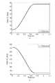
次に、関節105の目標軌道raの設計方法を示す。本実施形態では、目標軌道raは図4に示すような、加速区間−等速区間−減速区間を有する軌道を用いる。ここで、raS,raFはそれぞれ、軌道の初期角度、目標角度である。また、ta,tb,tfinはそれぞれ、等速区間の開始時間、等速区間の終了時間、位置決め終了時間である。本第1実施形態では、加速区間−等速区間−減速区間を有する軌道を用いたが、例えばミニマムジャーク軌道のような等速区間を伴わない軌道であっても構わない。(2.2) Trajectory design Next,a design method of the target trajectory ra of the joint 105 will be described. In the present embodiment, the target trajectory ra is as shown in FIG. 4, acceleration zone - like speed section - used track having a deceleration zone. Here, raS and raF are an initial angle and a target angle of the trajectory, respectively. Further, ta , tb , and tfin are the start time of the constant speed section, the end time of the constant speed section, and the positioning end time, respectively. In the first embodiment, a trajectory having an acceleration section, a constant speed section, and a deceleration section is used. However, a trajectory having no constant speed section, such as a minimum jerk orbit, may be used.
(3)シミュレーション
前節の制御系を用いるシミュレーションを行う。リンクの慣性モーメントをI=8.3×10⁻²kgm2、モーメントアーム径をr=0.1m、弾性、粘性定数をk=25,b=3とする。目標軌道raは、初期角度raS=−20deg、目標角度raF=20deg、等速区間の開始時間ta=0.4秒、等速区間の終了時間tb=0.6秒、位置決め終了時間tfin=1秒とする。関節剛性指令値U1は2.1に示した反復演算アルゴリズムにより、式(9)に示した制約を満たすように導出されている。なお、関節剛性指令の下限値はV1=0.02とし、γ=1として反復演算を行っている。(3) Simulation Perform simulation using the control system in the previous section. The inertia moment of the link is I = 8.3 × 10⁻² kgm2 , the moment arm diameter is r = 0.1 m, the elasticity and the viscosity constant are k = 25, and b = 3. The target trajectory ra has an initial angle raS = −20 deg, a target angle raF = 20 deg, a constant speed section start time ta = 0.4 seconds, a constant speed section end time tb = 0.6 seconds, positioning End time tfin = 1 second. The iterative calculation algorithm shown in joint stiffness command value U1 is 2.1, which is derived to meet the constraint shown in Formula (9). It should be noted that the lower limit value of the joint stiffness command is V1 = 0.02, and γ = 1 is repeated.
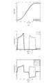
図5(a)に関節の角度θと目標軌道raを、それぞれ実線、破線で、図5(b)に駆動力指令値ue1,uf1の応答をそれぞれ実線、破線で示す。さらに、図5(c)に駆動力指令値ue1,uf1の差を実線で、和を破線で、T1/rの応答を一点鎖線で示す。5 the angle θ and the target trajectoryr a of the joint (a), the solid lines, in dashed lines, respectively the response of the driving force command valueue1, u f1 solid, in broken lines in Figure 5 (b). Further, in FIG. 5C, the difference between the driving force command values ue1 and uf1 is indicated by a solid line, the sum is indicated by a broken line, and the response of T1 / r is indicated by a one-dot chain line.
図5(a)より実線で示す関節105の角度θは、破線で示す軌道raと重なっており、関節105は目標軌道raに追従していることがわかる。図5(b)より、駆動力指令値ue1,uf1はフィードフォワード制御系の制御入力(トルク指令値)T1が式(7)と式(9)に示した条件で配分されているため、人工筋肉の収縮力は正の値のみを取るという特性を満たしていることがわかる。図5(c)において、実線で示すuf1−ue1は、一点鎖線で示すT1/rと重なっており、式(3)の条件を満たしている。また、破線で示すuf1+ue1=U1は、実線で示すT1/rの絶対値に対してV1の間隔をもって近接しており、常に最小値を取っていることがわかる。本第1実施形態の提案手法により、目標軌道raへの追従を実現しながら、最小の駆動力指令値ue1,uf1での拮抗駆動が可能であることがわかる。駆動力指令値ue1,uf1を最小にすることで、例えばMcKibben型人工筋肉では消費する空気の量を最小にすることができる。これにより、タンク等の搭載型の空気源を用いるロボット装置では稼働時間を延長することが可能となる。Angle θ shown in FIG. 5 (a) than indicated by the solid line joints 105, overlaps the trajectory ra indicated by a broken line, the joint 105 is seen to follow the target trajectory ra. From FIG. 5 (b), the driving force command valueue1, u f1 control input of the feed forward control system (torque command value)T 1 is distributed under the conditions shown in equation (9) and equation (7) Therefore, it can be seen that the contraction force of the artificial muscle satisfies the characteristic of taking only a positive value. In FIG. 5C, uf1 −ue1 indicated by the solid line overlaps T1 / r indicated by the alternate long and short dash line and satisfies the condition of the expression (3). Further, it can be seen that uf1 + ue1 = U1 indicated by the broken line is close to the absolute value of T1 / r indicated by the solid line with an interval of V1 and always takes the minimum value. The proposed method of the first embodiment, while realizing the tracking of the target trajectory ra, it can be seen that it is possible to antagonistic driving with minimal driving force command value ue1, uf1. By minimizing the driving force command values ue1 and uf1 , for example, in the McKibben artificial muscle, the amount of air consumed can be minimized. As a result, the operation time can be extended in a robot apparatus using a mounted air source such as a tank.
[第2実施形態]
次に、本発明の第2実施形態に係るロボット装置について説明する。本第2実施形態では、制御部の制御動作が上記第1実施形態の制御部の制御動作と異なるものである。なお、ロボット装置本体の構成について、上記第1実施形態で説明した図1のロボット装置本体の構成と同様の部分については、同一符号を付して詳細な説明を省略する。[Second Embodiment]
Next, a robot apparatus according to a second embodiment of the present invention will be described. In the second embodiment, the control operation of the control unit is different from the control operation of the control unit of the first embodiment. In addition, about the structure of a robot apparatus main body, about the part similar to the structure of the robot apparatus main body of FIG. 1 demonstrated in the said 1st Embodiment, the same code | symbol is attached | subjected and detailed description is abbreviate | omitted.
本第2実施形態では、上記第1実施形態で示したフィードフォワード制御系とフィードバック制御系を併合する2自由度制御系を導出する。フィードバック制御系は、目標軌道と反復演算アルゴリズムで求めた関節剛性指令値に同時に追従可能とするように導出する。フィードフォワード制御系のみでは、リンク101の慣性モーメントなどにパラメータ同定誤差が生ずると制御性能が劣化してしまう。しかし、フィードバック制御系との2自由度制御系を構成することにより、モデル誤差が存在しても目標軌道と関節剛性指令値の同時制御が可能であることを示す。 In the second embodiment, a two-degree-of-freedom control system in which the feedforward control system and the feedback control system shown in the first embodiment are merged is derived. The feedback control system is derived so that it can simultaneously follow the target trajectory and the joint stiffness command value obtained by the iterative calculation algorithm. In the feedforward control system alone, if a parameter identification error occurs in the inertia moment of the
(1)モデリング
本第2実施形態で用いるモデルは上記第1実施形態と同じとする。(1) Modeling The model used in the second embodiment is the same as that in the first embodiment.
(2)制御系設計
フィードフォワード制御系の導出は上記第1実施形態と同様である。本第2実施形態では、上記第1実施形態の反復演算アルゴリズムにより導出される関節トルク指令TFF[m]をTFFと記す。(2) Control system design The feed forward control system is derived in the same manner as in the first embodiment. In the second embodiment, it marks the joint torque command TFF [m] which is derived by iterative calculation algorithm of the first embodiment and TFF.
図6に本第2実施形態に係る制御部150Aのブロック線図である。図6では、図3で示したフィードフォワード制御系の破線で囲まれた部分を、KFFWとして示している。FIG. 6 is a block diagram of a
制御部150Aは、フィードフォワード制御系KFFWの他、更に、補正トルク指令値演算処理154としてのPID制御処理KPID1を実行する機能を有している。The
制御部150Aは、PID制御処理KPID1として、関節105の角度θと目標軌道raとの差分を補償する補正トルク指令値としての制御入力トルクTFBを演算する(補正トルク指令値演算工程)。
ここで、式(2)より、
(uf1−ue1)r=TFF+TFB=T′1 (20)
を満たすようにue1,uf1を決定すれば、関節105にフィードフォワード制御トルクTFFとフィードバック制御トルクTFBの和であるT′1を与えることができる。トルク指令値T′1は、フィードフォワード制御系KFFWのトルク指令値演算処理151(図3参照)で求めたトルク指令値TFFにPID制御処理KPID1で求めた制御入力トルクTFBを加算補正した演算結果である。Here, from equation (2),
(Uf1 −ue1 ) r = TFF + TFB = T ′1 (20)
If ue1 and uf1 are determined so as to satisfy the condition, T ′1 which is the sum of the feedforward control torqueTFF and the feedback control torqueTFB can be given to the joint 105. The torque command value T ′1 is obtained by adding the control input torque TFB obtained by the PID control process KPID1 to the torque command value TFF obtained by the torque command value calculation process 151 (see FIG. 3) of the feedforward control system KFFW . This is a corrected calculation result.
したがって、本第2実施形態では、駆動力指令値演算処理155を実行する際に、各駆動力指令値の算出に用いるトルク指令値として、トルク指令値T′1を用いる。Therefore, in the second embodiment, when the driving force command
ところで、上記第1実施形態と同様に、同時に関節105の剛性に関する条件
U1=uf1+ue1=U1[m] (21)
を満たすように、駆動力指令値ue1,uf1を決定する必要がある。By the way, as in the first embodiment, the condition regarding the stiffness of the joint 105 is simultaneously U1 = uf1 + ue1 = U1 [m] (21)
It is necessary to determine the driving force command values ue1 and uf1 so as to satisfy the above.
トルク指令値T′1と関節剛性指令値U1を同時に満たすには、式(20)と式(4)を駆動力指令値ue1,uf1について解き、In order to satisfy the torque command value T ′1 and the joint stiffness command value U1 at the same time, the equations (20) and (4) are solved for the driving force command values ue1 and uf1 .
−U1r<T′1<U1r (23)
という条件を満たす必要がある。これにより、関節105の剛性が関節剛性指令値U1となると同時に、トルク指令値T′1により目標軌道raに追従制御される。式(23)を実現するには、制御部150Aは、図6のブロック線図に示すように、
|T′1|<U1r (24)
と制御入力を制約する制約処理156を実行すればよい。もしくは、PID制御処理KPID1のゲインを変動させ、式(23)の範囲に制御入力の大きさを収めるなどの方法がある。
-U 1 r <T '1 < U 1 r (23)
It is necessary to satisfy the condition. Thus, the rigidity of the joint 105 at the same time the joint stiffness command value U1, is controlled to follow the target trajectory ra by the torque command value T'1. In order to realize Equation (23), the
| T ′1 | <U1 r (24)
The
上記第1実施形態において、剛性下限値V1を設定することにより、関節剛性を制御することが可能であることを示した。しかし、フィードバック制御系のゲインが高い場合には、それによる関節105の剛性が支配的になってしまう。In the first embodiment, by setting the stiffness lower limit V1, showed that it is possible to control the joint stiffness. However, when the gain of the feedback control system is high, the rigidity of the joint 105 is dominant.
そこで、制御部150Aは、図6に示すように、接触ゲインGtを導入し、接触が発生した場合は、Gt=0とすることでフィードバック系を遮断する。これにより、手先が人や物に接触したことを検知するなどの任意の時刻で、速やかにリンク101の剛性を関節剛性指令値U1へと切り替えることができる。Therefore, as shown in FIG. 6, the
本第2実施形態では、PID制御処理KPID1に用いる伝達関数を、In the second embodiment, the transfer function used for the PID control process KPID1 is
(3)シミュレーション
前節で導出した制御系を用いてシミュレーションを行った。リンク101のパラメータと目標軌道raは上記第1実施形態と同様とする。本第2実施形態では、モデルの同定誤差に対する制御性能の検証を行うため、リンク101の慣性モーメントをI′=1.05Iとし、フィードフォワード制御入力生成時のモデルに対して誤差を有するモデルを用いてシミュレーションを行った。また本第2実施形態では、上記第1実施形態のように関節剛性指令の下限値を小さくすると、フィードバック制御系の制約の範囲が小さくなることで、ワインドアップ現象を発生しやすくなってしまう。そこで、V1=0.1としてフィードフォワード入力を導出している。(3) Simulation A simulation was performed using the control system derived in the previous section. Parameters and target trajectory ra link 101 similar to the first embodiment. In the second embodiment, in order to verify the control performance with respect to the identification error of the model, the inertia moment of the
図7(a)に関節105の角度θと目標軌道raを、それぞれ実線、破線で、図7(b)に駆動力指令値ue1,uf1の応答をそれぞれ実線、破線で示す。さらに、図7(c)に駆動力指令値ue1,uf1の差を実線で、和を破線で、T′1/rの応答を一点鎖線で示す。また、図7(d)にTFF,TFBをそれぞれ実線、破線で示す。The angle θ and the target trajectoryr a of the joint 105 in FIG. 7 (a), solid lines, in dashed lines, respectively the response of the driving force command valueue1, u f1 solid, by the broken line in FIG. 7 (b). Further, in FIG. 7C, the difference between the driving force command values ue1 and uf1 is indicated by a solid line, the sum is indicated by a broken line, and the response of T ′1 / r is indicated by a one-dot chain line. FIG. 7D shows TFF and TFB with a solid line and a broken line, respectively.
図7(a)より、実線で示す関節105の角度θは破線で示す目標軌道raと重なっており、関節105は目標軌道raに追従していることがわかる。フィードフォワード制御系のみでは、モデル誤差により軌道に追従することはできない。しかし、図7(d)の破線で示すように、フィードバック制御入力がモデル誤差を補償しているため、追従することを可能としている。図7(b)より、駆動力指令値ue1,uf1は2自由度制御系の制御入力T′1が、式(22)と式(24)に示した条件で配分されているため、人工筋肉の収縮力は正の値のみを取るという特性を満たしていることがわかる。図7(c)において、実線で示すuf1−ue1は、一点鎖線で示すT′1/rと重なっており、式(20)の条件を満たしている。また、破線で示すuf1+ue1=U1は、上記第1実施形態と同様に、実線で示すT′1/rの絶対値に近接しており、式(24)の制約を満たす範囲で、常に最小値を取っていることがわかる。本第2実施形態で示した2自由度制御系により、モデルに同定誤差などが存在しても、目標軌道raへの追従を実現しながら、最小の収縮力での拮抗駆動が可能であることがわかる。7 (a), the angle θ of the joint 105 shown by the solid line overlaps the target trajectory ra indicated by a broken line, the joint 105 is seen to follow the target trajectory ra. The feedforward control system alone cannot follow the trajectory due to model errors. However, as indicated by the broken line in FIG. 7D, the feedback control input compensates for the model error, so that it is possible to follow. As shown in FIG. 7B, the driving force command values ue1 and uf1 are allocated to the control input T ′1 of the two-degree-of-freedom control system under the conditions shown in the equations (22) and (24). It can be seen that the contraction force of the artificial muscle satisfies the characteristic of taking only a positive value. In FIG. 7C, uf1 -ue1 indicated by the solid line overlaps T ′1 / r indicated by the alternate long and short dash line, which satisfies the condition of Expression (20). Also, uf1 + ue1 = U1 indicated by a broken line is close to the absolute value of T ′1 / r indicated by a solid line, as in the first embodiment, and is within a range satisfying the constraint of Expression (24). It can be seen that the minimum value is always taken. The 2-degree-of-freedom control system shown in the second embodiment, also including identification error in the model exists, while realizing the tracking of the target trajectory ra, it is possible antagonistic driving with minimal contraction force I understand that.
[第3実施形態]
次に、本発明の第3実施形態に係るロボット装置について詳細に説明する。図8は、本発明の第3実施形態に係るロボット装置の概略構成を示す説明図である。本第3実施形態では、人工筋肉アクチュエータを用いた3対6筋を有する2リンクマニピュレータとしてのロボット装置200の手先剛性の制御を例として説明する。[Third Embodiment]
Next, a robot apparatus according to a third embodiment of the present invention will be described in detail. FIG. 8 is an explanatory diagram showing a schematic configuration of the robot apparatus according to the third embodiment of the present invention. In the third embodiment, the control of the hand rigidity of the
(1)モデリング
図8に示すロボット装置200は、プーリ203と、プーリ203に対して旋回可能に第1関節211を介して連結された第1リンク201と、第1リンク201に対して旋回可能に第2関節212を介して連結された第2リンク202とを備えている。(1) Modeling The
第1リンク201は、長手部材からなり、その基端201aがプーリ203にx−y直交座標系の平面(以下、「作業平面」という)内で旋回可能に支持されている。第2リンク202は、長手部材からなり、その基端202aが第1リンク201の先端201bに作業平面内で旋回可能に支持されている。 The
第2リンク202の先端(以下、「リンク先端」という)202bには、不図示のエンドエフェクタ(例えばハンド)が設けられている。つまり、第1リンク201は、第1関節211と第2関節212との間に配置され、第1関節211で旋回可能に支持されており、第2リンク202は、第2関節212で旋回可能に支持されている。 An end effector (for example, a hand) (not shown) is provided at the tip (hereinafter referred to as “link tip”) 202 b of the
なお、本第2実施形態では、第1リンク201に対しては、プーリ203が基体となり、第2リンク202に対しては、第1リンク201が基体となる。このプーリ203は、例えばロボット胴体等に設けられている。 In the second embodiment, the
ロボット装置200は、一対の第1アクチュエータe1,f1と、一対の第2アクチュエータe2,f2と、一対の第3アクチュエータe3,f3と、を備えている。各第1アクチュエータe1,f1は、一端がプーリ203に接続され、他端が第1リンク201の長手方向中央部に接続され、駆動力の差により第1リンク201を旋回させるように拮抗配置されている。The
また、各第2アクチュエータe2,f2は、一端が第1リンク201の長手方向中央部に接続され、他端が第2リンク202の基端202aに接続され、駆動力の差により第2リンク202を旋回させるように拮抗配置されている。また、各第3アクチュエータe3,f3は、一端がプーリ203に接続され、他端が第2リンク202の基端202aに接続され、駆動力の差により第1リンク201及び第2リンク202を旋回させるように拮抗配置されている。つまり、第1アクチュエータe1,f1は、第1リンク201を挟んで第1リンク201の両側に対称配置されている。また、第2アクチュエータe2,f2は、第1リンク201を挟んで第1リンク201の両側に対称配置されている。また、第3アクチュエータe3,f3は、第1リンク201を挟んで第1リンク201の両側に対称配置されている。Each of the second actuators e2 and f2 has one end connected to the longitudinal center of the
また、ロボット装置200は、各アクチュエータe1,f1,e2,f2,e3,f3の駆動力を各駆動力指令値により設定して、リンク201,202の動作を制御する制御部250を備えている。Further, the
第1アクチュエータe1,f1は、第1リンク201を駆動する第1の一関節駆動アクチュエータである。第2アクチュエータe2,f2は、第2リンク202を駆動する第2の一関節駆動アクチュエータである。また、第3アクチュエータe3,f3は、第1リンク201と第2リンク202を同時に駆動する二関節同時駆動アクチュエータである。人の上腕部や下肢大腿部には、二関節筋とよばれる二関節同時駆動アクチュエータが存在することが知られている。人の四肢の筋配列は複雑だが、実効筋概念が導入され、3対6筋を有する2リンクモデルが提示されている。The first actuators e1 and f1 are first joint driving actuators that drive the
各アクチュエータe1,f1,e2,f2,e3,f3は、図1に示す筋の粘弾性特性を有する人工筋肉アクチュエータである。人工筋肉アクチュエータは、筋の粘弾性と呼ばれる特性と類似する特性を有するアクチュエータである。筋は図1に示すように、力発生要素と弾性要素と粘性要素を用いてモデル化される。The actuators e1 , f1 , e2 , f2 , e3 , and f3 are artificial muscle actuators having the muscle viscoelastic characteristics shown in FIG. The artificial muscle actuator is an actuator having a characteristic similar to a characteristic called muscle viscoelasticity. As shown in FIG. 1, the muscle is modeled using a force generating element, an elastic element, and a viscous element.
図8のアクチュエータe1,f1,e2,f2,e3,f3について、uen,ufn(n=1,2,3)を力発生要素の駆動力を発生させる駆動力指令値とする。また、ken,kfn,ben,bfn(n=1,2,3)を人工筋肉アクチュエータの弾性力定数、粘性力定数とする。第1,第2リンク201,202の角度、つまり関節の角度をθ1,θ2、第1,第2リンク201,202の慣性モーメントをI1,I2、第1,第2リンク201,202の長さを2×l1,2×l2、第1,第2リンク201,202の質量をm1,m2とする。For the actuators e1 , f1 , e2 , f2 , e3 , and f3 in FIG. 8, uen and ufn (n = 1, 2, 3) are used to generate a driving force command for generating the driving force of the force generating element Value. Further, ken , kfn , ben , and bfn (n = 1, 2, 3) are set as the elastic force constant and the viscous force constant of the artificial muscle actuator. The angles of the first and
モーメントアーム径、つまり第1リンク201の旋回中心点とプーリ203におけるアクチュエータe1,f1の接続点との長さ、及び第2リンク202の旋回中心点と第2リンク202におけるアクチュエータe2,f2の接続点との長さをrとする。The moment arm diameter, that is, the length of the turning center point of the
本第3実施形態では、各筋の弾性力定数,粘性力定数をいずれもk,bとすると、運動方程式は、以下の式(26)及び式(27)となる。 In the third embodiment, when the elastic force constant and the viscous force constant of each muscle are both k and b, the equations of motion are the following equations (26) and (27).
(2)制御系設計
上記第1及び第2実施形態では、収縮力(駆動力)を最小にする関節の軌道制御を行ったが、本第3実施形態においても、2自由度制御系を設計する。(2) Control system design In the first and second embodiments, the trajectory control of the joint that minimizes the contraction force (driving force) is performed. In the third embodiment, a two-degree-of-freedom control system is also designed. To do.
図9に本第3実施形態の制御部250のブロック線図を示す。また、図10に、フィードフォワード制御のブロック線図を示す。KFFWで示すブロックがフィードフォワード制御系である。制御部250は、トルク指令値演算処理251、変更演算処理252、反復処理253、補正トルク指令値演算処理254及び駆動力指令値演算処理255を実行する。本第3実施形態では、制御部250は、関節211,212の角度を目標軌道に追従させるのに必要な各アクチュエータen,fnの各駆動力指令値uen,ufnを求める。そして、制御部250は、各アクチュエータen,fnに発生させる駆動力が駆動力指令値uen,ufnとなるように、各アクチュエータen,fnを制御する。FIG. 9 shows a block diagram of the
(2.1)フィードフォワード制御系
上記第1実施形態と同様に、駆動力指令値の差をTn、和をUnとおくと、
(ufn−uen)r=TFFn+TFBn=Tn,n=1,2,3 (28)
ufn+uen=Un,n=1,2,3 (29)
と表せる。ここで、TFFn,TFBnは、それぞれフィードフォワード制御系、フィードバック制御系により与えられるトルク指令値である。本節では、TFBn=0としてフィードフォワード制御入力の導出方法を示す。(2.1) like the feed-forward control system in the first embodiment, the difference of Tn of the driving force commandvalue, placing the sum and Un,
(Ufn −uen ) r = TFFn + TFBn = Tn , n = 1, 2, 3 (28)
ufn + uen = Un , n = 1, 2, 3 (29)
It can be expressed. Here, TFFn and TFBn are torque command values given by the feedforward control system and the feedback control system, respectively. In this section, a method for deriving the feedforward control input is shown with TFBn = 0.
式(26)及び式(27)をθv=[θ1 θ2]T,Tv=[T1+T3 T2+T3]Tと定義して行列表記すると、When Expression (26) and Expression (27) are defined as θv = [θ1 θ2 ]T , Tv = [T1 + T3 T2 + T3 ]T and expressed in matrix,
θcv=[θc1 θc2]T (32)
となる。関節角度θn(n=1,2)に対する目標軌道をran(n=1,2)とし、
rav=[ra1 ra2]T (33)
と定義する。目標軌道の角速度、角加速度をそれぞれ、
θcv = [θc1 θc2 ]T (32)
It becomes. The target trajectory for the joint angle θn (n = 1, 2) is ran (n = 1, 2),
rav = [ra1 ra2 ]T (33)
It is defined as The angular velocity and acceleration of the target trajectory are
しかし、二関節同時駆動アクチュエータを有するマニピュレータは、制御される自由度に対して、制御入力の数が冗長である。そのため、逆動力学により各関節211,212に対するトルク指令値(以下、各関節トルクと略す)は求められるが、二関節駆動アクチュエータによるトルクを含む指令TFFn(n=1,2,3)を一意に決定できない。そこで、式(34)右辺から得られる関節トルク指令をTMF=[TMF1 TMF2]Tとおき、TFFn(n=1,2,3)の絶対値の最大値
max(|TFFn|,n=1,2,3) (35)
が最小となるように、各関節トルク指令TMFを分配する。However, a manipulator having a two-joint simultaneous drive actuator has a redundant number of control inputs for the degree of freedom to be controlled. For this reason, torque command values (hereinafter abbreviated as “joint torques”) for the
Each joint torque commandTMF is distributed so that is minimized.
まず、TMFとTFFn(n=1,2,3)の関係は、式(36)及び式(37)となる。
TFF1+TFF3=TMF1 (36)
TFF2+TFF3=TMF2 (37)First, the relationship ofT MF andT FFn (n = 1, 2, 3) is a formula (36) and (37).
TFF1 + TFF3 = TMF1 (36)
TFF2 + TFF3 = TMF2 (37)
TMF1,TMF2が同符号の場合、式(36)及び式(37)より、TFF3を増減させるとTFF3の変化量だけTFF1とTFF2を増減できることがわかる。TMF1≦TMF2である場合、TFF3を0から徐々に増減させ、TFF1=TFF3とすればよい。このとき、TFFn(n=1,2,3)は、それぞれ、If TMF1,T MF2 is the same sign, formula (36) and the equation(37), it can be seen that decreasing the amount of change byT FF1 andT FF2 of the increase or decrease theT FF3T FF3. When TMF1 ≦ TMF2 , TFF3 may be gradually increased or decreased from 0 so that TFF1 = TFF3 . At this time, TFFn (n = 1, 2, 3) is respectively
TMF1,TMF2が異符号の場合は、例えばTFF3の増加によりTFF1の絶対値は減少するがTFF2の絶対値は増加してしまう。従って、TFF1,TFF2を、
|TFF1|=|TFF2| (40)
とすればよい。また、TMF1とTMF2が異符号で、式(40)を満たす場合、TFF1とTFF2は異符号となるため、式(36)、式(37)及び式(40)より、When TMF1 and TMF2 have different signs, for example, an increase in TFF3 decreases the absolute value of TFF1 , but increases the absolute value of TFF2 . Therefore, TFF1 and TFF2 are
| TFF1 | = | TFF2 | (40)
And it is sufficient. In addition, when TMF1 and TMF2 have different signs and satisfy Expression (40), TFF1 and TFF2 have different signs. Therefore, from Expression (36), Expression (37), and Expression (40),
これを用いて、上記第1実施形態と同様に、収縮方向のみに力を発生するという条件、
|TFFn|<Unr,n=1,2,3 (42)
を成立するトルク指令値TFFnと関節剛性指令値Unとを反復演算アルゴリズムにより求める。Using this, as in the first embodiment, the condition that force is generated only in the contraction direction,
| TFFn | <Un r, n = 1,2,3 (42)
Torque command value TFFn and joint stiffness command value Unsatisfying are obtained by an iterative calculation algorithm.
本第3実施形態では、上記第1実施形態と同様に、反復回数をiとして、i回の反復演算による、トルク指令値TFFnと関節剛性指令値Unを
TFFn[i],Un[i],n=1,2,3 (43)
と表記する。また、Un[i]が要素に含まれる筋の粘弾性による剛性行列、減衰行列をKv[i],Cv[i]と表記する。In the third embodiment, similarly to the first embodiment, the number of iterations as i, by i iterations operation, the TFFn torque command valueT FFn and joint stiffness command valueU n[i],U n[I] , n = 1, 2, 3 (43)
Is written. In addition, Un [i] is expressed as Kv [i] , Cv [i] as a stiffness matrix and a damping matrix due to viscoelasticity of muscles included in the element.
制御部250は、トルク指令値演算処理251として、リンク201,202の逆動力学により、目標軌道、目標軌道の角速度、目標軌道の角加速度、関節剛性指令値を用いて、関節211,212に必要なトルクを示すトルク指令値TFFn[i]を演算する。
つまり、制御部250は、式(44)に基づき、i回目の反復によるトルク指令値TFFn[i]を演算する(トルク指令値演算工程)。As the torque command
That is, the
ここで、制御部250は、式(44)を、式(38)〜(41)に示した方法により分配しTFFn[i](n=1,2,3)を求める。Here, the
次に、制御部250は、変更演算処理252として、関節剛性指令値Un[i]と、トルク指令値TFFn[i]の絶対値をリンクのモーメントアーム径rで割った値|TFFn[i]|/rとの差分を演算する。この差分をEn[i]とすると、制御部250は、以下の式(45)により差分E1[i]を演算する。Next, the
なお、本第3実施形態では、関節剛性指令値Unに対する剛性下限値をVnとし、式(42)の条件に対する差分En[i]を以下のように定義している。
En[i]=Un[i]−|TFFn[i]|/r−Vn,n=1,2,3 (45)Incidentally, in the third embodiment, the rigidity limit value for the joint stiffness command value Un and Vn, are defined as follows difference En [i] for the condition of formula (42).
E n [i] = U n [i] - | T FFn [i] | / r-V n, n = 1,2,3 (45)
次に、制御部250は、変更演算処理252として、関節剛性指令値Un[i]から、差分En[i]に0よりも大きく1以下の収束係数γを乗じた値を引く演算を行うことで、関節剛性指令値Un[i]を変更する(変更演算工程)。つまり、制御部250は、反復演算アルゴリズムの収束係数γを0<γ≦1として、i+1回目の関節剛性指令値Un[i+1]を以下の式(46)により求める。
Un[i+1]=Un[i]−γEn[i],n=1,2,3 (46)Next, the
Un [i + 1] = Un [i] −γEn [i] , n = 1, 2, 3 (46)
制御部250は、反復処理253として、式(44)〜式(46)の演算を、差分En[i]が所定値以下(例えば0)に収束するまで所定回数m、反復して行う(反復工程)。As the
図10に示すDistribution Algorithmのブロックでは、式(38)〜(41)に示した分配アルゴリズムを実行し、Iteration Algorithmのブロックでは、式(44)〜式(46)の反復演算アルゴリズムを実行する。 In the distribution algorithm block shown in FIG. 10, the distribution algorithm shown in equations (38) to (41) is executed, and in the iteration algorithm block, the iterative operation algorithm shown in equations (44) to (46) is executed.
次に、フィードフォワード制御のみを行う場合(つまりTFBn=0の場合)についての駆動力指令値演算処理255(図9)について説明する。なお、トルク指令値はTn=TFFWnである。Next, the driving force command value calculation process 255 (FIG. 9) when only feedforward control is performed (that is, when TFBn = 0) will be described. The torque command value is Tn = TFFWn .
制御部250は、反復処理253の終了後、駆動力指令値演算処理255として、関節剛性指令値Un[m]及びトルク指令値Tn[m]を用いて、各駆動力指令値を演算する各駆動力指令値uen,ufnを演算する(駆動力指令値演算工程)。これにより、関節211,212にはトルク指令値Tnに対応するトルクが印加され、関節211,212の角度θ1,θ2が目標軌道に追従する。The
(2.2)2自由度制御系
フィードフォワード制御と共にフィードバック制御も行う場合は、制御部250は、図9に示す、補正トルク指令値演算処理254として、PID制御処理KPID1〜KPID3を実行する(補正トルク指令値演算工程)。(2.2) Two-degree-of-freedom control system When performing feedback control together with feedforward control, the
そして、制御部250は、トルク指令値Tnとして、フィードフォワード入力TFFnに制御入力トルクTFBnを加算補正した結果を用いる。その際、制御部250は、上記第2実施形態と同様、制約処理256として式(30)で制約し、収縮力ufn,uenを求める。Then, the
以下、具体的に説明すると、図9に示すフィードバック制御系であるPID制御処理KPID1,KPID2では、関節角度θ1,θ2と目標軌道ra1,ra2との差分を補償するための制御入力トルクTFB1,TFB2を演算する。さらに、PID制御処理KPID3では、関節角度θ1+θ2と目標角度ra1+ra2との差分を補償するための制御入力トルクTFB3を演算する。Specifically, in the PID control processes KPID1 and KPID2 which are feedback control systems shown in FIG. 9, the difference between the joint angles θ1 and θ2 and the target trajectories ra1 and ra2 is compensated. Control input torques TFB1 and TFB2 are calculated. Further, in the PID control process KPID3 , a control input torque TFB3 for compensating for the difference between the joint angle θ1 + θ2 and the target angle ra1 + ra2 is calculated.
そして、制御入力Tn(n=1,2,3)に対して上記第2実施形態と同様に、
|Tn|<Unr,n=1,2,3 (47)
と制約する。駆動力指令値ufn,uen(n=1,2,3)は、And, similarly to the second embodiment, the control input Tn (n = 1, 2, 3)
| Tn | <Un r, n = 1,2,3 (47)
And constrain. The driving force command values ufn and uen (n = 1, 2, 3) are
(2.3)手先剛性制御
2リンクマニピュレータでは、手先が外界と直に接触するので、手先の剛性を制御することが重要である。手先の剛性は、図11に示すようなスティフネス楕円によって表される。この楕円は、各方向に対しての剛性の分布を示し、手先と楕円の距離が離れるほど剛性が高いことを表している。上記第1実施形態の1リンクマニュピレータでは、関節の剛性と手先の剛性は同一であった。本第3実施形態の3対6筋を有する2リンクマニュピレータでは、関節剛性指令値U1,U2,U3を制御することにより手先の剛性が求まる。例えば、関節剛性指令値U1,U2,U3を
U1=U2=U3 (49)
と制御すると、スティフネス楕円の長軸は第1関節と手先を結ぶ方向を向くことが知られている。本第3実施形態では、剛性は収縮力が最小値となるように反復演算されるため、駆動中の剛性を任意に指定することはできない。しかし、手先の目標位置で手先剛性を制御することは可能である。本第3実施形態では、図12に示すように、関節剛性指令値の下限値を可変させ、手先の目標位置で、式(49)を満たすように剛性の制御を行う。(2.3) Hand rigidity control In the two-link manipulator, the hand is in direct contact with the outside world, so it is important to control the rigidity of the hand. The rigidity of the hand is represented by a stiffness ellipse as shown in FIG. This ellipse indicates the distribution of rigidity in each direction, and indicates that the rigidity increases as the distance between the hand and the ellipse increases. In the one-link manipulator of the first embodiment, the joint rigidity and the hand rigidity are the same. In the two-link manipulator having 3 to 6 muscles of the third embodiment, the stiffness of the hand is obtained by controlling the joint stiffness command values U1 , U2 , U3 . For example, the joint stiffness command values U1 , U2 , U3 are set to U1 = U2 = U3 (49)
It is known that the long axis of the stiffness ellipse faces the direction connecting the first joint and the hand. In the third embodiment, since the rigidity is repeatedly calculated so that the contraction force becomes the minimum value, the rigidity during driving cannot be arbitrarily designated. However, it is possible to control the hand stiffness at the target position of the hand. In the third embodiment, as shown in FIG. 12, the lower limit value of the joint stiffness command value is varied, and the stiffness is controlled so as to satisfy Expression (49) at the target position of the hand.
(2.4)軌道設計
本第3実施形態では、目標軌道を手先が図8のy軸上を正方向に駆動するように設定する。さらに上記第1実施形態と同様に加速区間−等速区間−減速区間を有するものとする。関節角度に対する目標軌道ra1,ra2は、手先軌道から逆運動学により求める。本第3実施形態では、加速区間−等速区間−減速区間を有する軌道を用いたが、例えばミニマムジャーク軌道のような等速区間を伴わない軌道であっても構わない。(2.4) Trajectory Design In the third embodiment, the target trajectory is set so that the hand drives in the positive direction on the y-axis in FIG. Further, similarly to the first embodiment, it is assumed that there are an acceleration section, a constant speed section, and a deceleration section. The target trajectories ra1 and ra2 with respect to the joint angle are obtained from the hand trajectory by inverse kinematics. In the third embodiment, a trajectory having an acceleration section, a constant speed section, and a deceleration section is used. However, a trajectory without a constant speed section such as a minimum jerk trajectory may be used.
(3)シミュレーション
前節の制御系を用いたシミュレーションを行う。第1リンク201と第2リンク202の物理パラメータは同一とする。リンク長さを0.2m、リンクの慣性モーメントをI1=I2=1.3×10⁻³kgm2、モーメントアーム径を0.05m、弾性、粘性定数をk=12,b=0.003とする。目標軌道は、等速区間の開始時間ta=0.2747秒、等速区間の終了時間tb=0.4746秒、位置決め終了時間tfin=0.75秒とする。また、関節トルクが作用しないときの弾性力による中立姿勢角度θc1,θc2は、手先軌道の中間地点における関節角度とし、θc1=29.7deg、θc2=120.7degとする。さらに、本第1実施形態では、上記第2実施形態と同様に、2自由度制御系のモデルの同定誤差に対する検証を行う。そのため、フィードフォワード入力の生成では慣性モーメントをI1,I2とするが、シミュレーションではリンクの慣性モーメントをI1′=1.1I1,I2′=1.05I2とする。(3) Simulation Perform simulation using the control system in the previous section. The physical parameters of the
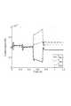
図13(a)及び図13(b)に第1、第2リンクの関節角度θ1,θ2を実線で、目標軌道ra1,ra2を破線で示す。図14(a)〜図14(c)に駆動力指令値uf1,uf2,uf3の応答を実線で、駆動力指令値ue1,ue2,ue3の応答を破線で示す。さらに、図15(a)〜図15(c)に駆動力指令値uen,ufn(n=1,2,3)の差を実線で、和を破線で、Tn/r(n=1,2,3)の応答を一点鎖線で示す。また、図16にTFB1,TFB2,TFB3をそれぞれ実線、破線、一点鎖線で示す。13A and 13B, the joint angles θ1 and θ2 of the first and second links are indicated by solid lines, and the target trajectories ra1 and ra2 are indicated by brokenlines . 14A to 14C, the responses of the driving force command values uf1 , uf2 and uf3 are shown by solidlines , and the responses of the driving force command values ue1 , ue2 and ue3 are shown by brokenlines . Further, in FIGS. 15A to 15C, the difference between the driving force command values uen , ufn (n = 1, 2, 3) is indicated by a solid line, the sum is indicated by a broken line, and Tn / r (n = The response of 1, 2, 3) is indicated by a dashed line. FIG. 16 shows TFB1 , TFB2 , and TFB3 by a solid line, a broken line, and a one-dot chain line, respectively.
図13(a)及び図13(b)より実線で示す関節角度は破線で示す軌道と重なっており、リンクは目標軌道に追従していることがわかる。上記第2実施形態と同様、図16に示すように、フィードバック制御入力がモデル誤差を補償しているためである。図14(a)より、駆動力指令値ue1,uf1は2自由度制御系の制御入力T1を、式(47)と式(48)に示した条件で配分されているため、人工筋肉の収縮力は正の値を取るという特性を満たしていることがわかる。図14(b)及び図14(c)より、駆動力指令値ue2,uf2,ue3,uf3も同様に正の値を取っていることがわかる。From FIG. 13 (a) and FIG. 13 (b), it can be seen that the joint angle indicated by the solid line overlaps the trajectory indicated by the broken line, and the link follows the target trajectory. This is because the feedback control input compensates for the model error as shown in FIG. 16 as in the second embodiment. As shown in FIG. 14A, since the driving force command values ue1 and uf1 are allocated to the control input T1 of the two-degree-of-freedom control system under the conditions shown in the equations (47) and (48), It can be seen that the contraction force of the muscle satisfies the characteristic of taking a positive value. From FIG. 14B and FIG. 14C, it can be seen that the driving force command values ue2 , uf2 , ue3 and uf3 are also positive values.
図15(a)において、実線で示すuf1−ue1は、一点鎖線で示すT1/rと重なっており、式(28)の条件を満たしている。同様に、図15(b)及び図15(c)において、実線で示すU2,U3は、一点鎖線で示すT2/r,T3/rと重なっている。また図15(a)〜図15(c)において、破線で示すuf1+ue1=U1,uf2+ue2=U2,uf3+ue3=U3は、図12に設定した0〜0.625秒のVn(n=1,2,3)が0に近い区間では、実線で示すT′1/rの絶対値に近接している。これから、上記第1及び第2実施形態と同様に、式(47)の制約を満たす範囲で、常に最小値を取っていることがわかる。さらに、Vnが増加する0.65秒以降では、各拮抗対の剛性はT′1/r(n=1,2,3)の絶対値に対して大きな値へと移行している。これより、手先のスティフネス楕円は目標軌道において、式(49)の条件を満たすように制御されていることがわかる。本第3実施形態の提案手法により、モデルに同定誤差などが存在する場合でも、最小の収縮力で目標軌道への追従を実現しながら、目標位置では3対6筋の弾性により手先の剛性を制御することが可能であることがわかる。In FIG. 15A, uf1 −ue1 indicated by the solid line overlaps T1 / r indicated by the alternate long and short dash line, and satisfies the condition of Expression (28). Similarly, in FIGS. 15B and 15C, U2 and U3 indicated by solid lines overlap with T2 / r and T3 / r indicated by alternate long and short dash lines. 15A to 15C, uf1 + ue1 = U1 , uf2 + ue2 = U2 , and uf3 + ue3 = U3 indicated by broken lines are 0 to 0 set in FIG. In a section where Vn (n = 1, 2, 3) of .625 seconds is close to 0, it is close to the absolute value of T ′1 / r indicated by a solid line. From this, it can be seen that, as in the first and second embodiments, the minimum value is always taken within the range satisfying the constraint of Expression (47). Furthermore, after 0.65 seconds when Vn increases, the stiffness of each antagonistic pair shifts to a large value with respect to the absolute value of T ′1 / r (n = 1, 2, 3). From this, it can be seen that the stiffness ellipse of the hand is controlled so as to satisfy the condition of Expression (49) in the target trajectory. With the proposed method of the third embodiment, even if there is an identification error or the like in the model, the rigidity of the hand is improved by the elasticity of 3 to 6 muscles at the target position, while following the target trajectory with the minimum contraction force. It can be seen that it can be controlled.
なお、本発明は、以上説明した実施形態に限定されるものではなく、多くの変形が本発明の技術的思想内で当分野において通常の知識を有する者により可能である。 The present invention is not limited to the embodiments described above, and many modifications can be made by those having ordinary knowledge in the art within the technical idea of the present invention.
100…ロボット装置、101…リンク、105…関節、150…制御部、151…トルク指令値演算処理、152…変更演算処理、153…反復処理、155…駆動力指令値演算処理DESCRIPTION OF
Claims (12)
Translated fromJapanese前記リンクの逆動力学により、前記目標軌道、前記目標軌道の角速度、前記目標軌道の角加速度、前記各駆動力指令値の合計値を示す関節剛性指令値を用いて、前記関節に必要なトルクを示すトルク指令値を演算するトルク指令値演算工程と、
前記関節剛性指令値と、前記トルク指令値の絶対値を前記リンクのモーメントアーム径で割った値との差分を演算し、前記関節剛性指令値から、前記差分に0よりも大きく1以下の係数を乗じた値を引く演算を行うことで、前記関節剛性指令値を変更する変更演算工程と、
前記差分が所定値以下に収束するまで、前記トルク指令値演算工程及び前記変更演算工程の演算を反復して行う反復工程と、
前記差分が所定値以下に収束した場合、前記関節剛性指令値及び前記トルク指令値を用いて、前記各駆動力指令値を演算する駆動力指令値演算工程と、を備えたことを特徴とするロボット装置の制御方法。A link that is pivotably connected to the base via a joint and a driving force that pulls the link in a direction opposite to each other with respect to the base are generated, and torque is applied to the joint due to a difference in the driving force and driving. comprising a pair of actuators for imparting rigidity to the joint by the sum of forces, thefront Symbol seeking the driving force command values for the actuators, the driving force to be generated to the each actuator is the respective driving force command value As described above, in the control method of the robot apparatus that controls the respective actuators so thatthe joint angle of the joint follows the target trajectory ,
Torque required for the joint by using the joint stiffness command value indicating the total value of the target trajectory, the angular velocity of the target trajectory, the angular acceleration of the target trajectory, and the driving force command values by the reverse dynamics of the link A torque command value calculating step for calculating a torque command value indicating
A difference between the joint stiffness command value and a value obtained by dividing the absolute value of the torque command value by the moment arm diameter of the link is calculated, and from the joint stiffness command value, the difference is a coefficient greater than 0 and less than or equal to 1 A change calculation step of changing the joint stiffness command value by subtracting the value multiplied by
An iterative process of repeatedly performing the torque command value calculating step and the change calculating step until the difference converges to a predetermined value or less;
A driving force command value calculating step of calculating each driving force command value using the joint stiffness command value and the torque command value when the difference converges to a predetermined value or less. A method for controlling a robotic device.
前記駆動力指令値演算工程では、前記各駆動力指令値の演算に用いる前記トルク指令値として、前記トルク指令値演算工程で求めた前記トルク指令値に前記補正トルク指令値演算工程で求めた前記補正トルク指令値を加算補正した結果を用いることを特徴とする請求項1に記載のロボット装置の制御方法。A correction torque command value calculation step for calculating a correction torque command value for compensating for a difference between the angle of the joint and the target trajectory;
In the driving force command value calculating step, the torque command value used in the calculation of each driving force command value is calculated as the torque command value determined in the torque command value calculating step in the corrected torque command value calculating step. The robot apparatus control method according to claim 1, wherein a result obtained by adding and correcting the corrected torque command value is used.
前記関節が第1関節であり、 The joint is a first joint;
前記ロボット装置が、前記第1リンクに対して第2関節を介して旋回可能に連結された第2リンクを更に有していることを特徴とする請求項1乃至4のいずれか1項に記載のロボット装置の制御方法。 5. The robot apparatus according to claim 1, wherein the robot apparatus further includes a second link connected to the first link via a second joint so as to be able to turn. Method for controlling a robotic device.
前記第1リンクと前記第2リンクとを同時に互いに反対方向に駆動する一対の二関節駆動型のアクチュエータと、を更に有することを特徴とする請求項5に記載のロボット装置の制御方法。 The robot apparatus control method according to claim 5, further comprising a pair of two-joint drive type actuators that simultaneously drive the first link and the second link in opposite directions.
前記基体に対して互いに反対方向に前記リンクを引っ張る駆動力を発生して、駆動力の差により前記関節にトルクを付与すると共に、駆動力の和により前記関節に剛性を付与する一対のアクチュエータと、
前記各アクチュエータの各駆動力指令値を求めて、前記各アクチュエータに発生させる駆動力が前記各駆動力指令値となるように、前記各アクチュエータを制御することにより、前記関節の関節角度を目標軌道に追従させる制御部と、を備え、
前記制御部は、
前記リンクの逆動力学により、前記目標軌道、前記目標軌道の角速度、前記目標軌道の角加速度、前記各駆動力指令値の合計値を示す関節剛性指令値を用いて、前記関節に必要なトルクを示すトルク指令値を演算するトルク指令値演算処理と、
前記関節剛性指令値と、前記トルク指令値の絶対値を前記リンクのモーメントアーム径で割った値との差分を演算し、前記関節剛性指令値から、前記差分に0よりも大きく1以下の係数を乗じた値を引く演算を行うことで、前記関節剛性指令値を変更する変更演算処理と、
前記差分が所定値以下に収束するまで、前記トルク指令値演算処理及び前記変更演算処理の演算を反復して行う反復処理と、
前記差分が所定値以下に収束した場合、前記関節剛性指令値及び前記トルク指令値を用いて、前記各駆動力指令値を演算する駆動力指令値演算処理と、を実行することを特徴とするロボット装置。A link pivotably connected to the base via a joint;
A pair of actuators that generate a driving force that pulls the link in opposite directions with respect to the base body, applies torque to the joint by a difference in driving force, and applies rigidity to the joint by a sum of driving forces;,
Before SL seeking the driving force command values of each actuator such that said drive force to be generated by each actuator is the respective driving force command value,by controlling the respectiveactuators, the target joint angle of the joint A control unitthat follows the trajectory ,
The controller is
Torque required for the joint by using the joint stiffness command value indicating the total value of the target trajectory, the angular velocity of the target trajectory, the angular acceleration of the target trajectory, and the driving force command values by the reverse dynamics of the link Torque command value calculation processing for calculating a torque command value indicating
A difference between the joint stiffness command value and a value obtained by dividing the absolute value of the torque command value by the moment arm diameter of the link is calculated, and from the joint stiffness command value, the difference is a coefficient greater than 0 and less than or equal to 1 A change calculation process for changing the joint stiffness command value by subtracting the value multiplied by
An iterative process in which the torque command value calculation process and the change calculation process are repeated until the difference converges below a predetermined value; and
When the difference converges to a predetermined value or less, a driving force command value calculation process for calculating each driving force command value is performed using the joint stiffness command value and the torque command value. Robot device.
前記関節が第1関節であり、 The joint is a first joint;
前記第1リンクに対して第2関節を介して旋回可能に連結された第2リンクを更に有していることを特徴とする請求項7乃至10のいずれか1項に記載のロボット装置。 11. The robot apparatus according to claim 7, further comprising a second link that is pivotably connected to the first link via a second joint.
前記第1リンクと前記第2リンクとを同時に互いに反対方向に駆動する一対の二関節駆動型のアクチュエータと、を更に有することを特徴とする請求項11に記載のロボット装置。 The robot apparatus according to claim 11, further comprising a pair of two-joint drive type actuators that simultaneously drive the first link and the second link in opposite directions.
Priority Applications (3)
| Application Number | Priority Date | Filing Date | Title |
|---|---|---|---|
| JP2012028614AJP5930754B2 (en) | 2012-02-13 | 2012-02-13 | Robot apparatus control method and robot apparatus |
| US13/722,514US9044860B2 (en) | 2012-02-13 | 2012-12-20 | Control method of robot apparatus and robot apparatus |
| US14/699,983US9579791B2 (en) | 2012-02-13 | 2015-04-29 | Control method of robot apparatus and robot apparatus |
Applications Claiming Priority (1)
| Application Number | Priority Date | Filing Date | Title |
|---|---|---|---|
| JP2012028614AJP5930754B2 (en) | 2012-02-13 | 2012-02-13 | Robot apparatus control method and robot apparatus |
Publications (2)
| Publication Number | Publication Date |
|---|---|
| JP2013163251A JP2013163251A (en) | 2013-08-22 |
| JP5930754B2true JP5930754B2 (en) | 2016-06-08 |
Family
ID=48946295
Family Applications (1)
| Application Number | Title | Priority Date | Filing Date |
|---|---|---|---|
| JP2012028614AActiveJP5930754B2 (en) | 2012-02-13 | 2012-02-13 | Robot apparatus control method and robot apparatus |
Country Status (2)
| Country | Link |
|---|---|
| US (2) | US9044860B2 (en) |
| JP (1) | JP5930754B2 (en) |
Families Citing this family (15)
| Publication number | Priority date | Publication date | Assignee | Title |
|---|---|---|---|---|
| JP5930753B2 (en)* | 2012-02-13 | 2016-06-08 | キヤノン株式会社 | Robot apparatus control method and robot apparatus |
| JP5930754B2 (en)* | 2012-02-13 | 2016-06-08 | キヤノン株式会社 | Robot apparatus control method and robot apparatus |
| JP5950716B2 (en) | 2012-06-25 | 2016-07-13 | キヤノン株式会社 | Robot and robot control method |
| JP5943734B2 (en)* | 2012-06-25 | 2016-07-05 | キヤノン株式会社 | Robot and robot control method |
| JP5910748B2 (en)* | 2012-07-24 | 2016-04-27 | 日本電気株式会社 | Orbit generation apparatus, orbit generation method, and orbit generation program |
| JP6080643B2 (en)* | 2013-03-25 | 2017-02-15 | キヤノン株式会社 | Robot apparatus, robot control method, program, and recording medium |
| JP6044511B2 (en)* | 2013-11-05 | 2016-12-14 | トヨタ自動車株式会社 | Robot control method and robot system |
| DE102013227147A1 (en)* | 2013-12-23 | 2015-06-25 | Daimler Ag | Method for the automated rotary joining and / or rotary lifting of components, as well as associated industrial robots and automated assembly workstation |
| DE102015009048B3 (en)* | 2015-07-13 | 2016-08-18 | Kuka Roboter Gmbh | Controlling a compliant controlled robot |
| US10152033B2 (en) | 2016-02-01 | 2018-12-11 | Varian Semiconductor Equipment Associates, Inc. | Proportional integral derivative control incorporating multiple actuators |
| US9891599B2 (en)* | 2016-02-01 | 2018-02-13 | Varian Semiconductor Equipment Associates, Inc. | Proportional integral derivative control incorporating multiple actuators |
| JP6921602B2 (en) | 2017-04-21 | 2021-08-18 | キヤノン株式会社 | Continuum robot control system, its control method, and program |
| JP7290472B2 (en)* | 2019-05-29 | 2023-06-13 | ファナック株式会社 | robot system |
| CN114533488B (en)* | 2022-02-18 | 2023-09-26 | 山东泽普医疗科技有限公司 | Multi-joint constant speed training control method and system |
| CN115179290B (en)* | 2022-07-21 | 2024-07-02 | 华中科技大学 | A mechanical arm and trajectory control method and device thereof |
Family Cites Families (33)
| Publication number | Priority date | Publication date | Assignee | Title |
|---|---|---|---|---|
| US4975856A (en)* | 1986-02-18 | 1990-12-04 | Robotics Research Corporation | Motion controller for redundant or nonredundant linkages |
| US4937759A (en)* | 1986-02-18 | 1990-06-26 | Robotics Research Corporation | Industrial robot with controller |
| US5430643A (en)* | 1992-03-11 | 1995-07-04 | The United States Of America As Represented By The Administrator Of The National Aeronautics And Space Administration | Configuration control of seven degree of freedom arms |
| US5737500A (en)* | 1992-03-11 | 1998-04-07 | California Institute Of Technology | Mobile dexterous siren degree of freedom robot arm with real-time control system |
| US5502363A (en)* | 1994-01-04 | 1996-03-26 | University Of Maryland-Baltimore County | Apparatus for controlling angular positioning and stiffness modulations of joint of robotic manipulator |
| JP3436320B2 (en) | 1994-04-18 | 2003-08-11 | 富士通株式会社 | Method and apparatus for controlling output trajectory and dynamic characteristics of nonlinear system |
| US5784542A (en)* | 1995-09-07 | 1998-07-21 | California Institute Of Technology | Decoupled six degree-of-freedom teleoperated robot system |
| US8004229B2 (en)* | 2005-05-19 | 2011-08-23 | Intuitive Surgical Operations, Inc. | Software center and highly configurable robotic systems for surgery and other uses |
| US7366587B2 (en)* | 2002-12-05 | 2008-04-29 | Sony Corporation | Legged mobile robot |
| US7072740B2 (en)* | 2002-12-16 | 2006-07-04 | Sony Corporation | Legged mobile robot |
| JP2004322283A (en)* | 2003-04-28 | 2004-11-18 | Toyota Motor Corp | Wire type robot that can control attitude and rigidity independently |
| JP4334927B2 (en)* | 2003-06-27 | 2009-09-30 | キヤノン株式会社 | Inspection method and inspection apparatus for semiconductor laser diode chip |
| JP4587738B2 (en)* | 2003-08-25 | 2010-11-24 | ソニー株式会社 | Robot apparatus and robot posture control method |
| ATE491551T1 (en)* | 2004-06-10 | 2011-01-15 | Abb Ab | KINEMATIC PARALLEL ROBOT AND METHOD FOR CONTROLLING SAME ROBOT |
| US20070168081A1 (en)* | 2005-05-06 | 2007-07-19 | Sung-Ho Shin | Analytic integration of tolerances in designing precision interfaces for modular robotics |
| US20090114053A1 (en)* | 2005-10-21 | 2009-05-07 | Abb Ab | Arm part of an industrial robot as well as an industrial robot provided therewith |
| WO2007136739A2 (en)* | 2006-05-19 | 2007-11-29 | Mako Surgical Corp. | A method and apparatus for controlling a haptic device |
| JP5018136B2 (en)* | 2007-02-28 | 2012-09-05 | 沖電気工業株式会社 | Strength evaluation training system |
| KR101479233B1 (en)* | 2008-05-13 | 2015-01-05 | 삼성전자 주식회사 | How to control robot and its cooperative work |
| JP2011101938A (en)* | 2009-11-12 | 2011-05-26 | Yaskawa Electric Corp | Robot and control device for the same |
| KR20120024098A (en)* | 2010-09-06 | 2012-03-14 | 삼성전자주식회사 | Walking robot and control method thereof |
| KR101760883B1 (en)* | 2010-09-09 | 2017-08-04 | 삼성전자주식회사 | Robot and control method thereof |
| JP5854695B2 (en)* | 2010-09-22 | 2016-02-09 | キヤノン株式会社 | Robot apparatus control method and robot apparatus |
| KR20120069333A (en)* | 2010-12-20 | 2012-06-28 | 삼성전자주식회사 | Walking control apparatus of robot and method for controlling the same |
| JP5306313B2 (en)* | 2010-12-20 | 2013-10-02 | 株式会社東芝 | Robot controller |
| KR20120069924A (en)* | 2010-12-21 | 2012-06-29 | 삼성전자주식회사 | Walking robot and control method thereof |
| US20120316682A1 (en)* | 2011-06-10 | 2012-12-13 | Samsung Electronics Co., Ltd. | Balance control apparatus of robot and control method thereof |
| WO2013069291A1 (en)* | 2011-11-10 | 2013-05-16 | パナソニック株式会社 | Robot, and control device, control method and control program for robot |
| KR20130068694A (en)* | 2011-12-16 | 2013-06-26 | 삼성전자주식회사 | Walking robot and method for controlling the same |
| JP5930753B2 (en)* | 2012-02-13 | 2016-06-08 | キヤノン株式会社 | Robot apparatus control method and robot apparatus |
| JP5930754B2 (en)* | 2012-02-13 | 2016-06-08 | キヤノン株式会社 | Robot apparatus control method and robot apparatus |
| JP5950716B2 (en)* | 2012-06-25 | 2016-07-13 | キヤノン株式会社 | Robot and robot control method |
| US9260147B2 (en)* | 2013-06-26 | 2016-02-16 | Wisconsin Alumni Research Foundation | Dynamic predictor for articulated mechanisms |
- 2012
- 2012-02-13JPJP2012028614Apatent/JP5930754B2/enactiveActive
- 2012-12-20USUS13/722,514patent/US9044860B2/ennot_activeExpired - Fee Related
- 2015
- 2015-04-29USUS14/699,983patent/US9579791B2/ennot_activeExpired - Fee Related
Also Published As
| Publication number | Publication date |
|---|---|
| US20130211596A1 (en) | 2013-08-15 |
| US20150239122A1 (en) | 2015-08-27 |
| US9044860B2 (en) | 2015-06-02 |
| US9579791B2 (en) | 2017-02-28 |
| JP2013163251A (en) | 2013-08-22 |
Similar Documents
| Publication | Publication Date | Title |
|---|---|---|
| JP5930754B2 (en) | Robot apparatus control method and robot apparatus | |
| JP5930753B2 (en) | Robot apparatus control method and robot apparatus | |
| JP6080643B2 (en) | Robot apparatus, robot control method, program, and recording medium | |
| JP5854695B2 (en) | Robot apparatus control method and robot apparatus | |
| JP5950716B2 (en) | Robot and robot control method | |
| JP6153372B2 (en) | Robot apparatus, robot control method, program, and recording medium | |
| US8924010B2 (en) | Method to control a robot device and robot device | |
| CN108897220B (en) | Self-adaptive stable balance control method and system and biped humanoid robot | |
| Shi et al. | Assist-as-needed attitude control in three-dimensional space for robotic rehabilitation | |
| JP6112947B2 (en) | Robot apparatus, robot control method, program, and recording medium | |
| JP3369351B2 (en) | Elasticity setting method and control device for articulated manipulator | |
| Thomas et al. | Compliance shaping for control of strength amplification exoskeletons with elastic cuffs | |
| Saafi et al. | Optimal haptic control of a redundant 3-RRR spherical parallel manipulator | |
| JP3105694B2 (en) | Manipulator control method | |
| Toshimitsu et al. | Biomimetic operational space control for musculoskeletal humanoid optimizing across muscle activation and joint nullspace | |
| JP5582937B2 (en) | Robot equipment | |
| Kimura et al. | Novel reaction force control design based on bi-articular driving system using intrinsic muscle viscoelasticity | |
| Xu et al. | Multi-degree-of-freedom waist-assisted exoskeleton design and model-free adaptive fault-tolerant impedance control based on time-delay estimation | |
| Bertoni et al. | Task Driven Online Impedance Modulation | |
| Zavala-Yoé et al. | Mechanical and computational design for control of a 6-pus parallel robot-based laser cutting machine | |
| Wochner et al. | ATARO: A Muscle-Driven Biorobotic Arm to Investigate Healthy and Impaired Motor Control | |
| Shirafuji et al. | Tendon routing resolving inverse kinematics for variable stiffness joint | |
| Pirron | MPERL | |
| CN119115929A (en) | Motion control method and device, program product, robot and storage medium | |
| Jones et al. | Control of a compliant two-axis robotic arm |
Legal Events
| Date | Code | Title | Description |
|---|---|---|---|
| A621 | Written request for application examination | Free format text:JAPANESE INTERMEDIATE CODE: A621 Effective date:20150119 | |
| A977 | Report on retrieval | Free format text:JAPANESE INTERMEDIATE CODE: A971007 Effective date:20151217 | |
| A131 | Notification of reasons for refusal | Free format text:JAPANESE INTERMEDIATE CODE: A131 Effective date:20160105 | |
| A521 | Written amendment | Free format text:JAPANESE INTERMEDIATE CODE: A523 Effective date:20160303 | |
| TRDD | Decision of grant or rejection written | ||
| A01 | Written decision to grant a patent or to grant a registration (utility model) | Free format text:JAPANESE INTERMEDIATE CODE: A01 Effective date:20160329 | |
| A61 | First payment of annual fees (during grant procedure) | Free format text:JAPANESE INTERMEDIATE CODE: A61 Effective date:20160426 | |
| R151 | Written notification of patent or utility model registration | Ref document number:5930754 Country of ref document:JP Free format text:JAPANESE INTERMEDIATE CODE: R151 |