JP5928491B2 - Vehicle skeleton structure - Google Patents
Vehicle skeleton structureDownload PDFInfo
- Publication number
- JP5928491B2 JP5928491B2JP2014004624AJP2014004624AJP5928491B2JP 5928491 B2JP5928491 B2JP 5928491B2JP 2014004624 AJP2014004624 AJP 2014004624AJP 2014004624 AJP2014004624 AJP 2014004624AJP 5928491 B2JP5928491 B2JP 5928491B2
- Authority
- JP
- Japan
- Prior art keywords
- wall
- vehicle
- skeleton
- reinforcing member
- opening
- Prior art date
- Legal status (The legal status is an assumption and is not a legal conclusion. Google has not performed a legal analysis and makes no representation as to the accuracy of the status listed.)
- Expired - Fee Related
Links
Images


Classifications
- B—PERFORMING OPERATIONS; TRANSPORTING
- B62—LAND VEHICLES FOR TRAVELLING OTHERWISE THAN ON RAILS
- B62D—MOTOR VEHICLES; TRAILERS
- B62D29/00—Superstructures, understructures, or sub-units thereof, characterised by the material thereof
- B62D29/001—Superstructures, understructures, or sub-units thereof, characterised by the material thereof characterised by combining metal and synthetic material
- B62D29/005—Superstructures, understructures, or sub-units thereof, characterised by the material thereof characterised by combining metal and synthetic material preformed metal and synthetic material elements being joined together, e.g. by adhesives
- B—PERFORMING OPERATIONS; TRANSPORTING
- B62—LAND VEHICLES FOR TRAVELLING OTHERWISE THAN ON RAILS
- B62D—MOTOR VEHICLES; TRAILERS
- B62D25/00—Superstructure or monocoque structure sub-units; Parts or details thereof not otherwise provided for
- B62D25/02—Side panels
- B62D25/025—Side sills thereof
- B—PERFORMING OPERATIONS; TRANSPORTING
- B62—LAND VEHICLES FOR TRAVELLING OTHERWISE THAN ON RAILS
- B62D—MOTOR VEHICLES; TRAILERS
- B62D25/00—Superstructure or monocoque structure sub-units; Parts or details thereof not otherwise provided for
- B62D25/04—Door pillars ; windshield pillars
- B—PERFORMING OPERATIONS; TRANSPORTING
- B62—LAND VEHICLES FOR TRAVELLING OTHERWISE THAN ON RAILS
- B62D—MOTOR VEHICLES; TRAILERS
- B62D29/00—Superstructures, understructures, or sub-units thereof, characterised by the material thereof
- B62D29/001—Superstructures, understructures, or sub-units thereof, characterised by the material thereof characterised by combining metal and synthetic material
- B62D29/004—Superstructures, understructures, or sub-units thereof, characterised by the material thereof characterised by combining metal and synthetic material the metal being over-moulded by the synthetic material, e.g. in a mould
Landscapes
- Engineering & Computer Science (AREA)
- Chemical & Material Sciences (AREA)
- Combustion & Propulsion (AREA)
- Transportation (AREA)
- Mechanical Engineering (AREA)
- Architecture (AREA)
- Structural Engineering (AREA)
- Body Structure For Vehicles (AREA)
Description
Translated fromJapanese本発明は、車両の骨格構造に関する。 The present invention relates to a skeleton structure of a vehicle.
閉断面形状とされた車両骨格部材の内部に、繊維強化樹脂材料で形成された補強部材を接着剤、ねじ、リベット、又は樹脂で固めて接合した構造は、従来から知られている(例えば、特許文献1参照)。 A structure in which a reinforcing member formed of a fiber reinforced resin material is solidified with an adhesive, a screw, a rivet, or a resin and joined to the inside of a vehicle skeleton member having a closed cross-sectional shape has been conventionally known (for example, Patent Document 1).
しかしながら、車両骨格部材の内部に補強部材を接着剤、ねじ、リベット、又は樹脂で固めて接合する構成であると、車両骨格部材に荷重が入力されて、その車両骨格部材が変形したときに、補強部材が車両骨格部材から剥がれるおそれがある。 However, when the reinforcing member is configured to be bonded to the inside of the vehicle skeleton member with an adhesive, a screw, a rivet, or a resin, when a load is input to the vehicle skeleton member and the vehicle skeleton member is deformed, There is a possibility that the reinforcing member may be peeled off from the vehicle frame member.
そこで、本発明は、骨格部材に荷重が入力されても、その骨格部材に設けられた補強部材の剥がれを抑制できる車両の骨格構造を得ることを目的とする。 Therefore, an object of the present invention is to obtain a vehicle skeleton structure that can suppress peeling of a reinforcing member provided on the skeleton member even when a load is input to the skeleton member.
上記の目的を達成するために、本発明に係る請求項1に記載の車両の骨格構造は、複数の壁部によって閉断面形状に形成されるとともに該複数の壁部のうちの少なくとも一部の壁部に開口部が形成され、車両の骨格を構成する骨格部材と、前記開口部に挿通された挿通部と前記開口部よりも大きい面積とされたロック部とを有する係合部が一体に形成され、少なくとも前記開口部を有する壁部に沿って配置された繊維強化樹脂製の補強部材と、を備え、前記補強部材は、前記係合部とは表裏反対側の面に窪み部を有している。In order to achieve the above object, the vehicle skeleton structure according to claim 1 of the present invention is formed in a closed cross-sectional shape by a plurality of wall portions and at least a part of the plurality of wall portions. An engagement portion having an opening formed in the wall portion and constituting a skeleton of the vehicle, an insertion portion inserted through the opening portion, and a lock portion having an area larger than the opening portion is integrally formed. A reinforcing member made of fiber reinforced resin that is formed and disposed along at least the wall portion having the opening, andthe reinforcing member has a recessed portion on the surface opposite to the engagement portion. It is.
請求項1に記載の発明によれば、繊維強化樹脂製の補強部材に一体に形成された係合部が、骨格部材の閉断面形状を構成する壁部の開口部に挿通された挿通部と、その開口部よりも大きい面積とされたロック部と、を有している。そして、この係合部により、補強部材が、少なくとも開口部を有する壁部に沿って配置されている。したがって、骨格部材に荷重が入力されても、その骨格部材に設けられた補強部材の剥がれが抑制される。 According to the first aspect of the present invention, the engaging portion formed integrally with the reinforcing member made of fiber reinforced resin is inserted through the opening portion of the wall portion constituting the closed cross-sectional shape of the skeleton member; And a lock portion having an area larger than that of the opening. And the reinforcement member is arrange | positioned by this engaging part along the wall part which has an opening part at least. Therefore, even if a load is input to the skeleton member, peeling of the reinforcing member provided on the skeleton member is suppressed.
また、補強部材は、係合部とは表裏反対側の面に窪み部を有している。Moreover, thereinforcing member has a hollow part in the surface on the opposite side to the engaging part.
したがって、補強部材が、係合部とは表裏反対側の面に窪み部を有していない構成に比べて、樹脂材内の繊維が絡み合い、骨格部材に対して補強部材が強固に結合される。Therefore, compared with the configuration in which the reinforcing member does not have a recessed portion on the surface opposite to the engaging portion, the fibers in the resin material are entangled and the reinforcing member is firmly bonded to the skeleton member. .
また、請求項2に記載の車両の骨格構造は、請求項1に記載の車両の骨格構造であって、前記補強部材は、前記閉断面形状内に配置されている。A vehicle skeleton structure according to asecond aspect is the vehicle skeleton structure according to thefirstaspect , wherein thereinforcing member is disposed in the closed cross-sectional shape .
請求項2に記載の発明によれば、補強部材が閉断面形状内に設けられている。したがって、補強部材が骨格部材の外面側に設けられている構成に比べて、補強部材の骨格部材からの剥がれが更に抑制される。According to invention of Claim2 , the reinforcement memberis provided in the closed cross-sectional shape. Therefore, the peeling of the reinforcing member from the skeleton member is further suppressed as compared with the configuration in which the reinforcing member is provided on the outer surface side of the skeleton member .
また、請求項3に記載の車両の骨格構造は、請求項2に記載の車両の骨格構造であって、前記開口部を有する壁部は、該開口部周りが前記閉断面形状内へ凹む凹部を有し、該凹部内に前記ロック部が配置されている。The vehicle skeleton structure according to
請求項3に記載の発明によれば、補強部材の係合部のロック部が、骨格部材の壁部の開口部周りに形成された凹部内に配置されている。したがって、係合部のロック部が、骨格部材の壁部よりも外方側へ突出するのが抑制される。よって、骨格部材の外面側にスペースが無くても、補強部材の配置が可能となる。According to thethird aspect of the present invention,the lock portion of the engaging portion of the reinforcing memberis disposed in the recess formed around the opening of the wall portion of the skeleton member. Therefore, it is suppressed that the locking part of the engaging part protrudes outward from the wall part of the skeleton member. Therefore, the reinforcing member can be arranged even if there is no space on the outer surface side of the skeleton member .
また、請求項4に記載の車両の骨格構造は、請求項2又は請求項3に記載の車両の骨格構造であって、前記補強部材は、前記骨格部材の長手方向に延在されるとともに、該長手方向に所定の間隔を空けて形成された複数の隔壁部を有している。The vehicle skeleton structure according to
請求項4に記載の発明によれば、補強部材が、長手方向に所定の間隔を空けて複数の隔壁部を有している。したがって、補強部材が、長手方向に所定の間隔を空けて複数の隔壁部を有していない構成に比べて、補強部材の強度(剛性)が向上される。According to invention of
また、請求項5に記載の車両の骨格構造は、請求項4に記載の車両の骨格構造であって、前記開口部は、前記骨格部材の長手方向と直交する方向に対向して形成されており、前記係合部は、前記隔壁部の両側方に形成されている。Further, the vehicle skeleton structure according to claim5 is the vehicle skeleton structure according to
請求項5に記載の発明によれば、補強部材の係合部が、隔壁部の両側方で骨格部材に係合されている。したがって、係合部の強度(剛性)が向上されるとともに、骨格部材の開口部が形成されている壁部の強度(剛性)低下が抑制される。According to invention of Claim5 ,the engaging part of the reinforcementmember is engaged with the frame | skeleton member on the both sides of the partition part. Therefore, the strength (rigidity) of the engaging portion is improved, and a decrease in strength (rigidity) of the wall portion in which the opening of the skeleton member is formed is suppressed .
また、請求項6に記載の車両の骨格構造は、請求項2又は請求項3に記載の車両の骨格構造であって、前記補強部材は、前記骨格部材の長手方向に延在されるとともに、該長手方向に所定の間隔を空けて形成された複数の補強リブを有している。The vehicle skeleton structure according to claim6 is the vehicle skeleton structure according to claim2 or
請求項6に記載の発明によれば、補強部材が、長手方向に所定の間隔を空けて複数の補強リブを有している。したがって、補強部材が、長手方向に所定の間隔を空けて複数の補強リブを有していない構成に比べて、補強部材の強度(剛性)が向上される。According to the invention described in claim6 , the reinforcing memberhas a plurality of reinforcing ribs at predetermined intervals in the longitudinal direction. Accordingly, the strength (rigidity) of the reinforcing member is improved ascompared with a configuration in which the reinforcing member does not have a plurality of reinforcing ribs with a predetermined interval in the longitudinal direction .
また、請求項7に記載の車両の骨格構造は、請求項6に記載の車両の骨格構造であって、前記開口部は、前記骨格部材の長手方向と直交する方向に対向して形成されており、前記係合部は、前記補強リブの両側方に形成されている。The vehicle skeleton structure according to
請求項7に記載の発明によれば、補強部材の係合部が、補強リブの両側方で骨格部材に係合されている。したがって、係合部の強度(剛性)が向上されるとともに、骨格部材の開口部が形成されている壁部の強度(剛性)低下が抑制される。According to theseventh aspect of the present invention,the engaging portion of the reinforcing member is engaged with the skeleton member on both sides of the reinforcing rib. Therefore, the strength (rigidity) of the engaging portion is improved, and a decrease in strength (rigidity) of the wall portion in which the opening of the skeleton member is formed is suppressed .
また、請求項8に記載の車両の骨格構造は、請求項1〜請求項7の何れか1項に記載の車両の骨格構造であって、前記補強部材は、断面「U」字状に形成された本体部を有し、前記係合部は、少なくとも前記本体部の開口側端部に形成されている。Further, the vehicle skeleton structure according to claim8 is the vehicle skeleton structure according to any one of claims 1 to7 , wherein the reinforcing member is formed in a cross-sectional “U” shape. The engaging portion is formed at least at the opening side end of the main body portion.
請求項8に記載の発明によれば、補強部材の断面「U」字状に形成された本体部の開口側端部に係合部が形成されている。したがって、本体部の開口側端部に係合部が形成されていない構成に比べて、補強部材の骨格部材からの剥がれが効率よく抑制される。なお、本発明における断面「U」字状には、正確な「U]字状ではない、略「U」字状も含まれる。According to invention of Claim8 , the engaging part is formed in the opening side edge part of the main-body part formed in the cross-section "U" shape of the reinforcement member. Therefore, the peeling of the reinforcing member from the skeleton member is efficiently suppressed as compared with the configuration in which the engaging portion is not formed at the opening side end of the main body. The cross-sectional “U” shape in the present invention includes a substantially “U” shape that is not an exact “U” shape.
また、請求項9に記載の車両の骨格構造は、請求項1〜請求項8の何れか1項に記載の車両の骨格構造であって、前記補強部材における繊維の配向は、前記骨格部材の長手方向に沿っている。The vehicle skeleton structure according to claim9 is the vehicle skeleton structure according to any one of claims 1 to8 , wherein the orientation of fibers in the reinforcing member is the same as that of the skeleton member. Along the longitudinal direction.
請求項9に記載の発明によれば、補強部材における繊維の配向が、骨格部材の長手方向に沿っている。したがって、補強部材における繊維の配向が、骨格部材の長手方向に沿っていない構成に比べて、骨格部材の引張変形に対する強度(剛性)が向上される。According to invention of Claim9 , the orientation of the fiber in a reinforcement member is along the longitudinal direction of a frame member. Therefore, the strength (rigidity) of the skeleton member against tensile deformation is improved as compared with a configuration in which the fiber orientation in the reinforcing member is not along the longitudinal direction of the skeleton member.
以上、説明したように、請求項1に係る発明によれば、荷重の入力により骨格部材が変形しても、その骨格部材に設けられた補強部材の剥がれを抑制することができる。 As described above, according to the first aspect of the present invention, even if the skeleton member is deformed by the input of a load, peeling of the reinforcing member provided on the skeleton member can be suppressed.
また、請求項1に係る発明によれば、骨格部材に対して補強部材を強固に結合することができる。Moreover, according to the invention which concerns on Claim1 ,a reinforcement member can be firmly couple | bonded withrespect to askeleton member .
請求項2に係る発明によれば、補強部材の骨格部材からの剥がれを更に抑制することができる。According to the invention which concerns on Claim2 ,peeling from the skeleton member of areinforcement member canfurther be suppressed .
請求項3に係る発明によれば、骨格部材の外面側にスペースが無くても、補強部材を配置することができる。According to the invention which concerns on
請求項4に係る発明によれば、補強部材の強度(剛性)を向上させることができる。According to the invention of
請求項5に係る発明によれば、係合部の強度(剛性)を向上させることができ、骨格部材の開口部が形成されている部位の強度(剛性)低下を抑制することができる。According to the invention of claim5,it is possible to improve the strength of the engaging portion (rigid), can youto suppress strength (stiffness) decreases the site where the opening is formed in the skeletal member.
請求項6に係る発明によれば、補強部材の強度(剛性)を向上させることができる。According to the invention of claim6, it is Rukotoimprove the strength of the reinforcing member (stiffness).
請求項7に係る発明によれば、係合部の強度(剛性)を向上させることができ、骨格部材の開口部が形成されている部位の強度(剛性)低下を抑制することができる。According to the invention which concerns on
請求項8に係る発明によれば、補強部材の骨格部材からの剥がれを効率よく抑制することができる。According to the invention which concerns on Claim8 , peeling from the skeleton member of a reinforcement member can be suppressed efficiently.
請求項9に係る発明によれば、骨格部材の引張変形に対する強度(剛性)を向上させることができる。According to the invention which concerns on Claim9 , the intensity | strength (rigidity) with respect to the tensile deformation of a skeleton member can be improved.
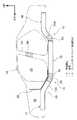
以下、本発明の実施の形態について、図面を基に詳細に説明する。なお、説明の便宜上、各図において適宜示す矢印UPを車体上方向、矢印FRを車体前方向、矢印OUTを車幅方向外側とする。また、以下の説明で、特記なく上下、前後、左右の方向を用いる場合は、車体上下方向の上下、車体前後方向の前後、車体左右方向(車幅方向)の左右を示すものとする。更に、図1では本実施形態に係る骨格構造10を備えた車両12の左側が示されているが、車両12の右側も左右対称で同様である。 Hereinafter, embodiments of the present invention will be described in detail with reference to the drawings. For convenience of explanation, an arrow UP appropriately shown in each drawing is an upward direction of the vehicle body, an arrow FR is a forward direction of the vehicle body, and an arrow OUT is an outer side of the vehicle width direction. Further, in the following description, when using the up / down, front / rear, and left / right directions, the vertical direction of the vehicle body, the front / rear direction of the vehicle body direction, and the left / right direction of the vehicle body (vehicle width direction) are indicated. Furthermore, although the left side of the
図1に示されるように、車両12の前部における両側部には、車体前後方向を長手方向とする左右一対のフロントサイドメンバ14が配設されている。各フロントサイドメンバ14は、閉断面形状とされた車両骨格部材であり、各フロントサイドメンバ14の長手方向中途部には、それぞれ傾斜部(キック部)14Aが形成されている。これにより、各フロントサイドメンバ14は、傾斜部14Aよりも車体前方側が車体後方側よりも所定高さ高い位置(高位)で車体前後方向に延在されている。 As shown in FIG. 1, a pair of left and right
また、車両12の後部における両側部には、車体前後方向を長手方向とする左右一対のリアフロアサイドメンバ16が配設されている。各リアフロアサイドメンバ16は、閉断面形状とされた車両骨格部材であり、各リアフロアサイドメンバ16の長手方向中途部には、それぞれ傾斜部(キック部)16Aが形成されている。これにより、各リアフロアサイドメンバ16は、各傾斜部16Aよりも車体後方側が車体前方側よりも所定高さ高い位置(高位)で車体前後方向に延在されている。 A pair of left and right rear
そして、フロントサイドメンバ14とリアフロアサイドメンバ16とは、車体前後方向に延在するフロアメンバ15を介して連続的かつ一体的に構成されており、各フロアメンバ15も、閉断面形状とされた車両骨格部材となっている。また、車両12には、エンジンコンパートメントルーム18と車室20とを区画する略平板状のダッシュパネル22が設けられている。 And the
なお、リアフロアサイドメンバ16側における骨格構造10は、フロントサイドメンバ14側における骨格構造10と同様であるため、以下においては、フロントサイドメンバ14側における骨格構造10を例に採って説明する。 Since the
<第1実施形態>
まず、第1実施形態について説明する。図2〜図4に示されるように、フロントサイドメンバ14は、ロアメンバ30とアッパメンバ40とを有している。ロアメンバ30は、深さの深い断面ハット型形状に鋼板等で成形されており、アッパメンバ40は、ロアメンバ30よりも深さの浅い断面ハット型形状に鋼板等で成形されている。<First Embodiment>
First, the first embodiment will be described. As shown in FIGS. 2 to 4, the
そして、図4に示されるように、ロアメンバ30の内壁36及び外壁38の上端部に、それぞれ車幅方向内側及び外側へ向けて連設されたフランジ部32と、アッパメンバ40の内壁46及び外壁48の下端部に、それぞれ車幅方向内側及び外側へ向けて連設されたフランジ部42と、がスポット溶接等によって接合されることで、フロントサイドメンバ14が閉断面形状に構成されている。 As shown in FIG. 4, a
また、図1に示されるように、フロントサイドメンバ14の傾斜部14Aにおける前端部と後端部(フロアメンバ15との境界部)は、それぞれ前側曲折部26と後側曲折部28とされている。前側曲折部26は、車体上方側へ凸状になるように予め屈曲又は湾曲された曲折部であり、後側曲折部28は、車体下方側へ凸状になるように予め屈曲又は湾曲された曲折部である。 As shown in FIG. 1, the front end portion and the rear end portion (boundary portion with the floor member 15) in the
したがって、車両12の前面衝突時等、フロントサイドメンバ14の前端部に車体後方側へ向かう荷重が入力されたときには、前側曲折部26が車体上方側へ折れ曲がり変形し(図4に示されるロアメンバ30の下壁34及び下壁34の車幅方向両端部である稜線部が車体上方側へ座屈変形し)、後側曲折部28が車体下方側へ折れ曲がり変形する(図4に示されるアッパメンバ40の上壁44及び上壁44の車幅方向両端部である稜線部が車体下方側へ座屈変形する)。 Accordingly, when a load toward the rear side of the vehicle body is input to the front end portion of the
つまり、前側曲折部26では、ロアメンバ30の下壁34が圧縮変形側(応力集中側)の壁部となり、アッパメンバ40の上壁44が引張変形側の壁部となる。そして、後側曲折部28では、アッパメンバ40の上壁44が圧縮変形側(応力集中側)の壁部となり、ロアメンバ30の下壁34が引張変形側の壁部となる。 That is, in the front
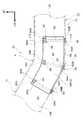
また、フロントサイドメンバ14の前側曲折部26及び後側曲折部28における閉断面形状内には、それぞれ繊維強化樹脂材(FRP)、例えばガラス繊維強化樹脂材(GFRP)や炭素繊維強化樹脂材(CFRP)で成形された補強部材50がインサート成形によって配設されている。なお、前側曲折部26と後側曲折部28に設けられる補強部材50は同等であるため、以下においては、後側曲折部28に設けられる補強部材50について説明する。 Further, in the closed cross-sectional shapes of the front
図2、図3に示されるように、後側曲折部28の閉断面形状内に設けられる補強部材50は、その曲折形状に合わせて成形されている。詳細に説明すると、後側曲折部28におけるロアメンバ30の内壁36及び外壁38の各フランジ部32に近接する上部には、車幅方向で対向する円形状の開口部36A、38Aが、ロアメンバ30の延在方向に所定の間隔を空けて複数組(図示のものは3組)形成されている。そして、車幅方向で各開口部36A、38Aと同位置となる下壁34の車幅方向中央部にも、それぞれ円形状の開口部34Aが形成されている。 As shown in FIGS. 2 and 3, the reinforcing
図2〜図4に示されるように、補強部材50は、ロアメンバ30の下壁34、内壁36、外壁38に沿って配置される断面略「U」字状の本体部52を有しており、本体部52の下壁54、内壁56、外壁58の各外面が、それぞれロアメンバ30の下壁34、内壁36、外壁38の各内面に密着されている。そして、本体部52の下壁54、内壁56、外壁58の外面上端部(開口側端部)には、それぞれインサート成形時に(成形過程で)各開口部34A、36A、38Aに取り外し不能に係合される係合部64、66、68が一体に形成されている。 As shown in FIGS. 2 to 4, the reinforcing
各係合部64、66、68の構成について、係合部66を例に採って説明すると、図5に示されるように、係合部66は、開口部36Aに挿通(係合)される円柱状の挿通部66Aと、挿通部66Aの断面積よりも大きい(開口部36Aを覆うことができる)面積とされ、内壁36の外面に内面が密着される矩形平板状のロック部66Bと、を有している。これにより、各係合部64、66、68が各開口部34A、36A、38Aから抜けない(強固に結合される)構成になっている。 The configuration of each of the engaging
なお、各開口部34A、36A、38Aの形状は、図示の円形状に限定されるものではない。したがって、各挿通部64A、66A、68Aの形状も、図示の円柱状に限定されるものではない。更に、ロック部64B、66B、68Bの形状も、図示の矩形平板状に限定されるものではなく、例えば円形平板状等に形成されていてもよい。また、各係合部64、66、68は、少なくとも本体部52の長手方向前端部及び後端部に形成されることが望ましい。 In addition, the shape of each opening
また、図2〜図5に示されるように、本体部52の内面側には、その長手方向に所定の間隔を空けて、複数の隔壁部60が一体に設けられている。各隔壁部60は、内壁56及び外壁58と同一高さの矩形平板状(下壁34、内壁36、外壁38で囲まれる断面四角形状)に形成されており、各係合部64、66、68と同位置(開口部34A、36A、38Aの中心を通る位置)に形成されている。 As shown in FIGS. 2 to 5, a plurality of
つまり、各隔壁部60の両側方における内壁56及び外壁58の外面上端部(開口側端部)に、それぞれ係合部66、68が一体に形成されており、隔壁部60の下方における下壁54の外面中央部に、係合部64が一体に形成されている。これにより、本体部52の各係合部64、66、68が形成されている部位の断面変形(本体部52のロアメンバ30からの剥がれ)が更に抑制又は防止されるとともに、各係合部64、66、68の強度(剛性)が向上される構成になっている。 That is, the engaging
そして、各係合部64、66、68と同位置に形成された各隔壁部60により、ロアメンバ30の各開口部34A、36A、38Aがそれぞれ形成されている下壁34、内壁36、外壁38の強度(剛性)低下が抑制される構成になっている。なお、各隔壁部60が形成される位置は、各係合部64、66、68と同位置とされることが望ましいが、その同位置から補強部材50の長手方向に若干ずれていても構わない。 The
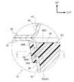
また、図6に示されるように、平面視で、係合部66が一体に形成された部位における内壁56の内面(係合部66とは表裏反対側の面)には、略円錐形状(平断面視で略「V」字状)に凹む窪み部66Cが形成されている。この窪み部66Cが形成される構成とすることにより、後述するように、係合部66において樹脂材内の繊維が絡み合うようになっている。 In addition, as shown in FIG. 6, the inner surface of the inner wall 56 (surface opposite to the engagement portion 66) at the portion where the
なお、図4に示されるように、係合部68が一体に形成された部位における外壁58の内面(係合部68とは表裏反対側の面)と、係合部64が一体に形成された部位における下壁54の内面(係合部64とは表裏反対側の面)にも、略円錐形状(平断面視で略「V」字状)に凹む窪み部68C、64Cがそれぞれ形成されており、後述するように、各係合部68、64においても樹脂材内の繊維が絡み合うようになっている。 As shown in FIG. 4, the inner surface of the outer wall 58 (surface opposite to the engaging portion 68) and the engaging
また、フロントサイドメンバ14の曲状部分である後側曲折部28に補強部材50を設ける場合には、図2、図3に示されるように、隔壁部60は、ロアメンバ30における最大曲折部P(正確な最大曲折部Pから多少ずれた位置も含む)に対応する本体部52の曲折部53にも形成されることが望ましい。 Further, when the reinforcing
つまり、直状部分に補強部材50を設ける場合には、隔壁部60は、少なくとも本体部52の長手方向前端部及び後端部に形成されていればよいが、曲状部分に補強部材50を設ける場合には、隔壁部60は、少なくとも本体部52の長手方向前端部及び後端部と曲折部53に形成されることが望ましい。これにより、本体部52の強度(剛性)が効率よく向上される。 That is, when the reinforcing
なお、隔壁部60の枚数に比例して本体部52の強度(剛性)が向上されるので、隔壁部60は、長手方向に所定の間隔を空けて更に形成されていてもよい。また、隔壁部60は、内壁56及び外壁58と同一高さに形成される構成に限定されるものではなく、内壁56及び外壁58より若干低く形成されていてもよい。 Since the strength (rigidity) of the
更に、隔壁部60は、下壁54との間に僅少な隙間を有する構成とされていてもよい。すなわち、隔壁部60は、内壁56と外壁58とを連結するような構成になっていてもよい。また、隔壁部60の板厚は、下壁54、内壁56、外壁58の板厚と同一とされていてもよいし、それより若干薄く又は厚く形成されていてもよい。 Further, the
また、補強部材50は、ロアメンバ30が予め配置された金型(図示省略)内に繊維強化樹脂材を射出して成形することより、ロアメンバ30と一体化されるようになっており、繊維強化樹脂材の注入口であったゲート跡(図示省略)は、本体部52の長手方向一端部側における車幅方向中央部に形成されている。つまり、この部位に相当する、金型のゲートから繊維強化樹脂材が流入されて補強部材50が成形されることにより、下壁54、内壁56、外壁58における繊維の配向が、それぞれの長手方向に沿うようになっている。 Further, the reinforcing
そして、これにより、補強部材50は、その長手方向(フロントサイドメンバ14の長手方向)における折れ曲がり変形時の引張強度が向上される構成になっている。なお、上記した金型のゲートから繊維強化樹脂材が流入されることにより、隔壁部60も一体に成形されるため、隔壁部60における繊維の配向は、その高さ方向にほぼ沿うようになっている。 And thereby, the
また、図6に示されるように、係合部66における繊維の配向は、補強部材50(本体部52)の長手方向に沿うとともに、内壁36の内面側と外面側とで絡み合う配向となっている。同様に、係合部68における繊維の配向は、補強部材50(本体部52)の長手方向に沿うとともに、外壁38の内面側と外面側とで絡み合う配向になっている。 Further, as shown in FIG. 6, the orientation of the fibers in the
詳細に説明すると、各係合部66、68が一体に形成された部位における内壁56の内面及び外壁58の内面には、それぞれ窪み部66C、68Cが形成されており、成形時には、樹脂材内の繊維が内面側から外面側へ(開口部36A、38A内へ)流れ易くなっている。つまり、成形時には、挿通部66A、68Aを成形する樹脂材内の繊維が、ロック部66B、68Bを成形する樹脂材内の繊維と絡み合うようになっており、これによって、係合部66、68の強度(剛性)が向上されるようになっている。 More specifically,
なお、係合部64が一体に形成された部位における下壁54の内面にも、窪み部64Cが形成されている。したがって、成形時には、挿通部64Aを成形する樹脂材内の繊維も、ロック部64Bを成形する樹脂材内の繊維と絡み合うようになっており、係合部64の強度(剛性)が向上されるようになっている。 A recessed
そして、このような構成とされた各係合部64、66、68により、各開口部34A、36A、38A周りの下壁34、内壁36、外壁38の強度(剛性)が補強され、ロアメンバ30に対して補強部材50が強固に結合されるようになっている。これにより、ロアメンバ30に荷重が入力されても(ロアメンバ30が変形しても)、補強部材50のロアメンバ30からの剥がれが抑制又は防止されるようになっている。 The strength (rigidity) of the
以上のような構成とされた第1実施形態に係る車両12の骨格構造10において、次にその作用について説明する。 Next, the operation of the
図示しない障壁に車両12が前面衝突(フルラップ衝突やオフセット衝突)した場合には、図示しないフロントバンパリインフォースメントやクラッシュボックスを介して、その衝撃による荷重がフロントサイドメンバ14の前端部に入力される。ここで、後側曲折部28は、予め屈曲又は湾曲されている曲折部であり、その最大曲折部Pが折れ曲がり変形の起点(変形起点)となっている。 When the
しかしながら、フロントサイドメンバ14の後側曲折部28(最大曲折部P)における閉断面形状内には、上記したように、補強部材50がインサート成形によって設けられている。すなわち、ロアメンバ30の下壁34、内壁36、外壁38にそれぞれ形成された開口部34A、36A、38Aに、成形過程で係合部64、66、68が取り外し不能に係合されることで、補強部材50がロアメンバ30に一体的に設けられている。 However, as described above, the reinforcing
したがって、フロントサイドメンバ14の前端部に荷重が入力され、後側曲折部28に対して、最大曲折部Pを変形起点として折れ曲がるような曲げモーメントが入力されても、補強部材50がロアメンバ30の内面から剥がれるのを効率よく抑制又は防止することができ、補強部材50(本体部52)において、その曲げモーメント(引張変形)に対する反力(抵抗力)を効率よく生じさせることができる。 Therefore, even if a load is input to the front end portion of the
しかも、補強部材50(本体部52)の繊維の配向は、ロアメンバ30の長手方向(荷重の入力方向)に沿っているため、補強部材50(本体部52)の繊維の配向が、ロアメンバ30の長手方向(荷重の入力方向)に沿っていない構成に比べて、入力された曲げモーメント(引張変形)に対する補強部材50(本体部52)の反力(抵抗力)を高めることができる。 In addition, since the fiber orientation of the reinforcing member 50 (main body portion 52) is along the longitudinal direction (load input direction) of the
よって、後側曲折部28に入力された曲げモーメント(引張変形)に対する補強部材50(本体部52)の強度(剛性)を向上させることができ、その曲げモーメント(引張変形)を効率よく抑制することができる。 Therefore, the strength (rigidity) of the reinforcing member 50 (main body portion 52) with respect to the bending moment (tensile deformation) input to the rear
また、後側曲折部28の最大曲折部Pに対応する補強部材50(本体部52)の曲折部53には、隔壁部60が一体に立設されている。したがって、補強部材50(本体部52)の座屈耐力を向上させることができ、補強部材50(本体部52)の断面変形(座屈変形)を抑制することができる。 In addition, a
つまり、内壁36の車幅方向内側へ凸となる断面変形(座屈変形)や外壁38の車幅方向外側へ凸となる断面変形(座屈変形)を抑制することができる。よって、フロントサイドメンバ14(傾斜部14A)の後側曲折部28(最大曲折部P)を変形起点とした折れ曲がり変形(塑性変形)領域の強度(剛性)を向上させることができ、その折れ曲がり変形を効果的に抑制(緩和)することができる。 That is, it is possible to suppress cross-sectional deformation (buckling deformation) that protrudes inward in the vehicle width direction of the
そして、これにより、車両12の前面衝突時において、後側曲折部28よりも車体前方側のフロントサイドメンバ14を、その軸方向(車体前後方向)に効率よく圧縮変形させる(潰れさせる)ことができる。したがって、入力された衝突荷重をフロントサイドメンバ14の直状部分で効率よく吸収させることができる。 As a result, at the time of a frontal collision of the
換言すれば、この補強部材50により、フロントサイドメンバ14の前端部に入力された荷重によって折れ曲がり変形されようとする後側曲折部28(折れ曲がり変形の発生が予測される部位)を局所的に効率よく補強することができるので、フロントサイドメンバ14の軸方向の圧縮変形不良及び後側曲折部28の折れ曲がり変形量の増大に伴う衝突安全性能の低下を抑制又は防止することができる。 In other words, the reinforcing
このように、第1実施形態に係る車両12の骨格構造10によれば、車両12の前面衝突時において、車室20の変形を抑制又は防止することができ、車室20の前後方向の空間を広く確保することができる。しかも、この補強部材50は、繊維強化樹脂製とされて軽量化されているため、板金等で補強されている構造に比べて、燃費を向上させることができるとともに、排気ガスを低減させることができる。 Thus, according to the
また、この補強部材50により、車体の剛性低下を抑制することができ、後側曲折部28の弾性変形領域の強度(剛性)も向上させることができるので、車両12の走行時において、車両12に生じる振動や騒音、更には車両12の操縦安定性能の低下を抑制又は防止することができる。なお、リアフロアサイドメンバ16における前側曲折部に補強部材50を設けた場合の作用も同様である。 Further, the reinforcing
また、補強部材50は、繊維強化樹脂製とされて軽量化されているので、車両12の骨格を構成する閉断面形状の骨格部材のうち、予め屈曲又は湾曲されている曲折部ではなく、車両12の衝突時に折れ曲がり変形の発生が予測される全ての部位に設けることが可能である。例えば図1に示されるように、車体上下方向へ略直状に延在するセンターピラー24等の閉断面形状内に設けることが可能である。 Further, since the reinforcing
予め屈曲又は湾曲されていない部位の一例であるセンターピラー24の閉断面形状内に補強部材50を設ける場合には、車両12の側面衝突時に折れ曲がり変形が発生すると予測されるセンターピラー24の所定部位におけるインナパネル(図示省略)の内面に、インサート成形によって補強部材50を一体的に設ければよい。 In the case where the reinforcing
このような構成によれば、車両12が側面衝突し、センターピラー24の所定部位が車幅方向内側へ折れ曲がり変形(座屈変形)すると、インナパネル側が引張変形側となるため、補強部材50が、その長手方向、即ち繊維の配向方向に沿って引っ張られる。しかしながら、補強部材50には、その引張変形に対する反力(抵抗力)が生じるので、センターピラー24の車幅方向内側への折れ曲がり変形を抑制することができる。 According to such a configuration, when the
しかも、補強部材50は、隔壁部60によって断面変形が抑制されているので、センターピラー24の断面変形が抑制される。つまり、隔壁部60を備えた補強部材50により、センターピラー24の車幅方向内側への折れ曲がり変形がより効果的に抑制される。したがって、車両12の側面衝突時における車室20の変形をより効果的に抑制することができる。 In addition, since the cross-sectional deformation of the reinforcing
<第2実施形態>
次に、第2実施形態について説明する。なお、第2実施形態において、上記第1実施形態と同等の部位には、同じ符号を付して詳細な説明(共通する作用も含む)は適宜省略する。Second Embodiment
Next, a second embodiment will be described. Note that in the second embodiment, the same portions as those in the first embodiment are denoted by the same reference numerals, and detailed description (including common actions) is omitted as appropriate.
第2実施形態におけるロアメンバ30は、係合部64、66、68が設けられる開口部34A、36A、38A周りの下壁34、内壁36、外壁38の形状が、第1実施形態におけるロアメンバ30の下壁34、内壁36、外壁38とは異なっている。なお、下壁34、内壁36、外壁38の各開口部34A、36A、38A周りの形状は同一なので、ここでは下壁34を例に採って説明する。 The
図7に示されるように、ロアメンバ30の下壁34の開口部34A周りは、閉断面形状内へ向かって略円錐台形状に凹む凹部34Bとされており、係合部64におけるロック部64Bが、その凹部34B内に配置されている。凹部34Bの深さは、ロック部64Bの厚さ以上とされており、そのロック部64Bが、下壁34の外面よりも下方側(外方側)へ突出するのが抑制又は防止される構成になっている。 As shown in FIG. 7, the periphery of the
したがって、ロアメンバ30(フロントサイドメンバ14)の外面側(車幅方向内側及び外側と車体上下方向下側)にスペースがなくても、補強部材50をロアメンバ30の下壁34、内壁36、外壁38の内面側に、インサート成形によって一体的に設けることが可能となっている。 Therefore, even if there is no space on the outer surface side (the vehicle width direction inner side and the outer side and the vehicle body vertical direction lower side) of the lower member 30 (front side member 14), the reinforcing
<第3実施形態>
次に、第3実施形態について説明する。なお、第3実施形態において、上記第1実施形態及び第2実施形態と同等の部位には、同じ符号を付して詳細な説明(共通する作用も含む)は適宜省略する。<Third Embodiment>
Next, a third embodiment will be described. Note that in the third embodiment, parts that are the same as in the first and second embodiments are given the same reference numerals, and detailed descriptions (including common actions) are omitted as appropriate.
図8に示されるように、第3実施形態におけるロアメンバ30は、第1実施形態におけるロアメンバ30よりも深さが浅く形成されており、その内壁36及び外壁38の車体上下方向中央部に、それぞれ下部側が上部側よりも閉断面形状内へ凹む段差部36B、38Bが形成されている。 As shown in FIG. 8, the
そして、内壁36の下部側に開口部36Aが形成され、外壁38の下部側に開口部38Aが形成されており、段差部36B、38Bの深さ(車幅方向の高さ)がロック部66B、68Bの厚さ以上とされている。したがって、ロック部66Bが、内壁36の上部外面よりも車幅方向内側(外方側)へ突出するのが抑制又は防止され、ロック部68Bが、外壁38の上部外面よりも車幅方向外側(外方側)へ突出するのが抑制又は防止されている。 An
これにより、ロアメンバ30(フロントサイドメンバ14)の外面側(車幅方向内側及び外側)にスペースがなくても、補強部材50をロアメンバ30の下壁34、内壁36、外壁38の内面側に、インサート成形によって一体的に設けることが可能となっている。 Thereby, even if there is no space on the outer surface side (vehicle width direction inner side and outer side) of the lower member 30 (front side member 14), the reinforcing
そして、この第3実施形態における補強部材50では、複数の隔壁部60の代わりに、複数の補強リブ62が本体部52の内面に一体に突設されている。詳細に説明すると、各補強リブ62は、断面略「U」字状に形成されており、下壁54、内壁56、外壁58の内面に沿って所定の高さで一体に形成されている。 In the reinforcing
この補強リブ62により、補強部材50(各係合部64、66、68を含む)の強度(剛性)が向上され、ロアメンバ30の各開口部34A、36A、38Aがそれぞれ形成されている下壁34、内壁36、外壁38の強度(剛性)低下が抑制される構成になっている。なお、補強リブ62の厚さは、隔壁部60の厚さと同等でもよいし、異なっていてもよい。 The reinforcing
また、この第3実施形態では、ロアメンバ30の深さが浅いため、ロアメンバ30の強度(剛性)が向上されている。よって、隔壁部60よりも高さの低い補強リブ62にしても、ロアメンバ30(補強部材50)の断面変形を抑制することができる。なお、第3実施形態における補強リブ62は、本体部52の内面側(閉断面形状内)に隔壁部60を設けることが不可能な場合に適用できる利点がある。 In the third embodiment, since the depth of the
<第4実施形態>
最後に、第4実施形態について説明する。なお、第4実施形態において、上記第1実施形態〜第3実施形態と同等の部位には、同じ符号を付して詳細な説明(共通する作用も含む)は適宜省略する。<Fourth embodiment>
Finally, a fourth embodiment will be described. Note that in the fourth embodiment, parts that are the same as in the first to third embodiments are given the same reference numerals, and detailed descriptions (including common actions) are omitted as appropriate.
図9に示されるように、第4実施形態では、第3実施形態におけるロアメンバ30の下壁34、内壁36、外壁38の下部外面側に、補強部材50がインサート成形によって一体的に設けられている。すなわち、各係合部66、68は、それぞれ内壁36の下部側に形成された開口部36A及び外壁38の下部側に形成された開口部38Aに外面側から係合され、各ロック部66B、68Bは、ロアメンバ30の内面側(閉断面形状内)に配置されている。 As shown in FIG. 9, in the fourth embodiment, the reinforcing
そして、各ロック部66B、68Bの下端部は、ロアメンバ30の下壁34の内面に当接されている。つまり、各ロック部66B、68Bの面積が第1実施形態〜第3実施形態におけるロック部66B、68Bの面積よりも大きくされている。これにより、ロアメンバ30の内壁36の下部側が、本体部52の内壁56とロック部66Bとで挟持固定され、ロアメンバ30の外壁38の下部側が、本体部52の外壁58とロック部68Bとで挟持固定されるようになっている。 The lower ends of the
すなわち、補強部材50は、ロアメンバ30の下壁34、内壁36、外壁38の下部外面側に強固に結合されるようになっている。したがって、フロントサイドメンバ14の前端部に荷重が入力され、後側曲折部28に対して、最大曲折部Pを変形起点として折れ曲がるような曲げモーメントが入力されても、補強部材50がロアメンバ30の外面から剥がれるのが抑制又は防止される。 That is, the reinforcing
また、補強部材50の内壁56及び外壁58は、内壁36の下部側及び外壁38の下部側にそれぞれ形成された段差部36B、38Bに配置されており、少なくとも内壁56及び外壁58の厚さは、段差部36B、38Bの深さ(車幅方向の高さ)以下とされている。したがって、内壁56が、内壁36の上部外面よりも車幅方向内側(外方側)へ突出するのが抑制又は防止され、外壁58が、外壁38の上部外面よりも車幅方向外側(外方側)へ突出するのが抑制又は防止されている。 Further, the
これにより、ロアメンバ30(フロントサイドメンバ14)の外面側(車幅方向内側及び外側)にスペースがなくても、補強部材50をロアメンバ30の下壁34、内壁36、外壁38の外面側に、インサート成形によって一体的に設けることが可能となっている。なお、第4実施形態における補強部材50の場合は、挿通部66A、68Aに対して表裏反対側の面となる内壁56の外面及び外壁58の外面に、それぞれ窪み部66C、68Cが形成される。 Thereby, even if there is no space on the outer surface side (vehicle width direction inner side and outer side) of the lower member 30 (front side member 14), the reinforcing
以上、本実施形態に係る車両12の骨格構造10について、図面を基に説明したが、本実施形態に係る車両12の骨格構造10は、図示のものに限定されるものではなく、本発明の要旨を逸脱しない範囲内において、適宜設計変更可能なものである。例えば、第2実施形態〜第4実施形態をセンターピラー24に適用してもよい。すなわち、第2実施形態〜第4実施形態における補強部材50をセンターピラー24のインナパネルにインサート成形によって設けるようにしてもよい。 Although the
また、補強部材50は、インサート成形によってフロントサイドメンバ14のロアメンバ30やセンターピラー24のインナパネルに一体的に設けられる構成に限定されるものではない。例えば、フロントサイドメンバ14のロアメンバ30やセンターピラー24のインナパネルに繊維強化樹脂材を積層して貼り付け、その後、熱硬化させて一体的に設ける構成にしてもよい。 Further, the reinforcing
つまり、補強部材50は、その成形過程で、フロントサイドメンバ14やセンターピラー24に一体的に設けられる構成になっていればよい。また、ロアメンバ30と同様に、アッパメンバ40側にも補強部材50を一体的に設ける構成にしてもよい。この場合、アッパメンバ40の内壁46及び外壁48の各フランジ部42に近接する下部に、車幅方向で対向する開口部(図示省略)が形成され、車幅方向で各開口部と同位置となる上壁44の車幅方向中央部に開口部(図示省略)が形成されればよい。 That is, the reinforcing
10 骨格構造
12 車両
14 フロントサイドメンバ(骨格部材)
34 下壁(壁部)
34A 開口部
34B 凹部
36 内壁(壁部)
36A 開口部
38 外壁(壁部)
38A 開口部
50 補強部材
52 本体部
60 隔壁部
62 補強リブ
64 係合部
64A 挿通部
64B ロック部
64C 窪み部
66 係合部
66A 挿通部
66B ロック部
66C 窪み部
68 係合部
68A 挿通部
68B ロック部
68C 窪み部10
34 Lower wall (wall)
Claims (9)
Translated fromJapanese前記開口部に挿通された挿通部と前記開口部よりも大きい面積とされたロック部とを有する係合部が一体に形成され、少なくとも前記開口部を有する壁部に沿って配置された繊維強化樹脂製の補強部材と、
を備え、
前記補強部材は、前記係合部とは表裏反対側の面に窪み部を有する車両の骨格構造。A skeleton member which is formed in a closed cross-sectional shape by a plurality of wall portions and has an opening formed in at least a part of the plurality of wall portions, and constituting a skeleton of the vehicle;
A fiber reinforcement in which an engaging portion having an insertion portion inserted through the opening and a lock portion having a larger area than the opening is integrally formed, and is arranged along at least the wall portion having the opening. A resin reinforcing member;
Equipped witha,
The reinforcing member is a skeleton structureof a vehiclehaving a recessed portion on a surface opposite to the engagement portion .
Priority Applications (2)
| Application Number | Priority Date | Filing Date | Title |
|---|---|---|---|
| JP2014004624AJP5928491B2 (en) | 2014-01-14 | 2014-01-14 | Vehicle skeleton structure |
| US14/578,952US9340237B2 (en) | 2014-01-14 | 2014-12-22 | Frame structure of vehicle |
Applications Claiming Priority (1)
| Application Number | Priority Date | Filing Date | Title |
|---|---|---|---|
| JP2014004624AJP5928491B2 (en) | 2014-01-14 | 2014-01-14 | Vehicle skeleton structure |
Publications (2)
| Publication Number | Publication Date |
|---|---|
| JP2015131590A JP2015131590A (en) | 2015-07-23 |
| JP5928491B2true JP5928491B2 (en) | 2016-06-01 |
Family
ID=53520686
Family Applications (1)
| Application Number | Title | Priority Date | Filing Date |
|---|---|---|---|
| JP2014004624AExpired - Fee RelatedJP5928491B2 (en) | 2014-01-14 | 2014-01-14 | Vehicle skeleton structure |
Country Status (2)
| Country | Link |
|---|---|
| US (1) | US9340237B2 (en) |
| JP (1) | JP5928491B2 (en) |
Families Citing this family (15)
| Publication number | Priority date | Publication date | Assignee | Title |
|---|---|---|---|---|
| JP5962627B2 (en)* | 2013-09-27 | 2016-08-03 | トヨタ自動車株式会社 | Body reinforcement structure |
| JP6176086B2 (en)* | 2013-11-28 | 2017-08-09 | トヨタ自動車株式会社 | Lower body structure |
| JP6109271B2 (en)* | 2015-02-06 | 2017-04-05 | 株式会社神戸製鋼所 | Junction structure and manufacturing method of junction structure |
| US9758193B2 (en)* | 2015-02-10 | 2017-09-12 | Honda Motor Co., Ltd. | Structural reinforcement member for a vehicle body |
| EP3321137B1 (en)* | 2015-07-08 | 2020-06-10 | Nippon Steel Corporation | Bumper reinforcement and vehicle provided with same |
| DE102016001241A1 (en)* | 2016-02-04 | 2017-08-10 | GM Global Technology Operations LLC (n. d. Ges. d. Staates Delaware) | Structure node for a motor vehicle body |
| US10414446B2 (en)* | 2016-04-22 | 2019-09-17 | Honda Motor Co., Ltd. | Lightweight vehicle pan assembly and method for attachment to vehicle frame via welding |
| FR3056144B1 (en)* | 2016-09-16 | 2018-10-12 | Plastic Omnium Cie | IMPROVED MANUFACTURING METHOD OF A HYBRID STRUCTURE OF A MOTOR VEHICLE AND CORRESPONDING HYBRID STRUCTURE PIECE |
| JP6855851B2 (en)* | 2017-03-13 | 2021-04-07 | 日本製鉄株式会社 | Structural members for vehicles |
| CN114906232B (en) | 2017-04-10 | 2025-02-11 | 沙特基础工业全球技术有限公司 | Hybrid structure and manufacturing method |
| JP6908118B2 (en)* | 2017-09-01 | 2021-07-21 | 日本製鉄株式会社 | Hollow member |
| WO2019224976A1 (en)* | 2018-05-24 | 2019-11-28 | 日産自動車株式会社 | Automobile part |
| WO2020003382A1 (en) | 2018-06-26 | 2020-01-02 | 日産自動車株式会社 | Composite |
| EP3912890B1 (en)* | 2019-01-18 | 2024-04-03 | NISSAN MOTOR Co., Ltd. | Vehicle body structure |
| JP7587944B2 (en)* | 2020-09-03 | 2024-11-21 | プレス工業株式会社 | Vehicle body frame member and method for manufacturing vehicle body frame member |
Family Cites Families (50)
| Publication number | Priority date | Publication date | Assignee | Title |
|---|---|---|---|---|
| US3724153A (en)* | 1971-01-19 | 1973-04-03 | Budd Co | Joint construction |
| US4826238A (en)* | 1986-12-01 | 1989-05-02 | Honda Giken Kogyo Kabushiki Kaisha | Side sill for automotive vehicle |
| US5212208A (en)* | 1989-02-13 | 1993-05-18 | Exxon Chemical Patents Inc. | Process of insulating a body cavity |
| US5173142A (en)* | 1991-07-19 | 1992-12-22 | Wellman Machinery Of Michigan, Inc. | Method of making reinforced structural composite assemblies |
| US5338588A (en)* | 1991-07-19 | 1994-08-16 | Ticom Corporation | Method of making reinforced structural composite assemblies and assembly produced thereby |
| JPH07315247A (en)* | 1994-05-24 | 1995-12-05 | Honda Motor Co Ltd | Vehicle structural members |
| JP3132294B2 (en)* | 1994-07-15 | 2001-02-05 | 日産自動車株式会社 | Cabin frame structure of vehicle body |
| US6341467B1 (en)* | 1996-05-10 | 2002-01-29 | Henkel Corporation | Internal reinforcement for hollow structural elements |
| US6270600B1 (en)* | 1996-07-03 | 2001-08-07 | Henkel Corporation | Reinforced channel-shaped structural member methods |
| JPH10264855A (en)* | 1997-03-26 | 1998-10-06 | Aisin Seiki Co Ltd | Vehicle front-end module structure |
| JPH10278840A (en)* | 1997-04-11 | 1998-10-20 | Suzuki Motor Corp | Car body structure |
| US6233826B1 (en)* | 1997-07-21 | 2001-05-22 | Henkel Corp | Method for reinforcing structural members |
| US6199941B1 (en)* | 1998-05-08 | 2001-03-13 | Toyota Jidosha Kabushiki Kaisha | Impact energy absorbing structure in upper vehicle body portion and impact energy absorbing member |
| US6267436B1 (en)* | 1998-07-22 | 2001-07-31 | Toyota Jidosha Kabushiki Kaisha | Impact energy absorbing structure in upper vehicle body portion, and impact energy absorbing component |
| KR20010049950A (en)* | 1999-08-05 | 2001-06-15 | 제임스 이. 미러 | Frame structure of vehicle body |
| JP4476438B2 (en)* | 1999-11-12 | 2010-06-09 | 株式会社ネオックスラボ | Hollow structure reinforcement |
| US6296301B1 (en)* | 1999-12-21 | 2001-10-02 | Daimlerchrysler Corporation | Motor vehicle body structure using a woven fiber |
| JP3428545B2 (en)* | 2000-01-07 | 2003-07-22 | 本田技研工業株式会社 | Body reinforcement structure |
| US6467834B1 (en)* | 2000-02-11 | 2002-10-22 | L&L Products | Structural reinforcement system for automotive vehicles |
| JP2002012167A (en) | 2000-04-26 | 2002-01-15 | Neoex Lab Inc | Reinforcing structure of hollow structure and reinforcing tool therefor |
| DE10143557A1 (en)* | 2001-09-06 | 2003-04-03 | Daimler Chrysler Ag | Process for producing a structural element |
| US6786533B2 (en)* | 2001-09-24 | 2004-09-07 | L&L Products, Inc. | Structural reinforcement system having modular segmented characteristics |
| US6793183B1 (en)* | 2003-04-10 | 2004-09-21 | The Boeing Company | Integral node tubular spaceframe |
| JP4548207B2 (en)* | 2005-04-28 | 2010-09-22 | スズキ株式会社 | Cushioning member mounting structure in vehicle roof |
| EP1762466B1 (en)* | 2005-09-08 | 2009-03-25 | Ford Global Technologies, LLC | Impact energy absorption block arrangement |
| JP4483830B2 (en)* | 2006-05-29 | 2010-06-16 | トヨタ自動車株式会社 | Lower body structure |
| JP4788539B2 (en)* | 2006-09-13 | 2011-10-05 | トヨタ自動車株式会社 | Body panel structure |
| US7445269B2 (en)* | 2006-12-14 | 2008-11-04 | Ford Global Technologies, Llc | Structural stability device for automotive frame members |
| JP5153226B2 (en)* | 2007-06-25 | 2013-02-27 | 日産自動車株式会社 | Energy absorbing structure and energy absorbing method |
| US7735906B2 (en)* | 2007-09-28 | 2010-06-15 | Zephyros, Inc. | Reinforcement system for an automotive vehicle |
| JP4380760B2 (en)* | 2007-11-28 | 2009-12-09 | トヨタ自動車株式会社 | Sheet holder structure |
| EP2159109A1 (en) | 2008-09-01 | 2010-03-03 | Sika Technology AG | Reinforcement with channel design |
| DE102009005763A1 (en)* | 2009-01-23 | 2010-07-29 | Lanxess Deutschland Gmbh | Frame side part of a motor vehicle body |
| EP2289771B2 (en)* | 2009-08-27 | 2017-10-11 | Sika Technology AG | Structural reinforcer with bonding material on orthoganal surfaces |
| US8545956B2 (en)* | 2010-04-26 | 2013-10-01 | Sika Technology Ag | Expandable insert with flexible substrate |
| US20130187406A1 (en)* | 2010-09-28 | 2013-07-25 | Toyota Jidosha Kabushiki Kaisha | Vehicle body structure |
| JP5516345B2 (en)* | 2010-11-11 | 2014-06-11 | マツダ株式会社 | Vehicle frame structure |
| US20120256445A1 (en)* | 2011-04-05 | 2012-10-11 | Ridha Baccouche | Vehicle roof support pillar |
| JP5797496B2 (en) | 2011-08-24 | 2015-10-21 | 本田技研工業株式会社 | Bonding structure of resin plate material and bonding method of resin plate material |
| JP5812119B2 (en)* | 2012-01-18 | 2015-11-11 | トヨタ自動車株式会社 | Lower body structure |
| JP5891827B2 (en)* | 2012-02-08 | 2016-03-23 | マツダ株式会社 | Lower body structure of the car body |
| JP2013212730A (en) | 2012-03-30 | 2013-10-17 | Fuji Heavy Ind Ltd | Vehicle |
| DE102013203337A1 (en)* | 2012-03-30 | 2013-10-02 | Fuji Jukogyo K.K. | vehicle |
| JP6172848B2 (en)* | 2012-09-26 | 2017-08-02 | 株式会社Subaru | vehicle |
| JP6148915B2 (en)* | 2012-09-26 | 2017-06-14 | 株式会社Subaru | vehicle |
| KR101428273B1 (en)* | 2012-12-12 | 2014-08-07 | 현대자동차주식회사 | Reinforcing structure of package tray side member for vehivcle |
| US9033404B2 (en)* | 2013-03-14 | 2015-05-19 | Honda Motor Co., Ltd. | Encapsulated aluminum honeycomb structural stiffener |
| JP5768838B2 (en)* | 2013-06-17 | 2015-08-26 | トヨタ自動車株式会社 | Vehicle skeleton structure |
| US8911008B1 (en)* | 2013-08-30 | 2014-12-16 | Honda Motor Co., Ltd. | Acoustic spray foam control system and method |
| JP6048458B2 (en)* | 2014-07-25 | 2016-12-21 | トヨタ自動車株式会社 | Vehicle panel joint structure |
- 2014
- 2014-01-14JPJP2014004624Apatent/JP5928491B2/ennot_activeExpired - Fee Related
- 2014-12-22USUS14/578,952patent/US9340237B2/ennot_activeExpired - Fee Related
Also Published As
| Publication number | Publication date |
|---|---|
| JP2015131590A (en) | 2015-07-23 |
| US20150197289A1 (en) | 2015-07-16 |
| US9340237B2 (en) | 2016-05-17 |
Similar Documents
| Publication | Publication Date | Title |
|---|---|---|
| JP5928491B2 (en) | Vehicle skeleton structure | |
| JP5924321B2 (en) | Vehicle skeleton structure | |
| JP5768838B2 (en) | Vehicle skeleton structure | |
| CN108116508B (en) | Body Substructure | |
| JP6555235B2 (en) | Lower body structure | |
| JP5924334B2 (en) | Bonding structure of dissimilar materials | |
| JP5983583B2 (en) | Vehicle skeleton structure | |
| JP5900481B2 (en) | Vehicle panel structure | |
| JP5516361B2 (en) | Vehicle side sill structure | |
| JP5533587B2 (en) | Vehicle side sill structure | |
| CN105905169B (en) | The front-body structure of vehicle | |
| JP6020381B2 (en) | Vehicle skeleton structure | |
| JP6612684B2 (en) | Car body side structure | |
| JP2007314131A (en) | Lower body structure | |
| US8979176B2 (en) | Steering support member | |
| JP2009113766A (en) | Body side structure | |
| JP2018030542A (en) | Vehicle components | |
| JP6019084B2 (en) | Body side structure | |
| JP2012056407A (en) | Reinforcing structure in vehicle body framework for vehicle | |
| JP6225800B2 (en) | Vehicle energy absorption structure | |
| JP5093094B2 (en) | Connection structure between dash panel and tunnel | |
| JP2015110397A (en) | Vehicle body resin panel structure | |
| JP2010030339A (en) | Reinforcement structure for vehicle skeleton member | |
| CN106364558B (en) | Front car body and method of manufacturing front car body | |
| JP2007190960A (en) | Body front structure |
Legal Events
| Date | Code | Title | Description |
|---|---|---|---|
| A977 | Report on retrieval | Free format text:JAPANESE INTERMEDIATE CODE: A971007 Effective date:20151109 | |
| A131 | Notification of reasons for refusal | Free format text:JAPANESE INTERMEDIATE CODE: A131 Effective date:20151208 | |
| A521 | Request for written amendment filed | Free format text:JAPANESE INTERMEDIATE CODE: A523 Effective date:20160108 | |
| TRDD | Decision of grant or rejection written | ||
| A01 | Written decision to grant a patent or to grant a registration (utility model) | Free format text:JAPANESE INTERMEDIATE CODE: A01 Effective date:20160329 | |
| A61 | First payment of annual fees (during grant procedure) | Free format text:JAPANESE INTERMEDIATE CODE: A61 Effective date:20160411 | |
| R151 | Written notification of patent or utility model registration | Ref document number:5928491 Country of ref document:JP Free format text:JAPANESE INTERMEDIATE CODE: R151 | |
| LAPS | Cancellation because of no payment of annual fees |