JP5925320B2 - Stopcock flow path switching device - Google Patents
Stopcock flow path switching deviceDownload PDFInfo
- Publication number
- JP5925320B2 JP5925320B2JP2014527864AJP2014527864AJP5925320B2JP 5925320 B2JP5925320 B2JP 5925320B2JP 2014527864 AJP2014527864 AJP 2014527864AJP 2014527864 AJP2014527864 AJP 2014527864AJP 5925320 B2JP5925320 B2JP 5925320B2
- Authority
- JP
- Japan
- Prior art keywords
- flow path
- tube
- blood pressure
- valve body
- switching
- Prior art date
- Legal status (The legal status is an assumption and is not a legal conclusion. Google has not performed a legal analysis and makes no representation as to the accuracy of the status listed.)
- Active
Links
- HAFZSBASGRZPLA-UHFFFAOYSA-NCCC(C)N(C)CCChemical compoundCCC(C)N(C)CCHAFZSBASGRZPLA-UHFFFAOYSA-N0.000description1
Images


Classifications
- A—HUMAN NECESSITIES
- A61—MEDICAL OR VETERINARY SCIENCE; HYGIENE
- A61M—DEVICES FOR INTRODUCING MEDIA INTO, OR ONTO, THE BODY; DEVICES FOR TRANSDUCING BODY MEDIA OR FOR TAKING MEDIA FROM THE BODY; DEVICES FOR PRODUCING OR ENDING SLEEP OR STUPOR
- A61M39/00—Tubes, tube connectors, tube couplings, valves, access sites or the like, specially adapted for medical use
- A61M39/22—Valves or arrangement of valves
- A61M39/223—Multiway valves
- A—HUMAN NECESSITIES
- A61—MEDICAL OR VETERINARY SCIENCE; HYGIENE
- A61B—DIAGNOSIS; SURGERY; IDENTIFICATION
- A61B5/00—Measuring for diagnostic purposes; Identification of persons
- A61B5/02—Detecting, measuring or recording for evaluating the cardiovascular system, e.g. pulse, heart rate, blood pressure or blood flow
- A61B5/021—Measuring pressure in heart or blood vessels
- A61B5/02141—Details of apparatus construction, e.g. pump units or housings therefor, cuff pressurising systems, arrangements of fluid conduits or circuits
- A—HUMAN NECESSITIES
- A61—MEDICAL OR VETERINARY SCIENCE; HYGIENE
- A61B—DIAGNOSIS; SURGERY; IDENTIFICATION
- A61B5/00—Measuring for diagnostic purposes; Identification of persons
- A61B5/02—Detecting, measuring or recording for evaluating the cardiovascular system, e.g. pulse, heart rate, blood pressure or blood flow
- A61B5/021—Measuring pressure in heart or blood vessels
- A61B5/0215—Measuring pressure in heart or blood vessels by means inserted into the body
- A—HUMAN NECESSITIES
- A61—MEDICAL OR VETERINARY SCIENCE; HYGIENE
- A61M—DEVICES FOR INTRODUCING MEDIA INTO, OR ONTO, THE BODY; DEVICES FOR TRANSDUCING BODY MEDIA OR FOR TAKING MEDIA FROM THE BODY; DEVICES FOR PRODUCING OR ENDING SLEEP OR STUPOR
- A61M5/00—Devices for bringing media into the body in a subcutaneous, intra-vascular or intramuscular way; Accessories therefor, e.g. filling or cleaning devices, arm-rests
- A61M5/007—Devices for bringing media into the body in a subcutaneous, intra-vascular or intramuscular way; Accessories therefor, e.g. filling or cleaning devices, arm-rests for contrast media
- A—HUMAN NECESSITIES
- A61—MEDICAL OR VETERINARY SCIENCE; HYGIENE
- A61M—DEVICES FOR INTRODUCING MEDIA INTO, OR ONTO, THE BODY; DEVICES FOR TRANSDUCING BODY MEDIA OR FOR TAKING MEDIA FROM THE BODY; DEVICES FOR PRODUCING OR ENDING SLEEP OR STUPOR
- A61M39/00—Tubes, tube connectors, tube couplings, valves, access sites or the like, specially adapted for medical use
- A61M39/22—Valves or arrangement of valves
- A61M2039/229—Stopcocks
Landscapes
- Health & Medical Sciences (AREA)
- Life Sciences & Earth Sciences (AREA)
- Heart & Thoracic Surgery (AREA)
- Public Health (AREA)
- Veterinary Medicine (AREA)
- Biomedical Technology (AREA)
- Engineering & Computer Science (AREA)
- Animal Behavior & Ethology (AREA)
- General Health & Medical Sciences (AREA)
- Cardiology (AREA)
- Vascular Medicine (AREA)
- Anesthesiology (AREA)
- Hematology (AREA)
- Physiology (AREA)
- Physics & Mathematics (AREA)
- Biophysics (AREA)
- Pathology (AREA)
- Medical Informatics (AREA)
- Molecular Biology (AREA)
- Surgery (AREA)
- Pulmonology (AREA)
- Infusion, Injection, And Reservoir Apparatuses (AREA)
- Apparatus For Radiation Diagnosis (AREA)
Description
Translated fromJapaneseこの発明は、患者に造影剤、その他の薬液を導入するためのインジェクタヘッドに連結される活栓流路切替装置に関する。 The present invention relates to a stopcock flow path switching device connected to an injector head for introducing a contrast medium and other chemicals into a patient.
心臓カテーテル検査においては、インジェクタヘッドを用いて患者に造影剤が導入され、患部が造影された状態で検査が行なわれる。たとえば、心臓の血管を造影する冠動脈造影では、狭窄した病変部を、カテーテル法を使って拡張する血管内の手術が行なわれる。心臓の左心室を造影する左心室造影では、心臓の収縮と拡張との様子から、左心室の周りの心筋の動きを検査する。 In a cardiac catheter test, a contrast medium is introduced into a patient using an injector head, and the test is performed in a state where an affected area is imaged. For example, in coronary angiography for imaging the blood vessels of the heart, an intravascular operation is performed in which a narrowed lesion is expanded using a catheter method. In left ventricular imaging that contrasts the left ventricle of the heart, the motion of the myocardium around the left ventricle is examined from the state of contraction and expansion of the heart.
このようなインジェクタヘッドは、たとえば、特開平10−165396号公報(特許文献1)および特開平10−244002号公報(特許文献2)に開示されている。 Such injector heads are disclosed in, for example, Japanese Patent Application Laid-Open No. 10-165396 (Patent Document 1) and Japanese Patent Application Laid-Open No. 10-244002 (Patent Document 2).
インジェクタヘッドを用いて検査を行なう場合には、適宜、患者の血圧測定が行なわれる。患者の血圧測定には、血圧トランスジューサが用いられる。インジェクタヘッドから造影剤を患者に導入する流路の途中領域には、患者とインジェクタヘッドとを連結する流路(以下、造影剤導入流路)と、患者とトランスジューサとを連結する流路(以下、血圧測定流路)とを切り替える切替機構が設けられる。 When a test is performed using an injector head, the patient's blood pressure is appropriately measured. A blood pressure transducer is used to measure a patient's blood pressure. In the middle region of the flow path for introducing the contrast medium from the injector head to the patient, a flow path for connecting the patient and the injector head (hereinafter referred to as a contrast medium introduction flow path) and a flow path for connecting the patient and the transducer (hereinafter referred to as the flow path) , A switching mechanism for switching between blood pressure measurement flow paths) is provided.
インジェクタヘッドを用いて検査を行なう場合には、患者のより正確な血圧測定が重要となる。上記切替機構においても、造影剤導入流路と血圧測定流路との切替においては、血圧測定に影響を与えない切替機構を採用することが重要である。 When testing using an injector head, more accurate blood pressure measurement of the patient is important. Also in the switching mechanism, it is important to employ a switching mechanism that does not affect blood pressure measurement when switching between the contrast medium introduction channel and the blood pressure measurement channel.
したがって、この発明は上記課題を解決するためになされたものであり、造影剤導入流路と血圧測定流路との切替において、患者の血圧測定をより正確に行なうことが可能な構成を備える、活栓流路切替装置を提供することにある。 Accordingly, the present invention has been made to solve the above-described problem, and includes a configuration capable of more accurately measuring a patient's blood pressure in switching between a contrast medium introduction channel and a blood pressure measurement channel. It is in providing a stopcock flow path switching device.
この発明に基づいた活栓流路切替装置においては、インジェクタヘッドを用いて患者に造影剤を導入する造影剤導入流路と、血圧トランスジューサを用いて上記患者の血圧を測定する血圧測定流路と、の切替に用いられる活栓流路切替装置であって、流路切替コックを有し、上記流路切替コックの切替により、上記患者側の流路と上記インジェクタヘッド側の流路とを連結して上記造影剤導入流路を形成する状態と、上記患者側の流路と上記血圧トランスジューサ側の流路とを連結して上記血圧測定流路を形成する状態との流路切替が可能に設けられた三方活栓と、上記血圧測定流路を形成する状態において、上記三方活栓の上記インジェクタヘッド側に連通する流路を閉鎖するクランプ機構とを備える。 In the stopcock flow path switching device based on this invention, a contrast medium introduction flow path for introducing a contrast medium into a patient using an injector head, a blood pressure measurement flow path for measuring the blood pressure of the patient using a blood pressure transducer, A stopcock flow path switching device used for switching between the patient side flow path and the injector head side flow path by switching the flow path switching cock. The flow path can be switched between a state in which the contrast medium introduction flow path is formed and a state in which the blood flow measurement flow path is formed by connecting the flow path on the patient side and the flow path on the blood pressure transducer side. And a clamp mechanism for closing the flow path communicating with the injector head side of the three-way stopcock in a state where the blood pressure measurement flow path is formed.
他の形態では、上記造影剤導入流路を形成する状態においては、上記三方活栓に連結される上記インジェクタヘッド側に連通する第1流路を開放し、上記血圧測定流路を形成する状態においては、上記三方活栓に連結される上記インジェクタヘッド側に連通する上記第1流路を遮蔽するように、上記三方活栓の上記流路切替コックの切替位置に応じて、上記クランプ機構の制御を行なう切替連動機構をさらに備える。 In another form, in the state in which the contrast medium introduction flow path is formed, in the state in which the first flow path communicating with the injector head connected to the three-way cock is opened and the blood pressure measurement flow path is formed. Controls the clamp mechanism in accordance with the switching position of the flow path switching cock of the three-way cock so as to shield the first flow path communicating with the injector head connected to the three-way cock. A switching interlock mechanism is further provided.
他の形態では、上記クランプ機構は、上記第1流路の外側において、上記第1流路を挟み込むように対向配置される固定弁体と可動弁体とを有し、上記切替連動機構は、上記造影剤導入流路を形成する状態においては、上記可動弁体を、上記固定弁体から最も離れる位置に移動させて上記第1流路を開放し、上記血圧測定流路を形成する状態においては、上記固定弁体に最も近接する位置に移動させて上記固定弁体とともに上記第1流路を挟み込んで上記第1流路を遮蔽する。 In another form, the clamp mechanism has a fixed valve body and a movable valve body that are opposed to each other so as to sandwich the first flow path outside the first flow path. In the state where the contrast medium introduction flow path is formed, the movable valve body is moved to the position farthest from the fixed valve body to open the first flow path, and in the state where the blood pressure measurement flow path is formed. Is moved to a position closest to the fixed valve body and sandwiches the first flow path together with the fixed valve body to shield the first flow path.
他の形態では、上記切替連動機構は、上記流路切替コックに設けられ、上記流路切替コックと回転中心が同一に設けられた偏芯カムローラと、回転中心を有する支持部と、上記支持部に設けられ、上記支持部から異なる方向に延びる第1リンクバーおよび第2リンクバーと、上記第1リンクバーの先端に設けられる上記可動弁体と、上記第2リンクバーの先端に設けられ、常に上記偏芯カムローラの側面に当接する摺動ローラとを備える。 In another embodiment, the switching interlock mechanism is provided in the flow path switching cock, an eccentric cam roller having the same rotation center as the flow path switching cock, a support portion having a rotation center, and the support portion. The first link bar and the second link bar extending in different directions from the support portion, the movable valve body provided at the tip of the first link bar, and provided at the tip of the second link bar, And a sliding roller that always contacts the side surface of the eccentric cam roller.
上記造影剤導入流路を形成する状態においては、上記摺動ローラは、上記偏芯カムローラの上記回転中心に最も近接する位置に位置するとともに、上記可動弁体は上記固定弁体から最も離れる位置となり、上記血圧測定流路を形成する状態においては、上記摺動ローラは、上記偏芯カムローラの上記回転中心から最も遠ざかる位置に位置するとともに、上記可動弁体は上記固定弁体に最も近接する位置となる。 In the state in which the contrast medium introduction channel is formed, the sliding roller is positioned closest to the rotation center of the eccentric cam roller, and the movable valve body is positioned farthest from the fixed valve body. In the state in which the blood pressure measurement channel is formed, the sliding roller is located at a position furthest away from the rotation center of the eccentric cam roller, and the movable valve body is closest to the fixed valve body. Position.
他の形態では、上記血圧トランスジューサ側の流路おいて、上記血圧トランスジューサを挟んで上記三方活栓と反対側の上記流路の開閉を行なう活栓が設けられている。 In another embodiment, a stopcock is provided in the flow path on the blood pressure transducer side to open and close the flow path on the side opposite to the three-way stopcock with the blood pressure transducer interposed therebetween.
この発明に基づいた活栓流路切替装置によれば、造影剤導入流路と血圧測定流路との切替において、患者の血圧測定をより正確に行なうことが可能な構成を備える、活栓流路切替装置を提供することを可能とする。 According to the stopcock flow path switching device based on the present invention, the stopcock flow path switching has a configuration capable of more accurately measuring the blood pressure of the patient in switching between the contrast medium introduction flow path and the blood pressure measurement flow path. It is possible to provide a device.
まず、本実施の形態における活栓流路切替装置を説明する前に、関連技術として、インジェクタヘッドについて説明する。なお、以下に説明する関連技術および実施の形態において、同一または相当する部分には同一の参照符号を付し、その説明を繰返さない場合がある。個数、量などに言及する場合、特に記載がある場合を除き、本発明の範囲は必ずしもその個数、量などに限定されない。 First, before explaining the stopcock flow path switching device in the present embodiment, an injector head will be explained as a related technique. In the related art and embodiments described below, the same or corresponding parts are denoted by the same reference numerals, and the description thereof may not be repeated. When referring to the number, amount and the like, the scope of the present invention is not necessarily limited to the number, amount and the like unless otherwise specified.
各図において、シリンジの内部における造影剤、ピストン位置およびプランジャ位置の理解を容易にするために、シリンジについては断面を用いて図示している。プライミング姿勢とは、造影剤の導入に備えて準備的な作業(シリンジへの造影剤の充填等)を行なう状態を意味し、造影剤導入可能姿勢とは、造影剤導入をこれから開始可能な姿勢および造影剤導入の導入中の姿勢を意味する。 In each figure, in order to facilitate understanding of the contrast medium, the piston position, and the plunger position inside the syringe, the syringe is illustrated using a cross section. The priming posture means a state in which a preparatory work (filling of a contrast agent into a syringe, etc.) is performed in preparation for the introduction of the contrast agent, and the posture capable of introducing the contrast agent is a posture in which the introduction of the contrast agent can be started from now on. And the posture during introduction of contrast medium introduction.
(インジェクタヘッド1)
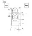
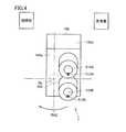
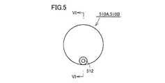
図1から図6を参照して、インジェクタヘッド1について説明する。図1は、インジェクタヘッド1を示す側面図(プライミング姿勢)、図2は、図1中のII線矢視図、図3は、インジェクタヘッド1を示す側面図(造影剤導入可能姿勢)、図4は、図3中のIV線矢視図である。また、図5は、インジェクタヘッドに装着されるシリンジの、図6中V線矢視から見た側面図、図6は、インジェクタヘッドに装着されるシリンジの、図5中VI−VI線矢視断面図である。(Injector head 1)
The
インジェクタヘッド1は回転機構を有し、支持部としての支持柱900と、回転軸ALが略水平となるように支持柱900に固定される回転部700と、回転軸ALを回転中心として回転可能にこの回転部700に固定されるインジェクタヘッド本体100と、インジェクタヘッド本体100に対して着脱可能に装着される第1シリンジ510Aおよび第2シリンジ510Bとを備える。回転部700には、ローラベアリング等が用いられる。 The
第1シリンジ510Aおよび第2シリンジ510Bのそれぞれの先端部に設けられる貫通孔512には、薬液流路切替装置600が連結されている。この薬液流路切替装置600の詳細については後述する。インジェクタヘッド本体100の側面には、タッチパネルで構成された操作用モニタ110が設けられている(図3参照)。 A chemical liquid
第1シリンジ510Aおよび第2シリンジ510Bには、図5および図6に示す形状のシリンジが用いられる。このシリンジは、先端側が閉じられ後端側にはピストン511が液密的に嵌め入れられる開口が設けられた円筒状部514と、先端側に設けられた貫通孔512と、後端側に設けられたフランジ513とを備える。 As the
ピストン511は、ピストンラバー511a、および、このピストンラバー511aに覆われるピストンコア511bを含む。ピストンコア511bには、インジェクタヘッド本体100に内蔵されたプランジャ100Pが連結される。円筒状部514は、インジェクタヘッド本体100に固定されている。 The
プランジャ100Pの前進移動および後進移動にともない、ピストン511も円筒状部514を前後方向に移動する。ピストンラバー511aは、円筒状部514の内周面に対して液密性を保ちながら移動する。 As the
本実施の形態におけるシリンジ510は、シリンジ510の中心軸線SLに対して、偏芯した位置に貫通孔512が設けられている。なお、シリンジ510の中心軸線とは、シリンジ510の中心軸をとおり先端側および後端側に延びる仮想の線を意味する。 The syringe 510 in the present embodiment is provided with a through
再び、図1から図4を参照して、第1シリンジ510Aおよび第2シリンジ510Bがインジェクタヘッド本体100に装着された状態において、回転軸ALに垂直かつ水平な方向(紙面垂直方向)から見た場合に、第1シリンジ510Aの中心軸線SLおよび第2シリンジ510Bの中心軸線SLが、回転軸ALに対して傾斜している。 Again referring to FIGS. 1 to 4, the first syringe 510 </ b> A and the second syringe 510 </ b> B are viewed from a direction perpendicular to the rotation axis AL (perpendicular to the paper surface) in a state where the first syringe 510 </ b> A and the second syringe 510 </ b> B are attached to the
回転軸ALに垂直かつ水平な方向(紙面垂直方向)から見た場合の中心軸線SLと回転軸ALとの交わる角度(α)は、5度〜30度程度であり、好ましくは7度〜25度程度、より好ましくは10度〜15度程度である。 The angle (α) between the central axis SL and the rotation axis AL when viewed from a direction perpendicular to the rotation axis AL (direction perpendicular to the paper surface) is about 5 to 30 degrees, preferably 7 to 25 degrees. It is about 10 degrees, more preferably about 10 degrees to 15 degrees.
具体的には、図1を参照して、インジェクタヘッド本体100は、略直方体形状を有し、インジェクタヘッド本体100の第1面100aに第1シリンジ510Aおよび第2シリンジ510Bが装着され、第1面100aに対向する第2面100bの上側(第3面100c側)角部領域に回転部700が固定されている。図においては、一例として、第1シリンジ510Aおよび第2シリンジ510Bに造影剤Zが満たされた状態を示している。 Specifically, referring to FIG. 1, injector head
図1および図2に示す、プライミング姿勢では、第1面100aと第2面100bとの間の上側に位置する第3面100cは、第2面100b側から第1面100a側に向けて上昇しており、また、第1面100aと第2面100bとの間の下側に位置する第4面100dも、第2面100b側から第1面100a側に向けて上昇している。 In the priming posture shown in FIGS. 1 and 2, the
また、このプライミング姿勢では、第1シリンジ510Aおよび第2シリンジ510Bのそれぞれの貫通孔512が最も上側に位置するように、第1シリンジ510Aおよび第2シリンジ510Bがインジェクタヘッド本体100に装着されている。 Further, in this priming posture, the
図3および図4に示すように、インジェクタヘッド本体100を回転軸ALを回転中心として回転(図2中の矢印RA1方向)させた造影剤導入可能姿勢では、第1面100aと第2面100bとの間の上側に位置する第4面100dは、第2面100b側から第1面100a側に向けて下降しており、また、第1面100aと第2面100bとの間の下側に位置する第4面100dも、第2面100b側から第1面100a側に向けて下降している。 As shown in FIGS. 3 and 4, in the posture in which the contrast medium can be introduced by rotating the injector head
このインジェクタヘッド1は、インジェクタヘッド本体100を、回転軸ALを回転中心として回転させることにより、第1シリンジ510Aおよび第2シリンジ510Bのそれぞれの貫通孔512側がインジェクタヘッド本体100側よりも上側の位置となることで、第1シリンジ510Aおよび第2シリンジ510Bにプライミング姿勢を与える状態(図1および図2に示す状態)と、第1シリンジ510Aおよび第2シリンジ510Bのそれぞれの貫通孔512側がインジェクタヘッド本体100側よりも下側の位置となることで、第1シリンジ510Aおよび第2シリンジ510Bに造影剤導入可能姿勢を与える状態(図3および図4に示す状態)との選択が可能である。 The
図1および図2に示すプライミング姿勢においては、回転軸ALに垂直かつ水平な方向から見た場合に、第1シリンジ510Aの中心軸線SLは、第1シリンジ510Aの貫通孔512側において、回転軸ALと交差している。図3および図4に示す造影剤導入可能姿勢においては、回転軸ALに垂直かつ水平な方向から見た場合に、第1シリンジ510Aの中心軸線SLは、第1シリンジ510Aのインジェクタヘッド本体100側において、回転軸ALと交差するように、インジェクタヘッド本体100に装着される。 In the priming posture shown in FIGS. 1 and 2, the central axis SL of the first syringe 510 </ b> A is on the side of the through-
図1および図2に示すプライミング姿勢においては、回転軸ALに垂直かつ水平な方向から見た場合に、第2シリンジ510Bの中心軸線SLは、第2シリンジ510Bのインジェクタヘッド本体100側において、回転軸ALと交差している。 In the priming posture shown in FIGS. 1 and 2, the central axis SL of the
図3および図4に示す造影剤導入可能姿勢においては、回転軸ALに垂直かつ水平な方向から見た場合に、第2シリンジ510Bの中心軸線SLは、第2シリンジ510Bの貫通孔512側において、回転軸ALと交差するように、インジェクタヘッド本体100に装着される。 3 and 4, the central axis SL of the
これにより、図1および図2に示す「プライミング姿勢」と、図3および図4に示す「造影剤導入可能姿勢」との間を、インジェクタヘッド本体100が回転移動した場合においても、第1シリンジ510Aおよび第2シリンジ510Bに連結された薬液流路切替装置600から延びる連結チューブ12は、回転軸ALの周りを移動するに止まる。 Thereby, even when the injector head
その結果、このインジェクタヘッド1に連結される連結チューブ12と他の機器との干渉を生じさせ難くなる。これにより、チューブの長さに余裕をもたせる必要が無くなる。また、技師にとって、チューブと他の機器等とが接触しないようにすべき注意の軽減を図ることも可能になる。 As a result, it becomes difficult to cause interference between the connecting
上記においては、2本のシリンジを用いたダブルシリンジ型のインジェクタヘッド1について説明したが、2本に限定されず、いずれか一方のシリンジを用いたシングルシリンジ型のインジェクタヘッドとして用いることも可能である。 In the above description, the double syringe
シリンジ510として、貫通孔512が中心軸線CLから偏芯しているシリンジを採用しているが、貫通孔512が中心軸線CL上に設けられるシリンジを採用することも可能である。 As the syringe 510, a syringe in which the through
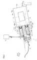
(造影剤導入流路L1000)
次に、図7を参照して、上記構成を備えるインジェクタヘッド1を用いた、患者への造影剤導入流路L1000について説明する。インジェクタヘッド本体100に装着された第1シリンジ510Aおよび第2シリンジ510Bには、薬液流路切替装置600が連結されている。この薬液流路切替装置600の詳細については後述する。(Contrast medium introduction flow path L1000)
Next, with reference to FIG. 7, a contrast medium introduction flow path L1000 for a patient using the
この造影剤導入流路L1000は、複数の患者に用いられる複数回使用セクションS1と、1人の患者に対してのみ使用する1回使用セクションS2および1回使用セクションS3とに分けることができる。 The contrast medium introduction channel L1000 can be divided into a multi-use section S1 used for a plurality of patients, a single-use section S2 used for only one patient, and a single-use section S3.
複数回使用セクションS1について説明する。図7中の点線で囲まれたインジェクタヘッド1を含む領域が複数回使用セクションS1である。複数回使用セクションS1は、薬液流路切替装置600を有する。薬液流路切替装置600には、第7チューブ15が連結され、この第7チューブ15には、造影剤バッグ16が連結されている。薬液流路切替装置600には患者側に通じる連結チューブ12が連結されている。連結チューブ12の先端には、コネクタ13が接続されている。 The multi-use section S1 will be described. A region including the
1回使用セクションS2について説明する。図7中の点線で囲まれた領域が1回使用セクションS2である。1回使用セクションS2は、一端にコネクタ14が接続され、他端にコネクタ20が接続された主チューブ17を有する。コネクタ14は、連結チューブ12のコネクタ13に接続される。 The single use section S2 will be described. A region surrounded by a dotted line in FIG. 7 is a one-time use section S2. The single use section S2 has a
主チューブ17には、T字管17tを用いて分岐チューブ17aが連結されている。分岐チューブ17aの先端には、コネクタ25が接続されている。主チューブ17および分岐チューブ17aは、造影/血圧流路切替装置800により、主チューブ17の開閉および分岐チューブ17aの開閉が制御される。 A
造影/血圧流路切替装置800は、切替弁体801、固定弁体802および固定弁体803を有し、切替弁体801が、図中の矢印RA10方向に移動可能に制御される。切替弁体801と固定弁体803とにより、主チューブ17の開閉が制御され、切替弁体801と固定弁体802とにより、分岐チューブ17aの開閉が制御される。 The contrast / blood pressure
分岐チューブ17aのコネクタ25は、生理食塩水チューブ19に設けられたコネクタ26に連結される。生理食塩水チューブ19の他端は、生理食塩水バッグ27に連結されている。生理食塩水チューブ19には、活栓820、血圧トランスジューサ300、ローラポンプ400、および、第3エアセンサAS3が設けられている。 The
1回使用セクションS3について説明する。図中の点線で囲まれた患者側の領域が1回使用セクションS3である。1回使用セクションS3は、一端にコネクタ21が接続され、他端にコネクタ23が接続されたチューブ22を有する。コネクタ21には、主チューブ17のコネクタ20が連結される。コネクタ23には、患者の血管に挿入されたカテーテルが連結される。 The single use section S3 will be described. An area on the patient side surrounded by a dotted line in the figure is a one-time use section S3. The single use section S3 includes a
インジェクタヘッド1から造影剤を患者側に導入する場合には、切替弁体801と固定弁体802とにより、分岐チューブ17aを閉鎖し、主チューブ17を開通させた状態にする。 When the contrast medium is introduced from the
患者の血圧測定は、切替弁体801と固定弁体803とにより、主チューブ17を閉鎖し、分岐チューブ17aと生理食塩水バッグ27とが連通した状態で測定する。血圧の測定には、血圧トランスジューサ300から得られる電気信号を用いる。 The blood pressure of the patient is measured in a state where the
ここで、患者の血圧測定は、上記したように切替弁体801と固定弁体803とにより主チューブ17を閉鎖し、分岐チューブ17aを開状態にして、分岐チューブ17aと生理食塩水バッグ27とを連通させた状態で行なわれる。 Here, in measuring the blood pressure of the patient, as described above, the
この時、主チューブ17のT字管17tから見て複数回使用セクションS1側の部分が、切替弁体801と固定弁体803とにより挟み込まれることで、患者の血液の複数回使用セクションS1側への侵入を阻止している。 At this time, the multiple use section S1 side portion of the
しかし、固定弁体803と切替弁体801とにより挟み込まれる主チューブ17の領域が、T字管17tから見て複数回使用セクションS1側に離れた場所に位置するために(図中の距離S)、患者の血圧がこの距離Sの分だけ、血圧トランスジューサ300によって得られる電気信号が鈍くなることが考えられる。その結果、血圧トランスジューサ300によって得られた電気信号を補正する必要が生じる場合が考えられる。 However, since the region of the
(実施の形態1:活栓流路切替装置)
そこで、図8を参照して、本実施の形態における造影/血圧流路切替装置としての活栓流路切替装置800Aについて説明する。図8は、インジェクタヘッド1に本実施の形態における活栓流路切替装置800Aを連結した場合の患者への造影剤導入流路L1000を示す図である。(Embodiment 1: Stopcock flow path switching device)
Therefore, with reference to FIG. 8, a stopcock
この活栓流路切替装置800Aは、三方活栓810を有し、この三方活栓810には、第1チューブ(第1流路)17A、第2チューブ(第2流路)17B、および、第3チューブ(第3流路)17Cのそれぞれの一端が連結されている。第1チューブ17Aは、インジェクタヘッド1側に連結され、第2チューブ17Bは、患者側に連結され、第3チューブ17Cは、血圧トランスジューサ300側に連結される。 This stopcock flow
第1チューブ17Aの他端には、コネクタ14が設けられている。第1チューブ17Aのコネクタ14は、複数回使用セクションS1に設けられる連結チューブ12のコネクタ13に接続される。 A
第2チューブ17Bの他端には、コネクタ20が設けられている。第2チューブ17Bのコネクタ20は、1回使用セクションS3に設けられるチューブ22のコネクタ21に接続される。 A
第3チューブ17Cの他端には、コネクタ25が設けられている。第3チューブ17Cのコネクタ25は、生理食塩水チューブ19に設けられたコネクタ26に接続される。第3チューブ17Cには、血圧トランスジューサ300および活栓820が設けられている。なお、血圧トランスジューサ300および活栓820は、図7で説明したように、生理食塩水チューブ19側に設けてもよい。 A
上記三方活栓810は、駆動モータを用いて流路切替コック810dを回動させることにより、第1チューブ17Aと第2チューブ17Bとを連通し、第3チューブ17Cを閉鎖して患者とインジェクタヘッドとを連結する流路造影剤導入流路を形成する状態と、第1チューブ17Aと第3チューブ17Cとを連通し、第2チューブ17Bを閉鎖して患者とトランスジューサとを連結する血圧測定流路を形成する状態との切替が可能に設けられている。 The three-
活栓流路切替装置800Aは、第1チューブ17Aの開閉を制御するクランプ機構812を有している。このクランプ機構812は、第1チューブ17Aの外側において、第1チューブ17Aを挟み込むように対向配置される固定弁体812aおよび可動弁体812bを有している。活栓流路切替装置800Aは、クランプ機構812の開閉動作を、流路切替コック810dの回動動作と連動させる切替連動機構815を有している。The stopcock flow
(切替連動機構815)
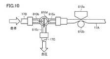
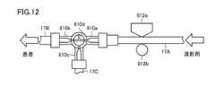
図9から図12を参照して、本実施の形態における切替連動機構815について説明する。図9は、切替連動機構815において、血圧測定流路が選択された場合の装置構成を示す模式図、図10は、切替連動機構815において血圧測定流路が選択された状態を示す図である。また、図11は、切替連動機構815において造影剤導入流路が選択された場合の装置構成を示す模式図、図12は、切替連動機構815において造影剤導入流路が選択された状態を示す図である。(Switching interlocking mechanism 815)
With reference to FIGS. 9 to 12, the switching
まず、図9を参照して、切替連動機構815の詳細構造について説明する。切替連動機構815は、回転中心C2を有する支持部813を有する。この支持部813には、支持部813から異なる方向に延びる第1リンクバー813aおよび第2リンクバー813bが設けられている。 First, the detailed structure of the switching
第1リンクバー813aの先端には可動弁体812bが取り付けられている。可動弁体812bは円柱形状を有し、その軸芯を中心にして回転可能に第1リンクバー813aに固定されている。本実施の形態において、第1リンクバー813aと第2リンクバー813bとが交差する角度は、約135度程度である。なお、この交差する角度は、装置構成に応じて適宜変更可能である。 A
第2リンクバー813bの先端には、摺動ローラ814が取り付けられている。摺動ローラ814は円柱形状を有し、その軸芯を中心にして回転可能に第2リンクバー813bに固定されている。 A sliding
また、摺動ローラ814は、常に偏芯カムローラ816の側面に当接するように付勢力Fが付与されている。たとえば、支持部813の内部にバネ等を用いた付勢手段を設けておくことで、摺動ローラ814に対して偏芯カムローラ816の側面に当接する付勢力Fを付与することができる。 Further, the sliding
三方活栓810の流路切替コック810dには、回転中心C1が同一に設けられた偏芯カムローラ816が設けられている。流路切替コック810dおよび偏芯カムローラ816は、サーボモータ等を用いた駆動装置により回転角度が制御されており、同一に回転位置制御が行なわれる。 The flow
図9に示す状態においては、摺動ローラ814は、偏芯カムローラ816の回転中心C1から最も遠ざかる位置に位置している。この偏芯カムローラ816の回転位置においては、図10に示すように、三方活栓810の流路切替コック810dは、第2ポート810bと第3ポート810cとを連結する状態となる。また、可動弁体812bは、固定弁体812aに最も近接する位置となり、第1チューブ17Aを閉鎖状態にする。 In the state shown in FIG. 9, the sliding
これにより、第2ポート810bに連結された第2チューブ17Bと第3ポート810cに連結された第3チューブ17Cとが連通し、第1チューブ17Aが、固定弁体812aと可動弁体812bとを用いたクランプ機構812により閉鎖される。その結果、患者と血圧トランスジューサ300とを連結する血圧測定流路が形成される状態が得られる。なお、血圧測定流路が形成される状態においては、第3チューブ17Cに設けられた活栓820は、第3チューブ17Cが閉状態となるようにしておく。Thus, through third communication with
なお、活栓820に替わり、ローラポンプ400を駆動させた場合に、ローラポンプ400側から患者側方向への生理食塩水の流れを許容する一方弁を設けてもよい。 Instead of the
次に、図11および図12を参照して、三方活栓810の流路切替コック810dを時計回転方向に90度回転させた場合を示す。図11に示す状態においては、摺動ローラ814は、偏芯カムローラ816の回転中心C1から最も近接する位置に位置している。 Next, with reference to FIG. 11 and FIG. 12, the case where the flow-
この偏芯カムローラ816の回転位置においては、図12に示すように、三方活栓810の流路切替コック810dは、第1ポート810aと第2ポート810bとを連結する状態となる。また、クランプ機構812の可動弁体812bは、固定弁体812aから最も遠ざかる位置となり、第1チューブ17Aを開状態にする。 At the rotational position of the
これにより、第1ポート810aに連結された第1チューブ17Aと第2ポート810bに連結された第2チューブ17Bとが連通し、第3チューブ17Cが閉鎖されることにより、患者とインジェクタヘッドとを連結する流路造影剤導入流路が形成される状態が得られる。 As a result, the
流路造影剤導入流路が形成される状態(図11および図12に示す状態)から、血圧測定流路が形成される状態(図9および図10に示す状態)に移行する場合には、流路切替コック810dを反時計回転方向に90度回転させる。 When shifting from the state where the channel contrast medium introduction channel is formed (the state shown in FIGS. 11 and 12) to the state where the blood pressure measurement channel is formed (the state shown in FIGS. 9 and 10), The flow
以上、本実施の形態における活栓流路切替装置800Aにおいては、三方活栓810を用いて、第1チューブ17Aと第2チューブ17Bとを連通し、第3チューブ17Cを閉鎖して患者とインジェクタヘッドとを連結する流路造影剤導入流路を形成する状態と、第1チューブ17Aと第3チューブ17Cとを連通し、第2チューブ17Bを閉鎖して患者とトランスジューサとを連結する血圧測定流路を形成する状態との切替を行なっている。これにより、三方活栓810を通じて患者の血圧が血圧トランスジューサに加わるため、患者の血圧測定をより正確に行なうことが可能となる。 As described above, in stopcock flow
また、活栓流路切替装置800Aにおいては、切替連動機構815を採用することで、患者とトランスジューサとを連結する血圧測定流路が形成される状態においては、リンク機構により、インジェクタヘッド側に連結される第1チューブ17Aがクランプ機構812により閉鎖される構成を採用している。これにより、患者の血圧測定時における感染物質のインジェクタヘッド側への侵入を防止することも可能としている。 In stopcock flow
なお、本実施の形態では、切替連動機構815として、図9に示したリンク機構を採用した場合について説明したが、リンク機構を用いることなく、流路切替コック810dの回転角度制御とクランプ機構812の可動弁体812bの位置制御とを、制御装置を用いて個別に行なうことも可能である。 In the present embodiment, the case where the link mechanism shown in FIG. 9 is employed as the switching
また、クランプ機構812においては、固定弁体812aと可動弁体812bとにより、第1チューブ17Aをクランプする構成を採用しているが、いずれの弁体も可動可能な弁体とすることも可能である。 Further, in the
(実施の形態2)
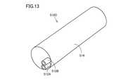
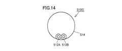
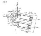
次に、図13から図16を参照して、本実施の形態におけるインジェクタヘッドに装着されるシリンジ510Cについて説明する。図13は、本実施の形態におけるシリンジの構成を示す全体斜視図、図14は、本実施の形態におけるシリンジの構成を示す側面図、図15は、関連技術における流路構成および造影剤流路切替装置の構成を示す図、図16は、本実施の形態におけるシリンジを採用した場合の流路構成および造影剤流路切替装置の構成を示す図である。(Embodiment 2)
Next, referring to FIG. 13 to FIG. 16, the
図13および図14を参照して、本実施の形態におけるシリンジ510Cの基本的構成は、図5および図6を用いて説明したシリンジ510A,510Bと同じであり、相違点は、円筒状部514の先端側に2つの貫通孔512A,512Bが、同一の側に並んで設けられている点にある。 Referring to FIGS. 13 and 14, the basic configuration of syringe 510 </ b> C in the present embodiment is the same as syringes 510 </ b> A and 510 </ b> B described using FIGS. 5 and 6, and the difference is
ここで、図15を参考にして、関連技術における流路構成および薬液流路切替装置600の構成について説明する。薬液流路切替装置600は、装置の反対側に主要機器が位置するため破線で示すべきものであるが、説明の便宜上、図15においては、実線で示すものとする。 Here, with reference to FIG. 15, the flow path configuration and the configuration of the chemical flow
まず、流路構成について説明する。インジェクタヘッド本体100には、内部に造影剤Zが充填される第1シリンジ510Aと、内部に造影剤Zが充填される第2シリンジ510Bとが装着されている。第1シリンジ510Aの内部には第1プランジャ100Paに連結する第1ピストン511Aが設けられ、第2シリンジ510Bの内部には第2プランジャ100Pbに連結する第2ピストン511B設けられている。 First, the flow path configuration will be described. The
第1シリンジ510Aには、第1チューブ10Aの一端が連結されている。第1チューブ10Aの他端は、第1T字管11Aに連結されている。第1T字管11Aには、第3チューブ111Aおよび第5チューブ112Aのそれぞれの一端が連結されている。 One end of the
第2シリンジ510Bには、第2チューブ10Bの一端が連結されている。第2チューブ10Bの他端は、第2T字管11Bに連結されている。第2T字管11Bには、第4チューブ111Bおよび第6チューブ112Bのそれぞれの一端が連結されている。 One end of the second tube 10B is connected to the
第3チューブ111Aおよび第4チューブ111Bのそれぞれの他端は、第3T字管11Cに連結されている。また、第3T字管11Cには、他端が造影剤バッグ16に連結される第7チューブ15が連結されている。 The other ends of the
第5チューブ112Aおよび第6チューブ112Bのそれぞれの他端は、第4T字管11Dに連結されている。また、第4T字管11Dには、他端がコネクタ13に連結された連結チューブ12が連結されている。 The other ends of the
連結チューブ12にはチューブ内へのエアの混入を検知する第1エアセンサAS1が設けられ、第7チューブ15にはチューブ内へのエアの混入を検知する第2エアセンサAS2が設けられている。 The
(薬液流路切替装置600)
第3チューブ111Aの開閉と第5チューブ112Aの開閉とを切り換えるための薬液流路切替装置600が設けられている。この薬液流路切替装置600は、第1流路切替機構600Aと造影/血圧流路切替機構600Bとを有している。(Chemical liquid flow path switching device 600)
A chemical
第1流路切替機構600Aは、並行に配置された第3チューブ111Aと第5チューブ112Aとを切り替えるために設けられ、造影/血圧流路切替機構600Bは、並行に配置された第4チューブ111Bと第6チューブ112Bとを切り替えるために設けられている。 The first flow
第1流路切替機構600Aは、第3チューブ111Aと第5チューブ112Aとの間に配置され、各チューブの延びる方向に対して交差する方向に移動可能に設けられる第1切替弁体603を有している。また、第1流路切替機構600Aは、各チューブを挟んで第1切替弁体603が対向する位置に、第1固定弁体601および第2固定弁体602を有している。 The first flow
同様に、造影/血圧流路切替機構600Bは、第4チューブ111Bと第6チューブ112Bとの間に配置され、各チューブの延びる方向に対して交差する方向に移動可能に設けられる第2切替弁体606を有している。また、造影/血圧流路切替機構600Bは、各チューブを挟んで第2切替弁体606が対向する位置に、第3固定弁体604および第4固定弁体605を有している。 Similarly, the contrast / blood pressure
次に、図13および図14に示した本実施の形態におけるシリンジ510C1およびシリンジ510C2を用いた場合の流路構成について、図16を参照して説明する。薬液流路切替装置600の構成は、関連技術と同じである。 Next, the flow path configuration when the syringe 510C1 and the syringe 510C2 in the present embodiment shown in FIGS. 13 and 14 are used will be described with reference to FIG. The configuration of the chemical liquid
本実施の形態におけるシリンジ510C1を用いた場合の流路構成は、第3チューブ111Aの一端がシリンジ510C1の貫通孔512Aに連結され、第5チューブ112Aの一端がシリンジ510C1の貫通孔512Bに連結されている。これにより、図15に示した流路構成と比較した場合、第1T字管11Aの使用を不要としている。 In the case of using the syringe 510C1 in the present embodiment, one end of the
同様に、本実施の形態におけるシリンジ510C2を用いた場合の流路構成は、第4チューブ111Bの一端がシリンジ510C2の貫通孔512Aに連結され、第6チューブ112Bの一端がシリンジ510C2の貫通孔512Bに連結されている。これにより、図15に示した流路構成と比較した場合、第2T字管11Bの使用を不要としている。 Similarly, in the case of using the syringe 510C2 in the present embodiment, one end of the
このように本実施の形態における2つの貫通孔512A,512Bを有するシリンジ510C1,510C2を用いた場合には、流路を分岐するT字管の使用個数を減少させることが可能となる。 As described above, when the syringes 510C1 and 510C2 having the two through
以上、本発明の実施の形態について説明したが、今回開示された実施の形態はすべての点で例示であって制限的なものではないと考えられるべきである。本発明の範囲は請求の範囲によって示され、請求の範囲と均等の意味および範囲内でのすべての変更が含まれることが意図される。 Although the embodiments of the present invention have been described above, the embodiments disclosed this time should be considered as illustrative in all points and not restrictive. The scope of the present invention is defined by the terms of the claims, and is intended to include any modifications within the scope and meaning equivalent to the terms of the claims.
1 インジェクタヘッド、10A 第1チューブ、10B 第2チューブ、11A 第1T字管、11B 第2T字管、11C 第3T字管、11D 第4T字管、12 連結チューブ、13,14,20,21,25,26, コネクタ、15 第7チューブ、16 造影剤バッグ、17 主チューブ、17A 第1チューブ(第1流路)、17B 第2チューブ(第2流路)、17C 第3チューブ(第3流路)、17a 分岐チューブ、17t T字管、19 生理食塩水チューブ、22 チューブ、27 生理食塩水バッグ、100 インジェクタヘッド本体、100Pa 第1プランジャ、100Pb 第2プランジャ、100a 第1面、100b 第2面、100c 第3面、100d 第4面、110 操作用モニタ、111A 第3チューブ、111B 第4チューブ、112A 第5チューブ、112B 第6チューブ、300 血圧トランスジューサ、400 ローラポンプ、510A,510B,510C,510C1,510C2 シリンジ、511 ピストン、511A 第1ピストン、511B 第2ピストン、511a ピストンラバー、511b ピストンコア、512,512A,512B 貫通孔、513 フランジ、514 円筒状部、600 薬液流路切替装置、600A 第1流路切替機構、600B 造影/血圧流路切替機構、601 第1固定弁体、602 第2固定弁体、603 第1切替弁体、604 第3固定弁体、605 第4固定弁体、606 第2切替弁体、700 回転部、800 造影/血圧流路切替装置、800A 活栓流路切替装置、801 切替弁体、802,803 固定弁体、810 三方活栓、810a 第1ポート、810b 第2ポート、810c 第3ポート、810d 流路切替コック、812 クランプ機構、812a 固定弁体、812b 可動弁体、813 支持部、813a 第1リンクバー、813b 第2リンクバー、814 摺動ローラ、815 切替連動機構、816 偏芯カムローラ、820 活栓、900 支持柱、1000L 造影剤導入流路、AL 回転軸、AS1 第1エアセンサ、AS2 第2エアセンサ、AS3 第3エアセンサ、C1 回転中心、C2 回転中心、P 100、S1 複数回使用セクション、S2,S3 1回使用セクション、SL 中心軸線。DESCRIPTION OF SYMBOLS 1 Injector head, 10A 1st tube, 10B 2nd tube, 11A 1st T-shaped tube, 11B 2nd T-shaped tube, 11C 3rd T-shaped tube, 11D 4th T-shaped tube, 12 connection tube, 13, 14, 20, 21 25, 26, connector, 15 seventh tube, 16 contrast medium bag, 17 main tube, 17A first tube (first flow path), 17B second tube (second flow path), 17C third tube (third flow) Path), 17a branch tube, 17t T-shaped tube, 19 physiological saline tube, 22 tube, 27 physiological saline bag, 100 injector head body, 100Pa first plunger, 100Pb second plunger, 100a first surface, 100b second Surface, 100c third surface, 100d fourth surface, 110 operation monitor, 111A third tube, 111B fourth tube , 112A fifth tube, 112B sixth tube, 300 blood pressure transducer, 400 roller pump, 510A, 510B, 510C, 510C1, 510C2 syringe, 511 piston, 511A first piston, 511B second piston, 511a piston rubber, 511b piston core , 512A, 512B, through-hole, 513 flange, 514, cylindrical part, 600 chemical liquid channel switching device, 600A first channel switching mechanism, 600B contrast / blood pressure channel switching mechanism, 601 first fixed valve body, 602 first 2 fixed valve body, 603 1st switching valve body, 604 3rd fixed valve body, 605 4th fixed valve body, 606 2nd switching valve body, 700 rotating part, 800 contrast / blood pressure flow path switching device, 800A stopcock flow path Switching device, 801 switching valve body, 802, 803 fixed valve body, 810 3 Direction stopcock, 810a 1st port, 810b 2nd port, 810c 3rd port, 810d Flow path switching cock, 812 Clamp mechanism,812a Fixed valve body, 812b Movable valve body, 813 Support part, 813a 1st link bar, 813b 1st 2 link bar, 814 sliding roller, 815 switching interlock mechanism, 816 eccentric cam roller, 820 stopcock, 900 support column, 1000L contrast agent introduction flow path, AL rotating shaft, AS1 first air sensor, AS2 second air sensor, AS3 first 3 air sensors, C1 center of rotation, C2 center of rotation, P 100, S1 multi-use section, S2, S3 single use section, SL center axis.
Claims (5)
Translated fromJapanese流路切替コック(810d)を有し、前記流路切替コック(810d)の切替により、前記患者側の流路と前記インジェクタヘッド(1)側の流路とを連結して前記造影剤導入流路を形成する状態と、前記患者側の流路と前記血圧トランスジューサ(300)側の流路とを連結して前記血圧測定流路を形成する状態との流路切替が可能に設けられた三方活栓(810)と、
前記血圧測定流路を形成する状態において、前記三方活栓(810)の前記インジェクタヘッド(1)側に連通する流路を閉鎖するクランプ機構(812)と、
を備える、活栓流路切替装置。A stopcock flow used for switching between a contrast medium introduction channel for introducing a contrast medium into a patient using the injector head (1) and a blood pressure measurement channel for measuring the blood pressure of the patient using a blood pressure transducer (300). A path switching device,
A flow path switching cock (810d), and switching the flow path switching cock (810d) connects the flow path on the patient side and the flow path on the injector head (1) side to flow the contrast medium introduction flow. Three-way provided to be able to switch between a state of forming a path and a state of forming the blood pressure measurement channel by connecting the channel on the patient side and the channel on the blood pressure transducer (300) side A stopcock (810),
A clamp mechanism (812) for closing the flow path communicating with the injector head (1) side of the three-way cock (810) in a state of forming the blood pressure measurement flow path;
A stopcock flow path switching device.
前記切替連動機構(815)は、
前記造影剤導入流路を形成する状態においては、前記可動弁体(812b)を、前記固定弁体(812a)から最も離れる位置に移動させて前記第1流路(17A)を開放し、前記血圧測定流路を形成する状態においては、前記固定弁体(812a)に最も近接する位置に移動させて前記固定弁体(812a)とともに前記第1流路(17A)を挟み込んで前記第1流路(17A)を遮蔽する、請求項2に記載の活栓流路切替装置。Said clamping mechanism (812), the outside of the first flow path (17A), the fixed valve body which is disposed opposite so as to sandwich said first flow path (17A) and(8 12 a) the movable valve body (812b )
The switching interlock mechanism (815)
In the state of forming the contrast agent introducing passage, said movable valve body (812b), is moved to open said first flow path (17A) to the farthest position from the fixed valve body (812 a) , in a state of forming the blood pressure measurement flow path, said stationary valve member (812 a) to the most adjacent said fixed valve body is moved to a position (812 a) together with the first flow path a (17A) The stopcock flow path switching device according to claim 2, wherein the first flow path (17A) is sandwiched to shield the first flow path (17A).
前記流路切替コック(810d)に設けられ、前記流路切替コック(810d)と回転中心(C1)が同一に設けられた偏芯カムローラ(816)と、
回転中心(C2)を有する支持部(813)と、
前記支持部(813)に設けられ、前記支持部(813)から異なる方向に延びる第1リンクバー(813a)および第2リンクバー(813b)と、
前記第1リンクバー(813a)の先端に設けられる前記可動弁体(812b)と、
前記第2リンクバー(813b)の先端に設けられ、常に前記偏芯カムローラ(816)の側面に当接する摺動ローラ(814)と、を備え、
前記造影剤導入流路を形成する状態においては、前記摺動ローラ(814)は、前記偏芯カムローラ(816)の前記回転中心(C1)に最も近接する位置に位置するとともに、前記可動弁体(812b)は前記固定弁体(812a)から最も離れる位置となり、
前記血圧測定流路を形成する状態においては、前記摺動ローラ(814)は、前記偏芯カムローラ(816)の前記回転中心(C1)から最も遠ざかる位置に位置するとともに、前記可動弁体(812b)は前記固定弁体(812a)に最も近接する位置となる、請求項3に記載の活栓流路切替装置。The switching interlock mechanism (815)
An eccentric cam roller (816) provided in the flow path switching cock (810d) and having the same rotation center (C1) as the flow path switching cock (810d);
A support (813) having a center of rotation (C2);
A first link bar (813a) and a second link bar (813b) provided in the support portion (813) and extending in different directions from the support portion (813);
The movable valve body (812b) provided at the tip of the first link bar (813a);
A sliding roller (814) provided at the tip of the second link bar (813b) and always in contact with a side surface of the eccentric cam roller (816),
In the state in which the contrast medium introduction flow path is formed, the sliding roller (814) is positioned closest to the rotation center (C1) of the eccentric cam roller (816), and the movable valve body (812b) becomes farthest position from the fixed valve body(8 12 a),
In the state in which the blood pressure measurement channel is formed, the sliding roller (814) is positioned farthest from the rotation center (C1) of the eccentric cam roller (816) and the movable valve body (812b). ) is the position closest to the fixed valve body (812 a), the stopcock flow switching device according to claim 3.
Applications Claiming Priority (1)
| Application Number | Priority Date | Filing Date | Title |
|---|---|---|---|
| PCT/JP2012/069435WO2014020692A1 (en) | 2012-07-31 | 2012-07-31 | Stopcock device for switching between channels |
Publications (2)
| Publication Number | Publication Date |
|---|---|
| JP5925320B2true JP5925320B2 (en) | 2016-05-25 |
| JPWO2014020692A1 JPWO2014020692A1 (en) | 2016-07-11 |
Family
ID=50027423
Family Applications (1)
| Application Number | Title | Priority Date | Filing Date |
|---|---|---|---|
| JP2014527864AActiveJP5925320B2 (en) | 2012-07-31 | 2012-07-31 | Stopcock flow path switching device |
Country Status (4)
| Country | Link |
|---|---|
| US (1) | US9901730B2 (en) |
| JP (1) | JP5925320B2 (en) |
| CN (1) | CN104507527B (en) |
| WO (1) | WO2014020692A1 (en) |
Families Citing this family (7)
| Publication number | Priority date | Publication date | Assignee | Title |
|---|---|---|---|---|
| DK2802370T3 (en)* | 2012-01-09 | 2017-03-13 | Sanofi Aventis Deutschland | PATTERN NAV WITH ACTIVE VALVE |
| EP3659573B1 (en)* | 2017-07-25 | 2023-10-04 | JMS Co., Ltd. | Liquid medicine preparation apparatus |
| CN108771771B (en)* | 2018-04-13 | 2020-06-30 | 中国人民解放军陆军军医大学第一附属医院 | Flushing and sucking device for taking breast injection material |
| CN110869069B (en)* | 2018-09-05 | 2021-04-06 | 深圳市迈威生物科技有限公司 | Disposable Components and Fluid Delivery Systems |
| JP7144464B2 (en) | 2020-01-20 | 2022-09-29 | ディーブイエックス株式会社 | Contrast injection device and injection line kit |
| JP7671767B2 (en)* | 2020-01-27 | 2025-05-02 | ベクトン・ディキンソン・アンド・カンパニー | Syringe Actuated Stopcock Smart Valve |
| WO2023242896A1 (en)* | 2022-06-13 | 2023-12-21 | スーガン株式会社 | Cock valve switching mechanism |
Family Cites Families (10)
| Publication number | Priority date | Publication date | Assignee | Title |
|---|---|---|---|---|
| JPH07100212A (en)* | 1993-10-08 | 1995-04-18 | Nemoto Kyorindo:Kk | Stopcock for medical treatment |
| JPH09108360A (en)* | 1995-10-04 | 1997-04-28 | Hiroko Umetsu | Manual contrast media injection device for blood vessel contrast |
| JP3288943B2 (en) | 1996-12-06 | 2002-06-04 | スーガン株式会社 | Medical injector head |
| JP3874484B2 (en) | 1997-03-05 | 2007-01-31 | スーガン株式会社 | Medical injector head |
| CN1105850C (en)* | 1998-06-29 | 2003-04-16 | 斯冈株式会社 | Channel Switching apparatus |
| JP3195314B2 (en)* | 1999-05-24 | 2001-08-06 | 川澄化学工業株式会社 | Contrast agent introduction set and contrast agent injection device |
| JP3809114B2 (en)* | 2001-11-05 | 2006-08-16 | スーガン株式会社 | Channel switching device and contrast medium injection tube used in the device |
| JP2004065737A (en) | 2002-08-08 | 2004-03-04 | Nemoto Kyorindo:Kk | Liquid chemical injecting apparatus |
| JPWO2008155938A1 (en)* | 2007-06-20 | 2010-08-26 | テルモ株式会社 | Multiway stopcock and liquid dosing circuit |
| EP2554212A4 (en)* | 2010-03-26 | 2014-08-20 | Terumo Corp | LIQUID DISTRIBUTION CIRCUIT |
- 2012
- 2012-07-31CNCN201280074978.1Apatent/CN104507527B/ennot_activeExpired - Fee Related
- 2012-07-31JPJP2014527864Apatent/JP5925320B2/enactiveActive
- 2012-07-31USUS14/418,942patent/US9901730B2/ennot_activeExpired - Fee Related
- 2012-07-31WOPCT/JP2012/069435patent/WO2014020692A1/enactiveApplication Filing
Also Published As
| Publication number | Publication date |
|---|---|
| WO2014020692A1 (en) | 2014-02-06 |
| CN104507527A (en) | 2015-04-08 |
| CN104507527B (en) | 2017-07-11 |
| JPWO2014020692A1 (en) | 2016-07-11 |
| US20150202425A1 (en) | 2015-07-23 |
| US9901730B2 (en) | 2018-02-27 |
Similar Documents
| Publication | Publication Date | Title |
|---|---|---|
| JP5925320B2 (en) | Stopcock flow path switching device | |
| JP5774115B2 (en) | Injector head with rotating mechanism | |
| JP5836387B2 (en) | Priming method | |
| JP4791692B2 (en) | Low pressure measuring device in high pressure environment | |
| JP5023121B2 (en) | Fluid control device for drug supply | |
| CN106137332B (en) | Ultrasound intervention sting device and piercing assembly | |
| JP4021621B2 (en) | Channel switching device | |
| CA2884094A1 (en) | Method, apparatus and system for the performance of valsalva maneuvers | |
| JP6927232B2 (en) | Flow path switching device | |
| JP5566460B2 (en) | Hand switch with valve and chemical introduction system | |
| US20160022217A1 (en) | Universal pressure transducer mounting device | |
| EP3189866B1 (en) | Status of an irrigation pump | |
| CN120754359A (en) | Indwelling needle for transcranial Doppler ultrasound imaging | |
| JPH0434407B2 (en) |
Legal Events
| Date | Code | Title | Description |
|---|---|---|---|
| A521 | Request for written amendment filed | Free format text:JAPANESE INTERMEDIATE CODE: A523 Effective date:20160303 | |
| TRDD | Decision of grant or rejection written | ||
| A01 | Written decision to grant a patent or to grant a registration (utility model) | Free format text:JAPANESE INTERMEDIATE CODE: A01 Effective date:20160405 | |
| A61 | First payment of annual fees (during grant procedure) | Free format text:JAPANESE INTERMEDIATE CODE: A61 Effective date:20160419 | |
| R150 | Certificate of patent or registration of utility model | Ref document number:5925320 Country of ref document:JP Free format text:JAPANESE INTERMEDIATE CODE: R150 | |
| R250 | Receipt of annual fees | Free format text:JAPANESE INTERMEDIATE CODE: R250 | |
| R250 | Receipt of annual fees | Free format text:JAPANESE INTERMEDIATE CODE: R250 | |
| R250 | Receipt of annual fees | Free format text:JAPANESE INTERMEDIATE CODE: R250 | |
| R250 | Receipt of annual fees | Free format text:JAPANESE INTERMEDIATE CODE: R250 | |
| R250 | Receipt of annual fees | Free format text:JAPANESE INTERMEDIATE CODE: R250 | |
| R250 | Receipt of annual fees | Free format text:JAPANESE INTERMEDIATE CODE: R250 | |
| R250 | Receipt of annual fees | Free format text:JAPANESE INTERMEDIATE CODE: R250 |