JP5925109B2 - Image processing apparatus, control method thereof, and control program - Google Patents
Image processing apparatus, control method thereof, and control programDownload PDFInfo
- Publication number
- JP5925109B2 JP5925109B2JP2012248450AJP2012248450AJP5925109B2JP 5925109 B2JP5925109 B2JP 5925109B2JP 2012248450 AJP2012248450 AJP 2012248450AJP 2012248450 AJP2012248450 AJP 2012248450AJP 5925109 B2JP5925109 B2JP 5925109B2
- Authority
- JP
- Japan
- Prior art keywords
- image
- distance
- subject
- parallax
- amount
- Prior art date
- Legal status (The legal status is an assumption and is not a legal conclusion. Google has not performed a legal analysis and makes no representation as to the accuracy of the status listed.)
- Active
Links
Images


Landscapes
- Testing, Inspecting, Measuring Of Stereoscopic Televisions And Televisions (AREA)
- Image Analysis (AREA)
- Image Processing (AREA)
Description
Translated fromJapanese本発明は、撮像装置によって2つ以上の異なる視点から被写体を撮像し、当該撮像装置から被写体までの距離に応じて画像を生成する画像処理装置、その制御方法、および制御プログラムに関する。 The present invention relates to an image processing apparatus that captures an image of a subject from two or more different viewpoints using an imaging device and generates an image according to the distance from the imaging device to the subject, a control method thereof, and a control program.
従来、2つの異なる視点から被写体を撮像して、撮像装置から被写体までの距離に応じて画像(以下距離画像と呼ぶ)を生成することが行われている。 Conventionally, a subject is imaged from two different viewpoints, and an image (hereinafter referred to as a distance image) is generated according to the distance from the imaging device to the subject.
例えば、2台の撮像装置によって左右の異なる視点から被写体を撮像して、距離画像を生成する手法として、非特許文献1に記載の手法がある。 For example, there is a method described in
非特許文献1では、まず、左右の異なる視点で撮影された2つの画像について、撮像レンズの歪み補正を行う。そして、左右の異なる視点間においてカメラの角度と距離とを調整するため、左右の画像を写像する(ステレオ平行化)。続いて、左右のカメラのビューにおいて同一の特徴を求めて、視差画像を生成する(ステレオ対応点探索)。次に、左右のカメラの幾何学的な位置情報に応じて、視差画像を距離画像に変換する(3D再投影)。 In
ところが、非特許文献1に記載の手法では、1台のカメラを撮影者が手動で視点移動させて視差のある2つの画像を撮像する場合においては、左右の視点の幾何学的な位置をカメラが調整してその位置情報を特定することができない。よって、視差画像を距離画像に変換することができないという問題点がある。 However, in the method described in
さらに、非特許文献1に記載の手法では、左右のカメラの幾何学的な位置情報を取得する際、所謂ステレオキャリブレーションを用いている。このため、非特許文献1においては、位置情報を得るためチェスボードチャートのような形状が既知であるキャリブレーションパターンを撮影する必要がある。このため、ロボットアーム用のカメラおよびやセキュリティカメラなど、その用途が限定されてしまう。 Furthermore, in the method described in
従って、本発明の第1の目的は、左右の視点の幾何学的な位置を調整できない場合においても距離画像を生成することができる画像処理装置、その制御方法、および制御プログラムを提供することにある。 Accordingly, a first object of the present invention is to provide an image processing apparatus capable of generating a distance image even when the geometric positions of the left and right viewpoints cannot be adjusted, a control method thereof, and a control program. is there.
本発明の第2の目的は、その用途が限定されることが少ない画像処理装置、その制御方法、および制御プログラムを提供することにある。 A second object of the present invention is to provide an image processing apparatus, its control method, and control program whose use is rarely limited.
上記の目的を達成するため、本発明による画像処理装置は、撮像手段によって互いに異なる視点から特定の被写体を撮像して得られた複数の画像に応じて、前記撮像手段から前記特定の被写体までの距離に応じた距離画像を生成する画像処理装置であって、前記複数の画像の視差量に応じた視差画像を得る視差画像取得手段と、前記撮像手段から前記特定の被写体までの距離を示す距離情報を求める距離情報取得手段と、前記視差量および前記距離情報に応じて、前記視点うちの一つの投影中心に対する他の視点の投影中心の移動量である並進移動量を求める並進移動量取得手段と、前記視差画像と前記並進移動量とに応じて前記距離画像を生成する距離画像取得手段と、を有することを特徴とする。 In order to achieve the above object, an image processing apparatus according to the present invention provides a plurality of images obtained by imaging a specific subject from different viewpoints by the imaging unit, from the imaging unit to the specific subject. An image processing apparatus that generates a distance image according to a distance, a parallax image acquisition unit that obtains a parallax image according to a parallax amount of the plurality of images, and a distance that indicates a distance from the imaging unit to the specific subject Distance information acquisition means for obtaining information, and translational movement amount acquisition means for obtaining a translational movement amount that is a movement amount of the projection center of another viewpoint with respect to one projection center of the viewpoints according to the parallax amount and the distance information And distance image acquisition means for generating the distance image in accordance with the parallax image and the translational movement amount.
本発明による制御方法は、撮像手段によって互いに異なる視点から特定の被写体を撮像して得られた複数の画像に応じて、前記撮像手段から前記特定の被写体までの距離に応じた距離画像を生成する画像処理装置の制御方法であって、前記複数の画像の視差量に応じた視差画像を得る視差画像取得ステップと、前記撮像手段から前記特定の被写体までの距離を示す距離情報を求める距離情報取得ステップと、前記視差量および前記距離情報に応じて、前記視点うちの一つの投影中心に対する他の視点の投影中心の移動量である並進移動量を求める並進移動量取得ステップと、前記視差画像と前記並進移動量とに応じて前記距離画像を生成する距離画像取得ステップと、を有することを特徴とする。 The control method according to the present invention generates a distance image corresponding to a distance from the imaging unit to the specific subject according to a plurality of images obtained by imaging the specific subject from different viewpoints by the imaging unit. A method for controlling an image processing apparatus, wherein a parallax image obtaining step for obtaining a parallax image corresponding to a parallax amount of the plurality of images, and distance information obtaining for obtaining distance information indicating a distance from the imaging unit to the specific subject A translational movement amount obtaining step for obtaining a translational movement amount that is a movement amount of a projection center of another viewpoint with respect to one projection center of the viewpoints according to the parallax amount and the distance information; and the parallax image; A distance image acquisition step of generating the distance image according to the translational movement amount.
本発明による制御プログラムは、撮像手段によって互いに異なる視点から特定の被写体を撮像して得られた複数の画像に応じて、前記撮像手段から前記特定の被写体までの距離に応じた距離画像を生成する画像処理装置で用いられる制御プログラムであって、前記画像処理装置が備えるコンピュータに、前記複数の画像の視差量に応じた視差画像を得る視差画像取得ステップと、前記撮像手段から前記特定の被写体までの距離を示す距離情報を求める距離情報取得ステップと、前記視差量および前記距離情報に応じて、前記視点うちの一つの投影中心に対する他の視点の投影中心の移動量である並進移動量を求める並進移動量取得ステップと、前記視差画像と前記並進移動量とに応じて前記距離画像を生成する距離画像取得ステップと、を実行させることを特徴とする制御プログラム。 The control program according to the present invention generates a distance image corresponding to the distance from the imaging unit to the specific subject according to a plurality of images obtained by imaging the specific subject from different viewpoints by the imaging unit. A control program used in the image processing device, the computer included in the image processing device obtaining a parallax image according to the parallax amount of the plurality of images, and from the imaging unit to the specific subject A distance information acquisition step for obtaining distance information indicating a distance of a distance, and a translational movement amount that is a movement amount of a projection center of another viewpoint with respect to one projection center of the viewpoints according to the parallax amount and the distance information. A translational movement amount acquisition step, and a distance image acquisition step of generating the distance image according to the parallax image and the translational movement amount. A control program for causing the.
本発明によれば、左右の視点の幾何学的な位置を撮像手段で調整できない場合であっても、用途を限定することなく距離画像を生成することができる。 According to the present invention, even when the geometric positions of the left and right viewpoints cannot be adjusted by the imaging unit, it is possible to generate a distance image without limiting the application.
以下、本発明の実施の形態による画像処理装置の一例について図面を参照して説明する。 Hereinafter, an example of an image processing apparatus according to an embodiment of the present invention will be described with reference to the drawings.
[第1の実施形態]
図1は、本発明の第1の実施形態による画像処理装置が用いられた撮像装置の一例についてその構成を示すブロック図である。[First Embodiment]
FIG. 1 is a block diagram showing the configuration of an example of an imaging apparatus using the image processing apparatus according to the first embodiment of the present invention.
図示の撮像装置は、例えば、デジタルカメラ(以下単にカメラと呼ぶ)であり、カメラは結像光学系101を有している。そして、この結像光学系101は撮影レンズおよび絞りなどを備えており、フォーカス調節および焦点距離調整を行う。 The illustrated imaging device is, for example, a digital camera (hereinafter simply referred to as a camera), and the camera has an imaging
結像光学系101の後段には、CCDなどの撮像素子102が配置され、結像光学系101から入射した光学像(被写体像)は撮像素子102に結像する。撮像素子102は光学像に応じた電気信号(アナログ画像信号)を出力する。このアナログ画像信号はA/D変換回路103によってデジタル画像信号に変換されて、信号処理回路104およびAF評価値取得回路108に与えられる。 An
信号処理回路104はデジタル画像信号に対して所定の信号処理を施して画像データとする。そして、この画像データはメモリ制御回路105によってメモリ(例えば、DRAM)106に書き込まれる。また、メモリ制御回路105はメモリ106に書き込まれた画像データを読み出して、表示部109に画像データに応じた画像を表示するとともに、必要に応じて当該画像データを信号処理回路104に送る。 The
AF評価値取得回路108は、デジタル画像信号に応じて、結像光学系101のオート・フォーカス(AF)調整用のAF評価値を生成する。そして、このAF評価値はメモリ制御回路105を介してシステム制御回路107に与えられ、システム制御回路107はAF評価値に基づいて、結像光学系101のAF制御を行う。なお、システム制御回路107はカメラ全体の制御を司る。 The AF evaluation
システム制御回路107には操作部110が接続され、ユーザは操作部110を操作して各種指示をシステム制御回路110に与える。また、システム制御回路107は表示部109にカメラに関する各種カメラ情報を表示する。 An
結像光学系101のAF制御を行う際には、既知の山登りコントラストAFが用いられる。つまり、デジタル画像信号に応じた画面において、AF測距枠で規定された領域におけるコントラスト(つまり、AF評価値)が極大となるようにAF制御が行われる。さらに、フォーカス調整後の結像光学系101の位置(光軸に沿った位置)に応じて、AF測距枠の合焦被写体までの距離が求められる。 When performing AF control of the imaging
図2は、図1に示す信号処理回路104の構成を説明するためのブロック図である。 FIG. 2 is a block diagram for explaining the configuration of the
図2において、左画像201および右画像202は、撮影の結果得られた画像データであり、メモリ106に格納されている。ここでは、ユーザが被写体をフレーミングしている際においても、撮像素子102は、システム制御回路107の制御下で連続的に被写体を撮像しており、これによって、フレーミングによる視点移動を用いて左画像201および右画像202を得る。 In FIG. 2, a
カメラから被写体までの距離に応じて画像(以下距離画像と呼ぶ)を生成する際には、システム制御回路107の制御下でメモリ制御回路105によってメモリ106から左画像201および右画像202が読み出されて、信号処理回路104に送られる。 When an image (hereinafter referred to as a distance image) is generated according to the distance from the camera to the subject, the
図示のように、信号処理回路104は、ホモグラフィ推定回路203、逆写像処理回路204および205、ステレオ対応点探索回路206、および3次元(3D)再投影回路207を備えている。そして、左画像201はホモグラフィ推定回路203および逆写像回路204に与えられ、右画像202はホモグラフィ推定回路203および逆写像回路205に与えられる。 As illustrated, the
ホモグラフィ推定回路203は左画像201および右画像202を受けて、ステレオ平行化のためのホモグラフィを推定するホモグラフィ推定処理を行う。ホモグラフィ推定処理では、結像光学系101による歪みが補正された座標系を用いる必要がある。ここで用いられる歪み補正は非特許文献1に記載の補正手法と同様であり、座標変換式は次の式(1)で表される。 The

ここで、(x,y)は歪んだ点の元の位置であり、(xcorrected,ycorrected)は補正の結果得られる位置である。さらに、rは歪んだ点の元の位置のレンズ中心からの距離であり、k1、k2、およびk3は結像光学系101で用いられるレンズの形状から決定される歪み補正係数である。Here, (x, y) is the original position of the distorted point, and (xcorrected , ycorrected ) is the position obtained as a result of correction. Further, r is the distance from the lens center at the original position of the distorted point, and k1, k2, and k3 are distortion correction coefficients determined from the shape of the lens used in the imaging
ここでは、歪み補正において半径方向歪みのみを補正するものとしたが、半径方向の歪み補正に限定されるものではなく、例えば、円周方向の歪みも補正するようにしてもよい。 Here, only the distortion in the radial direction is corrected in the distortion correction, but is not limited to the distortion correction in the radial direction. For example, the distortion in the circumferential direction may be corrected.
また、ステレオ平行化のためのホモグラフィ推定の手法は非特許文献1に記載の手法と同様である。 A homography estimation method for stereo parallelization is the same as the method described in
図3は、左右の視点が形成する撮像系をピンホールモデルで示す図である。 FIG. 3 is a diagram illustrating an imaging system formed by the left and right viewpoints using a pinhole model.
図3において、OlおよびOrはそれぞれ左右の視点の投影中心位置、Pは被写体位置、plおよびprはそれぞれ左右の視点の投影平面に投影される被写体の結像位置を示す。また、elおよびerはそれぞれ左右の視点におけるエピポールを示し、そして、pl,elおよびpr,erはそれぞれ左右の視点におけるエピポーラ線を示す。In FIG. 3, Ol and Or are the projection center positions of the left and right viewpoints, P is the subject position, and pl andpr are the imaging positions of the objects projected on the projection planes of the left and right viewpoints, respectively. Also shows epipole ine l ande r are perspective left and right,and, p l, showing the epipolar lines ine l andp r,e r is the viewpoint of the left and right.
エピポーラ拘束によって、1つの画像内の特徴点が与えられると、もう一つの画像内で対応する点は対応するエピポーラ線上に存在する。このため、ステレオ対応点探索はエピポーラ線に沿って対応点探索することになる。そして、2つの画像においてエピポーラ線を平行にして対応点の高さを合わせると、水平方向の1次元における対応点探索となるので、2次元のものよりも計算量が大幅に軽減され、さらに結果の信頼度も高い。2つの画像でエピポーラ線を平行にして対応点の高さを合わせる座標変換がステレオ平行化と呼ばれる。 When an epipolar constraint gives a feature point in one image, the corresponding point in the other image is on the corresponding epipolar line. For this reason, the stereo corresponding point search involves searching for the corresponding points along the epipolar line. Then, if the epipolar lines are parallel in the two images and the heights of the corresponding points are adjusted, the corresponding point search in the horizontal direction is performed, so the calculation amount is greatly reduced compared to the two-dimensional one, and the result High reliability. A coordinate transformation in which epipolar lines are parallel in two images and the heights of corresponding points are matched is called stereo parallelization.
ステレオ平行を行う際には次のステップが実行される。 The following steps are performed when performing stereo parallelism.
(2−1)2つの画像で8点以上の特徴点の対応を求める。 (2-1) Correspondence between eight or more feature points in two images is obtained.
(2−2)8点以上の特徴点の対応から基礎行列Fを求める。 (2-2) A basic matrix F is obtained from the correspondence of eight or more feature points.
(2−3)基礎行列Fからエピポールelおよびerを求める。(2-3) determining the epipolee l ande r from the fundamental matrix F.
(2−4)エピポールerから右画像のステレオ平行化のためのホモグラフィHrを推定する。(2-4) for estimating the homographyH r for stereo collimation of the right image from the epipolee r.
(2−5)特徴点の対応、ホモグラフィHr、およびエピポールelから左画像のステレオ平行化のためのホモグラフィHlを推定する。(2-5) corresponding feature points to estimate the homographyH l for stereo collimation of the left image from the homographyH r, and epipolee l.
(2−1)の処理においては、2つの画像間でブロックマッチング手法による2次元の対応点探索を行って、必要な特徴点の対応を求める。画素単位で対応点探索するステレオ対応点探索とは異なり、画像一面内で最低8点の対応を求めればよいので、2次元であっても計算量が少なく結果の信頼度にも大きな影響はない。ブロックマッチング手法の詳細については、後述するステレオ対応点探索と同様であるが、ステレオ対応点探索のブロックマッチング手法は1次元方向のみの探索なので、ここではその探索範囲を2次元方向に拡張したブロックマッチング手法を用いる。 In the process of (2-1), a two-dimensional corresponding point search is performed between two images by a block matching method to obtain a necessary feature point correspondence. Unlike stereo corresponding point search, which searches for corresponding points in pixel units, it is only necessary to obtain a correspondence of at least 8 points in one image plane. Therefore, even in two dimensions, the calculation amount is small and the reliability of the result is not greatly affected. . The details of the block matching method are the same as those of the stereo corresponding point search described later. However, since the block matching method of the stereo corresponding point search is a search only in the one-dimensional direction, a block in which the search range is expanded in the two-dimensional direction here. Use a matching technique.
(2−2)の処理においては、8点の特徴点の対応から3×3行列の基礎行列Fを求める。また、特徴点の座標は上記の式(1)で歪み補正されたものを用いる。式(2)は一般にエピポーラ方程式と呼ばれている方程式である。 In the process of (2-2), a basic matrix F of 3 × 3 matrix is obtained from the correspondence of the eight feature points. Further, the coordinates of the feature points are those corrected for distortion by the above equation (1). Equation (2) is an equation generally called an epipolar equation.
式(2)において、Eは3×3行列の基本行列である。また、3×3行列のカメラ内部行列Mを用いると、一般に、式(3)によって3次元物理座標pを投影平面の2次元ピクセル座標qに変換できる。 In Equation (2), E is a basic matrix of 3 × 3 matrix. In addition, when the camera internal matrix M of 3 × 3 matrix is used, generally, the three-dimensional physical coordinate p can be converted into the two-dimensional pixel coordinate q on the projection plane by Expression (3).
また、カメラ内部行列Mを用いると、一般に式(4)によって基本行列Eを基礎行列Fに変換できる。 Further, when the camera internal matrix M is used, the basic matrix E can be converted into the basic matrix F in general by the equation (4).
式(2)から式(4)を用いると、基礎行列Fに関して、式(5)の方程式が導かれる。 When Expressions (2) to (4) are used, the equation of Expression (5) is derived for the basic matrix F.
基礎行列Fは3×3行列で、かつスカラの自由度を有するので、9個の行列要素のうちの8個が変数となる。よって、式(5)に左右画像のqlおよびqrの対応を8点代入すれば、単なる連立1次方程式となり、この連立1次方程式を解くことで基礎行列Fを求めることができる。Since the basic matrix F is a 3 × 3 matrix and has a degree of freedom of scalars, eight of the nine matrix elements are variables. Therefore, by substituting 8 points for the correspondence between ql and qr of the left and right images into Equation (5), a simple simultaneous linear equation is obtained, and the basic matrix F can be obtained by solving this simultaneous linear equation.
本発明の第1の実施形態では、基礎行列Fを求めるために左右画像のqlおよびqrの対応を8点用いているが、本発明はこれに限定されるものではなく、例えば、非特許文献1で記載されているように8点以上の対応を用いた最小二乗法によって基礎行列Fを推定するようにしてもよい。In the first embodiment of the present invention, eight points of correspondence between ql and qr of the left and right images are used to obtain the basic matrix F. However, the present invention is not limited to this, for example, non- As described in
(2−3)の処理においては、基礎行列Fからエピポールelおよびerを求める。基礎行列Fとエピポールelおよびerとの関係は一般に式(6)および(7)で示される。そして、式(6)および(7)に求めた基礎行列Fを代入することでエピポールelおよびerを求めることができる。(2-3) In the process of obtaining the epipolee l ande r from the fundamental matrix F. The relationship between the basic matrix F and the epipoles e1 and er is generallyexpressed by equations (6) and (7). Then, it is possible to obtain the epipole el and er by substituting fundamental matrix F obtained in equation (6) and (7).
(2−4)の処理においては、エピポールerからホモグラフィHrを推定する。(2-4) In the process, estimating the homographyH r from epipolee r.
図4は、ホモグラフィHlおよびHrの写像手順を説明するための図である。そして、図4(a)は右画像の投影平面におけるオブジェクトの結像イメージ(網掛けの三角形)およびエピポールerのピクセル座標(xe,ye)を示す図であり、図4(b)は図4(a)について回転行列Rを適用したピクセル座標系を示す図である。また、図4(c)は図4(b)についてホモグラフィGを適用したピクセル座標系を示す図である。FIG. 4 is a diagram for explaining the mapping procedure of the homography Hl and Hr . Then, a diagram illustrating the FIGS. 4 (a) object imaging image in the projection plane of the right image (shaded triangles) and epipolee r pixel coordinates(x e,y e), FIG. 4 (b) These are the figures which show the pixel coordinate system which applied the rotation matrix R about Fig.4 (a). FIG. 4C is a diagram showing a pixel coordinate system to which the homography G is applied to FIG.
まず、エピポールerをx軸上の(k,0)に写像する回転行列Rを、式(8)によって求める。First, the rotation matrix R that maps epipolee r in (k, 0) on the x-axis, determined by equation (8).
式(8)をエピポールerに適用すると、式(9)が得られる。Applying equation (8) to the epipolee r, equation (9) is obtained.
次に、x軸上に写像されたエピポール(k,0)を無限遠点(±∞,0)に写像するホモグラフィGを、式(10)によって求める。 Next, the homography G that maps the epipole (k, 0) mapped on the x-axis to the point at infinity (± ∞, 0) is obtained by Expression (10).
このようなホモグラフィは、全てのエピポーラ線をx軸に対して平行な直線に写像する。従って、図4(c)におけるエピポーラ線はx軸に対して平行な直線に写像される。 Such homography maps all epipolar lines to straight lines parallel to the x-axis. Therefore, the epipolar line in FIG. 4C is mapped to a straight line parallel to the x axis.
式(8)〜式(10)を用いると、ホモグラフィHrは式(11)で示される。Using the equations (8) to (10), the homographyHr is represented by the equation (11).
(2−5)の処理において、特徴点の対応、ホモグラフィHr、およびエピポールelから左画像のステレオ平行化のためのホモグラフィHlを推定する。このホモグラフィHlは、左画像の全てのエピポーラ線をx軸に対して平行な直線に写像して、左右画像の対応するエピポーラ線の高さを揃える。(2-5) In the processing of the corresponding feature points to estimate the homography Hl for stereo collimation of the homography Hr, and the left image from the epipole el. The homography Hl is all epipolar lines of the left image and mapping a straight line parallel to the x axis, align the heights of the corresponding epipolar lines of the left and right images.
左画像の全てのエピポーラ線をx軸に対して平行な直線に写像する際には、(2−4)の処理で説明した手順と同様の手順が用いられる。また、同様の手順で左画像について得られた行列を、G’およびR’とする。 When mapping all the epipolar lines in the left image to a straight line parallel to the x-axis, the same procedure as that described in the process (2-4) is used. Further, the matrices obtained for the left image in the same procedure are denoted as G ′ and R ′.
左右画像の対応するエピポーラ線の高さを揃える際には、左右画像間に存在する特徴点の対応において特徴点間距離の総和が最小になるようなホモグラフィKを推定すればよい。 When aligning the heights of the corresponding epipolar lines in the left and right images, a homography K that minimizes the sum of the distances between the feature points in the correspondence of the feature points existing between the left and right images may be estimated.
つまり、推定したホモグラフィHlは式(12)で示される。That is, the estimated homography Hl is expressed by the equation (12).
さらに、ホモグラフィKを推定するためには、式(13)が用いられる。 Furthermore, in order to estimate the homography K, equation (13) is used.
なお、式(13)において、dd(ql,qr)は、2つのピクセル座標間の距離自乗和を示している。また、特徴点の対応(qli,qri)については、(2−1)の処理で求めたものを用いればよい。In equation (13), dd (ql , qr ) represents the sum of squared distances between two pixel coordinates. As for the corresponding feature point(q l i, q r i ), it may be used those obtained in the process (2-1).
逆写像処理回路204および205は、ステレオ平行化のためのホモグラフィを用いて、それぞれ左画像201および右画像202をステレオ平行化する。ここで、ステレオ平行化のための逆写像処理の手法は非特許文献1に記載の手法と同様である。 The inverse
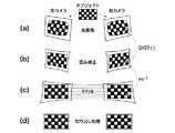
図5は、本発明の第1の実施形態において、撮像された画像(生画像)をステレオ平行化された左右画像に写像する手順を説明するための図である。そして、図5(a)は生画像を示す図であり、図5(b)は歪み補正後の画像を示す図である。また、図5(c)は平行化処理後の画像を示す図であり、図5(d)は切り出し処理後の画像を示す図である。 FIG. 5 is a diagram for describing a procedure for mapping a captured image (raw image) to a stereo-parallelized left and right image in the first embodiment of the present invention. FIG. 5A shows a raw image, and FIG. 5B shows an image after distortion correction. FIG. 5C shows an image after the parallelization process, and FIG. 5D shows an image after the clipping process.
ここでは、ステレオ平行化された画像内の各整数座標(図5(c))に対して、歪んでいない画像(図5(b))内の座標を求めて、これら座標を用いて生画像(図5(a))内の小数点座標を参照する逆写像処理を行う。つまり、この小数点座標を用いて生画像内で画素補間処理を行って、ステレオ平行化画像(図5(c))内での画素値を求める。 Here, for each integer coordinate in the stereo-parallelized image (FIG. 5C), the coordinates in the undistorted image (FIG. 5B) are obtained, and the raw image is obtained using these coordinates. Inverse mapping processing is performed with reference to the decimal point coordinates in FIG. That is, pixel interpolation processing is performed in the raw image using the decimal point coordinates, and pixel values in the stereo parallelized image (FIG. 5C) are obtained.
なお、図中のDIST()は、式(1)に示す(xcorrected,ycorrected)から(x,y)を求める式(1)の逆変換処理である。Note that DIST () in the figure is an inverse conversion process of Expression (1) forobtaining (x, y) from (xcorrected , ycorrected ) shown in Expression (1).
逆写像処理回路204および205の出力はステレオ対応点探索回路206に与えられる。ステレオ対応点探索回路206はステレオ平行化された左画像201および右画像202から視差画像208を生成する。なお、ステレオ対応点探索回路206におけるステレオ対応点探索は非特許文献1に記載の手法と同様である。 The outputs of the inverse
図6は、本発明の第1の実施形態におけるステレオ対応点探索で用いられるブロックマッチング手法を説明するための図である。 FIG. 6 is a diagram for explaining a block matching method used in the stereo correspondence point search in the first embodiment of the present invention.
ブロックマッチングは、差分絶対値和(SAD)ウィンドウを行方向にスライドすることによって行われる。これによって、左の画像内おける各特徴点に対して、右の画像において対応する行から最もよくマッチするものを探す。左右画像はステレオ平行化されて各行がエピポーラ線になっており、右の画像内でマッチングする箇所は左の画像内の同一の行にあるため、探索方向は行方向だけに限定することができる。 Block matching is performed by sliding the sum of absolute differences (SAD) window in the row direction. As a result, for each feature point in the left image, the best match is searched from the corresponding row in the right image. The left and right images are stereo-parallelized and each row is an epipolar line, and the matching location in the right image is in the same row in the left image, so the search direction can be limited to the row direction only. .
左の画像内のある特徴点のx座標xlに対して、対応する右の画像内の対応点のx座標xrまでの距離d=(xl−xr)が対応する視差量となる。For the x coordinate xl of a certain feature point in the left image, the distance d = (xl −xr ) to the x coordinate xr of the corresponding point in the corresponding right image is the corresponding amount of parallax. .
ステレオ対応点探索回路206で生成された視差画像208は、3D再投影回路207に与えられる。3D再投影回路207は視差画像208から距離画像209を生成する。なお、ここで用いられる3D再投影は非特許文献1に記載の手法と同様である。 The
三角測量の手法によって、距離Zと視差量dとの関係は一般に式(14)で表される。 By the triangulation method, the relationship between the distance Z and the parallax amount d is generally expressed by Expression (14).
ここで、fは撮像系の焦点距離、Tは左右2つの視点の投影中心の距離である。 Here, f is the focal length of the imaging system, and T is the distance between the projection centers of the two left and right viewpoints.
3D再投影回路207で生成された距離画像209は、メモリ制御回路105を介してメモリ106に書き込まれる。 The
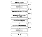
図7は、図1に示すカメラで行われる距離画像生成制御を説明するためのフローチャートである。 FIG. 7 is a flowchart for explaining distance image generation control performed by the camera shown in FIG.
距離画像生成が開始されると、前述したようにして、システム制御回路107の制御下で、ステレオ対応点探索回路206は、逆写像処理回路204および205でステレオ平行化された左右画像を処理して視差画像を生成する(ステップS101)。 When the distance image generation is started, as described above, the stereo correspondence
図8は、図1に示すカメラによる視点移動を説明するための図である。 FIG. 8 is a diagram for explaining viewpoint movement by the camera shown in FIG. 1.
図8において、撮像素子102は投影平面の配置されており、撮像素子102の後側に左画像を撮像した時の投影中心301および右画像を撮影した時の投影中心302がある。また、図8における左右視点の投影中心および投影平面の位置はステレオ平行化後のものであって、X軸方向は並進移動の方向、Z軸方向は距離画像における距離の方向である。 In FIG. 8, the
図8においては、被写体(A)303、被写体(B)304、および被写体(C)305が存在するとともに、背景被写体306が存在する。なお、fは結像光学系101の焦点距離、Tは左視点の投影中心に対する右視点の投影中心の並進移動量、ZA、ZB、およびZCはそれぞれX軸から被写体302、被写体304、および被写体305までの距離である。In FIG. 8, a subject (A) 303, a subject (B) 304, and a subject (C) 305 exist, and a
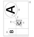
図9は、図1に示すカメラにおいて左視点および右視点で撮像されたステレオ平行化画像を説明するための図である。 FIG. 9 is a diagram for explaining a stereo parallelized image captured from the left viewpoint and the right viewpoint in the camera shown in FIG.
図9において、実線は左画像における被写体輪郭、破線は右画像における被写体輪郭を表している。dA、dB、およびdCはそれぞれ被写体(A)303、被写体(B)304、および被写体(C)305の視差量である。被写体(A)303が最も距離が近いので視差量が最も大きく、被写体の視差量は被写体(C)305および被写体(B)304の順で小さくなる。In FIG. 9, the solid line represents the subject outline in the left image, and the broken line represents the subject outline in the right image. dA , dB , and dC are parallax amounts of the subject (A) 303, the subject (B) 304, and the subject (C) 305, respectively. Since the subject (A) 303 is the shortest distance, the amount of parallax is the largest, and the amount of parallax of the subject decreases in the order of subject (C) 305 and subject (B) 304.
図10は、図1に示すカメラで生成された視差画像を示す図である。 FIG. 10 is a diagram showing a parallax image generated by the camera shown in FIG.
図10に示す例では、被写体(A)303はその視差量が50μmであり、被写体(B)304はその視差量が10μmである。また、被写体(C)305はその視差量が20μmであり、背景被写体306はその視差量が2μmである。 In the example shown in FIG. 10, the subject (A) 303 has a parallax amount of 50 μm, and the subject (B) 304 has a parallax amount of 10 μm. The subject (C) 305 has a parallax amount of 20 μm, and the
システム制御回路107の制御下で、3D再投影回路207は視差画像から視差量信頼度が高い被写体を選択被写体(つまり、特定の被写体)として選択する(ステップS102)。ここでは、視差量信頼度は被写体の視差量に応じて判定されるものとする。つまり、視差量閾値をdthとした際、d>dthを満たす視差量dを有する被写体が被写体信頼度の高い被写体と判定される。例えば、dth=40μmとすると、図10から被写体(A)303が視差量信頼度の高い被写体として選択されることになる。Under the control of the
続いて、システム制御回路107の制御下で、3D再投影回路207は選択された被写体までの距離を取得する(ステップS103)。 Subsequently, under the control of the
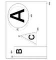
図11は、図1に示すカメラにおいて投影平面上におけるAF測距枠の位置を説明するための図である。 FIG. 11 is a diagram for explaining the position of the AF distance measurement frame on the projection plane in the camera shown in FIG.
図11において、被写体(A)303が測距の対象であるので、システム制御回路107は被写体(A)303に合わせてAF測距枠401を設定し、山登りコントラストAFによって被写体(A)303までの距離ZAを求める。In FIG. 11, since the subject (A) 303 is the object of distance measurement, the
次に、システム制御回路107の制御下で、3D再投影回路207は投影中心の並進移動量を取得する(ステップS104)。前述の式(14)から、並進移動量は、T=(ZAdA/f)となる。また、視差量の検出誤差をΔd、並進移動量の検出誤差をΔTとすると、検出誤差ΔTは、次の式(15)で表される。Next, under the control of the
最後に、システム制御回路107の制御下で、3D再投影回路207は視差画像について画素毎に式(14)を適用して、距離画像208を生成する(ステップS105)。そして、システム制御回路107は距離画像生成処理を終了する。 Finally, under the control of the
このように、本発明の第1の実施形態では、左右の視点の幾何学的な位置をカメラで調整できない場合であっても、用途を限定することなく距離画像を生成することができる。また、視差量dが大きい被写体、つまり、距離Zがカメラに近い被写体から並進移動量Tを検出するようにしたので、式(15)から容易に理解できるように、並進移動量の検出誤差ΔTを小さくすることができる。 As described above, in the first embodiment of the present invention, even when the geometric positions of the left and right viewpoints cannot be adjusted by the camera, the distance image can be generated without limiting the application. Further, since the translational movement amount T is detected from a subject having a large parallax amount d, that is, a subject whose distance Z is close to the camera, the translational movement amount detection error ΔT can be easily understood from the equation (15). Can be reduced.
[第2の実施形態]
続いて、本発明の第2の実施形態によるカメラの一例について説明する。なお、第2の実施形態によるカメラの構成は、図1および図2に示すカメラと同様であるので、説明を省略する。[Second Embodiment]
Next, an example of a camera according to the second embodiment of the present invention will be described. The configuration of the camera according to the second embodiment is the same as that of the camera shown in FIG. 1 and FIG.
図12は、本発明の第2の実施形態によるカメラおける距離画像の生成を説明するためのフローチャートである。なお、図12において、図7に示すフローチャートと同一のステップについては、同一の参照符号を付して説明を省略する。 FIG. 12 is a flowchart for explaining generation of a distance image in the camera according to the second embodiment of the present invention. In FIG. 12, the same steps as those in the flowchart shown in FIG. 7 are denoted by the same reference numerals, and the description thereof is omitted.
図7で説明したようにして視差画像が生成された後、システム制御回路107は、AF測距枠によって指定された被写体までの距離を取得する(ステップS202)。ユーザがAF測距枠によって被写体を指定する際には、ユーザは表示部109に表示された撮像画像を確認しつつ操作部110を操作してAF測距枠を移動する。そして、ユーザ所望の被写体にAF測距枠を位置づけて操作部110によって被写体を指定する。 After the parallax image is generated as described with reference to FIG. 7, the
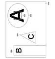
図13は、本発明の第2の実施形態によるカメラにおいて投影平面上におけるAF測距枠の位置を説明するための図である。 FIG. 13 is a diagram for explaining the position of the AF distance measurement frame on the projection plane in the camera according to the second embodiment of the present invention.
図13において、ユーザは被写体(B)304にAF測距枠401を指定されているので、ここでは、被写体(B)304が測距の対象となる。そして、システム制御回路107は山登りコントラストAFによって被写体(B)304までの距離ZBを求める。In FIG. 13, since the user has designated the AF
続いて、システム制御回路107の制御下で、ステップS104において3D再投影回路207は投影中心の並進移動量を取得する。前述の式(14)から並進移動量は、T=(ZBdB/f)となる。Subsequently, under the control of the
最後に、システム制御回路107の制御下で、ステップS105において3D再投影回路207は視差画像について画素毎に式(14)を適用して、距離画像208を生成する。そして、システム制御回路107は距離画像生成処理を終了する。 Finally, under the control of the
このように、本発明の第2の実施形態では、左右の視点の幾何学的な位置をカメラで調整できない場合であっても、用途を限定することなく距離画像を生成することができる。また、距離画像を生成する際、ユーザ所望の被写体にフォーカス位置を合わせることができる。 As described above, in the second embodiment of the present invention, even when the geometric positions of the left and right viewpoints cannot be adjusted by the camera, a distance image can be generated without limiting the application. Further, when generating the distance image, the focus position can be adjusted to the subject desired by the user.
[第3の実施形態]
続いて、本発明の第3の実施形態によるカメラの一例について説明する。なお、第3の実施形態によるカメラの構成は、図1および図2に示すカメラと同様であるので、説明を省略する。[Third Embodiment]
Next, an example of a camera according to the third embodiment of the present invention will be described. The configuration of the camera according to the third embodiment is the same as that of the camera shown in FIG. 1 and FIG.
図14は、本発明の第3の実施形態によるカメラおける距離画像の生成を説明するためのフローチャートである。なお、図14において、図7に示すフローチャートと同一のステップについては、同一の参照符号を付して説明を省略する。 FIG. 14 is a flowchart for explaining generation of a distance image in the camera according to the third embodiment of the present invention. In FIG. 14, the same steps as those in the flowchart shown in FIG. 7 are denoted by the same reference numerals, and description thereof is omitted.
図7で説明したようにして、ステップS102において、視差画像から視差量信頼度が高い被写体が選択される。なお、第3の実施形態では、dth=15μmとする。よって、ここでは、図10に示す例においては、被写体(A)303および被写体(C)305が視差量信頼度の高い被写体として選択されることになる。As described with reference to FIG. 7, in step S <b> 102, a subject with high parallax amount reliability is selected from the parallax image. In the third embodiment, dth = 15 μm. Therefore, here, in the example shown in FIG. 10, the subject (A) 303 and the subject (C) 305 are selected as subjects with high parallax amount reliability.
次に、システム制御回路107の制御下で、3D再投影回路207は表示重要度が高い被写体を選択する(ステップS303)。ここでは、画像中心からの2次元距離が近い被写体ほど重要度が高いものとする。 Next, under the control of the
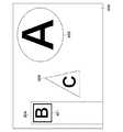
図15は、本発明の第3の実施形態によるカメラにおいて投影平面上におけるAF測距枠の位置を説明するための図である。 FIG. 15 is a diagram for explaining the position of the AF distance measurement frame on the projection plane in the camera according to the third embodiment of the present invention.
図15において、画像中心から被写体(A)303までの距離はRAであり、画像中心から被写体(C)305までの距離はRCである。ここでは、RA>RCであるので、3D再投影回路207は被写体(C)305の方が被写体(A)303よりも表示重要度が高いと判定して、被写体(C)305を選択することになる。そして、システム制御回路107は被写体(C)305に合わせてAF測距枠401を設定し、ステップS103で山登りコントラストAFによって被写体(C)305までの距離ZCを求める。In FIG. 15, the distance from the image center to the subject (A) 303 isRA , and the distance from the image center to the subject (C) 305 isRC . Here, since RA > RC , the
その後、図7で説明したステップS104およびS105の処理を行った後、システム制御回路107は距離画像生成処理を終了する。なお、第3の実施形態では、前述の式(14)から、並進移動量はT=(ZCdC/f)となる。Thereafter, after performing the processes of steps S104 and S105 described in FIG. 7, the
このように、本発明の第3の実施形態では、左右の視点の幾何学的な位置をカメラで調整できない場合であっても、用途を限定することなく距離画像を生成することができる。また、視差量dが大きい被写体、つまり、距離Zがカメラに近い被写体から並進移動量Tを検出するようにしたので、並進移動量の検出誤差ΔTを小さくすることができる。さらに、距離画像を生成する際、表示重要度に応じてフォーカスが行われるので、表示に関して品位を保つことができる。 As described above, in the third embodiment of the present invention, even when the geometric positions of the left and right viewpoints cannot be adjusted by the camera, the distance image can be generated without limiting the application. Further, since the translational movement amount T is detected from a subject having a large amount of parallax d, that is, a subject whose distance Z is close to the camera, the translational movement amount detection error ΔT can be reduced. Furthermore, since the focus is performed according to the display importance when the distance image is generated, the display quality can be maintained.
[第4の実施形態]
次に、本発明の第4の実施形態によるカメラの一例について説明する。なお、第4の実施形態によるカメラの構成は、図1および図2に示すカメラと同様であるので、説明を省略する。[Fourth Embodiment]
Next, an example of a camera according to the fourth embodiment of the present invention will be described. The configuration of the camera according to the fourth embodiment is the same as that of the camera shown in FIGS.
図16は、本発明の第4の実施形態によるカメラおける距離画像の生成を説明するためのフローチャートである。 FIG. 16 is a flowchart for explaining generation of a distance image in the camera according to the fourth embodiment of the present invention.
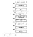
距離画像生成が開始されると、システム制御回路107は、電子ビューファインダ表示中でいるか否かを判定する(ステップS401)。ここでは、ユーザが被写体をフレーミングする目的で撮像画像を連続フレーム表示させることを電子ビューファインダと呼ぶ。ユーザは操作部110を操作して電子ビューファインダの表示又は非表示を選択する。 When the distance image generation is started, the
電子ビューファインダが表示中でないと(ステップS401において、NO)、システム制御回路107は距離優先モードに移行して、距離優先モードに応じた処理を実行する(ステップS402)。そして、システム制御回路107は距離画像生成処理を終了する。ここで、距離優先モードに応じた処理とは第1の実施形態で説明した距離画像生成に係る処理をいう。 If the electronic viewfinder is not being displayed (NO in step S401), the
一方、電子ビューファインダが表示中であると(ステップS401において、YES)、システム制御回路107はユーザがAF測距枠の位置を指示しているか否かを判定する(ステップS403)。ユーザによるAF測距枠の指示がなければ(ステップS403において、NO)、システム制御回路107は距離表示優先モードに移行して、距離表示優先モードに応じた処理を実行する(ステップS404)。そして、システム制御回路107は距離画像生成処理を終了する。ここで、距離表示優先モードに応じた処理とは第3の実施形態で説明した距離画像生成に係る処理をいう。 On the other hand, if the electronic viewfinder is being displayed (YES in step S401), the
ユーザによるAF測距枠の指示があると(ステップS403において、YES)、システム制御回路107は表示優先モードに移行して、表示優先モードに応じた処理を実行する(ステップS405)。そして、システム制御回路107は距離画像生成処理を終了する。ここで、表示優先モードに応じた処理とは第2の実施形態で説明した距離画像生成に係る処理をいう。 When the user has instructed an AF distance measurement frame (YES in step S403), the
このように、本発明の第4の実施形態では、電子ビューファインダが表示されているか否かにに応じて、距離画像の生成を変更することができる。つまり、電子ビューファインダが表示されていない場合には、距離画像の精度を高くすることができ、電子ビューファインダが表示されかつユーザ所望の被写体にフォーカスを合わせる際には、フォーカス位置に影響がないように距離画像を生成することができる。さらに、電子ビューファインダが表示されかつフォーカスが自動的に調整される際には、距離画像の精度を高くしつつ表示の品位を保つことができる。 Thus, in the fourth embodiment of the present invention, the generation of the distance image can be changed according to whether or not the electronic viewfinder is displayed. That is, when the electronic viewfinder is not displayed, the accuracy of the distance image can be increased, and the focus position is not affected when the electronic viewfinder is displayed and when focusing on a user-desired subject. Thus, a distance image can be generated. Furthermore, when the electronic viewfinder is displayed and the focus is automatically adjusted, the display quality can be maintained while increasing the accuracy of the distance image.
[第5の実施形態]
続いて、本発明の第5の実施形態によるカメラの一例について説明する。なお、第5の実施形態によるカメラの構成は、図1および図2に示すカメラと同様であるので、説明を省略する。[Fifth Embodiment]
Next, an example of a camera according to the fifth embodiment of the present invention will be described. The configuration of the camera according to the fifth embodiment is the same as that of the camera shown in FIGS.
図17は、本発明の第5の実施形態によるカメラおける距離画像の生成を説明するためのフローチャートである。なお、図17において、図16に示すフローチャートと同一のステップについては、同一の参照符号を付して説明を省略する。 FIG. 17 is a flowchart for explaining generation of a distance image in the camera according to the fifth embodiment of the present invention. In FIG. 17, the same steps as those in the flowchart shown in FIG. 16 are denoted by the same reference numerals, and the description thereof is omitted.
距離画像の生成が開始されると、まず、ステップS402において、距離優先モードに応じた処理が行われる。続いて、システム制御回路107の制御下で、3D再投影回路207は視差画像において視差量信頼度が高い被写体が選択されたか否かを判定する(ステップS502)。 When the generation of the distance image is started, first, in step S402, processing according to the distance priority mode is performed. Subsequently, under the control of the
いま、視差量閾値dthが55μmであるとすると、図10に示す例では、いずれの被写体も視差量信頼度が高くないと判定されることになる。視差量信頼度が高い被写体が選択されないと(ステップS502において、NO)、システム制御回路107は結像光学系101の焦点距離を調整して長くする(焦点距離を望遠側に調整する)。つまり、システム制御回路107は視差量信頼度が十分高くなるように焦点距離を調整する(ステップS503)。そして、システム制御回路107はステップS402の処理に戻る。Now, assuming that the parallax amount threshold dth is 55 μm, in the example shown in FIG. 10, it is determined that none of the subjects has high parallax amount reliability. If a subject with high parallax amount reliability is not selected (NO in step S502), the
例えば、図10に示す例では、焦点距離を1.2倍に調整すると、AF測距枠内にある被写体(A)303の視差量が1.2倍の60μmに調整されることになる。この場合、焦点距離を調整した影響によってピントが若干ずれてしまうが、焦点距離を調整する際には、その範囲は各被写体像における錯乱円の大きさが許容錯乱円径を超えない範囲とする。 For example, in the example shown in FIG. 10, when the focal length is adjusted to 1.2 times, the parallax amount of the subject (A) 303 within the AF distance measurement frame is adjusted to 60 μm, which is 1.2 times. In this case, the focus is slightly shifted due to the effect of adjusting the focal length, but when adjusting the focal length, the range is set so that the size of the circle of confusion in each subject image does not exceed the allowable circle of confusion. .
一方、視差量信頼度が高い被写体が選択されると(ステップS502において、YES)、システム制御回路107は距離画像の生成処理を終了する。 On the other hand, when a subject with a high degree of parallax reliability is selected (YES in step S502), the
このように、本発明の第5の実施形態では、距離優先モードによる処理の際、常に視差量信頼度が高い被写体に合わせて距離画像を生成することができる。 As described above, in the fifth embodiment of the present invention, it is possible to always generate a distance image in accordance with a subject having a high degree of parallax reliability when processing in the distance priority mode.
[第6の実施形態]
次に、本発明の第5の実施形態によるカメラの一例について説明する。なお、第5の実施形態によるカメラの構成は、図1および図2に示すカメラと同様であるので、説明を省略する。また、ここでは、時間的に連続する複数のフレーム画像について距離画像を生成する連続フレーム処理について説明する。[Sixth Embodiment]
Next, an example of a camera according to the fifth embodiment of the present invention will be described. The configuration of the camera according to the fifth embodiment is the same as that of the camera shown in FIGS. Here, a continuous frame process for generating a distance image for a plurality of temporally continuous frame images will be described.
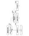
図18は、本発明の第5の実施形態によるカメラで行われる連続フレーム処理を説明するためのフローチャートである。なお、ここでは、複数のフレーム画像を撮影する際には、フレーム(1)、フレーム(2)、フレーム(3)、・・・の順で撮像が行われる。 FIG. 18 is a flowchart for explaining continuous frame processing performed by the camera according to the fifth embodiment of the present invention. Here, when a plurality of frame images are captured, imaging is performed in the order of frame (1), frame (2), frame (3),.
連続フレーム処理が開始されると、システム制御回路107の制御下で、距離画像生成処理が行われて(ステップS601)、少なくとも1つの距離画像が生成される(S601)。この距離画像生成処理は、第1の実施形態から第4の実施形態のいずれかによる処理であり、ここでは、ステップS601の処理による投影中心の並進移動量を取得する対象となる被写体までの距離Zが連続フレーム処理で用いられる。 When the continuous frame processing is started, distance image generation processing is performed under the control of the system control circuit 107 (step S601), and at least one distance image is generated (S601). This distance image generation process is a process according to any one of the first to fourth embodiments, and here, the distance to the subject that is the target of acquiring the translation amount of the projection center by the process of step S601. Z is used in continuous frame processing.
続いて、システム制御回路107はカウント数N=1(Nは1以上の整数)を設定する(ステップS602)。そして、システム制御回路107はカウント数Nが予め定められた最大数MAX_NUM以下であるか否かを判定する(ステップS603)。N>MAX_NUMであると(ステップS603において、NO)、システム制御回路107は連続フレーム処理を終了する。 Subsequently, the
一方、N≦MAX_NUMであれば(ステップS603において、NO)、システム制御回路107の制御下で、前述したように、信号処理回路104は時間的に連続する第Nの画像(つまり、フレーム(N))と第(N+1)の画像(つまり、フレーム(N+1))に応じて視差画像を生成する(ステップS604)。そして、システム制御回路107の制御下で、信号処理回路104は投影中心の並進移動量を取得する対象となる被写体を選択する(ステップS605)。 On the other hand, if N ≦ MAX_NUM (NO in step S603), the
続いて、信号処理回路104は、前述の式(14)を用いて、ステップS605で選択した被写体の視差量dと被写体距離Zとに応じて、投影中心の並進移動量を求める(ステップS606)。そして、信号処理回路104はフレーム(N)とフレーム(N+1)に応じた距離画像を生成する(ステップS607)。 Subsequently, the
なお、視差画像の生成、並進移動量を求める被写体の選択、並進移動量の算出、および、距離画像生成に係る処理は、前述の第1の実施形態〜第4の実施形態で説明したいずれかの手法が用いられる。 The processing related to the generation of the parallax image, the selection of the subject for obtaining the translational movement amount, the calculation of the translational movement amount, and the distance image generation is any of those described in the first to fourth embodiments. The method is used.
続いて、システム制御回路107は、カウント数N=N+1として(ステップS608)、ステップS603の処理に戻る。 Subsequently, the
前述したように、カウント数Nが最大数MAX_NUMを超えると、投影中心の並進移動量を求める対象である被写体が移動して被写体距離Zが変化することがある。このため、カウント数Nが最大数MAX_NUMを超えると、システム制御回路107は連続フレーム処理を終了する。 As described above, when the count number N exceeds the maximum number MAX_NUM, the subject that is the target for obtaining the translational movement amount of the projection center may move and the subject distance Z may change. For this reason, when the count number N exceeds the maximum number MAX_NUM, the
例えば、許容する距離Zの精度が10cm、想定する被写体移動速度が10cm/秒、フレームレートが60フレーム/秒である場合には、60フレームで距離Zの許容精度の10cmに達するので、最大数MAX_NUMは60とする。 For example, if the accuracy of the allowable distance Z is 10 cm, the assumed moving speed of the subject is 10 cm / second, and the frame rate is 60 frames / second, the allowable number of distance Z reaches 10 cm in 60 frames. MAX_NUM is set to 60.
よって、続けて連続フレーム処理によって距離画像を生成する際には、ステップS601から処理をやり直すことになる。 Therefore, when a distance image is continuously generated by continuous frame processing, the processing is repeated from step S601.
このように、本発明の第6の実施形態では、一連のフレーム処理において直前の処理で参照したフレーム画像のうちの一つを次のフレームでも参照するので、撮像のフレームレートと同一のレートで距離画像が生成されることになって、距離画像の時間分解能を高くすることができる。 As described above, in the sixth embodiment of the present invention, one of the frame images referred to in the immediately preceding process in the series of frame processes is also referred to in the next frame. Therefore, at the same rate as the imaging frame rate. Since the distance image is generated, the time resolution of the distance image can be increased.
上述の説明から明らかなように、図1に示す例においては、システム制御回路107および信号処理回路104が視差画像取得手段、距離情報取得手段、並進移動量取得手段、および距離画像取得手段として機能する。また、システム制御回路107は被写体選択手段として機能し、システム制御回路107および操作部110はモード選択手段として機能する。そして、システム制御回路107は焦点距離調整手段、視差量調整手段、および制御手段として機能する。 As is apparent from the above description, in the example shown in FIG. 1, the
なお、図1において、少なくとも信号処理回路104、メモリ制御回路105、システム制御回路107、AF評価値取得回路108、および操作部110は画像処理装置を構成する。また、結像光学系、撮像素子102、A/D変換回路、およびシステム制御回路107が撮像手段を構成する。 In FIG. 1, at least the
以上、本発明について実施の形態に基づいて説明したが、本発明は、これらの実施の形態に限定されるものではなく、この発明の要旨を逸脱しない範囲の様々な形態も本発明に含まれる。 As mentioned above, although this invention was demonstrated based on embodiment, this invention is not limited to these embodiment, Various forms of the range which does not deviate from the summary of this invention are also contained in this invention. .
例えば、上記の実施の形態の機能を制御方法として、この制御方法を画像処理装置に実行させるようにすればよい。また、上述の実施の形態の機能を有するプログラムを制御プログラムとして、当該制御プログラムを画像処理装置が備えるコンピュータに実行させるようにしてもよい。なお、制御プログラムは、例えば、コンピュータに読み取り可能な記録媒体に記録される。 For example, the function of the above embodiment may be used as a control method, and this control method may be executed by the image processing apparatus. In addition, a program having the functions of the above-described embodiments may be used as a control program, and the control program may be executed by a computer included in the image processing apparatus. The control program is recorded on a computer-readable recording medium, for example.
上記の制御方法および制御プログラムの各々は、少なくとも視差画像取得ステップ、距離情報取得ステップ、並進移動量取得ステップ、および距離画像取得ステップを有している。 Each of the control method and the control program has at least a parallax image acquisition step, a distance information acquisition step, a translational movement amount acquisition step, and a distance image acquisition step.
また、本発明は、以下の処理を実行することによっても実現される。つまり、上述した実施形態の機能を実現するソフトウェア(プログラム)を、ネットワーク又は各種の記録媒体を介してシステム或いは装置に供給し、そのシステム或いは装置のコンピュータ(またはCPUやMPUなど)がプログラムを読み出して実行する処理である。 The present invention can also be realized by executing the following processing. That is, software (program) that realizes the functions of the above-described embodiments is supplied to a system or apparatus via a network or various recording media, and the computer (or CPU, MPU, etc.) of the system or apparatus reads the program. To be executed.
101 結像光学系
102 撮像素子
103 A/D変換回路
104 信号処理回路
105 メモリ制御回路
106 メモリ
107 システム制御回路
108 AF評価値取得回路
109 表示部
110 操作部DESCRIPTION OF
Claims (10)
Translated fromJapanese前記複数の画像の視差量に応じた視差画像を得る視差画像取得手段と、
前記撮像手段から前記特定の被写体までの距離を示す距離情報を求める距離情報取得手段と、
前記視差量および前記距離情報に応じて、前記視点うちの一つの投影中心に対する他の視点の投影中心の移動量である並進移動量を求める並進移動量取得手段と、
前記視差画像と前記並進移動量とに応じて前記距離画像を生成する距離画像取得手段と、
を有することを特徴とする画像処理装置。An image processing apparatus that generates a distance image according to a distance from the imaging unit to the specific subject according to a plurality of images obtained by imaging the specific subject from different viewpoints by the imaging unit,
Parallax image acquisition means for obtaining parallax images according to the parallax amounts of the plurality of images;
Distance information acquisition means for obtaining distance information indicating a distance from the imaging means to the specific subject;
A translational movement amount obtaining means for obtaining a translational movement amount that is a movement amount of a projection center of another viewpoint with respect to one projection center of the viewpoints according to the parallax amount and the distance information;
Distance image acquisition means for generating the distance image according to the parallax image and the translational movement amount;
An image processing apparatus comprising:
前記距離優先モードが選択されると、前記特定の被写体として前記視差画像において前記視差量が所定の閾値より高い被写体を選択し、前記表示優先モードが選択されると、前記特定の被写体としてピントを合わせた被写体を選択し、前記距離表示優先モードが選択されると、前記視差画像において前記視差量が所定の閾値より高い被写体からピントを合わせる被写体を選択被写体として選択して当該選択被写体を前記特定の被写体とする被写体選択手段とを有することを特徴とする請求項1又は2に記載の画像処理装置。Mode selection means for selecting one mode from at least two modes among the distance priority mode, the display priority mode, and the distance display priority mode;
When the distance priority mode is selected, a subject whose parallax amount is higher than a predetermined threshold in the parallax image is selected as the specific subject, and when the display priority mode is selected, the specific subject is focused. When a combined subject is selected and the distance display priority mode is selected, a subject to be focused is selected as a selected subject from subjects whose parallax amount is higher than a predetermined threshold in the parallax image, and the selected subject is specified. The image processing apparatus according to claim 1, further comprising: a subject selection unit that sets the subject as a subject.
前記特定の被写体に係る視差量が所定の閾値よりも小さいと、前記焦点距離調整手段を制御して前記焦点距離を望遠側に調整し前記特定の被写体に係る視差量を前記閾値より大きくする視差量調整手段とを有することを特徴とすることを特徴する請求項1〜6のいずれか1項に記載の画像処理装置。A focal length adjusting means for adjusting a focal length in the imaging means;
When the amount of parallax related to the specific subject is smaller than a predetermined threshold, the parallax for controlling the focal length adjusting means to adjust the focal length to the telephoto side and making the amount of parallax related to the specific subject larger than the threshold The image processing apparatus according to claim 1, further comprising an amount adjustment unit.
第Nの画像と第(N+1)の画像(Nは1以上の整数)とに応じて、前記視差画像取得手段、前記距離情報取得手段、前記並進移動量取得手段、および前記距離画像取得手段を制御して連続的に前記距離画像を求める制御手段を有することを特徴とする請求項1〜7のいずれか1項に記載の画像処理装置。Obtaining the plurality of images continuously by the imaging means;
According to the Nth image and the (N + 1) th image (N is an integer equal to or greater than 1), the parallax image acquisition means, the distance information acquisition means, the translational movement amount acquisition means, and the distance image acquisition means The image processing apparatus according to claim 1, further comprising a control unit configured to control and obtain the distance image continuously.
前記複数の画像の視差量に応じた視差画像を得る視差画像取得ステップと、
前記撮像手段から前記特定の被写体までの距離を示す距離情報を求める距離情報取得ステップと、
前記視差量および前記距離情報に応じて、前記視点うちの一つの投影中心に対する他の視点の投影中心の移動量である並進移動量を求める並進移動量取得ステップと、
前記視差画像と前記並進移動量とに応じて前記距離画像を生成する距離画像取得ステップと、
を有することを特徴とする制御方法。A control method of an image processing apparatus that generates a distance image according to a distance from the imaging unit to the specific subject according to a plurality of images obtained by imaging a specific subject from different viewpoints by the imaging unit. There,
A parallax image obtaining step for obtaining a parallax image corresponding to the parallax amount of the plurality of images;
A distance information acquisition step for obtaining distance information indicating a distance from the imaging means to the specific subject;
A translational movement amount obtaining step for obtaining a translational movement amount that is a movement amount of a projection center of another viewpoint with respect to one projection center of the viewpoints according to the parallax amount and the distance information;
A distance image acquisition step of generating the distance image according to the parallax image and the translational movement amount;
A control method characterized by comprising:
前記画像処理装置が備えるコンピュータに、
前記複数の画像の視差量に応じた視差画像を得る視差画像取得ステップと、
前記撮像手段から前記特定の被写体までの距離を示す距離情報を求める距離情報取得ステップと、
前記視差量および前記距離情報に応じて、前記視点うちの一つの投影中心に対する他の視点の投影中心の移動量である並進移動量を求める並進移動量取得ステップと、
前記視差画像と前記並進移動量とに応じて前記距離画像を生成する距離画像取得ステップと、
を実行させることを特徴とする制御プログラム。Control used in an image processing apparatus that generates a distance image according to a distance from the imaging unit to the specific subject according to a plurality of images obtained by imaging the specific subject from different viewpoints by the imaging unit A program,
In the computer provided in the image processing apparatus,
A parallax image obtaining step for obtaining a parallax image corresponding to the parallax amount of the plurality of images;
A distance information acquisition step for obtaining distance information indicating a distance from the imaging means to the specific subject;
A translational movement amount obtaining step for obtaining a translational movement amount that is a movement amount of a projection center of another viewpoint with respect to one projection center of the viewpoints according to the parallax amount and the distance information;
A distance image acquisition step of generating the distance image according to the parallax image and the translational movement amount;
A control program characterized by causing
Priority Applications (1)
| Application Number | Priority Date | Filing Date | Title |
|---|---|---|---|
| JP2012248450AJP5925109B2 (en) | 2012-11-12 | 2012-11-12 | Image processing apparatus, control method thereof, and control program |
Applications Claiming Priority (1)
| Application Number | Priority Date | Filing Date | Title |
|---|---|---|---|
| JP2012248450AJP5925109B2 (en) | 2012-11-12 | 2012-11-12 | Image processing apparatus, control method thereof, and control program |
Publications (2)
| Publication Number | Publication Date |
|---|---|
| JP2014096761A JP2014096761A (en) | 2014-05-22 |
| JP5925109B2true JP5925109B2 (en) | 2016-05-25 |
Family
ID=50939490
Family Applications (1)
| Application Number | Title | Priority Date | Filing Date |
|---|---|---|---|
| JP2012248450AActiveJP5925109B2 (en) | 2012-11-12 | 2012-11-12 | Image processing apparatus, control method thereof, and control program |
Country Status (1)
| Country | Link |
|---|---|
| JP (1) | JP5925109B2 (en) |
Families Citing this family (3)
| Publication number | Priority date | Publication date | Assignee | Title |
|---|---|---|---|---|
| WO2016042779A1 (en)* | 2014-09-18 | 2016-03-24 | 日本電気株式会社 | Triangulation device, triangulation method, and recording medium recording program therefor |
| JP6694234B2 (en)* | 2015-01-23 | 2020-05-13 | シャープ株式会社 | Distance measuring device |
| CN113556607A (en)* | 2021-07-07 | 2021-10-26 | 深圳创维-Rgb电子有限公司 | Watching distance reminding method, device, equipment and storage medium of smart television |
Family Cites Families (4)
| Publication number | Priority date | Publication date | Assignee | Title |
|---|---|---|---|---|
| JP2000048204A (en)* | 1998-07-31 | 2000-02-18 | Ines Corp | How to create an actual size solid model |
| JP2005031044A (en)* | 2003-07-11 | 2005-02-03 | Olympus Corp | Three-dimensional error measuring device |
| US8269820B2 (en)* | 2006-11-02 | 2012-09-18 | Konica Minolta Holdings, Inc. | Wide-angle image acquiring method and wide-angle stereo camera device |
| JP2008216127A (en)* | 2007-03-06 | 2008-09-18 | Konica Minolta Holdings Inc | Distance image generation device, distance image generation method, and program |
- 2012
- 2012-11-12JPJP2012248450Apatent/JP5925109B2/enactiveActive
Also Published As
| Publication number | Publication date |
|---|---|
| JP2014096761A (en) | 2014-05-22 |
Similar Documents
| Publication | Publication Date | Title |
|---|---|---|
| KR102143456B1 (en) | Depth information acquisition method and apparatus, and image collection device | |
| JP4852591B2 (en) | Stereoscopic image processing apparatus, method, recording medium, and stereoscopic imaging apparatus | |
| JP5472328B2 (en) | Stereo camera | |
| US8144974B2 (en) | Image processing apparatus, method, and program | |
| JP6436783B2 (en) | Image processing apparatus, imaging apparatus, image processing method, program, and storage medium | |
| JP6071257B2 (en) | Image processing apparatus, control method therefor, and program | |
| JP2013211827A (en) | Image processing method, device and program | |
| JPWO2011010438A1 (en) | Parallax detection device, distance measuring device, and parallax detection method | |
| WO2011125937A1 (en) | Calibration data selection device, method of selection, selection program, and three dimensional position measuring device | |
| CN108260360B (en) | Scene depth calculation method and device and terminal | |
| JP2010239564A (en) | Imaging apparatus, imaging control method, and program | |
| JP7489253B2 (en) | Depth map generating device and program thereof, and depth map generating system | |
| JP2019062340A (en) | Image blurring correction apparatus and control method | |
| JP5925109B2 (en) | Image processing apparatus, control method thereof, and control program | |
| JP6732440B2 (en) | Image processing apparatus, image processing method, and program thereof | |
| JP6602412B2 (en) | Information processing apparatus and method, information processing system, and program. | |
| CN111292380A (en) | Image processing method and device | |
| JP6648916B2 (en) | Imaging device | |
| JP2019083407A (en) | Image blur correction device and control method therefor, and imaging device | |
| JP6292785B2 (en) | Image processing apparatus, image processing method, and program | |
| JP6566765B2 (en) | Imaging device | |
| JP2009237652A (en) | Image processing apparatus and method, and program | |
| JP2012022716A (en) | Apparatus, method and program for processing three-dimensional image, and three-dimensional imaging apparatus | |
| JP7324639B2 (en) | Subject position estimation device, focus assist device, and programs thereof | |
| KR101283825B1 (en) | 3-d auto-convergence camera |
Legal Events
| Date | Code | Title | Description |
|---|---|---|---|
| A621 | Written request for application examination | Free format text:JAPANESE INTERMEDIATE CODE: A621 Effective date:20150612 | |
| A977 | Report on retrieval | Free format text:JAPANESE INTERMEDIATE CODE: A971007 Effective date:20160304 | |
| TRDD | Decision of grant or rejection written | ||
| A01 | Written decision to grant a patent or to grant a registration (utility model) | Free format text:JAPANESE INTERMEDIATE CODE: A01 Effective date:20160322 | |
| A61 | First payment of annual fees (during grant procedure) | Free format text:JAPANESE INTERMEDIATE CODE: A61 Effective date:20160419 | |
| R151 | Written notification of patent or utility model registration | Ref document number:5925109 Country of ref document:JP Free format text:JAPANESE INTERMEDIATE CODE: R151 |