JP5921981B2 - Video display device and video display method - Google Patents
Video display device and video display methodDownload PDFInfo
- Publication number
- JP5921981B2 JP5921981B2JP2012164311AJP2012164311AJP5921981B2JP 5921981 B2JP5921981 B2JP 5921981B2JP 2012164311 AJP2012164311 AJP 2012164311AJP 2012164311 AJP2012164311 AJP 2012164311AJP 5921981 B2JP5921981 B2JP 5921981B2
- Authority
- JP
- Japan
- Prior art keywords
- hand
- user
- operation area
- area
- image
- Prior art date
- Legal status (The legal status is an assumption and is not a legal conclusion. Google has not performed a legal analysis and makes no representation as to the accuracy of the status listed.)
- Active
Links
Images


Landscapes
- Position Input By Displaying (AREA)
- User Interface Of Digital Computer (AREA)
Description
Translated fromJapanese本発明は、ユーザのジェスチャー操作を画像認識して、操作に対する応答を表示させる映像表示装置および映像表示方法に関する。 The present invention relates to an image display apparatus and an image display method for recognizing a user's gesture operation and displaying a response to the operation.
従来、TVやレコーダといった映像装置、あるいは、PCなどの情報処理機器に対して、ユーザは、キーボードやマウスなどのポインティングデバイスを使ってデータ入力や指示入力をしたり、リモコンによりチャンネル操作・表示操作をするのが一般的であった。 Conventionally, for video devices such as TVs and recorders, or information processing devices such as PCs, the user inputs data and instructions using a pointing device such as a keyboard and mouse, or operates and displays channels using a remote control. It was common to do.
ところが、近年では、画像認識技術の向上により、特に、ゲーム機や操作ガイド機器の分野において、ユーザのジェスチャーを画像認識し、ユーザの操作を判断して、機器を動作させる手法が提案されている。 However, in recent years, with the improvement of image recognition technology, a method for operating a device by recognizing a user's gesture, judging a user's operation, particularly in the field of game consoles and operation guide devices has been proposed. .
例えば、特許文献1には、手指の形状、動作を認識して、操作を判定する画像認識装置が開示されている。また、特許文献2には、ユーザの手を認識して、ユーザが操作を行うための操作領域を設定し、ユーザの手の位置が操作領域の周囲に近づいたときには、ユーザの手の位置が動く方向に追随して、操作領域を移動させる映像表示装置、および、その表示制御方法が開示されている。 For example, Patent Document 1 discloses an image recognition device that recognizes the shape and movement of a finger and determines an operation. Further, in
特許文献1および特許文献2では、ユーザの手の周囲に設定された所定の空間(以降、操作領域と記す)内の手の動きのパターンを、ジェスチャーの操作として認識する機能を提供する仕組みが開示されている。 In Patent Document 1 and
しかしながら、これらの特許文献で開示される仕組みでは、ユーザが手のジェスチャーで、画面に対して操作をおこなう際に、ユーザが操作する位置と、例えばプロジェクタやテレビで表示される操作対象の画面の位置が、ある程度遠く離れている場合に、ユーザは自分の手の周囲にある前記操作領域と、操作対象の画面との、位置の対応関係を理解するのが難しいという課題がある。 However, in the mechanisms disclosed in these patent documents, when the user performs an operation on the screen with a hand gesture, the position operated by the user and the operation target screen displayed on, for example, a projector or a television are displayed. When the position is far away to some extent, there is a problem that it is difficult for the user to understand the correspondence of the position between the operation area around the user's hand and the operation target screen.
さらに、特許文献1および特許文献2では、前記操作領域における手の位置に対応して、画面上にポインタを表示することが記載されている。しかし、ユーザが操作する際に、ユーザの手が前記操作領域の外側に外れたときに、手が前記操作領域に対してどの方向や、どの程度の距離で離れたかを、ユーザが直感的に把握することができないという課題がある。特にジェスチャーによる操作は、空中での手の動きによる操作であり、触覚等によるユーザへの物理的なフィードバックが存在しない。従って、上記の課題が、ユーザの円滑な操作を妨げる問題として顕著となる。 Further, Patent Document 1 and
本発明は、上記課題を解決するためになされたもので、その目的は、ユーザが手のジェスチャーで映像表示装置を操作する際に、ユーザの手が、前記操作領域の外側に外れた場合に、映像表示装置が、手が前記操作領域に対してどの方向や、どの程度の距離で離れたかの状況をユーザが理解できるように提示し、ユーザが直感的に操作の状況を把握しながら円滑に操作できるようにすることにある。 The present invention has been made in order to solve the above-described problem, and the object thereof is when the user's hand is out of the operation area when the user operates the video display device with a hand gesture. The video display device presents the user so that the user can understand the direction and how far the hand is away from the operation area, and the user can smoothly grasp the operation status intuitively. It is to be able to operate.
上記目的を達成するために、例えば特許請求の範囲に記載の構成を採用する。 In order to achieve the above object, for example, the configuration described in the claims is adopted.
本発明によれば、ユーザの手を認識して、手が前記操作領域から外れた際の前記フィードバック表示を提示することによって、ユーザに操作が有効な操作領域の範囲を認知させることが可能となり、円滑な操作が可能となる。 According to the present invention, by recognizing the user's hand and presenting the feedback display when the hand is removed from the operation area, the user can be made aware of the range of the operation area in which the operation is effective. Smooth operation is possible.
以下、本発明に係る各実施形態を、図1ないし図13を用いて説明する。 Embodiments according to the present invention will be described below with reference to FIGS.
以下、本発明に係る第一の実施形態を、図1ないし図6を用いて説明する。 A first embodiment according to the present invention will be described below with reference to FIGS.
本実施形態の映像表示装置は、ユーザの手が操作を行える操作領域内にある状態から、操作領域から外れた状態に変化したときに、手が操作領域に対してどの方向へ、どの程度の距離で離れたかをユーザに伝えるための前記フィードバック表示を提示する機能を提供するものである。 In the video display device according to the present embodiment, when the user's hand is in the operation area where the operation can be performed and the state is changed from the operation area, the direction in which the hand moves with respect to the operation area is determined. The present invention provides a function of presenting the feedback display for telling the user whether the user is away by a distance.
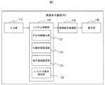
図1は、本発明の第一の実施形態の映像表示装置の構成図である。 FIG. 1 is a configuration diagram of a video display device according to a first embodiment of the present invention.
本実施形態の映像表示装置100は、例えばテレビやプロジェクタなどであり、図1に示されるように、入力部110、システム制御部120、映像信号処理部130、表示部140からなる。 The
入力部110は、ユーザの手の位置情報が含まれるデータを取得する装置であり、例えば、TOF(Time of flight)センサ機能を有する赤外線カメラ、ステレオカメラ、RGBカメラなどである。入力部110に用いるカメラは、特に、限定されず、ユーザに対して画像認識し、手の位置を検出するために最終的に、得た画像をセンシングデータに変換するための撮像画像を得る機能を有すればよい。また入力部110は、カメラではなく、ユーザが手で持って操作をおこなう空中マウスや空中コントローラなどの、ユーザの手の位置が検出できるセンシングデータを取得するポインティングデバイスなどでもよい。 The
システム制御部120は、ユーザの手の位置を検出し、適切な位置に操作領域を設定するためのデータ処理をおこなう部分である。システム制御部120は、CPUが、メモリ上に記憶されているソフトウェアモジュールを実行することにより実現してもよいし、専用のハードウェア回路により実現してもよい。 The
システム制御部120は、手の位置検出部121、位置判定処理部122、操作領域設定部123、フィードバック表示設定部125の機能を実現する部分を有する。 The
手の位置検出部121は、入力部110で取得したセンシングデータから手の位置を検出する部分である。位置判定処理部122は、手の位置と操作領域の位置関係を判定する部分である。操作領域設定部123は、操作領域を設定する部分である。フィードバック表示設定部125は、前記フィードバック表示を設定する部分である。 The hand
映像信号処理部130は、システム制御部120から指示とデータを受け取り、表示部140に表示するための映像信号を作成する部分である。 The video
表示部140は、映像信号に基づき、ユーザに映像信号を表示する部分であり、例えば、LCD(Liquid Crystal Display)、PDP(Plasma Display Panel)、プロジェクタ、などの静止画像や動画像を表示可能な表示装置である。 The
次に、図2を用いて本発明の第一の実施形態に係る映像表示装置100による前記フィードバック表示の設定処理について説明する。 Next, the feedback display setting process by the
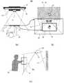
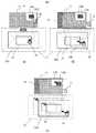
図2は、本発明の第一の実施形態に係る映像表示装置100をユーザが操作する際の概観について説明する図である。 FIG. 2 is a diagram illustrating an overview when the user operates the
本発明の第一の実施形態に係る映像表示装置100の表示部140は、例えばテレビのディスプレイ10や、プロジェクタの投射面17となる。 The
本発明の第一の実施形態に係る映像表示装置100の操作イメージは、図2(a)に示されるように、ユーザ30が操作対象の画面である表示部140で表示される操作画面18を見ながら仮想的な操作領域20内でジェスチャーにより操作し、当該操作を映像表示装置100が画像認識をし、その認識結果に基づいて操作に対応する表示を行う
本実施形態で、特に、キーポイントとなるのは、手の位置を検出することである。本実施形態の映像表示装置100の入力部110は、例えば赤外線カメラ12であり、赤外線を用いた測距機能を有することにより、画面から手までの距離を測定できるものとする。手32は、出っ張っており、ユーザ30の体の中で、赤外線カメラ12により認識しやすい部分であるといえる。As shown in FIG. 2A, the operation image of the
図2(b)に、本実施形態における赤外線カメラ12と、撮像領域面22と、操作領域20と、操作画面18の関係が示されている。 FIG. 2B shows a relationship among the
撮像領域面22は、ユーザの手の位置において、赤外線カメラ12が撮像可能な範囲を表す面である。操作画面18は、ユーザに提示するための動画像のコンテンツ、操作メニューや、前記フィードバック表示などを表示する領域である。本実施形態の映像表示装置100の操作画面18上に、静止画像19と、フィードバック表示設定部125で設定された、操作領域20におけるユーザの手の位置を表すポインタ26が表示される。ここで静止画像19の大きさは、操作画面18の大きさと同じとし、操作画面18に静止画像19の全体が見える。なお、操作画面18上に表示されるものは、静止画像の他に、動画、アニメーション、CG(Computer Graphics)映像などでもよい。また、ポインタ26は、図2(b)では、矢印のアイコンで示されているが、手の形をしたアイコン、丸、四角などの基本図形のアイコン、その他アニメのキャラクタのアイコンなどで示されてもよい。 The
映像表示装置100が、画像認識をして、ユーザの手32を検出すると、次に、手を認識した位置に応じて、操作画面18に対応する操作領域20を決定する。操作領域20は、ユーザ30に操作をおこなわせるための仮想的な領域であり、ユーザ30が立っている位置の赤外線カメラ12の撮像領域面22の中に作られるものとする。また、操作領域20は、操作画面18を、ユーザの手前の撮像領域面22上に、拡大・縮小したものであり、最初に、操作領域20を決定されたときには、ユーザ30の手32が、中心にくるようにする。そして、操作領域20は、手32の位置から操作画面18までの距離に応じて、手を伸ばした方向の延長線上が画面を指示するような領域として決定され、ちょうど、ハンズフリーのレーザポインタを使うようなイメージで、ユーザ30は、映像表示装置100に対して指示を与えることができる。 When the
なお、図2(b)に示されるように、操作領域20が決定された際に、ユーザ30に映像表示装置100に対する指示が可能であることを示すために、ポインタ26を表示するが、ポインタ26を表示せずに、操作画面18内の映像の明るさを変えることなどにより、操作が無効な状態から操作が可能となったことを提示するようにしてもよい。 As shown in FIG. 2B, when the
また、図2(c)に示されるように、本発明の映像表示装置では、操作を行わせるための操作領域は、2次元の面ではなく、操作領域20aのような3次元操作領域であってもよい。 In addition, as shown in FIG. 2C, in the video display device of the present invention, the operation area for performing the operation is not a two-dimensional surface but a three-dimensional operation area such as the
ここで、ユーザは操作領域20または操作領域20a内で、手の回転、手振り、押込みなどの所定のジェスチャー操作を行うことで映像表示装置100に対する指示を与え、操作画面18には、その指示の実行結果や前記フィードバック表示が表示される。 次に、図3ないし図6を用いて本発明の第一の実施形態に係る映像表示装置100による操作領域の設定処理と、前記フィードバック表示の設定方法について説明する。 Here, the user gives an instruction to the
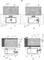
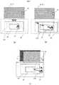
図3は、映像表示装置100が認識するユーザの手32の位置と前記フィードバック表示の対応関係を示しており、ユーザの手の位置が操作領域20から外れたときに、操作領域20に対する手の位置や方向、距離に応じて操作画面18に表示する前記フィードバック表示について説明する図である。 FIG. 3 shows the correspondence between the position of the user's
本実施形態の映像表示装置100では、ユーザが映像表示装置100に対して手32を出し、最初に操作領域20が設定されたときに、図3(a)に示されるようにポインタ26が操作画面18の中央に表示される。図3(b)に示されるように、ユーザが操作領域20の右の方向に手32を動かすと、ポインタ26はそれに応じて操作画面18の右方向に移動して、表示される。 In the
ここで、図3(c)に示されるように、図3(b)の状態から、ユーザが手32を右下方向に動かし、操作領域20の外側に移動させると、映像表示装置100は、静止画像19およびポインタ26を、操作画面18に対して右下方向へずらして表示させる。このとき、ポインタ26は操作画面18の外側にあるため、操作画面18には表示されない。また、静止画像19の左上の枠が見えるようになる。 Here, as shown in FIG. 3C, when the user moves the
同様に、図3(d)に示されるように、図3(b)の状態から、ユーザが手32を右上方向に動かし、操作領域20の外側に移動させると、映像表示装置100は、静止画像19およびポインタ26を、操作画面18に対して右上方向へずれて表示する。このとき、ポインタ26は操作画面18の外側にあるため、操作が面18には表示されない。また、静止画像19の左下の枠が見えるようになる。 Similarly, as shown in FIG. 3D, when the user moves the
図3(c)および(d)では、ユーザの手32が操作領域20から外れたときに、静止画像19の位置は手に追従して動く。すなわち、操作領域20と同じ大きさを持つ仮想面200の位置と操作画面18の位置とが対応している。つまり、ユーザの手32が操作領域20から出たときに、操作画面18に対する静止画像19のずれ方向およびずれる距離は、操作領域20に対する仮想面200のずれ方向および距離に対応する。 3C and 3D, when the user's
ここで、ユーザの手32が操作領域20から外れた際に、ユーザが見た静止画像19のずれる方向が、ユーザの手32の動く方向の逆であってもよい。すなわち、図4に示されるように、ユーザの手32が操作領域20から外れたときに、静止画像19の位置は操作領域20の位置と対応し、操作画面18の位置は仮想面200の位置と対応させてもよい。 Here, when the user's
図4(a)に示されるように、図3(b)の状態から、ユーザが手32を右下方向に動かし、操作領域20の外側に移動させると、映像表示装置100は、静止画像19を、操作画面18に対して左上方向へずらして表示させる。このとき、ポインタ26は操作画面18の内側に表示され、静止画像19の右下の枠が見えるようになる。 As shown in FIG. 4A, when the user moves the
また同様に、図4(b)に表示されるように、図3(b)の状態から、ユーザが手32を右上方向に動かし、操作領域20の外側に移動させると、映像表示装置100は、静止画像19を、操作画面18に対して左下方向へずらして表示させる。このとき、ポインタ26は操作画面18の内側に表示され、静止画像19の表示がずれて、右上の枠が見えるようになる。 Similarly, as shown in FIG. 4B, when the user moves the
なお、図3(c)、図3(d)、図4(a)と図4(b)に図示しないが、操作領域20および仮想面200は撮像領域面22の中にある。 Although not shown in FIGS. 3C, 3D, 4A, and 4B, the
なお、上記ではユーザの手32が操作領域20の外側に外れた際に、ポインタ26を操作画面18内に表示しないことによって、ユーザに操作が無効であることを提示しているが、手32が操作領域20の外側に外れた場合に、例えば操作画面18の全体明るさを低くすることなどで、ユーザに操作が無効であることを提示してもよい。 In the above description, when the user's
このように、本実施形態の映像表示装置100は、ユーザの手32が操作領域20の内側から外側に出て、且つユーザの手32が撮像領域22の内側にある場合に、ユーザの手32が操作領域20に対して外れている位置や方向、距離に応じて、操作画面18のフィードバック表示によりユーザに伝える。 As described above, the
次に、図5を用いて、ユーザの手32が操作領域20から外れたときのフィードバック表示の別の例について説明する。 Next, another example of feedback display when the user's
図5(a)および図5(b)には、ユーザの手32が操作領域20から外れたときの、操作画面18における別のフィードバック表示の一例が示される。 FIGS. 5A and 5B show an example of another feedback display on the
図5(a)に示されるように、図3(b)に示された状態から、ユーザが手32を右下方向に動かし、操作領域20の外側に移動させると、ポインタ26が操作画面18の右下の端に消え、操作領域20に対するユーザの手32が外れた方向や距離に応じて、画面の右下の端に点滅するフィードバックアイコン27が表示される。 As shown in FIG. 5A, when the user moves the
同様に、図5(b)に示されるように、図3(b)に示された状態から、ユーザが手32を右上方向に動かし、操作領域20の外側に移動させると、操作領域20に対するユーザの手32の外れた方向や距離に応じて、操作画面18の右上の端に点滅するフィードバックアイコン27が表示される。ここで、ユーザの手32が操作領域20からどの程度の距離で離れているかをユーザが理解できるように、フィードバックアイコン27の点滅間隔およびアイコンの大きさを操作領域20から手32の離れた距離に応じて変更する。フィードバックアイコン27の点滅間隔およびアイコンの大きさと、ユーザの手32と操作領域20の距離の対応関係の一例を図5(c)に示す。 Similarly, as shown in FIG. 5B, when the user moves the
図5(d)および図5(e)にはユーザの手32が操作領域20から外れたときの、操作画面18における別のフィードバック表示の一例が示される。 FIGS. 5D and 5E show another example of feedback display on the
図5(d)に示されるように、図3(b)に示された状態から、ユーザが手32を右下方向に動かし、操作領域20の外側に移動させると、ポインタ26が操作画面18の右下の端に消え、操作領域20に対するユーザの手32の外れた方向や距離に応じて、操作画面18に表示されている静止画像19の右下辺りにあたかも画面の一部が右下方向に引っ張られ、歪んでいるような表示効果28が表示される。 As shown in FIG. 5D, when the user moves the
同様に、図5(e)に示されるように、図3(b)に示された状態から、ユーザが手32を右上方向に動かし、操作領域20の外側に移動させると、操作画面18に表示されている静止画像19の右上辺りにあたかも画面の一部が右上方向に引っ張られ歪んでいるような表示効果28が表示される。なお、表示効果28の歪みの大きさおよび歪みの方向は、操作領域20に対して手32が外れた方向や距離に対応する。 Similarly, as shown in FIG. 5 (e), when the user moves the
次に、図6を用いて、映像表示装置100のフィードバック表示の設定処理の手順について説明する。 Next, the procedure of the feedback display setting process of the
図6は、本発明の第一の実施形態に係る映像表示装置100によるフィードバック表示の設定処理の手順を示すフローチャートである。 FIG. 6 is a flowchart showing a procedure of feedback display setting processing by the
操作画面18上でのフィードバック表示設定処理は、図1に示したシステム制御部120が行う処理である。 The feedback display setting process on the
まず、システム制御部120は、入力部110からのデータを解析して、ユーザ30の手32の認識処理を行う。 First, the
そして、手32を認識したときには(S600)、手32の位置に合わせて操作領域20を設定する(S601)。このとき、操作画面18上にポインタ26が表示される。 When the
次に、手32の位置の変化を認識し、手32の位置に応じて、操作画面18上のポインタ26の位置を動かす(S602)。 Next, the change in the position of the
さらに、再び、手32が認識できているかを判定し(S603)、手32が認識できないときには、操作領域20を削除する(S606)。このとき、操作画面18上のポインタ26も消去され、処理はS600に戻る。 Further, it is determined again whether the
手32が認識できており、手32の位置が操作領域20の内側から、操作領域20の外側に出た場合には(S604:Yes)、手32と操作領域20との相対位置を計算し(S607)、手32と操作領域20との相対位置を用いて、フィードバック表示設定部は操作画面18に対して、図3(c)、図3(d)、図4(a)、図4(b)、図5(a)、図5(b)、図5(d)および図5(e)に示したようにポインタ26が操作領域20から外れていることを表現する前記フィードバック表示を設定する(S608)。さらに、操作領域20に対する手32の距離が所定の閾値よりも大きいかを判定する(S609)。操作領域20に対する手32の距離がある閾値よりも大きい場合は(S609:Yes)、手32が操作領域から外れている前記フィードバック表示を終了し(S610)、操作領域20を削除する(S606)。このとき、操作画面18上のポインタ26も消去され、処理はS600に戻る。このとき、例えば操作画面18は、図3(c)、図3(d)、図4(a)、図4(b)、図5(a)、図5(b)、図5(d)および図5(e)に示される前記フィードバック表示を提示する状態から、元の状態(ポインタ26が無い図3(a))にすぐ戻してもよいが、操作領域22から手の外れた位置や方向をユーザにより分かりやすく伝えるために、アニメーションなどで少しずつ表示を変化させて操作画面18の元の状態までに、戻してもよい。 When the
一方、操作領域20に対する手32の距離が所定の閾値よりも小さい場合は(S609:No)、処理はS602に戻る。なお、手32が認識できており、手32の位置が操作領域20の内側にあり(S604:No)、ユーザ32が所定の操作で操作終了を指示したときには(S605)、処理を終了し、そうでないときには処理はS602に戻る。 On the other hand, when the distance of the
なお、上述の所定の閾値は、撮像領域の範囲であることが望ましい。すなわち、撮像領域外に手が移動した場合には、処理ができずに終了する。 Note that the above-described predetermined threshold is preferably the range of the imaging region. In other words, if the hand moves outside the imaging area, the process is terminated without being processed.
以上より、本発明の第三の実施形態では、映像表示装置100は、手32が操作領域20の内側から、操作領域20の外側に移動した際に、操作領域20に対する手32の位置や方向、距離を前記フィードバック表示によりユーザに提示する機能を提供するものである。 As described above, in the third embodiment of the present invention, when the
以上より、ユーザの手が操作領域から外れたことを意味する前記フィードバック表示を行うことにより、ユーザは操作が有効な操作領域に対する自分の手の位置を把握することができ、操作を円滑に行うことができる。 As described above, by performing the feedback display, which means that the user's hand is out of the operation area, the user can grasp the position of his / her hand with respect to the operation area where the operation is effective, and the operation is smoothly performed. be able to.
次に図7を用いて、操作領域が3次元空間である場合について説明する。 Next, a case where the operation area is a three-dimensional space will be described with reference to FIG.
図7(a)に示されるように、ユーザの手32の位置が操作領域20aの内側にある場合には、映像表示装置100の操作画面18上にポインタ26が表示さる。この状態から、図7(b)に示されるように、ユーザが手を奥行方向に動かして、操作領域20aから出たときに、操作画面18上では、あたかも静止画像19が奥行方向に遠のいたように表示される。また、図7(c)に示されるように、ユーザが手32をユーザの手前方向に動かして、操作領域20aから出たときに、操作画面18上では、あたかも静止画像19が手前に近づいたように表示される。このとき、操作が無効(ユーザによる手32の操作は反映されない)であることを表現するために、例えば操作画面18は暗く表示される。 As shown in FIG. 7A, when the position of the user's
このように、本発明の映像表示装置の映像表示装置100は、ユーザの手が、操作が有効である所定の空間領域から外れた際に、画面上にその状態を示すフィードバック表示を行うため、ユーザは円滑に操作を行うことができる。 As described above, the
以下、本発明に係る第二の実施形態を、図8ないし図10を用いて説明する。 Hereinafter, a second embodiment according to the present invention will be described with reference to FIGS.
第一の実施形態の映像表示装置100の表示制御方法は、手が操作領域内にある状態から、操作領域から外れた状態に変化したときに、ユーザに手が操作領域に対してどの方向にどの程度の距離で離れたかを提示する機能を提供するものであった。本実施形態では第一の実施形態の表示制御方法に加えて、手が操作領域に対して離れている状態を利用してジェスチャー操作を検出する機能を提供するものである。 In the display control method of the
図8は、本発明の第二の実施形態の映像表示装置の構成図である。 FIG. 8 is a configuration diagram of a video display apparatus according to the second embodiment of the present invention.
本実施形態の映像表示装置100でも、図8に示されるように、入力部110、システム制御部120、手の位置検出部121、位置判定処理部122、操作領域設定部123、フィードバック表示設定部125、映像信号処理部130、表示部140からなることは、第一の実施形態と同様であるが、システム制御部120にジェスチャー検出部126を有することが異なっている。 Also in the
ジェスチャー検出部126は、カメラ12の撮像範囲内において、ユーザの手32の所定の動きパターンである、いわゆるジェスチャーが行われたか否かを検出する部分である。 The
図9は、本発明の第二の実施形態に係る映像表示装置100による操作領域の外側におけるジェスチャー操作の検出方法について説明する図である。 FIG. 9 is a diagram for explaining a method of detecting a gesture operation outside the operation area by the
図5(a)および図5(b)に示されたようにユーザの手32が、操作領域20内にある状態から、操作領域20の外側に出たときに、ユーザの手32が操作領域20に対して離れた位置や方向、距離に応じて、画面の右下の端に点滅するフィードバックアイコン27が表示される。このとき、ジェスチャー検出部126は、ユーザの手32が操作領域20の外側、且つ撮像領域22内側にあるときに、ユーザの手32の動きが、映像表示装置100への指示に当たる所定の動きパターンであるか否かを判定する。ここで、前記所定の動きパターンは例えば図9(a)に示される上下に手振りをする動きや、図9(b)に示される操作領域20の外側を手32が一周回る動きや、ユーザが手を押込む動きや、ユーザが手を回転する動きなどの動きのパターンである。前記所定の動きパターンが検出されたら、映像表示100はそれを指示として解釈し、所定の操作を実行する。本発明の第二の実施形態の映像表示装置100は、ユーザの手32が操作領域20から外れており、且つ前記所定の手の動きパターンが検出された際に、画面18上にポップアップメッセージ29を表示する。映像表示装置100が実行する操作として、ポップアップメッセージ29を表示する他に、例えばプレゼンテーションのページめくり操作、ディスプレイの電源を切る操作などでもよい。 As shown in FIG. 5A and FIG. 5B, when the user's
以上より、手32は操作領域20から外れたことを認識したうえで、あえてその状態である所定の動きパターンを認識することにより、映像表示装置100に対してより多様な操作が可能となる。 As described above, by recognizing that the
図10は、本発明の第二の実施形態に係る映像表示装置100によるフィードバック表示の設定処理と、操作領域の外側でのジェスチャー操作の検出処理の手順を示すフローチャートである。 FIG. 10 is a flowchart showing a procedure of feedback display setting processing and gesture operation detection processing outside the operation region by the
まず、システム制御部120は、入力部110からのデータを解析して、ユーザ30の手32の認識処理を行う。 First, the
そして、手32を認識したときには(S800)、手32の位置に合わせて操作領域20を設定する(S801)。このとき、操作画面18上にポインタ26が表示される。 When the
次に、手32の位置の変化を認識し、手32の位置に応じて、操作画面18上のポインタ26の位置を動かす(S802)。 Next, the change in the position of the
さらに、再び、手32が認識できているかを判定し(S803)、手32が認識できないときには、操作領域20を削除する(S808)。このとき、操作画面18上のポインタ26も消去され、処理はS800に戻る。 Further, it is determined again whether the
手32が認識できており、手32の位置が操作領域20の内側から、操作領域20の外側に出た場合には(S804:Yes)、手32と操作領域20との相対位置を計算し(S808)、手32と操作領域20との相対位置を用いて、フィードバック表示設定部は操作画面18に対して、ポインタ26が操作領域20から外れていることを表現する前記フィードバック表示を設定する(S808)。さらに、操作領域20に対する手32の距離が所定の閾値よりも大きいかを判定する(S809)。操作領域20に対する手32の距離が所定の閾値よりも大きい場合は(S809:Yes)、手32が操作領域から外れている前記フィードバック表示を終了し(S812)、操作領域20を削除する(S806)。このとき、操作画面18上のポインタ26も消去され、処理はS800に戻る。一方、操作領域20に対する手32の距離が所定の閾値よりも小さい場合は(S809:No)、手振りや手の回転のどの所定の動きパターンがユーザによって行われたかを判定し(S810)、そのときは、例えば図9に示されたように画面上のポップアップメッセージを提示するなどの該所定の動きパターンに対応させた所定の動作を実行する(S811)。そしてS802に戻る。なお、手32が認識できており、手32の位置が操作領域20の内側にあり(S804:No)、ユーザ32が所定の操作で操作終了を指示したときには(S805)、処理を終了し、そうでないときには処理はS803に戻る。 When the
このように、本発明の第二の実施形態の表示制御方法によれば、手が操作領域から外れたときに、ユーザにその状況を提示して、さらにその状況を利用して、所定の手の動きパターンを操作として検出し、映像表示装置のより多様な入力操作が可能となる。 As described above, according to the display control method of the second embodiment of the present invention, when a hand is removed from the operation area, the situation is presented to the user, and the situation is further utilized to obtain a predetermined hand. Motion patterns can be detected as operations, and more various input operations of the video display device can be performed.
以下、本発明に係る第三の実施形態を、図11ないし図13を用いて説明する。 A third embodiment according to the present invention will be described below with reference to FIGS.
第一の実施形態の映像表示装置100の表示制御方法は、手が操作領域内にある状態から、操作領域から外れた状態に変化したときに、ユーザに手が操作領域に対してどの方向にどの程度の距離で離れたかを提示する機能を提供するものであった。本実施形態では、第一の実施形態の表示制御方式に加え、2つ目の操作領域を設けて、手が操作領域内にある状態から、第一の操作領域から外れた状態に変化したときに、ユーザに手が操作領域に対してどの方向にどの程度の距離で離れたかを提示し、第二の操作領域から手が外れたときに、手の移動に応じて操作領域を追従させるインタフェースを提供するものである。 In the display control method of the
まず、本発明の第三の映像表示装置100の構成について説明する。 First, the configuration of the third
本発明の第三の映像表示装置100の構成は、図1に示される第一の実施形態の映像表示装置と同様であり、入力部110、システム制御部120、手の位置検出部121、位置判定処理部122、操作領域設定部123、フィードバック表示設定部125、映像信号処理部130、表示部140からなる。本実施形態の映像表示装置100は、ユーザの手32を検出したときに、操作領域設定部123を用いて2つの操作領域を設定する。 The configuration of the third
次に、図11を用いて、本発明の第三の実施形態の映像表示装置100の操作領域について説明する。 Next, the operation area of the
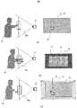
図11の第一の操作領域20は、第一実施形態ないし第二の実施形態の操作領域と同様に、赤外線カメラ12の撮像領域面22の中において、ユーザの手32を認識した位置に応じて決定される、ユーザ30の操作が有効となる仮想的な領域であり、操作画面18に対応する領域である。ここで、ユーザの手32が第一の操作領域20内に検出されれば、操作画面18上にポインタ26が表示される。 The
第二の操作領域1501は、第一の操作領域20と同様に、赤外線カメラ12の撮像領域22の中に作られる仮想的な領域であり、第二の操作領域1501の大きさは、第一の操作領域20より大きく、第二の操作領域1501の位置は、例えば第一の操作領域20と同じ中心位置で設定される。 Similar to the
本発明の第三の実施形態の映像表示装置100は、ユーザの手32が最初に認識されたときに、図11(a)に示されるようにユーザの手32の周囲に第一の操作領域20および第二の操作領域1501を設定する。このとき、第一の操作領域20の中心は、ユーザの手32であり、操作画面18の中心にポインタ26が表示される。図11(b)に示されるように、ユーザの手32が第一の操作領域20の外側へ出て、尚且つ、第二の操作領域1501の内側にある場合、映像表示装置100は、ポインタを右下方向に消し、第一の操作領域20に対する手32の位置や方向、距離に応じて、操作画面18に表示されている静止画像19を右下方向にずらして表示させる。このとき、ユーザの手32が第一操作領域20から出たときの操作画面18に対する静止画像19のずれ方向は、第一の操作領域20に対する仮想面200のずれ方向と対応する。また、静止画像19のずれ幅は、第一の操作領域20に対して手32が外れた距離に対応する。 When the user's
ここで、図11(c)に示されるように、ユーザが手32をさらに右下方向に動かして、第二操作領域1501の右下辺を越えたと認識されたとき、映像表示装置100は、第二の操作領域1501に対する手32の位置や方向、距離に追従して、第一操作領域20および第二の操作領域1501を右下方向に移動させる。 Here, as shown in FIG. 11C, when the user further moves the
ここで、操作画面18に、操作領域が移動可能な領域範囲を表す図形1502と、その移動可能な領域範囲に対する現在の操作領域の位置を表す図形1503が表示される。本実施形態では、図形1502は例えば撮像領域面22と対応し、図形1503は第二の操作領域1501と対応する。図11(c)に示されるように、ユーザの手32が第二の操作領域1501の外側に出たとき、第一の操作領域20と第二の操作領域1501がその手の動きにより移動されるが、それに従って図形1502における図形1503の表示位置が変化する。 Here, a graphic 1502 representing an area range in which the operation area can be moved and a graphic 1503 representing the position of the current operation area with respect to the movable area range are displayed on the
なお、第一の操作領域20は、第二の操作領域1501と常に同時に移動するため、図形1502と図形1503の表示は、第一の操作領域20が移動可能な範囲をも表すこととなる。つまり、図形1502と図形1503による前記フィードバック表示を提示することにより、ユーザは自分の手32の周囲にある操作領域が移動可能な範囲を理解することができる。 Since the
このように、第二の操作領域1501を設けることにより、ユーザは、自分の手32が操作領域から外れたことを、前記フィードバック表示で確認ができ、さらにその操作領域を任意の位置に移動させることができる。 By providing the
次に、図12を用いて本発明の第三の実施形態に係る映像表示装置100による操作領域の設定およびフィードバック表示の設定処理の手順について説明する。 Next, a procedure for setting an operation region and a feedback display by the
図12は、本発明の第三の実施形態に係る映像表示装置100による操作領域の設定およびフィードバック表示の設定処理の手順を示すフローチャートである。 FIG. 12 is a flowchart showing a procedure for setting an operation area and a feedback display by the
第一の操作領域20および第二操作領域1501の設定処理は、図1に示されたシステム制御部120が行う処理である。 The setting process of the
まず、システム制御部120は、入力部110からのデータを解析して、ユーザ30の手32の認識処理を行う。 First, the
そして、手32を認識したときには(S700)、手32の位置に合わせて操作領域20を設定する(S701)。このとき、操作画面18上にポインタ26が表示される。 When the
次に、手32の位置の変化を認識し、手32の位置に応じて、操作画面18上のポインタ26の位置を動かす(S702)。 Next, the change in the position of the
さらに、再び、手32が認識できているかを判定し(S703)、手32が認識できないときには、操作領域20を削除する(S706)。このとき、操作画面18上のポインタ26も消去され、処理はS700に戻る。 Furthermore, it is determined again whether the
手32が認識できており、手32の位置が第一の操作領域20の内側から、第一の操作領域20の外側に出た場合には(S704:Yes)、手32と第一の操作領域20との相対位置を計算し(S707)、手32と第一の操作領域20との相対位置を用いて、図10(b)に示されたような前記フィードバック表示を設定し(S708)、操作画面18に表示する。さらに、手32が認識できており、手32の位置が第二の操作領域1501の外側に外れたかを判定し(S709)、そのときには、手32の移動に応じて、第二の操作領域1501および第一の操作領域20を移動させる。すなわち、第二の操作領域1501および第一の操作領域20を手32の動きに追従して移動させる(S710)。次に、図11(c)に示されたように第一の操作領域の移動可能な範囲の位置を表現する前記フィードバック表示を更新し(S711)、そして、S702に戻る。手32が認識できており、手32の位置が操作領域20の外側に移動しない場合(S704:No)に、ユーザ32が所定の操作で操作終了を指示したときには(S705)、処理を終了する。 When the
なお、ユーザの手32が第一の操作領域20から外れて、まだ第二の操作領域1501の内側となったときには、2つの操作領域を手の動きと追従して移動させ、そして、ユーザの手32が第二の操作領域1501から外れたときには、第二の操作領域1501に対して手32が外れた方向や距離に応じて、操作画面18上に、手が操作領域から外れていることを示す前記フィードバック表示を設定するようにしてもよい。 When the user's
つまり、本発明の第三の実施形態の映像表示装置100は、ある手の位置を検出するタイミングにおいて、図13(a)に示されるように、手が第一の操作領域20の中にあり、次の手の位置を検出するタイミングにおいて、図13(b)に示されるように、手32が第一の操作領域20の外側に出て、かつ、まだ第二の操作領域1501の内側にあるときには、第一の操作領域20に対する手32の位置や方向、距離に追従して、第一の操作領域20および第二の操作領域1501を移動させる。そして、図13(c)に示されるように、図13(a)に示される状態から、次の手の位置を検出するタイミングで、手32が第二の操作領域1501の外側に出た(つまり、ユーザの手32は図13(b)に示される状態になったときよりも速く移動された)ときは、第二の操作領域1501に対して、手32が外れた方向や距離に応じて、操作画面18上に、手32が操作領域から外れていることを示すフィードバック画面を提示する。この仕組みにより、ユーザは手を動かし、操作領域から小さく外した場合には操作領域を手の動きに追従して移動させることができ、操作領域から大きく外した場合に、操作画面上の前記フィードバック表示により、手が操作領域から外れていることを認識することができる。 That is, the
このように、本発明の映像表示装置の表示制御方法によれば、操作中にユーザの手が設定された仮想の操作領域から外れた際に、画面上でその状況を前記フィードバック表示で分かりやすく伝えられ、さらに一度設定した操作領域が、ユーザが手の動きに応じて動的に変更されるため、キャリブレーションのタイミングを途中で決める必用がなく、操作性を向上させることができる。 As described above, according to the display control method of the video display device of the present invention, when the user's hand is out of the set virtual operation area during the operation, the situation can be easily understood on the screen by the feedback display. In addition, since the operation area once set is dynamically changed according to the movement of the hand by the user, it is not necessary to determine the timing of calibration halfway, and the operability can be improved.
以上、第一の実施形態ないし第三の実施形態で説明してきたように、操作中にユーザの手が設定された仮想の操作領域から外れた際に、画面上でその状況をフィードバック表示で分かりやすく伝えられるため、ユーザが操作を円滑に行える。 As described above in the first embodiment to the third embodiment, when the user's hand is out of the set virtual operation area during the operation, the situation can be understood on the screen by the feedback display. Since it is easily communicated, the user can perform the operation smoothly.
100…映像表示装置、110…入力部、130…映像信号処理部、140…表示部、121…手の位置検出部、122…位置判定処理部、123…操作領域設定部、124…手振り動作検出部、10…ディスプレイ、12…赤外線カメラ、14…LED、16…レンズ、18…操作画面、19…静止画像、20…操作領域、22…撮像領域面、26…ポインタ、30…ユーザ、32…手DESCRIPTION OF
Claims (6)
Translated fromJapanese前記ユーザに提示する映像を表示する表示部と、前記画像認識の結果に基づいて撮像領域面上で前記ユーザの手の位置の周囲に当該ユーザが操作可能な操作領域を設定すると共に、撮像領域内の当該ユーザの手の位置を検出した結果に基づいて当該ユーザの手の位置が当該操作領域の範囲外にある場合にその操作状況を前記表示部に表示させる制御部と、を備え、
前記制御部は、前記操作領域とは別の第二の操作領域を設定し、前記ユーザの手の位置が当該第二の操作領域の範囲外に移動した場合に、当該操作領域及び当該第二の操作領域を当該ユーザの手の位置が移動した方向にその距離だけ移動して各操作領域を再設定すると共に、当該再設定された当該第二の操作領域の撮像領域面内の位置を前記表示部に表示させることを特徴とする映像表示装置。By capturing images of the user, it performs image recognition on the image data of the image, based on the result ofthe image recognition, an image display device for presenting the status of the operation ofthe user,
A display unit for displaying an image to be presented totheuser,the user aroundthe position of the handbefore the SL user basedhave beenonan imaging area surface to results of theprevious SL image recognitionsets an operable operating areawith the control position of the hand ofthe user and displays the operation status when outside the range ofthe operation region on the display unitbased on a result of detectingthe position of the hand ofthe user ofan imaging area portion and,with a,
The control unit sets a second operation region different from the operation region, and when the position of the user's hand moves outside the range of the second operation region, the control region and the second operation region The operation area is moved by the distance in the direction in which the position of the user's hand has moved to reset each operation area, and the position of the reset second operation area in the imaging area plane is image display device comprising Rukotois displayed on the display unit.
前記制御部は、前記ユーザの手の位置が前記操作領域の範囲外にある場合に、当該操作領域から当該ユーザの手の位置までの距離と方向が分かるように前記表示部に表示させることを特徴とする映像表示装置。The video display device according to claim 1,
Wherein, when the position of the hand of the user is outside the range of the operation region, that is displayed on the display unit so that the distance and direction can be known fromthe operation area to the position of the hand ofthe userIt characterizedmovies image display device.
前記制御部は、前記ユーザの手の位置が前記操作領域の範囲外にある場合であって、当該ユーザの手が所定の動きをした場合には、当該所定の動きを所定の操作として検出し、当該所定の操作に対する表示を前記表示部に行わせることを特徴とする映像表示装置。The video display device according to claim 1,
Wherein, in a case where the position of the hand of the user is outside the range of the operation region, when the hand ofthe user has a predetermined motion detects the predetermined movement as a predetermined operation ,film image display deviceyou characterized in that to perform the display with respect tothe predetermined operation onthe display unit.
映像表示装置に備えられる表示部により、前記ユーザに提示する映像を表示する表示ステップと、映像表示装置に備えられる制御部により、前記画像認識の結果に基づいて撮像領域面上で前記ユーザの手の位置の周囲に当該ユーザが操作可能な操作領域を設定すると共に、撮像領域内の当該ユーザの手の位置を検出した結果に基づいて当該ユーザの手の位置が当該操作領域の範囲外にある場合にその操作状況を前記表示ステップでの前記表示部に表示させる制御ステップと、を有し、
前記制御ステップでは、前記制御部により、前記操作領域とは別の第二の操作領域を設定し、前記ユーザの手の位置が当該第二の操作領域の範囲外に移動した場合に、当該操作領域及び当該第二の操作領域を当該ユーザの手の位置が移動した方向にその距離だけ移動して各操作領域を再設定すると共に、当該再設定された当該第二の操作領域の撮像領域面内の位置を前記表示ステップでの前記表示部に表示させることを特徴とする映像表示方法。A video display method for capturing an image of a user, performing image recognition on image data of the image, and presenting a status of the user's operation based on a result of the image recognition,
The display unit provided in the video display device displays a video to be presented to the user, and the control unit provided in the video display device uses the user's hand on the imaging area surface based on the result of the image recognition. An operation area operable by the user is set around the position of the user, and the position of the user's hand is outside the range of the operation area based on the result of detecting the position of the user's hand in the imaging area. A control step for displaying the operation status on the display unit in the display step in the case,
In the control step, the control unit sets a second operation area different from the operation area, and the operation is performed when the position of the user's hand moves outside the range of the second operation area. The area and the second operation area are moved by the distance in the direction in which the position of the user's hand has moved to reset each operation area, and the imaging area plane of the reset second operation areaFilm image displayhowto, characterized inthat to display the position of the inner on the display unit in the display step.
前記制御ステップでは、前記制御部により、前記ユーザの手の位置が前記操作領域の範囲外にある場合に、当該操作領域から当該ユーザの手の位置までの距離と方向が分かるように前記表示ステップでの前記表示部に表示させることを特徴とする映像表示方法。The video display method according to claim 4,
In the control step, when the position of the user's hand is outside the range of the operation area, the display step is performed so that the distance and direction from the operation area to the position of the user's hand can be known by the control unit. And displaying the image on the display unit .
前記制御ステップでは、前記制御部により、前記ユーザの手の位置が前記操作領域の範囲外にある場合であって、当該ユーザの手が所定の動きをした場合には、当該所定の動きを所定の操作として検出し、当該所定の操作に対する表示を前記表示ステップでの前記表示部に行わせることを特徴とする映像表示方法。The video display method according to claim 4,
In the control step, when the position of the user's hand is outside the range of the operation area by the control unit and the user's hand has made a predetermined movement, the predetermined movement is predetermined. of detected as an operation,film images displayedhow to characterized in thatto perform the display with respect to the predetermined operation on the display unit in the displaystep.
Priority Applications (1)
| Application Number | Priority Date | Filing Date | Title |
|---|---|---|---|
| JP2012164311AJP5921981B2 (en) | 2012-07-25 | 2012-07-25 | Video display device and video display method |
Applications Claiming Priority (1)
| Application Number | Priority Date | Filing Date | Title |
|---|---|---|---|
| JP2012164311AJP5921981B2 (en) | 2012-07-25 | 2012-07-25 | Video display device and video display method |
Publications (2)
| Publication Number | Publication Date |
|---|---|
| JP2014026355A JP2014026355A (en) | 2014-02-06 |
| JP5921981B2true JP5921981B2 (en) | 2016-05-24 |
Family
ID=50199965
Family Applications (1)
| Application Number | Title | Priority Date | Filing Date |
|---|---|---|---|
| JP2012164311AActiveJP5921981B2 (en) | 2012-07-25 | 2012-07-25 | Video display device and video display method |
Country Status (1)
| Country | Link |
|---|---|
| JP (1) | JP5921981B2 (en) |
Families Citing this family (10)
| Publication number | Priority date | Publication date | Assignee | Title |
|---|---|---|---|---|
| US20150268728A1 (en)* | 2014-03-18 | 2015-09-24 | Fuji Xerox Co., Ltd. | Systems and methods for notifying users of mismatches between intended and actual captured content during heads-up recording of video |
| JP6322029B2 (en)* | 2014-03-31 | 2018-05-09 | 株式会社メガチップス | Gesture detection device, operation method of gesture detection device, and control program |
| JP6528193B2 (en)* | 2015-02-10 | 2019-06-12 | 任天堂株式会社 | Electronics |
| JP6632298B2 (en)* | 2015-09-29 | 2020-01-22 | キヤノン株式会社 | Information processing apparatus, information processing method and program |
| JP6834197B2 (en)* | 2016-07-05 | 2021-02-24 | 株式会社リコー | Information processing equipment, display system, program |
| EP3267289B1 (en) | 2016-07-05 | 2019-02-27 | Ricoh Company, Ltd. | Information processing apparatus, position information generation method, and information processing system |
| JP6328304B1 (en)* | 2017-07-25 | 2018-05-23 | 株式会社ネットアプリ | Input/Output System |
| JP6730552B2 (en)* | 2018-05-14 | 2020-07-29 | 株式会社ユピテル | Electronic information system and its program |
| JP6658809B2 (en)* | 2018-07-04 | 2020-03-04 | 株式会社ニコン | Detection device, electronic device, detection method, and program |
| WO2021001894A1 (en)* | 2019-07-01 | 2021-01-07 | 三菱電機株式会社 | Display control device and display control method |
Family Cites Families (5)
| Publication number | Priority date | Publication date | Assignee | Title |
|---|---|---|---|---|
| JP5427385B2 (en)* | 2008-09-29 | 2014-02-26 | 日立コンシューマエレクトロニクス株式会社 | Operation control device and operation display method |
| JP4701424B2 (en)* | 2009-08-12 | 2011-06-15 | 島根県 | Image recognition apparatus, operation determination method, and program |
| JP5412227B2 (en)* | 2009-10-05 | 2014-02-12 | 日立コンシューマエレクトロニクス株式会社 | Video display device and display control method thereof |
| JP2011175405A (en)* | 2010-02-24 | 2011-09-08 | Panasonic Corp | Display device and operable range display method in display device |
| JP5935529B2 (en)* | 2012-06-13 | 2016-06-15 | ソニー株式会社 | Image processing apparatus, image processing method, and program |
- 2012
- 2012-07-25JPJP2012164311Apatent/JP5921981B2/enactiveActive
Also Published As
| Publication number | Publication date |
|---|---|
| JP2014026355A (en) | 2014-02-06 |
Similar Documents
| Publication | Publication Date | Title |
|---|---|---|
| JP5921981B2 (en) | Video display device and video display method | |
| JP7574208B2 (en) | Input detection in a virtual reality system based on pinch-and-pull gestures | |
| JP5412227B2 (en) | Video display device and display control method thereof | |
| US9454837B2 (en) | Image processing apparatus, method, and computer-readable storage medium calculating size and position of one of an entire person and a part of a person in an image | |
| JP5167523B2 (en) | Operation input device, operation determination method, and program | |
| JP5802667B2 (en) | Gesture input device and gesture input method | |
| JP5921835B2 (en) | Input device | |
| CN105190477B (en) | Head-mounted display device for user interaction in an augmented reality environment | |
| US20170293351A1 (en) | Head mounted display linked to a touch sensitive input device | |
| JP5515067B2 (en) | Operation input device, operation determination method, and program | |
| JP5839220B2 (en) | Information processing apparatus, information processing method, and program | |
| JP5808712B2 (en) | Video display device | |
| WO2012039140A1 (en) | Operation input apparatus, operation input method, and program | |
| US20130154913A1 (en) | Systems and methods for a gaze and gesture interface | |
| US20140022171A1 (en) | System and method for controlling an external system using a remote device with a depth sensor | |
| US9544556B2 (en) | Projection control apparatus and projection control method | |
| CN108536273A (en) | Man-machine menu mutual method and system based on gesture | |
| JP2012027515A (en) | Input method and input device | |
| JP2010205223A (en) | System and device for control following gesture for virtual object | |
| JP6270495B2 (en) | Information processing apparatus, information processing method, computer program, and storage medium | |
| JP2016126687A (en) | Head-mounted display, operation reception method, and operation reception program | |
| KR101394604B1 (en) | method for implementing user interface based on motion detection and apparatus thereof | |
| US20240053832A1 (en) | Information processing apparatus, information processing method, and non-transitory computer readable medium | |
| WO2014181587A1 (en) | Portable terminal device | |
| WO2016102948A1 (en) | Coherent touchless interaction with stereoscopic 3d images |
Legal Events
| Date | Code | Title | Description |
|---|---|---|---|
| RD02 | Notification of acceptance of power of attorney | Free format text:JAPANESE INTERMEDIATE CODE: A7422 Effective date:20140311 | |
| RD04 | Notification of resignation of power of attorney | Free format text:JAPANESE INTERMEDIATE CODE: A7424 Effective date:20140317 | |
| RD04 | Notification of resignation of power of attorney | Free format text:JAPANESE INTERMEDIATE CODE: A7424 Effective date:20140318 | |
| RD04 | Notification of resignation of power of attorney | Free format text:JAPANESE INTERMEDIATE CODE: A7424 Effective date:20140319 | |
| A711 | Notification of change in applicant | Free format text:JAPANESE INTERMEDIATE CODE: A712 Effective date:20140908 | |
| A621 | Written request for application examination | Free format text:JAPANESE INTERMEDIATE CODE: A621 Effective date:20150304 | |
| A131 | Notification of reasons for refusal | Free format text:JAPANESE INTERMEDIATE CODE: A131 Effective date:20160119 | |
| A977 | Report on retrieval | Free format text:JAPANESE INTERMEDIATE CODE: A971007 Effective date:20160120 | |
| A521 | Request for written amendment filed | Free format text:JAPANESE INTERMEDIATE CODE: A523 Effective date:20160222 | |
| TRDD | Decision of grant or rejection written | ||
| A01 | Written decision to grant a patent or to grant a registration (utility model) | Free format text:JAPANESE INTERMEDIATE CODE: A01 Effective date:20160315 | |
| A61 | First payment of annual fees (during grant procedure) | Free format text:JAPANESE INTERMEDIATE CODE: A61 Effective date:20160413 | |
| R150 | Certificate of patent or registration of utility model | Ref document number:5921981 Country of ref document:JP Free format text:JAPANESE INTERMEDIATE CODE: R150 | |
| S111 | Request for change of ownership or part of ownership | Free format text:JAPANESE INTERMEDIATE CODE: R313111 | |
| R350 | Written notification of registration of transfer | Free format text:JAPANESE INTERMEDIATE CODE: R350 | |
| R250 | Receipt of annual fees | Free format text:JAPANESE INTERMEDIATE CODE: R250 | |
| R250 | Receipt of annual fees | Free format text:JAPANESE INTERMEDIATE CODE: R250 | |
| R250 | Receipt of annual fees | Free format text:JAPANESE INTERMEDIATE CODE: R250 | |
| R250 | Receipt of annual fees | Free format text:JAPANESE INTERMEDIATE CODE: R250 |