JP5919554B2 - POLYMER ELECTROLYTE MEMBRANE, MEMBRANE ELECTRODE ASSEMBLY, POLYMER ELECTROLYTE FUEL CELL, AND METHOD FOR PRODUCING POLYMER ELECTROLYTE MEMBRANE - Google Patents
POLYMER ELECTROLYTE MEMBRANE, MEMBRANE ELECTRODE ASSEMBLY, POLYMER ELECTROLYTE FUEL CELL, AND METHOD FOR PRODUCING POLYMER ELECTROLYTE MEMBRANEDownload PDFInfo
- Publication number
- JP5919554B2 JP5919554B2JP2012123714AJP2012123714AJP5919554B2JP 5919554 B2JP5919554 B2JP 5919554B2JP 2012123714 AJP2012123714 AJP 2012123714AJP 2012123714 AJP2012123714 AJP 2012123714AJP 5919554 B2JP5919554 B2JP 5919554B2
- Authority
- JP
- Japan
- Prior art keywords
- porous
- sheet
- polymer electrolyte
- nanofibers
- core material
- Prior art date
- Legal status (The legal status is an assumption and is not a legal conclusion. Google has not performed a legal analysis and makes no representation as to the accuracy of the status listed.)
- Expired - Fee Related
Links
Images


Classifications
- Y—GENERAL TAGGING OF NEW TECHNOLOGICAL DEVELOPMENTS; GENERAL TAGGING OF CROSS-SECTIONAL TECHNOLOGIES SPANNING OVER SEVERAL SECTIONS OF THE IPC; TECHNICAL SUBJECTS COVERED BY FORMER USPC CROSS-REFERENCE ART COLLECTIONS [XRACs] AND DIGESTS
- Y02—TECHNOLOGIES OR APPLICATIONS FOR MITIGATION OR ADAPTATION AGAINST CLIMATE CHANGE
- Y02E—REDUCTION OF GREENHOUSE GAS [GHG] EMISSIONS, RELATED TO ENERGY GENERATION, TRANSMISSION OR DISTRIBUTION
- Y02E60/00—Enabling technologies; Technologies with a potential or indirect contribution to GHG emissions mitigation
- Y02E60/30—Hydrogen technology
- Y02E60/50—Fuel cells
- Y—GENERAL TAGGING OF NEW TECHNOLOGICAL DEVELOPMENTS; GENERAL TAGGING OF CROSS-SECTIONAL TECHNOLOGIES SPANNING OVER SEVERAL SECTIONS OF THE IPC; TECHNICAL SUBJECTS COVERED BY FORMER USPC CROSS-REFERENCE ART COLLECTIONS [XRACs] AND DIGESTS
- Y02—TECHNOLOGIES OR APPLICATIONS FOR MITIGATION OR ADAPTATION AGAINST CLIMATE CHANGE
- Y02P—CLIMATE CHANGE MITIGATION TECHNOLOGIES IN THE PRODUCTION OR PROCESSING OF GOODS
- Y02P70/00—Climate change mitigation technologies in the production process for final industrial or consumer products
- Y02P70/50—Manufacturing or production processes characterised by the final manufactured product
Landscapes
- Manufacture Of Macromolecular Shaped Articles (AREA)
- Nonwoven Fabrics (AREA)
- Conductive Materials (AREA)
- Fuel Cell (AREA)
Description
Translated fromJapanese本発明は、高分子電解質膜、膜電極接合体、高分子電解質型燃料電池および高分子電解質膜の製造方法に関し、特に、高分子電解質膜の多孔質芯材の改良に関する。 The present invention relates to a polymer electrolyte membrane, a membrane electrode assembly, a polymer electrolyte fuel cell, and a method for producing a polymer electrolyte membrane, and more particularly to improvement of a porous core material of the polymer electrolyte membrane.
ナノファイバは、数十から数百nmの繊維径を有する極細繊維であり、繊維が極細化されることにより、従来の繊維とは異なる物性を示す。そのため、ナノファイバ自体またはナノファイバ製品(例えば、不織布)は、エネルギー、バイオテクノロジー、ヘルスケアなどの様々な分野で注目されている。特に、ナノファイバ不織布は、ナノファイバの小さな繊維径に由来して、従来の不織布に比べて孔径を小さくできるため、広い分野での活用が期待される。 Nanofibers are ultrafine fibers having a fiber diameter of several tens to several hundreds of nanometers, and exhibit physical properties different from those of conventional fibers when the fibers are ultrafine. Therefore, nanofibers themselves or nanofiber products (for example, non-woven fabrics) have attracted attention in various fields such as energy, biotechnology, and healthcare. In particular, nanofiber nonwoven fabrics are expected to be used in a wide range of fields because they can be made smaller in pore diameter than conventional nonwoven fabrics due to the small fiber diameter of nanofibers.
ナノファイバ不織布は、例えば、エネルギー分野では、燃料電池における電解質膜の支持体(多孔質芯材)や、アルカリ電池やリチウム電池などの一次または二次電池におけるセパレータなどとして注目されている。 For example, in the energy field, nanofiber nonwoven fabrics are attracting attention as electrolyte membrane supports (porous core materials) in fuel cells, separators in primary or secondary batteries such as alkaline batteries and lithium batteries, and the like.
特許文献1には、電界紡糸法により形成されたナノファイバ不織布の空隙にイオン伝導性樹脂を充填した高分子電解質膜が開示されている。特許文献1では、ターゲットに、ナノファイバを構成するポリマーの溶液を噴射して紡糸することにより、ナノファイバ不織布を形成し、さらにイオン伝導性樹脂の溶液で処理することにより形成した複合膜を、高分子電解質膜として使用している。特許文献1では、ターゲットとなる基材に電界紡糸することにより、ナノファイバ不織布を形成し、これをイオン伝導性樹脂で処理したものを高分子電解質膜として用いている。このような方法では、ポリマー溶液の噴射に伴い、ナノファイバが基材上に堆積する。 Patent Document 1 discloses a polymer electrolyte membrane in which voids of a nanofiber nonwoven fabric formed by an electrospinning method are filled with an ion conductive resin. In Patent Document 1, a nanofiber nonwoven fabric is formed by jetting and spinning a polymer solution constituting a nanofiber on a target, and a composite membrane formed by processing with a solution of an ion conductive resin is further formed. Used as a polymer electrolyte membrane. In Patent Document 1, a nanofiber nonwoven fabric is formed by electrospinning on a target substrate, and this is treated with an ion conductive resin and used as a polymer electrolyte membrane. In such a method, nanofibers are deposited on the substrate as the polymer solution is jetted.
しかしながら、基材の表面に接するナノファイバは、ナノファイバが堆積していくうちに、基材の表面の形状が転写されて、少し押し潰された状態となる。押し潰されたナノファイバは、ナノファイバ不織布の面方向における最大繊維径が大きくなる。そのため、ナノファイバ不織布は、基材とは反対側の表面においては、ナノファイバ不織布の面方向における最大繊維径を小さく維持できるものの、基材に接する表面においては、接触面積が大きくなる。つまり、基材に接する表面と、基材とは反対側の表面とで、繊維の状態が異なることになり、結果として、特性にも違いが生じる。 However, the nanofibers in contact with the surface of the base material are in a state of being slightly crushed because the shape of the surface of the base material is transferred as the nanofibers are deposited. The crushed nanofiber has a large maximum fiber diameter in the surface direction of the nanofiber nonwoven fabric. Therefore, although the nanofiber nonwoven fabric can keep the maximum fiber diameter small in the surface direction of the nanofiber nonwoven fabric on the surface opposite to the substrate, the contact area becomes large on the surface in contact with the substrate. That is, the fiber state is different between the surface in contact with the base material and the surface opposite to the base material, resulting in a difference in characteristics.
一方、高分子電解質膜の電気抵抗が高いと、燃料電池の内部抵抗が高くなり、発電効率が低下する。上記のような方法で得られたナノファイバ不織布を、高分子電解質膜として用いると、アノードおよびカソードのいずれか一方には、ナノファイバが少し押し潰され、ナノファイバ不織布の面方向における最大繊維径が大きくなった状態の表面が接することになり、接触面積が大きくなるため、電気抵抗が大きくなりやすい。電気抵抗が高くなると、発電効率の低下を招く。 On the other hand, when the electric resistance of the polymer electrolyte membrane is high, the internal resistance of the fuel cell increases and the power generation efficiency decreases. When the nanofiber nonwoven fabric obtained by the above method is used as a polymer electrolyte membrane, the nanofiber is slightly crushed on either the anode or the cathode, and the maximum fiber diameter in the surface direction of the nanofiber nonwoven fabric Since the surface in the state of increasing is in contact and the contact area is increased, the electrical resistance is likely to increase. When the electrical resistance increases, the power generation efficiency decreases.
本発明の目的は、高分子電解質膜とアノードおよびカソードとの接触面における電気抵抗を低減可能な高分子電解質膜、膜電極接合体、高分子電解質膜型燃料電池および高分子電解質膜の製造方法を提供することである。 An object of the present invention is to provide a polymer electrolyte membrane, a membrane electrode assembly, a polymer electrolyte membrane fuel cell, and a method for producing a polymer electrolyte membrane that can reduce electrical resistance at the contact surface between the polymer electrolyte membrane and the anode and cathode Is to provide.
本発明の一局面は、第1表面およびその反対側の第2表面を有するシート形状の多孔質芯材と、
多孔質芯材に含浸させた高分子電解質と、を具備し、
多孔質芯材は、堆積されたナノファイバで形成されたナノファイバのマトリックス構造を有する一対の多孔質シートの接合物であり、一対の多孔質シートの、堆積によりナノファイバが押し潰された側の表面同士が接合されており、一対の多孔質シートのナノファイバが押し潰された側の裏面がそれぞれ第1表面および第2表面であり、
多孔質芯材の面方向におけるナノファイバの最大繊維径の平均を、第1表面近傍および第2表面近傍と、多孔質芯材の厚さ方向の中心部とで比較したとき、第1表面近傍におけるナノファイバの最大繊維径の平均Ds1および第2表面近傍におけるナノファイバの最大繊維径の平均Ds2が、多孔質芯材の厚さ方向の中心部におけるナノファイバの最大繊維径の平均Dcより小さくなっている、高分子電解質膜に関する。第1表面近傍は、第1表面から多孔質芯材の全体の厚さの10%の厚さを有する領域であり、第2表面近傍は、第2表面から多孔質芯材の全体の厚さの10%の厚さを有する領域である。One aspect of the present invention is a sheet-shaped porous core material having a first surface and a second surface opposite tothe first surface;
Comprising a polymer electrolyte impregnated in a porous core material,
The porous core material is a joined product of a pair of porous sheets having a matrix structure of nanofibers formed by deposited nanofibers, and the side of the pair of porous sheets on which the nanofibers are crushed by deposition And the back surfaces on the side where the nanofibers of the pair of porous sheets are crushed are the first surface and the second surface, respectively.
When the average of the maximum fiber diameters of the nanofibers in the plane direction of the porous core material is compared between the vicinity of the first surface and the second surface and the central portion in the thickness direction of the porous core material, the vicinity of the first surface The average Ds1 of the maximum fiber diameters of the nanofibers and the average Ds2 of the maximum fiber diameters of the nanofibers in the vicinity of the second surface are smaller than the average Dc of the maximum fiber diameters of the nanofibers at the center in the thickness direction of the porous core material. The present invention relates to a polymer electrolyte membrane. The vicinity of the first surface is a region having a thickness of 10% of the total thickness of the porous core material from the first surface, and the vicinity of the second surface is the total thickness of the porous core material from the second surface. Is a region having a thickness of 10%.
本発明の他の一局面は、上記の高分子電解質膜と、高分子電解質膜の一方の表面に形成されたアノードと、高分子電解質膜の他方の表面に形成されたカソードと、を具備する、膜電極接合体に関する。 Another aspect of the present invention includes the above-described polymer electrolyte membrane, an anode formed on one surface of the polymer electrolyte membrane, and a cathode formed on the other surface of the polymer electrolyte membrane. The present invention relates to a membrane electrode assembly.
本発明のさらに他の一局面は、上記の膜電極接合体と、アノードに接触するとともに、アノードに燃料を供給する燃料流路を有するアノード側セパレータと、カソードに接触するとともに、カソードに酸化剤を供給するカソード側セパレータと、を具備する高分子電解質型燃料電池に関する。 Still another aspect of the present invention is the above-described membrane electrode assembly, an anode separator having a fuel flow path for contacting the anode and supplying fuel to the anode, the cathode contacting the cathode, and the oxidizing agent for the cathode The present invention relates to a polymer electrolyte fuel cell comprising:
本発明の別の一局面は、(i)電界紡糸法により形成されたナノファイバのマトリックス構造を有し、かつ第1表面およびその反対側の第2表面を有するシート形状の多孔質芯材を準備する工程と、(ii)多孔質芯材に高分子電解質を含浸させる工程と、を有し、ナノファイバの多孔質芯材の面方向における最大繊維径の平均を、第1表面近傍および第2表面近傍と、多孔質芯材の厚さ方向の中心部とで比較したとき、第1表面近傍におけるナノファイバの最大繊維径の平均Ds1および第2表面近傍におけるナノファイバの最大繊維径の平均Ds2が、多孔質芯材の厚さ方向の中心部におけるナノファイバの最大繊維径の平均Dcより小さくなっている、高分子電解質膜の製造方法に関する。第1表面近傍は、第1表面から多孔質芯材の全体の厚さの10%の厚さを有する領域であり、第2表面近傍は、第2表面から多孔質芯材の全体の厚さの10%の厚さを有する領域である。工程(i)は、(a)基材シートをナノファイバ形成空間に供給する工程と、(b)ナノファイバ形成空間において、溶媒および溶媒に溶解した樹脂原料を含む原料液から静電気力によりナノファイバを生成させるとともに、生成したナノファイバを基材シートの主面に堆積させて、ナノファイバのマトリックス構造を有する多孔質シートを形成する工程と、(c)一対の多孔質シートを、基材シートの主面と接触していた表面同士を対向させて接合し、一対の多孔質シートの基材シートの主面と接触していなかった表面をそれぞれ第1表面およびその反対側の第2表面とする多孔質芯材を形成する工程と、を有する。Another aspect of the present invention is: (i) a sheet-shaped porous core material having a matrix structure of nanofibers formed by electrospinning and having a first surface and a second surface opposite to the first surface. And (ii) impregnating the porous core material with the polymer electrolyte, and calculating the average of the maximum fiber diameters in the surface direction of the porous core material of the nanofibers in the vicinity of the first surface and the first 2 When the vicinity of the surface is compared with the central portion in the thickness direction of the porous core, the average Ds1 of the maximum fiber diameter of the nanofibers near the first surface and the average of the maximum fiber diameter of the nanofibers near the second surface The present invention relates to a method for producing a polymer electrolyte membrane, wherein Ds2 is smaller than the average Dc of the maximum fiber diameters of nanofibers in the central portion in the thickness direction of the porous core material. The vicinity of the first surface is a region having a thickness of 10% of the total thickness of the porous core material from the first surface, and the vicinity of the second surface is the total thickness of the porous core material from the second surface. Is a region having a thickness of 10%.Step (i) includes: (a) supplying a base sheet to the nanofiber formation space; and (b) nanofiber by electrostatic force from a raw material liquid containing a solvent and a resin raw material dissolved in the solvent in the nanofiber formation space. And forming a porous sheet having a nanofiber matrix structure by depositing the generated nanofibers on the main surface of the base sheet, and (c) a pair of porous sheets, The surfaces that have been in contact with the main surfaces of the pair are opposed to each other, and the surfaces that are not in contact with the main surfaces of the base sheet of the pair of porous sheets are respectively the first surface and the opposite second surface. Forming a porous core material.
本発明のさらに別の一局面は、第1および第2ラインの上流から下流にそれぞれ長尺の第1および第2基材シートを搬送し、上流側で、第1および第2基材シートの主面にそれぞれ第1および第2多孔質シートを形成し、下流側で、第1および第2多孔質シートを対向させて接合して多孔質芯材を得るとともに、多孔質芯材に高分子電解質を含浸させる、高分子電解質膜の製造方法であって、(i)第1および第2基材シートを、第1および第2ラインの上流側のナノファイバ形成空間に搬送する工程と、(ii)ナノファイバ形成空間において、溶媒および溶媒に溶解した樹脂原料を含む原料液から静電気力によりナノファイバを生成させるとともに、生成したナノファイバを搬送される第1および第2基材シートの主面にそれぞれ堆積させて、ナノファイバのマトリックス構造を有する第1および第2多孔質シートを形成する工程と、(iii)第1および第2ラインの下流側で、搬送される第1および第2多孔質シートから第1および第2基材シートを除去する工程と、(iv)第1および第2ラインの更に下流側で、搬送される第1および第2多孔質シートの第1および第2基材シートの主面と接触していた表面同士を対向させて接合して多孔質芯材を形成する工程と、を有する、高分子電解質膜の製造方法に関する。多孔質芯材は、第1表面およびその反対側の第2表面を有し、第1表面近傍におけるナノファイバの最大繊維径の平均Ds1および第2表面近傍におけるナノファイバの最大繊維径の平均Ds2が、多孔質芯材の厚さ方向の中心部におけるナノファイバの最大繊維径の平均Dcより小さく、第1表面近傍は、第1表面から多孔質芯材の全体の厚さの10%の厚さを有する領域であり、第2表面近傍は、第2表面から多孔質芯材の全体の厚さの10%の厚さを有する領域である。According to still another aspect of the present invention, the long first and second base sheets are conveyed from upstream to downstream of the first and second lines, respectively, and upstream of the first and second base sheets. The first and second porous sheets are formed on the main surface, respectively, and the first and second porous sheets are opposed to each other on the downstream side to obtain a porous core material. A method for producing a polymer electrolyte membrane impregnated with an electrolyte, comprising: (i) conveying the first and second substrate sheets to a nanofiber formation space upstream of the first and second lines; ii) In the nanofiber formation space, nanofibers are generated by electrostatic force from a raw material liquid containing a solvent and a resin raw material dissolved in the solvent, and the main surfaces of the first and second substrate sheets that are transported by the generated nanofibers Each deposited on Forming first and second porous sheets having a nanofiber matrix structure; and (iii) first and second porous sheets conveyed from the first and second porous sheets downstream of the first and second lines. A step of removing the second base sheet; and (iv) main surfaces of the first and second base sheets of the first and second porous sheets conveyed further downstream of the first and second lines. A method of manufacturing a polymer electrolyte membrane, the method comprising: forming a porous core material by facing and joining the surfaces that are in contact with each other. The porous core material has a first surface and a second surface opposite to the first surface, and an average Ds1 of the maximum fiber diameters of the nanofibers in the vicinity of the first surface and an average Ds2 of the maximum fiber diameters of the nanofibers in the vicinity of the second surface. Is smaller than the average Dc of the maximum fiber diameters of the nanofibers at the central portion in the thickness direction of the porous core material, and the vicinity of the first surface is 10% of the total thickness of the porous core material from the first surface. of a region having the second near the surface,Ru regions der having a total thickness of 10% of the thickness of the second surface of a porous corematerial.
本発明によれば、高分子電解質膜の多孔質芯材が、電界紡糸法により形成されたナノファイバのマトリックス構造を有するにも拘わらず、多孔質芯材の面方向におけるナノファイバの最大繊維径の平均を、多孔質芯材の両方の表面近傍において、厚さ方向の中心部における最大繊維径の平均よりも小さくできる。そのため、高分子電解質型燃料電池において、高分子電解質膜とアノードおよびカソードとの接触面における電気抵抗を低減できる。 According to the present invention, although the porous core material of the polymer electrolyte membrane has a nanofiber matrix structure formed by electrospinning, the maximum fiber diameter of the nanofibers in the plane direction of the porous core material Can be made smaller than the average of the maximum fiber diameters at the center in the thickness direction in the vicinity of both surfaces of the porous core material. Therefore, in the polymer electrolyte fuel cell, the electrical resistance at the contact surface between the polymer electrolyte membrane and the anode and cathode can be reduced.
[高分子電解質膜]
高分子電解質膜は、電界紡糸法により形成されたナノファイバのマトリックス構造を有し、かつ第1表面およびその反対側の第2表面を有するシート形状の多孔質芯材(以下、単にナノファイバシートともいう)と、多孔質芯材に含浸させた高分子電解質と、を具備する。ナノファイバシートでは、ナノファイバのナノファイバシートの面方向における最大繊維径の平均を、第1表面近傍および第2表面近傍と、ナノファイバシートの厚さ方向の中心部とで比較したとき、第1表面近傍におけるナノファイバの最大繊維径の平均Ds1および第2表面近傍におけるナノファイバの最大繊維径の平均Ds2が、ナノファイバシートの厚さ方向の中心部におけるナノファイバの最大繊維径の平均Dcより小さくなっている。[Polymer electrolyte membrane]
The polymer electrolyte membrane has a nanofiber matrix structure formed by electrospinning, and has a sheet-shaped porous core (hereinafter simply referred to as a nanofiber sheet) having a first surface and a second surface opposite to the first surface. And a polymer electrolyte impregnated in a porous core material. In the nanofiber sheet, when the average of the maximum fiber diameters in the surface direction of the nanofiber sheet is compared between the vicinity of the first surface and the vicinity of the second surface, and the central portion in the thickness direction of the nanofiber sheet, The average Ds1 of the maximum fiber diameters of the nanofibers near the first surface and the average Ds2 of the maximum fiber diameters of the nanofibers near the second surface are the average Dc of the maximum fiber diameters of the nanofibers at the center in the thickness direction of the nanofiber sheet. It is getting smaller.
(ナノファイバシート)
高分子電解質膜の多孔質芯材などとして使用されるナノファイバ不織布は、従来、電界紡糸法などにより、基材上にナノファイバを堆積させることにより作製される。そのため、基材の表面に接するナノファイバは、基材の表面の形状が転写されて、少し押し潰された状態になる。これにより、得られる不織布は、基材に接する側の表面の繊維が平らな状態となる。この平らな状態の繊維表面を有する不織布に、高分子電解質を含浸させて、高分子電解質膜の多孔質芯材として用いると、平らな状態の繊維表面がアノードおよびカソードと接した状態となり、接触面積が大きくなるので、接触面での電気抵抗が大きくなる。その結果、燃料電池の内部抵抗が高くなるため、電圧が低下し、発電効率が低下する。(Nanofiber sheet)
A nanofiber nonwoven fabric used as a porous core material of a polymer electrolyte membrane is conventionally produced by depositing nanofibers on a substrate by an electrospinning method or the like. Therefore, the nanofibers in contact with the surface of the base material are in a state of being slightly crushed after the shape of the surface of the base material is transferred. Thereby, as for the nonwoven fabric obtained, the fiber of the surface of the side in contact with a base material will be in a flat state. When this non-woven fabric having a flat fiber surface is impregnated with a polymer electrolyte and used as the porous core material of the polymer electrolyte membrane, the flat fiber surface is in contact with the anode and the cathode, and contact is made. Since the area increases, the electrical resistance at the contact surface increases. As a result, since the internal resistance of the fuel cell is increased, the voltage is decreased and the power generation efficiency is decreased.
本発明では、上記のようなナノファイバ不織布を、繊維が押し潰された状態となっている表面同士を貼り合わせて、ナノファイバシートとする。そのため、ナノファイバシートは、電界紡糸法により形成されるにも拘わらず、ナノファイバシートの両表面近傍のナノファイバは、従来のように、少し押し潰された状態となっていない。 In the present invention, the nanofiber nonwoven fabric as described above is bonded to the surfaces in which the fibers are crushed to form a nanofiber sheet. Therefore, although the nanofiber sheet is formed by the electrospinning method, the nanofibers in the vicinity of both surfaces of the nanofiber sheet are not in a slightly crushed state as in the conventional case.
より具体的には、ナノファイバシートは、例えば、電界紡糸法により、基材シートの主面にナノファイバを堆積させて、ナノファイバのマトリックス構造を有する多孔質シート(ナノファイバ不織布)を形成し、基材シートの主面から剥離させた多孔質シートを一対用意し、一対の多孔質シートを基材シートの主面と接触していた表面同士を対向させて接合することにより、得ることができる。ナノファイバシートの製造方法の詳細は、後述する。 More specifically, the nanofiber sheet is formed by, for example, depositing nanofibers on the main surface of the base sheet by electrospinning to form a porous sheet (nanofiber nonwoven fabric) having a nanofiber matrix structure. A pair of porous sheets peeled from the main surface of the base sheet is prepared, and the pair of porous sheets can be obtained by joining the surfaces that have been in contact with the main surface of the base sheet facing each other. it can. Details of the manufacturing method of the nanofiber sheet will be described later.
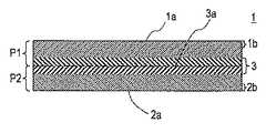
図1は、ナノファイバシートの繊維構造を説明するためのナノファイバシートの断面の概念図である。
図1に示されるように、ナノファイバシート1は、第1表面1aと、第1表面1aとは反対側の第2表面2aとを有しており、第1多孔質シートP1と第2多孔質シートP2とを貼り合わせた構造を有している。第1多孔質シートP1と、第2多孔質シートP2とは、基材シートの主面に接触していた表面同士を対向させて接合される。そのため、接合面3aの近傍(具体的には、ナノファイバシート1の厚さ方向の中心部)3では、繊維が少し押し潰された状態となっている。FIG. 1 is a conceptual diagram of a cross section of a nanofiber sheet for explaining the fiber structure of the nanofiber sheet.
As shown in FIG. 1, the nanofiber sheet 1 has a first surface 1a and a
一方、ナノファイバシート1の第1表面1aおよび第2表面2aは、基材シートと接触していない側の多孔質シートP1およびP2のそれぞれの表面に対応する。そのため、第1表面近傍1bおよび第2表面近傍2bでは、繊維が押し潰されていない。よって、ナノファイバのナノファイバシートの面方向における最大繊維径の平均を、第1表面近傍および第2表面近傍と、ナノファイバシートの厚さ方向の中心部とで比較したとき、第1表面近傍1aにおけるナノファイバの最大繊維径の平均Ds1および第2表面近傍におけるナノファイバの最大繊維径の平均Ds2は、ナノファイバシート1の接合面3aの近傍(具体的には、厚さ方向の中心部)3におけるナノファイバの最大繊維径の平均Dcより小さくなっている。 On the other hand, the first surface 1a and the
このように、ナノファイバシートは、その表面において、ナノファイバの、ナノファイバシートの面方向における最大繊維径の平均が小さくなっているため、高分子電解質を含浸させて、高分子電解質膜として用いてアノードおよびカソードと接触させた場合に、接触面積が大きくなるのを抑制することができる。これにより、接触面での電気抵抗の増加が抑制されるので、燃料電池の発電効率の低下を抑制できる。 Thus, since the average of the maximum fiber diameter of the nanofiber in the surface direction of the nanofiber sheet is small on the surface, the nanofiber sheet is impregnated with a polymer electrolyte and used as a polymer electrolyte membrane. Thus, it is possible to suppress an increase in the contact area when contacting with the anode and the cathode. Thereby, since the increase in the electrical resistance at the contact surface is suppressed, a decrease in the power generation efficiency of the fuel cell can be suppressed.
本発明において、高分子電解質膜の多孔質芯材として使用されるナノファイバシートは、両表面近傍の繊維が押し潰されていないため、ナノファイバシートとアノードおよびカソードとの接触面において、電気抵抗が大きくなるのを抑制できる。また、両表面近傍の繊維が押し潰されていないため、繊維間に多くの隙間が保持されていることに加え、ナノファイバシートは、一般に高い空隙率を有するため、空隙に多くの高分子電解質を保持することができる。 In the present invention, the nanofiber sheet used as the porous core material of the polymer electrolyte membrane has an electric resistance at the contact surface between the nanofiber sheet and the anode and cathode because the fibers near both surfaces are not crushed. Can be suppressed. In addition to the fact that the fibers in the vicinity of both surfaces are not crushed, many gaps are maintained between the fibers. In addition, since nanofiber sheets generally have a high porosity, many polymer electrolytes are present in the voids. Can be held.
高分子電解質では、電気抵抗を小さくするためには、通常、厚さを小さくする必要があるが、厚さが小さくなると、機械的強度が低下する。つまり、従来のナノファイバ不織布では、高い機械的強度を確保しながら、電気抵抗を低減することは難しい。 In the polymer electrolyte, in order to reduce the electrical resistance, it is usually necessary to reduce the thickness, but as the thickness decreases, the mechanical strength decreases. That is, it is difficult for conventional nanofiber nonwoven fabrics to reduce electrical resistance while ensuring high mechanical strength.
それに対し、本発明では、ナノファイバのマトリックス構造のために、厚さをそれほど大きくしなくとも高い機械的強度を確保できる。また、厚さを大きくする必要がないため、電気抵抗が大きくなるのを抑制できる。
さらに、不織布は、通常、空隙率が高いため、ピンホールが発生しやすくなる。しかし、本発明では、ナノファイバのマトリックス構造のために、ピンホールの発生を効果的に防止できる。On the other hand, in the present invention, due to the matrix structure of nanofibers, high mechanical strength can be ensured without increasing the thickness so much. Moreover, since it is not necessary to increase the thickness, it is possible to suppress an increase in electrical resistance.
Furthermore, since the nonwoven fabric has a high porosity, pinholes are likely to occur. However, the present invention can effectively prevent the generation of pinholes due to the nanofiber matrix structure.
「ナノファイバ」とは、ポリマーなどの高分子物質からなる繊維径50〜800nmの糸状物質を言う。
ナノファイバシートの面方向における最大繊維径とは、1本のナノファイバの繊維断面(繊維の幅方向の断面)を見たときに、ナノファイバシートの面方向における繊維幅のうち、最も大きなものを意味する。最大繊維径の平均とは、ナノファイバシートの厚さ方向の断面において、任意に選択した複数本(例えば、10本)のナノファイバの最大繊維径の平均値を意味する。なお、ナノファイバシートの面方向における最大繊維径を、単に、最大繊維径と称する場合がある。“Nanofiber” refers to a filamentous material having a fiber diameter of 50 to 800 nm made of a polymer material such as a polymer.
The maximum fiber diameter in the surface direction of the nanofiber sheet is the largest fiber width in the surface direction of the nanofiber sheet when the fiber cross section (cross section in the fiber width direction) of one nanofiber is viewed. Means. The average of the maximum fiber diameter means the average value of the maximum fiber diameters of a plurality of arbitrarily selected (for example, 10) nanofibers in the cross section in the thickness direction of the nanofiber sheet. Note that the maximum fiber diameter in the surface direction of the nanofiber sheet may be simply referred to as the maximum fiber diameter.
最大繊維径の平均Dcは、ナノファイバシートの厚さ方向の中心部を通る、ナノファイバシートの表面に平行な平面(または多孔質シートの接合面)近傍における、ナノファイバの最大繊維径の平均値を意味する。 The average maximum fiber diameter Dc is the average of the maximum fiber diameters of nanofibers in the vicinity of a plane parallel to the surface of the nanofiber sheet (or the bonding surface of the porous sheet) that passes through the center of the nanofiber sheet in the thickness direction. Mean value.
ナノファイバシートの厚さ方向の中心部とは、厚さ方向における中心または中心近傍に位置するのが好ましいが、必ずしも、中心または中心近傍に位置する必要はない。ナノファイバシートは、ナノファイバシートの内部に、ナノファイバの最大繊維径の平均がより大きい領域を有していればよい。例えば、ナノファイバシートの表面に平行な平面(または多孔質シートの接合面)を中心とするシート全体の厚さの10〜40%の厚さを有する領域に、ナノファイバの最大繊維径の平均がより大きい領域を含んでもよい。 The central portion of the nanofiber sheet in the thickness direction is preferably located at the center or near the center in the thickness direction, but is not necessarily located at the center or near the center. The nanofiber sheet should just have the area | region where the average of the largest fiber diameter of a nanofiber is larger inside a nanofiber sheet. For example, in a region having a thickness of 10 to 40% of the thickness of the entire sheet centering on a plane parallel to the surface of the nanofiber sheet (or a bonding surface of the porous sheet), the average of the maximum fiber diameters of the nanofibers May include larger regions.
なお、図1中の符号3で示されるような、ナノファイバシートの厚さ方向における中心部を通る、ナノファイバシートの表面に平行な平面近傍とは、例えば、この平面を中心とするシート全体の厚さの10〜30%の厚さを有する領域のことを意味する。
最大繊維径の平均Dcは、例えば、60nm〜2μm、好ましくは100nm〜1.2μm、さらに好ましくは200〜1000nmである。Note that the vicinity of a plane parallel to the surface of the nanofiber sheet passing through the center in the thickness direction of the nanofiber sheet as indicated by reference numeral 3 in FIG. 1 is, for example, the entire sheet centered on this plane. It means a region having a thickness of 10 to 30% of the thickness.
The average fiber diameter Dc is, for example, 60 nm to 2 μm, preferably 100 nm to 1.2 μm, and more preferably 200 to 1000 nm.
ナノファイバシートは、その両表面近傍において、ナノファイバの最大繊維径の平均Ds1およびDs2が比較的小さい。そのため、非常に細かな細孔が均一に形成されており、高分子電解質を含浸させて、高分子電解質膜として、アノードおよびカソードの間に介在させた場合に、界面における高分子電解質の分布が極めて均一になる。よって、どちらの電極に対しても、接触面における電気抵抗を低減できる。つまり、シートの両表面において、比較的一定の性質が得られやすいため、燃料電池の特性を安定化させ易くなる。 In the nanofiber sheet, the average Ds1 and Ds2 of the maximum fiber diameter of the nanofiber are relatively small in the vicinity of both surfaces. Therefore, very fine pores are uniformly formed, and when the polymer electrolyte is impregnated and interposed between the anode and the cathode as a polymer electrolyte membrane, the distribution of the polymer electrolyte at the interface is Extremely uniform. Therefore, the electrical resistance at the contact surface can be reduced for both electrodes. That is, since relatively constant properties are easily obtained on both surfaces of the sheet, the characteristics of the fuel cell are easily stabilized.
第1表面近傍におけるナノファイバの最大繊維径の平均Ds1は、第1表面近傍に存在するナノファイバの最大繊維径の平均値を意味する。同様に、第2表面近傍におけるナノファイバの最大繊維径の平均Ds2は、第2表面近傍に存在するナノファイバの最大繊維径の平均値を意味する。 The average maximum fiber diameter Ds1 of the nanofibers in the vicinity of the first surface means an average value of the maximum fiber diameters of the nanofibers in the vicinity of the first surface. Similarly, the average maximum fiber diameter Ds2 of the nanofibers in the vicinity of the second surface means an average value of the maximum fiber diameters of the nanofibers in the vicinity of the second surface.
なお、第1表面近傍とは、例えば、ナノファイバシートの第1表面からシート全体の厚さの10%の厚さを有する領域のことを意味する。同様に、第2表面近傍とは、例えば、ナノファイバシートの第2表面からシート全体の厚さの10%の厚さを有する領域のことを意味する。 Note that the vicinity of the first surface means, for example, a region having a thickness of 10% of the thickness of the entire sheet from the first surface of the nanofiber sheet. Similarly, the vicinity of the second surface means, for example, a region having a thickness of 10% of the thickness of the entire sheet from the second surface of the nanofiber sheet.
ナノファイバシートにおいて、最大繊維径の平均Ds1と、最大繊維径の平均Ds2とは、0.9≦Ds1/Ds2≦1.1を満たすのが好ましく、0.95≦Ds1/Ds2≦1.05を満たすのがさらに好ましい。Ds1およびDs2が、このような関係を満たす場合、ナノファイバシートの両表面の物性を、より均一にすることができるため、有利である。 In the nanofiber sheet, the average Ds1 of the maximum fiber diameter and the average Ds2 of the maximum fiber diameter preferably satisfy 0.9 ≦ Ds1 / Ds2 ≦ 1.1, and 0.95 ≦ Ds1 / Ds2 ≦ 1.05. It is more preferable to satisfy When Ds1 and Ds2 satisfy such a relationship, it is advantageous because the physical properties of both surfaces of the nanofiber sheet can be made more uniform.
最大繊維径の平均Ds1およびDs2は、それぞれ、例えば、50〜800nm、好ましくは60〜500nm、さらに好ましくは70〜200nmである。ナノファイバシートの両表面における最大繊維径の平均がこのような範囲である場合、高分子電解質を含浸させて、燃料電池の高分子電解質膜として用いた場合に、電極との接触面における電気抵抗を、より有効に低下させることができる。 The average Ds1 and Ds2 of the maximum fiber diameter are, for example, 50 to 800 nm, preferably 60 to 500 nm, and more preferably 70 to 200 nm, respectively. When the average of the maximum fiber diameters on both surfaces of the nanofiber sheet is within such a range, when the polymer electrolyte is impregnated and used as a polymer electrolyte membrane of a fuel cell, the electrical resistance at the contact surface with the electrode Can be reduced more effectively.
Ds1およびDcは、例えば、1.1≦Dc/Ds1≦2.5、好ましくは1.2≦Dc/Ds1≦2.2、さらに好ましくは1.3≦Dc/Ds1≦2の関係を充足する。また、Ds2およびDcは、例えば、1.1≦Dc/Ds2≦2.5、好ましくは1.2≦Dc/Ds1≦2.2、さらに好ましくは1.3≦Dc/Ds1≦2の関係を充足する。ナノファイバシートが、このような最大繊維径の関係を満たす場合、高分子電解質を含浸させて高分子電解質膜として用いた場合に、電極との接触抵抗を、より有効に低下させることができる。 For example, Ds1 and Dc satisfy the relationship of 1.1 ≦ Dc / Ds1 ≦ 2.5, preferably 1.2 ≦ Dc / Ds1 ≦ 2.2, and more preferably 1.3 ≦ Dc / Ds1 ≦ 2. . Ds2 and Dc have a relationship of, for example, 1.1 ≦ Dc / Ds2 ≦ 2.5, preferably 1.2 ≦ Dc / Ds1 ≦ 2.2, more preferably 1.3 ≦ Dc / Ds1 ≦ 2. Satisfy. When the nanofiber sheet satisfies such a maximum fiber diameter relationship, the contact resistance with the electrode can be more effectively reduced when the nanofiber sheet is impregnated with a polymer electrolyte and used as a polymer electrolyte membrane.
ナノファイバシートの平均の空隙率Pは、例えば、50〜95%、好ましくは60〜92%、さらに好ましくは70〜90%である。
ナノファイバシートにおいて、第1表面近傍における空隙率Ps1と、第2表面近傍における空隙率Ps2とは、0.9≦Ps1/Ps2≦1.1を満たすのが好ましく、0.95≦Ps1/Ps2≦1.05を満たすのがさらに好ましい。Ps1およびPs2がこのような関係を満たす場合、ナノファイバシートの両表面の物性を、より均一にすることができるため、有利である。The average porosity P of the nanofiber sheet is, for example, 50 to 95%, preferably 60 to 92%, and more preferably 70 to 90%.
In the nanofiber sheet, the porosity Ps1 in the vicinity of the first surface and the porosity Ps2 in the vicinity of the second surface preferably satisfy 0.9 ≦ Ps1 / Ps2 ≦ 1.1, and 0.95 ≦ Ps1 / Ps2 More preferably, ≦ 1.05 is satisfied. When Ps1 and Ps2 satisfy such a relationship, it is advantageous because the physical properties of both surfaces of the nanofiber sheet can be made more uniform.
第1および第2多孔質シートの厚さがほぼ同じである場合には、接合面は、ナノファイバシートの厚さ方向における中心に位置する。接合面は、必ずしも、ナノファイバシートの厚さ方向における中心に位置している必要はないが、中心またはその近傍に位置しているのが好ましい。 When the thicknesses of the first and second porous sheets are substantially the same, the bonding surface is located at the center in the thickness direction of the nanofiber sheet. The bonding surface is not necessarily located at the center in the thickness direction of the nanofiber sheet, but is preferably located at or near the center.
ナノファイバシートは、多孔質シートの接合面またはナノファイバシートの厚さ方向の中心部分を境界にして対称な構造とする必要はないが、対称な構造を有するのが好ましい。具体的には、ナノファイバシートの厚さ方向の中心(具体的には、この中心を通り、かつナノファイバシートの表面に平行な平面)を境界にして、ナノファイバシートを、第1表面側の第1領域と、第2表面側の第2領域とに区分するとき、第1領域および第2領域を、上記境界に対して対称な構造を有することが好ましい。このような構造を有するナノファイバシートでは、第1表面側と、第2表面側とで、物性をより均一化することができる。 The nanofiber sheet does not need to have a symmetric structure with the joint surface of the porous sheet or the central portion in the thickness direction of the nanofiber sheet as a boundary, but preferably has a symmetric structure. Specifically, the nanofiber sheet is placed on the first surface side with the center in the thickness direction of the nanofiber sheet (specifically, a plane passing through the center and parallel to the surface of the nanofiber sheet) as a boundary. When the first region and the second region on the second surface side are divided, it is preferable that the first region and the second region have a symmetric structure with respect to the boundary. In the nanofiber sheet having such a structure, physical properties can be made more uniform on the first surface side and the second surface side.
ナノファイバシートは、ナノファイバのマトリックス構造を有しており、通常、不織布の形態である。
ナノファイバシートのマトリックス構造において、ナノファイバ同士は、接点において、互いに接着した状態であってもよく、接着することなく分離していてもよい。ナノファイバ同士は、マトリックス構造中、ランダムに接着していてもよい。The nanofiber sheet has a nanofiber matrix structure and is usually in the form of a nonwoven fabric.
In the matrix structure of the nanofiber sheet, the nanofibers may be bonded to each other at the contact points, or may be separated without bonding. The nanofibers may be bonded at random in the matrix structure.
また、必要に応じて、ナノファイバのマトリックス構造に、ポリマーなどのバインダーを含む溶液を含浸や塗布などにより適用し、あるいは、ナノファイバの原料に含ませて、ナノファイバ同士を、バインダーで接着させてもよい。
ナノファイバシートでは、両表面の近傍よりも、厚さ方向の中心部近傍において、ナノファイバ同士の接着が多くなっていてもよい。In addition, if necessary, a solution containing a binder such as a polymer is applied to the nanofiber matrix structure by impregnation or coating, or the nanofiber raw material is bonded to the nanofibers with a binder. May be.
In the nanofiber sheet, the adhesion between the nanofibers may be greater in the vicinity of the central portion in the thickness direction than in the vicinity of both surfaces.
電界紡糸法において、ナノファイバは、ポリマー溶液や溶融ポリマーを紡糸することにより形成される。そのため、ナノファイバ同士の接着は、ナノファイバ同士の溶着や融着であってもよい。 In the electrospinning method, the nanofiber is formed by spinning a polymer solution or a molten polymer. Therefore, the adhesion between the nanofibers may be welding or fusion between the nanofibers.
ポリマー溶液を用いた電界紡糸では、溶媒が完全に揮発せずに溶媒に膨潤した状態のナノファイバが堆積すると、接点において、溶媒の作用により、ナノファイバ同士が相溶し、溶媒が揮発した後は、ナノファイバ同士が溶着した状態となる。
溶融ポリマーを用いた電界紡糸では、ナノファイバが堆積する際に、完全に固化していないナノファイバ同士が接触した状態で固化すると、接点において、ナノファイバ同士が融着した状態となる。In electrospinning using a polymer solution, when the nanofibers in a swollen state are deposited in the solvent without the solvent completely evaporating, the nanofibers are compatible with each other by the action of the solvent at the contact point, and the solvent is volatilized. Is a state in which the nanofibers are welded to each other.
In electrospinning using a molten polymer, when nanofibers are deposited, if nanofibers that are not completely solidified are solidified in contact with each other, the nanofibers are fused at the contact points.
ナノファイバを構成するポリマー(または樹脂原料)などの高分子物質の種類は、電界紡糸可能である限り、特に制限されず、溶融可能な各種熱可塑性ポリマーや、溶媒に溶解可能なポリマーなどが例示できる。 The type of polymer material such as polymer (or resin raw material) constituting the nanofiber is not particularly limited as long as it can be electrospun, and examples include various thermoplastic polymers that can be melted and polymers that can be dissolved in a solvent. it can.
このようなポリマーとしては、例えば、オレフィン樹脂(例えば、エチレンおよび/またはプロピレンなどをモノマー単位として含む単独重合体または共重合体);ビニル樹脂(ポリ酢酸ビニル、エチレン−酢酸ビニル共重合体などの酢酸ビニル樹脂またはそのケン化物(ポリビニルアルコールまたはその変性体など);ポリスチレン、スチレンをモノマー単位として含む共重合体などの芳香族ビニル樹脂;ポリアクリロニトリルなどのシアン化ビニル樹脂など);アクリル樹脂(ポリメチルメタクリレートなどのアクリル酸エステルやメタクリル酸エステルをモノマー単位として含む単独重合体または共重合体など);フッ素樹脂;ポリエステル樹脂(ポリ乳酸、ポリカプロラクトンなどの脂肪族ポリエステル、芳香族ポリエステルなど);ポリアミド樹脂;ポリイミド樹脂;ポリアリーレンエーテル樹脂(ポリフェニレンエーテルなど);ポリアリーレンスルフィド樹脂(ポリフェニレンスルフィド、ポリフェニレンスルフィドスルホンなど);ポリエーテルケトン樹脂(ポリエーテルケトン、ポリエーテルエーテルケトンなど);セルロース誘導体(セルロースエステル、セルロースエーテルなど);生分解性ポリマーなどのバイオポリマー;シリコーン樹脂などが挙げられる。 Examples of such polymers include olefin resins (for example, homopolymers or copolymers containing ethylene and / or propylene as monomer units); vinyl resins (polyvinyl acetate, ethylene-vinyl acetate copolymers, etc.) Vinyl acetate resin or a saponified product thereof (polyvinyl alcohol or a modified product thereof); Aromatic vinyl resin such as a copolymer containing polystyrene or styrene as a monomer unit; Vinyl cyanide resin such as polyacrylonitrile; Homopolymer or copolymer containing acrylic acid ester or methacrylic acid ester as a monomer unit such as methyl methacrylate); Fluororesin; Polyester resin (aliphatic polyester such as polylactic acid or polycaprolactone, aromatic polyester, etc.) Polyamide resin; Polyimide resin; Polyarylene ether resin (such as polyphenylene ether); Polyarylene sulfide resin (such as polyphenylene sulfide and polyphenylene sulfide sulfone); Polyether ketone resin (such as polyether ketone and polyether ether ketone); Cellulose derivative (cellulose) Ester, cellulose ether, etc.); biopolymers such as biodegradable polymers; silicone resins and the like.
上記のポリマーは、一種を単独でまたは二種以上を組み合わせて使用できる。
上記のポリマーのうち、特に、オレフィン樹脂、ビニル樹脂(酢酸ビニル樹脂またはそのケン化物など)、フッ素樹脂、ポリアミド樹脂、ポリイミド樹脂が好ましい。Said polymer can be used individually by 1 type or in combination of 2 or more types.
Of the above polymers, olefin resin, vinyl resin (vinyl acetate resin or saponified product thereof), fluorine resin, polyamide resin, and polyimide resin are particularly preferable.
フッ素樹脂としては、ポリテトラフルオロエチレン(PTFE)、テトラフルオロエチレン−ヘキサフルオロプロピレン共重合体(FEP)、テトラフルオロエチレン−パーフルオロアルキルビニルエーテル共重合体(PFA)、テトラフルオロエチレン−エチレン共重合体、ポリビニリデンフルオライド(PVDF)、ポリビニルフルオライド(PVF)などのフッ素含有モノマー単位を有する単独重合体または共重合体が例示できる。 Examples of fluororesins include polytetrafluoroethylene (PTFE), tetrafluoroethylene-hexafluoropropylene copolymer (FEP), tetrafluoroethylene-perfluoroalkyl vinyl ether copolymer (PFA), and tetrafluoroethylene-ethylene copolymer. Examples thereof include homopolymers and copolymers having fluorine-containing monomer units such as polyvinylidene fluoride (PVDF) and polyvinyl fluoride (PVF).
ポリアミド樹脂としては、ポリアミド6、ポリアミド6−12などの脂肪族ポリアミド;脂環族ポリアミド;ポリアミドMDX−6、アラミドなどの芳香族ポリアミドなどが例示できる。芳香族ポリアミド、特に、アラミドなどの全芳香族ポリアミドが好ましい。 Examples of the polyamide resin include aliphatic polyamides such as polyamide 6 and polyamide 6-12; alicyclic polyamides; aromatic polyamides such as polyamide MDX-6 and aramid. Aromatic polyamides, particularly wholly aromatic polyamides such as aramid, are preferred.
ポリイミド樹脂は、例えば、ポリアミド酸から得られる縮合型ポリイミド、ビスマレイミド樹脂などの熱硬化性ポリイミド;熱可塑性ポリイミドが挙げられる。熱可塑性ポリイミドとしては、例えば、ベンゾフェノンテトラカルボン酸およびジアミノジフェニルメタンをモノマー単位として含むポリイミド、ポリエーテルイミド、ポリアミドイミド、ポリエステルイミドなどが例示できる。
ナノファイバは、必要に応じて、ポリマー以外に、公知の添加剤を含んでもよい。添加剤の含有量は、例えば、ナノファイバシートの5質量%以下である。Examples of the polyimide resin include thermosetting polyimides such as condensation type polyimides and bismaleimide resins obtained from polyamic acid; and thermoplastic polyimides. Examples of the thermoplastic polyimide include polyimide, polyether imide, polyamide imide, and polyester imide that include benzophenone tetracarboxylic acid and diaminodiphenylmethane as monomer units.
A nanofiber may contain a well-known additive other than a polymer as needed. The content of the additive is, for example, 5% by mass or less of the nanofiber sheet.
ナノファイバシートの厚さは、例えば、5〜200μm、好ましくは10〜100μmまたは15〜70μmである。 The thickness of the nanofiber sheet is, for example, 5 to 200 μm, preferably 10 to 100 μm or 15 to 70 μm.
(高分子電解質)
高分子電解質膜は、多孔質芯材としてのナノファイバシートと、ナノファイバシートに含浸させた高分子電解質とを含む。
高分子電解質としては、イオン交換樹脂などが使用できる。イオン交換樹脂としては、例えば、燃料電池の分野で常用される材料を特に限定することなく用いることができる。(Polymer electrolyte)
The polymer electrolyte membrane includes a nanofiber sheet as a porous core material and a polymer electrolyte impregnated in the nanofiber sheet.
An ion exchange resin or the like can be used as the polymer electrolyte. As the ion exchange resin, for example, a material commonly used in the field of fuel cells can be used without any particular limitation.
イオン交換樹脂には、酸性基、塩基性基などのイオン交換基を有するプロトン伝導性の高分子が含まれる。酸性基を有する高分子電解質としては、スルホン酸基、ホスホン酸基、リン酸基などの強酸性基を有する陽イオン交換樹脂を使用するのが好ましい。塩基性基を有する高分子電解質としては、4級アンモニウム塩基を有する強塩基性陰イオン交換樹脂の他、1級、2級または3級アミノ基を有する弱塩基性陰イオン交換樹脂、例えば、ポリベンズイミダゾール、ベンズイミダゾール−ポリイミド共重合体などのベンズイミダゾールユニットを有する単独重合体または共重合体;アミノ化ポリエーテルスルホンなどが例示できる。 The ion exchange resin includes a proton conductive polymer having an ion exchange group such as an acidic group or a basic group. As the polymer electrolyte having an acidic group, it is preferable to use a cation exchange resin having a strongly acidic group such as a sulfonic acid group, a phosphonic acid group, or a phosphoric acid group. Examples of the polymer electrolyte having a basic group include a strongly basic anion exchange resin having a quaternary ammonium base, and a weakly basic anion exchange resin having a primary, secondary or tertiary amino group, such as a polyelectrolyte. Examples thereof include homopolymers or copolymers having a benzimidazole unit such as benzimidazole and benzimidazole-polyimide copolymer; aminated polyethersulfone and the like.
イオン交換樹脂は、例えば、イオン交換基を有する単量体の単独又は共重合体の他、樹脂(例えば、芳香環ユニットを有する樹脂など)にイオン交換基を導入することにより得られる樹脂であってもよい。
イオン交換樹脂は、一種を単独で又は二種以上を組み合わせて使用できる。The ion exchange resin is, for example, a resin obtained by introducing an ion exchange group into a resin (for example, a resin having an aromatic ring unit) in addition to a monomer having an ion exchange group or a copolymer. May be.
An ion exchange resin can be used individually by 1 type or in combination of 2 or more types.
具体的には、イオン交換樹脂として、イオン交換基としてスルホン酸基を有するイオン交換樹脂、例えば、パーフルオロスルホニルアルキル基を側鎖に含む樹脂(パーフルオロスルホン酸系樹脂)、およびスルホン化ポリマーを好ましく使用できる。 Specifically, as an ion exchange resin, an ion exchange resin having a sulfonic acid group as an ion exchange group, for example, a resin containing a perfluorosulfonylalkyl group in a side chain (perfluorosulfonic acid resin), and a sulfonated polymer It can be preferably used.
パーフルオロスルホン酸系樹脂としては、例えば、Nafion(登録商標)、Flemion(登録商標)等のパーフルオロスルホニルアルキル基を側鎖に含むフルオロアルキレンユニットを含む単独重合体または共重合体などが挙げられる。 Examples of the perfluorosulfonic acid resin include homopolymers or copolymers containing a fluoroalkylene unit containing a perfluorosulfonylalkyl group in the side chain, such as Nafion (registered trademark) and Flemion (registered trademark). .
スルホン化ポリマーは、ポリマーの主鎖または側鎖に、スルホン化によりスルホン酸基が導入されたポリマーであり、本明細書では、側鎖にパーフルオロスルホニルアルキル基を含まないものとして分類する。 The sulfonated polymer is a polymer in which a sulfonic acid group is introduced into the main chain or side chain of the polymer by sulfonation, and in this specification, it is classified as not containing a perfluorosulfonylalkyl group in the side chain.
スルホン化ポリマーとしては、例えば、スルホン化スチレン樹脂(スルホン化スチレン−ジビニルベンゼン共重合体など)、スルホン化ポリエーテルケトン系樹脂(スルホン化ポリエーテルケトン、スルホン化ポリエーテルエーテルケトンなど)、スルホン化ポリスルホン系樹脂(スルホン化ポリスルホン、スルホン化ポリエーテルスルホン、スルホン化ポリエーテルエーテルスルホンなど)、スルホン化ポリイミド樹脂(スルホン化ポリイミドなど)などが挙げられる。 Examples of the sulfonated polymer include a sulfonated styrene resin (sulfonated styrene-divinylbenzene copolymer, etc.), a sulfonated polyether ketone resin (sulfonated polyether ketone, sulfonated polyether ether ketone, etc.), and sulfonated. Examples thereof include polysulfone resins (sulfonated polysulfone, sulfonated polyethersulfone, sulfonated polyetherethersulfone, etc.), sulfonated polyimide resins (sulfonated polyimide, etc.), and the like.
高分子電解質膜は、後述するように、ナノファイバシートに高分子電解質を含浸させることにより得られる。
高分子電解質膜に含まれる高分子電解質の割合は、ナノファイバシート100質量部に対して、例えば、1〜100質量部、好ましくは5〜50質量部、さらに好ましくは7〜30質量部である。The polymer electrolyte membrane is obtained by impregnating a nanofiber sheet with a polymer electrolyte, as will be described later.
The ratio of the polymer electrolyte contained in the polymer electrolyte membrane is, for example, 1 to 100 parts by mass, preferably 5 to 50 parts by mass, and more preferably 7 to 30 parts by mass with respect to 100 parts by mass of the nanofiber sheet. .
[高分子電解質型燃料電池]
上記の高分子電解質膜は、アノードおよびカソードの間に介在させて、膜電極接合体を形成し、高分子電解質型燃料電池に使用される。膜電極接合体は、上記の高分子電解質膜と、高分子電解質膜の一方の表面に形成されたアノードと、高分子電解質膜の他方の表面に形成されたカソードと、を具備する。[Polymer electrolyte fuel cell]
The polymer electrolyte membrane is interposed between an anode and a cathode to form a membrane electrode assembly and is used for a polymer electrolyte fuel cell. The membrane electrode assembly includes the above-described polymer electrolyte membrane, an anode formed on one surface of the polymer electrolyte membrane, and a cathode formed on the other surface of the polymer electrolyte membrane.
高分子電解質型燃料電池は、上記の膜電極接合体と、アノードに接触するとともに、アノードに燃料を供給する燃料流路を有するアノード側セパレータと、カソードに接触するとともに、カソードに酸化剤を供給するカソード側セパレータと、を具備する。 The polymer electrolyte fuel cell is in contact with the membrane electrode assembly described above, an anode, an anode separator having a fuel flow path for supplying fuel to the anode, a cathode, and an oxidant supplied to the cathode. A cathode-side separator.
以下、本発明の膜電極接合体およびそれを用いた高分子電解質型燃料電池を、図面を参照しながら説明する。図2は、本発明の一実施形態に係る高分子電解質型燃料電池の構成を概略的に示す縦断面図である。 Hereinafter, a membrane electrode assembly of the present invention and a polymer electrolyte fuel cell using the same will be described with reference to the drawings. FIG. 2 is a longitudinal sectional view schematically showing a configuration of a polymer electrolyte fuel cell according to an embodiment of the present invention.
図2の燃料電池11は、1つの単位セルからなる。単位セルは、高分子電解質膜110と、高分子電解質膜110を挟むアノード111およびカソード112とからなる膜電極接合体(MEA)113、ならびにMEA113を挟むアノード側セパレータ114およびカソード側セパレータ115を備える。 The
カソード112は、高分子電解質膜110に接触するカソード触媒層118と、カソード触媒層118に積層されたカソード拡散層119とを含む。カソード拡散層119は、カソード触媒層118に接触する多孔質撥水層と、多孔質撥水層に積層され、カソード側セパレータと接触する多孔質基材層とを含む。 The
アノード111は、高分子電解質膜110に接触するアノード触媒層116と、アノード触媒層116に積層されたアノード拡散層117とを含む。アノード拡散層117は、アノード触媒層116に接触する多孔質撥水層と、多孔質撥水層に積層され、アノード側セパレータ114と接触する多孔質基材層とを含む。 The
アノード側セパレータ114は、アノード111と対向する面に、アノードに燃料を供給し、未使用燃料および反応生成物(例えば、二酸化炭素)を排出する流路120を有する。カソード側セパレータ115は、カソード112と対向する面に、カソードに酸化剤を供給し、未使用酸化剤および反応生成物を排出する流路121を有する。酸化剤としては、例えば、酸素ガス、または空気のような酸素ガスを含む混合ガスが用いられる。通常は、空気を酸化剤として用いる。 The anode-
アノード111の周囲には、アノード111を封止するように、アノード側ガスケット122が配置されている。同様に、カソード112の周囲には、カソード112を封止するように、カソード側ガスケット123が配置されている。アノード側ガスケット122とカソード側ガスケット123とは、高分子電解質膜110を介して対向している。アノード側ガスケット122およびカソード側ガスケット123により、燃料、酸化剤、および反応生成物が外部へ漏洩することが防止される。 An
さらに、図2の燃料電池11は、アノード側セパレータ114およびカソード側セパレータ115の面方向と垂直な方向に積層される、集電板124および125、シート状のヒータ126および127、絶縁板128および129、ならびに端板130および131を有する。燃料電池11のこれらの要素は、締結手段(図示せず)により一体化されている。 Further, the
カソード拡散層119およびアノード拡散層117に含まれる多孔質基材層としては、例えば、多孔質でシート状の炭素材料を用いることができ、具体的には、カーボンペーパー、カーボンクロス、カーボン不織布などが挙げられる。
多孔質基材層の厚さは、例えば、100〜500μm、好ましくは150〜350μmである。多孔質基材層の空隙率は、例えば70〜90%である。As the porous base material layer included in the cathode diffusion layer 119 and the anode diffusion layer 117, for example, a porous and sheet-like carbon material can be used. Specifically, carbon paper, carbon cloth, carbon non-woven fabric, etc. Is mentioned.
The thickness of the porous substrate layer is, for example, 100 to 500 μm, preferably 150 to 350 μm. The porosity of the porous substrate layer is, for example, 70 to 90%.
多孔質基材層には、撥水性材料を付着させてもよい。撥水性材料としては、例えば、前記ナノファイバを構成するポリマーの項で例示したフッ素樹脂などが挙げられる。 A water repellent material may be attached to the porous substrate layer. Examples of the water repellent material include the fluororesins exemplified in the section of the polymer constituting the nanofiber.
多孔質撥水層は、導電性炭素材料および撥水性樹脂材料を含む。導電性炭素材料としては、例えば、カーボンブラック、黒鉛、カーボン繊維などが挙げられる。撥水性樹脂材料としては、前記ナノファイバを構成するポリマーの項で例示したフッ素樹脂などが例示できる。
多孔質撥水層の平均厚さは、例えば、20〜70μm、好ましくは20〜30μmである。The porous water repellent layer includes a conductive carbon material and a water repellent resin material. Examples of the conductive carbon material include carbon black, graphite, and carbon fiber. Examples of the water-repellent resin material include the fluororesins exemplified in the section of the polymer constituting the nanofiber.
The average thickness of the porous water repellent layer is, for example, 20 to 70 μm, preferably 20 to 30 μm.
カソード触媒層118およびアノード触媒層116は、それぞれ、触媒金属微粒子および高分子電解質を含む。カソード触媒層用の触媒金属としては、例えば、Ptや、Pt−Co合金などを用いることができる。アノード触媒層用の触媒金属としては、例えば、Pt−Ru合金などを用いることができる。 The cathode catalyst layer 118 and the anode catalyst layer 116 include catalyst metal fine particles and a polymer electrolyte, respectively. As the catalyst metal for the cathode catalyst layer, for example, Pt, a Pt—Co alloy, or the like can be used. As the catalyst metal for the anode catalyst layer, for example, a Pt—Ru alloy or the like can be used.
触媒金属微粒子は、単独で用いてもよく、担体に担持してもよい。担体としては、例えば、カーボンブラックなどの導電性炭素材料が例示できる。 The catalytic metal fine particles may be used alone or may be supported on a carrier. Examples of the carrier include conductive carbon materials such as carbon black.
カソード触媒層118およびアノード触媒層116に含まれる高分子電解質としては、高分子電解質膜の項で例示した高分子電解質が使用でき、イオン交換基としてスルホン酸記を有するイオン交換樹脂などが好ましい。 As the polymer electrolyte contained in the cathode catalyst layer 118 and the anode catalyst layer 116, the polymer electrolyte exemplified in the section of the polymer electrolyte membrane can be used, and an ion exchange resin having sulfonic acid as an ion exchange group is preferable.
触媒層における高分子電解質の含有量は、例えば、15〜35質量%、好ましくは18〜30質量%である。カソード触媒層およびアノード触媒層に含まれる高分子電解質は、互いに、同じであってもよく、異なってもよい。高分子電解質膜を構成する高分子電解質と、カソード触媒層およびアノード触媒層に含まれる高分子電解質とは、同じであってもよく、異なっていてもよい。 The content of the polymer electrolyte in the catalyst layer is, for example, 15 to 35% by mass, preferably 18 to 30% by mass. The polymer electrolytes contained in the cathode catalyst layer and the anode catalyst layer may be the same as or different from each other. The polymer electrolyte constituting the polymer electrolyte membrane and the polymer electrolyte contained in the cathode catalyst layer and the anode catalyst layer may be the same or different.
カソード側セパレータ115およびアノード側セパレータ114は、気密性、電子伝導性および電気化学的安定性を有すればよく、その材質は、特に限定されない。また、流路120および121の形状についても特に限定されず、例えば、サーペンタイン型、パラレル型等が挙げられる。 The cathode side separator 115 and the
カソード側セパレータは、カソード拡散層との接触面に、カソードに酸化剤(空気)を供給するための酸化剤流路を有している。酸化剤流路も、例えば、上記接触面に形成され、カソード拡散層に向かって開口する凹部ないしは溝から構成される。酸化剤流路は、燃料電池本体の酸化剤入口および酸化剤出口と連絡している。 The cathode side separator has an oxidant channel for supplying an oxidant (air) to the cathode on the contact surface with the cathode diffusion layer. The oxidant flow path is also formed of, for example, a recess or groove formed on the contact surface and opening toward the cathode diffusion layer. The oxidant flow path communicates with the oxidant inlet and the oxidant outlet of the fuel cell main body.
アノード側セパレータは、アノード拡散層との接触面に、アノードに燃料を供給するための燃料流路を有している。燃料流路は、例えば、上記接触面に形成され、アノード拡散層に向かって開口する凹部ないしは溝から構成される。燃料流路は、燃料電池本体の燃料入口および燃料出口と連絡している。
カソード側セパレータおよびアノード側セパレータは、一方の面に燃料流路を有し、他方の面に酸化剤流路を有するように一体に形成してもよく、それぞれを単独に形成してもよい。The anode separator has a fuel flow path for supplying fuel to the anode on the contact surface with the anode diffusion layer. The fuel flow path is formed of, for example, a recess or groove formed on the contact surface and opening toward the anode diffusion layer. The fuel flow path communicates with the fuel inlet and the fuel outlet of the fuel cell main body.
The cathode side separator and the anode side separator may be integrally formed so as to have a fuel flow path on one surface and an oxidant flow path on the other surface, or each may be formed independently.
集電板124および125、シート状のヒータ126および127、絶縁板128および129、ならびに端板130および131には、当該分野で公知のものを用いることができる。
燃料としては、特に制限されず、例えば、メタノールなどを用いることができる。As the
The fuel is not particularly limited, and for example, methanol can be used.
MEAは、公知の方法により製造できる。例えば、(i)高分子電解質膜の一方の表面にカソード触媒層を、他方の表面にアノード触媒層を、それぞれ形成することにより、膜−触媒層接合体(CCM)を得、(ii)カソード多孔質基材層の一方の表面にカソード多孔質撥水層を、アノード多孔質基材層の一方の表面にアノード多孔質撥水層を、それぞれ、形成することにより、カソード拡散層およびアノード拡散層を形成し、(iii)CCMの一方の表面にカソード拡散層を、他方の表面にアノード拡散層を、それぞれ、触媒層と、多孔質撥水層とが接触するように積層し、得られた積層体を接合することにより、高分子電解質膜がカソードおよびアノードで挟持されたMEAを得ることができる。 MEA can be produced by a known method. For example, (i) a cathode catalyst layer is formed on one surface of a polymer electrolyte membrane, and an anode catalyst layer is formed on the other surface to obtain a membrane-catalyst layer assembly (CCM), and (ii) a cathode By forming a cathode porous water repellent layer on one surface of the porous substrate layer and an anode porous water repellent layer on one surface of the anode porous substrate layer, respectively, the cathode diffusion layer and anode diffusion layer are formed. (Iii) a cathode diffusion layer on one surface of the CCM and an anode diffusion layer on the other surface are laminated so that the catalyst layer and the porous water-repellent layer are in contact with each other. By joining the laminated bodies, an MEA in which the polymer electrolyte membrane is sandwiched between the cathode and the anode can be obtained.
各層は、構成成分を含むペーストをベースとなる層に塗布し、乾燥することにより形成できる。各層を形成する際に、必要に応じて、適宜加熱してもよい。積層体の接合は、例えば、ホットプレス法などにより行うことができる。 Each layer can be formed by applying a paste containing a constituent component to a base layer and drying. When forming each layer, you may heat suitably as needed. The laminates can be joined by, for example, a hot press method.
高分子電解質型燃料電池は、公知の方法により製造できる。例えば、上記のMEAのアノードおよびカソードの周囲に、アノード側ガスケットおよびカソード側ガスケットを、高分子電解質膜を挟み込むように配置し、さらにアノード側セパレータおよびカソード側セパレータ、集電板、シート状のヒータ、絶縁板、ならびに端板で両側から挟み込み、締結ロッドで固定することにより、高分子電解質型燃料電池を得ることができる。 The polymer electrolyte fuel cell can be manufactured by a known method. For example, an anode side gasket and a cathode side gasket are arranged around the anode and cathode of the above MEA so as to sandwich a polymer electrolyte membrane, and further, an anode side separator and a cathode side separator, a current collector plate, a sheet heater Then, the polymer electrolyte fuel cell can be obtained by sandwiching from both sides with the insulating plate and the end plate and fixing with the fastening rod.
MEAおよびこれを用いた高分子電解質型燃料電池に使用される、高分子電解質膜の製造方法の詳細について、以下に説明する。 Details of a method for producing a polymer electrolyte membrane used in MEA and a polymer electrolyte fuel cell using the same will be described below.
[高分子電解質膜の製造方法]
高分子電解質膜は、ナノファイバシート(多孔質芯材)を準備する工程と、ナノファイバシートに高分子電解質を含浸させる工程とを経ることにより製造できる。例えば、製造ラインの上流側でナノファイバシートを準備し、下流側で、ナノファイバシートに高分子電解質を含浸させることにより、高分子電解質膜を製造してもよい。[Production method of polymer electrolyte membrane]
The polymer electrolyte membrane can be manufactured through a step of preparing a nanofiber sheet (porous core material) and a step of impregnating the nanofiber sheet with the polymer electrolyte. For example, the polymer electrolyte membrane may be manufactured by preparing a nanofiber sheet on the upstream side of the production line and impregnating the nanofiber sheet with the polymer electrolyte on the downstream side.
ナノファイバシートへの高分子電解質の含浸は、例えば、高分子電解質を溶媒に溶解させた溶液にナノファイバシートを浸漬したり、ナノファイバシートに前記溶液を塗布または噴霧したりすることにより行うことができる。高分子電解質を含浸させたナノファイバシートは、通常、乾燥される。 The nanofiber sheet is impregnated with the polymer electrolyte by, for example, immersing the nanofiber sheet in a solution obtained by dissolving the polymer electrolyte in a solvent, or applying or spraying the solution onto the nanofiber sheet. Can do. The nanofiber sheet impregnated with the polymer electrolyte is usually dried.
上記溶液の溶媒としては、高分子電解質を可溶である限りその種類は特に限定されず、種々の溶媒が使用できる。溶媒としては、例えば、ジメチルホルムアミドなどのアミド;ジメチルスルホキシドなどのスルホキシド、N−メチル−2−ピロリドンなどの非プロトン性極性溶媒が好ましい。 The solvent of the solution is not particularly limited as long as the polymer electrolyte is soluble, and various solvents can be used. As the solvent, for example, an amide such as dimethylformamide; a sulfoxide such as dimethyl sulfoxide; and an aprotic polar solvent such as N-methyl-2-pyrrolidone are preferable.
高分子電解質の含浸に供されるナノファイバシートは、次のようにして準備される。
ナノファイバシートは、電界紡糸法により、基材シートの主面にナノファイバを堆積させて多孔質シートを形成する工程(A)と、一対の多孔質シートの基材シートの主面と接触していた表面同士を対向させて接合する工程(B)とを経ることにより製造できる。
ナノファイバシートの製造方法は、さらに、工程(A)に先だって、基材シートを、ナノファイバを形成させる空間(ナノファイバ形成空間)に配置または供給する工程(a)、および/または、工程(B)の後に、完成したシートを回収する工程(C)を有していてもよい。A nanofiber sheet to be impregnated with the polymer electrolyte is prepared as follows.
The nanofiber sheet is in contact with the main surface of the base sheet of the pair of porous sheets by the step (A) of forming a porous sheet by depositing nanofibers on the main surface of the base sheet by an electrospinning method. It can manufacture by passing through the process (B) which makes the surfaces which faced face each other and join.
In addition to the step (A), the method for producing a nanofiber sheet further includes the step (a) of arranging or supplying the base sheet in a space (nanofiber formation space) in which nanofibers are formed and / or the step ( You may have the process (C) which collects the completed sheet | seat after B).
工程(a)では、ラインの上流側から、ナノファイバ形成空間に、長尺の基材シートを搬送してもよい。第1および第2多孔質シートからなる一対の多孔質シートを工程(A)で形成するために、工程(a)では、例えば、第1および第2ラインの上流から下流にそれぞれ長尺の第1および第2基材シートを搬送してもよい。また、工程(A)において、ラインの上流側で、第1および第2基材シートの主面にそれぞれ第1および第2多孔質シートを形成し、工程(B)において、ラインの下流側で、第1および第2多孔質シートを対向させて接合してもよい。 In the step (a), a long base sheet may be conveyed from the upstream side of the line to the nanofiber formation space. In order to form a pair of porous sheets composed of the first and second porous sheets in the step (A), in the step (a), for example, the long first from the upstream to the downstream of the first and second lines, respectively. You may convey the 1st and 2nd base material sheet. In the step (A), the first and second porous sheets are respectively formed on the main surfaces of the first and second base sheets on the upstream side of the line. In the step (B), on the downstream side of the line The first and second porous sheets may be joined to face each other.
多孔質シートの基材シートの主面と接触していた表面は、基材シートの主面の形状が転写されて、少し押し潰され、繊維が平らな状態となっている。また、このような状態の表面同士を対向させて一対の多孔質シートを接合することにより、得られるナノファイバシートの厚さ方向の中心部におけるナノファイバの最大繊維径の平均Dcを、第1および第2表面近傍におけるナノファイバの最大繊維径の平均Ds1およびDs2よりも大きくできる。 The surface of the porous sheet that has been in contact with the main surface of the base sheet is crushed a little by transferring the shape of the main surface of the base sheet, and the fibers are flat. Moreover, the average Dc of the maximum fiber diameter of the nanofiber in the center part of the thickness direction of the nanofiber sheet obtained by joining a pair of porous sheets so that the surfaces in such a state are opposed to each other. And it can be larger than the average Ds1 and Ds2 of the maximum fiber diameters of the nanofibers in the vicinity of the second surface.
また、多孔質シートの基材シートの主面と接触していなかった表面では、ナノファイバが押し潰された状態とならず、多孔質シートの面方向における最大繊維径を小さく維持できる。多孔質シートの基材シートの主面と接触していた表面同士を接合することにより、反対側の、多孔質シートの面方向における小さな最大繊維径が維持された状態の表面が、ナノファイバシートの第1および第2表面となる。そのため、高分子電解質を含浸させて、高分子電解質膜として用いたときに、アノードおよびカソードとの接触面積を小さくすることが可能となるので、接触面における電気抵抗を低減できる。 Further, the nanofiber is not crushed on the surface of the porous sheet that is not in contact with the main surface of the base sheet, and the maximum fiber diameter in the surface direction of the porous sheet can be kept small. By joining the surfaces of the porous sheet that have been in contact with the main surface of the base sheet, the surface of the opposite side, in which the small maximum fiber diameter in the surface direction of the porous sheet is maintained, is the nanofiber sheet. These are the first and second surfaces. Therefore, when the polymer electrolyte is impregnated and used as a polymer electrolyte membrane, the contact area between the anode and the cathode can be reduced, and the electrical resistance at the contact surface can be reduced.
(A)多孔質シート形成工程
多孔質シートは、電界紡糸法により形成できる。多孔質シートを形成する工程(A)は、具体的には、ナノファイバ形成空間において、樹脂原料(前記例示のポリマー)などの高分子物質を含む原料液から、静電気力によりナノファイバを生成させるとともに、生成したナノファイバを基材シートの主面に堆積させて、ナノファイバのマトリックス構造を有する多孔質シートを形成する工程であってもよい。(A) Porous sheet forming step The porous sheet can be formed by an electrospinning method. Specifically, in the step (A) of forming the porous sheet, nanofibers are generated by electrostatic force from a raw material liquid containing a polymer material such as a resin raw material (the exemplified polymer) in a nanofiber formation space. At the same time, it may be a step of depositing the produced nanofibers on the main surface of the base sheet to form a porous sheet having a nanofiber matrix structure.
原料液は、樹脂原料の溶融物であってもよく、溶媒および溶媒に溶解した樹脂原料を含む溶液であってもよい。原料液には、必要に応じて、公知の添加剤を添加してもよい。
溶媒は、樹脂原料を溶解可能で、揮発などにより除去可能なものであれば特に制限されず、樹脂原料の種類に応じて、適宜選択できる。溶媒としては、各種有機溶媒、例えば、アセトンなどのケトン、アセトニトリルなどのニトリル、N,N−ジメチルホルムアミドなどのアミド、テトラヒドロフランなどのエーテル、ジメチルスルホキシドなどのスルホキシド、N−メチル−2−ピロリドンなどが例示できる。非プロトン性極性溶媒が好ましい。The raw material liquid may be a melt of a resin raw material or a solution containing a solvent and a resin raw material dissolved in the solvent. You may add a well-known additive to a raw material liquid as needed.
The solvent is not particularly limited as long as it can dissolve the resin raw material and can be removed by volatilization or the like, and can be appropriately selected according to the type of the resin raw material. Examples of the solvent include various organic solvents such as ketones such as acetone, nitriles such as acetonitrile, amides such as N, N-dimethylformamide, ethers such as tetrahydrofuran, sulfoxides such as dimethyl sulfoxide, and N-methyl-2-pyrrolidone. It can be illustrated. Aprotic polar solvents are preferred.
電界紡糸法では、静電延伸現象によりナノファイバを生成させる。例えば、原料液として樹脂原料を含む溶液を用いる場合、帯電された空間中に流出された原料液からは、空間を飛行中に徐々に溶媒が蒸発していく。これにより、飛行中の原料液の体積は徐々に減少していくが、原料液に付与された電荷は、原料液に留まる。その結果、空間を飛行中の原料液の電荷密度は、徐々に上昇することとなる。そして、原料液の電荷密度が高まり、原料液の中に発生する反発方向のクーロン力が原料液の表面張力よりも勝った時点で、原料液が爆発的に線状に延伸される現象が生じる。この現象が静電延伸現象である。静電延伸現象によれば、繊維径がサブミクロンからナノオーダーのナノファイバを効率よく製造することができる。 In the electrospinning method, nanofibers are generated by an electrostatic stretching phenomenon. For example, when a solution containing a resin raw material is used as the raw material liquid, the solvent gradually evaporates from the raw material liquid that has flowed into the charged space while flying through the space. As a result, the volume of the raw material liquid in flight gradually decreases, but the charge imparted to the raw material liquid remains in the raw material liquid. As a result, the charge density of the raw material liquid in flight through the space gradually increases. Then, when the charge density of the raw material liquid increases and the repulsive Coulomb force generated in the raw material liquid exceeds the surface tension of the raw material liquid, a phenomenon occurs in which the raw material liquid is explosively stretched linearly. . This phenomenon is an electrostatic stretching phenomenon. According to the electrostatic stretching phenomenon, nanofibers having a fiber diameter of sub-micron to nano order can be efficiently manufactured.
なお、原料液として樹脂原料の溶融物を用いる場合には、ナノファイバ形成空間中に流出された原料液に、高電圧を印加することにより、原料液の電荷密度を高めることができる。続くナノファイバ形成の原理は、上記とほぼ同じである。 In addition, when using the melt of a resin raw material as a raw material liquid, the charge density of a raw material liquid can be raised by applying a high voltage to the raw material liquid which flowed out into nanofiber formation space. The principle of subsequent nanofiber formation is almost the same as described above.
原料液の状態、放出体の構成、帯電手段により形成される電界の大きさなどにより、生成するナノファイバの繊維径は変化する。そのため、多孔質シートを形成する工程では、複数の電界紡糸ユニットを用いて、各ユニットで、それぞれ異なるナノファイバを生成させることもできる。例えば、基材シートの主面に、繊維径の異なる複数種のナノファイバを順次堆積させてもよい。また、主面に堆積させるナノファイバの繊維径を、基材シート側から順次に細くしてもよい。このようなグラデーションを設ける方法としては、例えば、異なる繊維径のナノファイバを生成する複数の電界紡糸ユニットを用いる方法などが挙げられる。 The fiber diameter of the produced nanofibers changes depending on the state of the raw material liquid, the configuration of the emitter, the magnitude of the electric field formed by the charging means, and the like. Therefore, in the step of forming the porous sheet, a plurality of electrospinning units can be used to generate different nanofibers in each unit. For example, a plurality of types of nanofibers having different fiber diameters may be sequentially deposited on the main surface of the base sheet. Further, the fiber diameters of the nanofibers deposited on the main surface may be sequentially reduced from the base sheet side. Examples of a method for providing such gradation include a method using a plurality of electrospinning units that generate nanofibers having different fiber diameters.
例えば、工程(A)では、ラインの上流側に配置された第1電界紡糸ユニットと、ラインの下流側に配置された第2電界紡糸ユニットとを用いて、ナノファイバを形成してもよい。この場合には、厚さ方向において、繊維径が変化する多孔質シートを形成することができる。 For example, in the step (A), a nanofiber may be formed using a first electrospinning unit disposed on the upstream side of the line and a second electrospinning unit disposed on the downstream side of the line. In this case, it is possible to form a porous sheet whose fiber diameter changes in the thickness direction.
具体的には、上流側に配置される第1電界紡糸ユニットにより生成されるナノファイバの繊維径を、第2電界紡糸ユニットにより生成されるナノファイバの繊維径よりも意図的に大きくすることができる。逆に、上流側に配置される第1電界紡糸ユニットにより生成されるナノファイバの繊維径を、第2電界紡糸ユニットにより生成されるナノファイバの繊維径よりも意図的に小さくすることもできる。ただし、基材シートとナノファイバにより形成される多孔質層との境界付近では、繊維径が太くなる傾向がある。従って、多孔質層の繊維径を変化させる場合には、上流側でより太い繊維径のナノファイバを生成させる方が、意図した構造を達成しやすい。 Specifically, the fiber diameter of the nanofiber generated by the first electrospinning unit arranged on the upstream side may be intentionally larger than the fiber diameter of the nanofiber generated by the second electrospinning unit. it can. Conversely, the fiber diameter of the nanofiber generated by the first electrospinning unit arranged on the upstream side can be intentionally made smaller than the fiber diameter of the nanofiber generated by the second electrospinning unit. However, the fiber diameter tends to increase in the vicinity of the boundary between the base sheet and the porous layer formed of nanofibers. Therefore, when changing the fiber diameter of the porous layer, it is easier to achieve the intended structure by generating nanofibers having a larger fiber diameter on the upstream side.
多孔質シートを形成した後、基材シートは、多孔質シートから除去される。そのため、ナノファイバシートの製造方法は、工程(A)において、または工程(A)の後に、基材シートを除去する工程(a2)を含んでもよい。
基材シートの種類は限定されない。基材シートの主面には、多孔質シートが剥離しやすいように、離型剤のコーティング、粗面化などの公知の離型処理が施されていてもよい。After forming the porous sheet, the substrate sheet is removed from the porous sheet. Therefore, the method for producing a nanofiber sheet may include a step (a2) of removing the base sheet in the step (A) or after the step (A).
The kind of base sheet is not limited. The main surface of the base material sheet may be subjected to a known release treatment such as coating with a release agent or roughening so that the porous sheet is easily peeled off.
(B)多孔質シートの接合工程
形成された多孔質シートは、接合工程(B)に供される。接合工程(B)では、一対の多孔質シートが、基材シートの主面と接していた表面同士を対向させた状態で接合され、ナノファイバシートが形成される。(B) Porous sheet joining step The formed porous sheet is subjected to a joining step (B). In the bonding step (B), the pair of porous sheets are bonded in a state where the surfaces that have been in contact with the main surface of the base sheet are opposed to each other, thereby forming a nanofiber sheet.
工程(B)では、一対の多孔質シートを用いる代わりに、1枚の多孔質シートを、基材シートの主面と接触していた表面同士が対向するように折り曲げて、接合させてもよい。折り曲げた側の端は、必要に応じて、カットしてもよい。 In the step (B), instead of using a pair of porous sheets, one porous sheet may be folded and bonded so that the surfaces that have been in contact with the main surface of the base sheet face each other. . The end on the bent side may be cut as necessary.
工程(B)では、第1多孔質シートと、別途形成した第2多孔質シートとを、それぞれの基材シートの主面に接触していた表面を対向させて接合させてもよい。 In the step (B), the first porous sheet and the separately formed second porous sheet may be joined with the surfaces in contact with the main surfaces of the respective base material sheets facing each other.
また、第1および第2多孔質シートを、並行して形成し、それぞれの基材シートの主面に接触していた表面を対向させて接合させることを連続的に行ってもよい。具体的には、第1および第2多孔質シートを、それぞれ、第1および第2ラインにおいて、上流側から搬送し、搬送される第1および第2多孔質シートの基材シートの主面と接触していた表面同士を、ラインの下流側において、対向させて接合してもよい。 Alternatively, the first and second porous sheets may be formed in parallel, and the surfaces that have been in contact with the main surfaces of the respective base material sheets may be opposed to be joined continuously. Specifically, the first and second porous sheets are conveyed from the upstream side in the first and second lines, respectively, and the main surface of the substrate sheet of the first and second porous sheets conveyed The contacting surfaces may be joined to face each other on the downstream side of the line.
工程(A)において樹脂原料の溶融物を用いる場合、接合を、一対の多孔質シートの少なくとも基材シートの主面と接触していた表面近傍において、ナノファイバが完全に固化する前に行うことにより、一方の多孔質シートのナノファイバと他方の多孔質シートのナノファイバとを融着させてもよい。 When using a melt of a resin raw material in the step (A), the bonding is performed before the nanofibers are completely solidified in the vicinity of the surface of at least the main surface of the base sheet of the pair of porous sheets. Thus, the nanofibers of one porous sheet and the nanofibers of the other porous sheet may be fused.
樹脂原料の溶液を用いる場合、接合を、一対の多孔質シートの少なくとも基材シートの主面と接触していた表面近傍において、ナノファイバが溶媒を含んだ状態で行うことにより、一方の多孔質シートのナノファイバと、他方の多孔質シートのナノファイバとを溶着させてもよい。
また、一対の多孔質シートは、熱圧着や接着剤などを用いた公知の接合方法により、接合させてもよい。When a resin raw material solution is used, bonding is performed in a state where the nanofiber contains a solvent in the vicinity of the surface of at least the main surface of the base sheet of the pair of porous sheets, so that one porous The nanofiber of the sheet and the nanofiber of the other porous sheet may be welded.
Further, the pair of porous sheets may be joined by a known joining method using thermocompression bonding or an adhesive.
以下に、ナノファイバシートの製造方法を、図面を参照しながら、より具体的に説明する。
ナノファイバシートの製造方法は、例えば、
(i)基材シートをナノファイバ形成空間に供給する工程と、
(ii)ナノファイバ形成空間において、溶媒および溶媒に溶解した樹脂原料を含む原料液から静電気力によりナノファイバを生成させるとともに、生成したナノファイバを基材シートの主面に堆積させて、ナノファイバのマトリックス構造を有する多孔質シートを形成する工程と、
(iii)一対の多孔質シートを、基材シートの主面と接触していた表面同士を対向させて接合し、一対の多孔質シートの基材シートの主面と接触していなかった表面をそれぞれ第1表面およびその反対側の第2表面とするナノファイバシートを形成する工程と、を有する。Below, the manufacturing method of a nanofiber sheet is demonstrated more concretely, referring drawings.
The manufacturing method of the nanofiber sheet is, for example,
(I) supplying a base sheet to the nanofiber formation space;
(Ii) In the nanofiber formation space, nanofibers are generated by electrostatic force from a raw material solution containing a solvent and a resin raw material dissolved in the solvent, and the generated nanofibers are deposited on the main surface of the base sheet, Forming a porous sheet having a matrix structure of:
(Iii) A pair of porous sheets joined together with the surfaces that were in contact with the main surface of the base sheet facing each other, and the surfaces that were not in contact with the main surface of the base sheet of the pair of porous sheets Forming a nanofiber sheet as a first surface and a second surface opposite to the first surface, respectively.
工程(iii)では、一対の多孔質シートの少なくとも基材シートの主面と接触していた表面近傍が溶媒を含んだ状態で、一対の多孔質シートを接合し、一方の多孔質シートのナノファイバと、他方の多孔質シートのナノファイバとを溶着させてもよい。 In the step (iii), the pair of porous sheets are joined in a state where at least the surface of the pair of porous sheets in contact with the main surface of the base sheet contains a solvent, You may weld a fiber and the nanofiber of the other porous sheet.
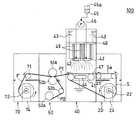
図3は、本発明の一実施形態に係る多孔質芯材(またはナノファイバシート)の製造方法を実施するための、製造システムの構成を概略的に示す図である。
図3の製造システム100は、ナノファイバシートを製造するための製造ラインを構成している。製造システム100では、基材シートSが製造ラインの上流から下流に搬送される。搬送途中の基材シートSには、多孔質シートP1の形成が随時行われる。FIG. 3 is a diagram schematically showing a configuration of a manufacturing system for carrying out a method for manufacturing a porous core material (or nanofiber sheet) according to an embodiment of the present invention.
The
製造システム100の最上流には、ロール状に捲回された基材シートSを内部に収容した基材シート供給装置20が設けられている。基材シート供給装置20は、ロール状の基材シートSを捲き出して、自身の下流側に隣接する別の装置に基材シートSを供給する。具体的には、基材シート供給装置20は、モータ24により供給リール22を回転させて、供給リール22に捲回された基材シートSを第1搬送コンベア21に供給する。 The uppermost stream of the
捲き出された基材シートSは、第1搬送コンベア21により、多孔質シート形成装置40に移送される。多孔質シート形成装置40は、電界紡糸機構を具備する。より具体的には、電界紡糸機構は、装置内の上方に設置された原料液を放出するための放出体42と、放出された原料液を帯電させる帯電手段と、放出体42と対向するように基材シートSを上流側から下流側に搬送する第3搬送コンベア41と、を備えている。第2搬送コンベア41は、基材シートSとともにナノファイバを収集するコレクタ部として機能する。 The rolled-out base sheet S is transferred to the porous
帯電手段は、放出体42に電圧を印加する電圧印加装置43と、第2搬送コンベア41と平行に設置された対電極44とで構成されている。対電極44は接地されている。これにより、放出体42と対電極44との間には、電圧印加装置43により印加される電圧に応じた電位差(例えば20〜200kV)を設けることができる。なお、帯電手段の構成は、特に限定されず、例えば、対電極44は必ずしも接地しなくてもよい。また、対電極44を設ける代わりに、第2搬送コンベア41のベルト部分を導体から構成するなどしてもよい。 The charging means includes a
放出体42は、導体で構成されており、長尺の形状を有し、その内部は中空になっている。中空部は原料液45を収容する収容部となる。放出体42の基材シートSと対向する側には、複数の放出口が、一定の間隔で、規則的な配列で設けられている。原料液45は、放出体42の中空部と連通するポンプ46の圧力により、原料液タンク45aから放出体42の中空に供給される。そして、原料液45は、ポンプ46の圧力により、複数の放出口から基材シートSの主面Saに向かって放出される。放出された原料液は、帯電した状態で放出体42と第3搬送コンベア41との間の空間を移動中に静電爆発を起し、ナノファイバを生成する。生成したナノファイバは、静電誘引力によって基材シートSの主面Saに誘引され、そこで堆積する。これにより、ナノファイバからなる多孔質層(不織布)が形成される。 The
第2搬送コンベア41の最も上流側には、基材シートSの主面Saと接触するスキージ47を設けてもよい。スキージ47により、ナノファイバを堆積させる前の基材シートSの主面Saの凹凸や皺を除くことができる。これにより、基材シートSは、第2搬送コンベア41のベルト部分の表面に密着する。従って、ナノファイバは、基材シートSの主面Saに、部分的に集中することなく、均一に堆積する。よって、形成される多孔質層の表面は平坦な状態になり、多孔質層の厚さが均一になりやすい。 A
第2搬送コンベア41のベルト部分は、誘電体であってもよい。上記のように、ベルト部分が導体で構成されている場合には、放出体42の放出口に近いコレクタ部にナノファイバが、やや集中して堆積する傾向がある。ナノファイバをより均一にコレクタ部に分散させる観点からは、第2搬送コンベア41のベルト部分を誘電体により形成することがより望ましい。ベルト部分を誘電体により形成した場合には、ベルト部分の内周面(基材シートSと接触する面の反対側の面)に、対電極44を接触させてもよい。このような接触により、ベルト部分の内部で誘電分極が起こり、基材シートSとの接触面に一様な電荷が発生する。これにより、ナノファイバが基材シートSの主面Saの一部に集中して堆積する可能性が更に低減される。 The belt portion of the
図4は、多孔質シート形成装置40の構成を概略的に示す上面図である。
多孔質シート形成装置40では、放出体42が基材シートSの移動方向(図4中の白抜き矢印の方向)に対して斜めに交わるように設置されている。このように放出体42を斜めに設置することで、第2搬送コンベア41と放出体42との対向面積が大きくなるため、多孔質層の生産性を高めることが可能である。なお、放出体42と矢印との成す鋭角θは、特に限定されないが、30〜60°程度とすることが、生産性を十分に向上させる上で好ましい。放出体42は、多孔質シート形成装置40の上方に設置された基材シートSの移動方向と平行な第1支持体48から下方に延びる第2支持体49により、自身の長手方向が基材シートSの主面Saと平行になるように支持されている。FIG. 4 is a top view schematically showing the configuration of the porous
In the porous
放出体42の基材シートSの主面Saと対向する側には、原料液の放出口42aが複数箇所設けられている。放出口42aを規則的なパターンで放出体42に配列させることで、基材シートSの主面Saに堆積するナノファイバの量を、主面Saの広い領域に渡って均一化することができる。放出体42の放出口42aと、基材シートSとの距離は、ナノファイバシートの製造システムの規模にもよるが、例えば、100〜600mmであればよい。 On the side of the
図3では、多孔質シート形成装置40が1台だけ設けられており、かつ1台の多孔質シート形成装置40が有する放出体42の数は2つであるが、多孔質シート形成装置40の台数や、1台の多孔質シート形成装置40が具備する放出体42の数は、特に限定されない。例えば、図5に示すように、2台の多孔質シート形成装置40を連続するように設けた製造システム200を構成してもよい。すなわち、2台の多孔質シート形成装置40の組みを、1つの電界紡糸機構として機能させてもよい。この場合、電界紡糸機構は、ラインの上流側に配置された第1電界紡糸ユニット40Aと、ラインの下流側に配置された第2電界紡糸ユニット40Bとを有すると考えることができる。 In FIG. 3, only one porous
なお、上記製造システムは、各装置が分離可能なように構成されている。そのため、各装置の台数を変更することは容易である。同様に、追加的機能を有する図示しない装置を、いずれかの隣接装置間に介在するように配置することもできる。 In addition, the said manufacturing system is comprised so that each apparatus can be isolate | separated. Therefore, it is easy to change the number of devices. Similarly, a device (not shown) having an additional function may be arranged so as to be interposed between any adjacent devices.
電界紡糸機構が、ラインの上流側に配置された第1電界紡糸ユニットと、ラインの下流側に配置された第2電界紡糸ユニットとを有する場合、各電界紡糸ユニットにより、同じナノファイバを生成させてもよく、異なるナノファイバを生成させてもよい。同じナノファイバを生成させる場合には、例えば、多孔質シートの厚さを大きくしたり、製造ラインを移動する基材シートSのスピードを速めて、製造タクトを向上させたりすることができる。また、異なるナノファイバを生成させる場合には、例えば、繊維径の異なるナノファイバを生成させることにより、複数層の異なる繊維層からなる多孔質シートを形成することができる。 When the electrospinning mechanism has a first electrospinning unit disposed on the upstream side of the line and a second electrospinning unit disposed on the downstream side of the line, each electrospinning unit generates the same nanofiber. Different nanofibers may be generated. When producing the same nanofiber, for example, the thickness of the porous sheet can be increased, or the speed of the base sheet S moving on the production line can be increased to improve the production tact. Moreover, when producing | generating different nanofibers, the porous sheet which consists of a several different fiber layer can be formed by producing | generating nanofibers from which a fiber diameter differs, for example.
ここで、上流側に配置される第1電界紡糸ユニットにより生成されるナノファイバの繊維径を、第2電界紡糸ユニットにより生成されるナノファイバの繊維径よりも意図的に大きくすれば、多孔質シートの基材シートS側を繊維径の大きいナノファイバにより構成することができ、基材シートSとは反対側を、繊維径のより小さいナノファイバにより構成することもできる。 Here, if the fiber diameter of the nanofiber generated by the first electrospinning unit disposed on the upstream side is intentionally larger than the fiber diameter of the nanofiber generated by the second electrospinning unit, the porous structure The base material sheet S side of the sheet can be composed of nanofibers having a large fiber diameter, and the side opposite to the base material sheet S can be composed of nanofibers having a small fiber diameter.
このような構造の多孔質シートの基材シートS側の表面同士を接合してナノファイバシートを形成すると、ナノファイバシートの厚さ方向の中心部におけるナノファイバの最大繊維径の平均Dcをより大きくすることができるとともに、第1および第2表面近傍におけるナノファイバの最大繊維径の平均Ds1およびDs2をより小さくすることができる。 When the nanofiber sheet is formed by joining the base sheet S side surfaces of the porous sheet having such a structure, the average Dc of the maximum fiber diameters of the nanofibers at the center portion in the thickness direction of the nanofiber sheet is further increased. The average Ds1 and Ds2 of the maximum fiber diameters of the nanofibers in the vicinity of the first and second surfaces can be further reduced.
なお、複数層の異なる繊維層からなる多孔質シートを形成する場合、異なる繊維層の数は、特に限定されないが、2〜5層が好ましく、2〜3層がより一般的である。 In addition, when forming the porous sheet which consists of a multiple layer different fiber layer, the number of different fiber layers is although it does not specifically limit, 2-5 layers are preferable and 2-3 layers are more common.
多孔質シート形成装置40において、基材シートSの表面に多孔質シートP1が形成されると、多孔質シートP1は、図中の矢印の方向に向かって次工程に搬送され、基材シートSは、多孔質シートP1から剥離されて、基材シートSの供給リール22に回収される。 When the porous sheet P1 is formed on the surface of the base sheet S in the porous
図3において、基材シートSと第2搬送コンベア41とが離間(剥離)する箇所には、基材シートSと第2搬送コンベア41のロールとが剥離するときに起こり得るスパークの発生を抑制するために、基材シートSを除電する除電装置を設けてもよい。また、多孔質シート形成装置40と、これに隣接する各装置との間の窓部近傍には、ナノファイバ形成空間で生成したナノファイバが外部に放出されないように、ナノファイバを吸引する吸引ダクトを設けてもよい。 In FIG. 3, the occurrence of a spark that may occur when the base sheet S and the roll of the
多孔質シート形成装置40から搬出された多孔質シート(第1多孔質シート)P1は、より下流側に配置されている多孔質シート接合装置50に移送される。このとき、多孔質シートP1は、基材シートS1と接触していない側の表面が、一対の圧着ローラ51a,51bのうち、圧着ローラ51aの周面に接触するように移送される。そして、同時に、多孔質シート接合装置50は、搬送されている多孔質シートP1の表面を覆うように第2多孔質シートP2を、図中の矢印の方向に、一対の圧着ローラ51a、51bの間に供給する。このとき、第1多孔質シートP1と第2多孔質シートP2とは、それぞれの基材シートに接触していた表面同士を対向させた状態となるように供給される。第1多孔質シートP1は、表面が乾いて基材シートS側が少し湿った状態であるのが好ましい。 The porous sheet (first porous sheet) P1 carried out from the porous
多孔質シート接合装置50は、供給リール52aに、基材シートに接触していた表面を外側にしてロール状に捲回された、第2多孔質シートP2を収容している。第2多孔質シートP2は、第1多孔質シートP1の移動方向と垂直に交わる回転軸を有し、かつ第1多孔質シートP1と平行な周面を有する搬送ローラ52bによって捲き出される。捲き出された第2多孔質シートP2は、一対の接合ローラ51a、51bの間に、第1多孔質シートP1と積層されるように供給される。そして、第1多孔質シートP1および第2多孔質シートP2が、積層した状態で、一対の接合ローラ51aおよび51b間のギャップを通過することにより、第1多孔質シートP1および第2多孔質シートP2が圧着されて一体化され、ナノファイバシートが完成する。 The porous
多孔質シートP1およびP2が圧着されるとき、第1多孔質シートP1の表面近傍が、溶媒を含んだ状態である場合、溶媒の作用により、第1多孔質シートP1の表面の繊維と、第2多孔質シートP2の表面の繊維とが溶着する。第2多孔質シートP2の表面近傍も、溶媒を含んだ状態であってもよい。接合ローラ51a,51bによる圧着は、加熱しながら行うことができる。 When the porous sheets P1 and P2 are pressure-bonded, when the vicinity of the surface of the first porous sheet P1 contains a solvent, the fibers on the surface of the first porous sheet P1 Two fibers on the surface of the porous sheet P2 are welded. The vicinity of the surface of the second porous sheet P2 may also contain a solvent. The pressure bonding by the joining
完成したナノファイバシートFは、搬送ローラ71を介して、回収装置70に回収される。回収装置70は、搬送されてくるナノファイバシートFを捲き取る回収リール72を内蔵している。回収リール72はモータ74により回転駆動される。 The completed nanofiber sheet F is collected by the
このようにして得られるナノファイバシートFは、回収装置70に一旦回収した後、高分子電解質の含浸工程に供してもよい。また、多孔質シート接合装置50と、回収装置70との間に、高分子電解質の含浸装置(図示せず)を設置し、多孔質シート接合装置50から搬送されたナノファイバシートFに、高分子電解質を含浸させて高分子電解質膜を形成し、回収装置70に搬送し、回収してもよい。 The nanofiber sheet F thus obtained may be once collected in the
図3に示すような製造システムでは、基材シート供給装置20と、ナノファイバシートを回収する回収装置70とを回転させるモータ74を、製造ラインを通過する基材シートSの搬送速度、多孔質シートの搬送速度が一定になるような回転速度に制御される。これにより、基材シートS、多孔質シートは、所定のテンションを維持しつつ搬送される。このような制御は、製造システム100に備えられた制御装置(図示せず)によって行われる。制御装置は、製造システム100を構成する各装置を統括的に制御し、管理できるように構成されている。 In the manufacturing system as shown in FIG. 3, the
多孔質シート接合装置50とナノファイバシート回収装置70との間には、予備回収部を配置してもよい。予備回収部は、完成されたナノファイバシートFの回収装置70による回収が容易となるように設けられる。具体的には、予備回収部では、多孔質シート接合装置50から移送されてくる完成したナノファイバシートFを、一定の長さまでは捲き取らずに弛んだ状態で回収する。その間、回収装置70の回収リール72は回転させずに停止させておく。そして、予備回収部により回収された弛んだ状態のナノファイバシートFの長さが一定の長さになる度に、回収装置70の回収リール72を所定時間だけ回転させて、回収リール72によりナノファイバシートFを捲き取る。このような予備回収部を設けることで、基材シート供給装置20とナノファイバシート回収装置70が具備するモータ24、74の回転速度を厳密に連動させて制御する必要がなくなり、製造システム100の制御装置を簡略化することができる。 A preliminary collection unit may be disposed between the porous
なお、上記のナノファイバシートの製造システムは、本発明の高分子電解質膜を構成するナノファイバシート(または多孔質芯材)の製造方法を実施するために用いることができる製造システムの一例に過ぎない。ナノファイバシートの製造方法は、ナノファイバ形成空間において、ナノファイバを生成させて、基材シートの主面に堆積させ、ナノファイバのマトリックス構造を有する多孔質シートを形成する工程と、一対の多孔質シートの基材シートと接触していた表面同士を対向させて接合し、ナノファイバシートを形成する工程とを有する限り、特に限定されない。 The above-described nanofiber sheet manufacturing system is merely an example of a manufacturing system that can be used to carry out the manufacturing method of the nanofiber sheet (or porous core material) constituting the polymer electrolyte membrane of the present invention. Absent. In the nanofiber sheet manufacturing method, a nanofiber is generated in a nanofiber formation space and deposited on a main surface of a base sheet to form a porous sheet having a nanofiber matrix structure; As long as it has the process of making the surface which contacted the base material sheet of the quality sheet face each other, joining, and forming a nanofiber sheet, it is not specifically limited.
基材シートをナノファイバ形成空間に供給する工程は、基材シート供給装置によりロール状の基材シートSを捲き出して、製造ラインの最上流に基材シートSを供給する工程に限定されない。例えば、基材シートSを製造する装置と一体化された製造ラインを用いることもできる。その場合、製造された直後の基材シートSを、そのまま多孔質シート形成装置に供給してもよい。 The step of supplying the base sheet to the nanofiber formation space is not limited to the step of rolling out the roll-shaped base sheet S by the base sheet supply device and supplying the base sheet S to the uppermost stream of the production line. For example, a production line integrated with an apparatus for producing the base sheet S can also be used. In that case, you may supply the base material sheet S immediately after manufacture to a porous sheet forming apparatus as it is.
また、多孔質シートを形成する工程についても、所定のナノファイバ形成空間において、原料液から静電気力によりナノファイバを生成させ、生成したナノファイバを基材シートSの主面に堆積させる工程であれば、どのような電界紡糸機構を用いてもよい。例えば、放出体の形状は、特に限定されない。放出体の長手方向に垂直な断面の形状は、上方から下方に向かって次第に小さくなる形状(V型ノズル)であってもよい。また、放出体を回転体により構成してもよい。 Also, the step of forming the porous sheet may be a step of generating nanofibers from the raw material liquid by electrostatic force in a predetermined nanofiber formation space and depositing the generated nanofibers on the main surface of the base sheet S. Any electrospinning mechanism may be used. For example, the shape of the emitter is not particularly limited. The shape of the cross section perpendicular to the longitudinal direction of the emitter may be a shape (V-type nozzle) that gradually decreases from the top to the bottom. Moreover, you may comprise a discharge body with a rotary body.
具体的には、放出体を、自転車用タイヤのチューブのような中空の環状体に形成し、当該中空に原料液を収容してもよい。そして、中空環状体の外周面に沿って複数の放出口を設け、中心を軸にして環状体を回転させれば、遠心力により放出口から原料液を放出させることができる。その場合、原料液の空間中での移動方向を、送風などにより制御すれば、所定のコレクタ部にナノファイバを堆積させることができる。 Specifically, the emitter may be formed into a hollow annular body such as a tube of a bicycle tire, and the raw material liquid may be accommodated in the hollow. If a plurality of discharge ports are provided along the outer peripheral surface of the hollow annular body and the annular body is rotated around the center, the raw material liquid can be discharged from the discharge port by centrifugal force. In that case, if the moving direction of the raw material liquid in the space is controlled by air blowing or the like, nanofibers can be deposited on a predetermined collector portion.
さらに、第1および第2多孔質シートを接合させる工程についても、どのような手法で行ってもよい。
なお、上記のナノファイバシートの製造方法は、特に、高分子電解質膜を構成する多孔質芯材の製造に適しているが、他の様々な用途に使用されるナノファイバシートの製造にも利用できる。Furthermore, the step of joining the first and second porous sheets may be performed by any method.
The above-described method for producing a nanofiber sheet is particularly suitable for producing a porous core material constituting a polymer electrolyte membrane, but is also used for producing a nanofiber sheet used in various other applications. it can.
また、上述の実施形態では、基材シートSが長尺状である場合について説明したが、本発明は、例えば矩形状の基材シートSを用いる場合にも適用可能である。この場合、基材シート供給装置は、例えば、矩形の基材シートを、順次、第1搬送コンベアに載置する装置であればよい。このような基材シート供給装置には、矩形の基材シートSを複数収容するトレイフィーダを併設させれば、効率よく、基材シートSを供給することができる。 Moreover, although the above-mentioned embodiment demonstrated the case where the base material sheet S was elongate, this invention is applicable also when, for example, the rectangular base material sheet S is used. In this case, the base material sheet supply apparatus may be an apparatus that sequentially places rectangular base material sheets on the first transport conveyor, for example. If such a base sheet supply apparatus is provided with a tray feeder that accommodates a plurality of rectangular base sheet S, the base sheet S can be supplied efficiently.
また、ナノファイバシートは、例えば、第1および第2ラインの上流から下流にそれぞれ長尺の第1および第2基材シートを搬送し、上流側で、第1および第2基材シートの主面にそれぞれ第1および第2多孔質シートを形成し、下流側で、第1および第2多孔質シートを対向させて接合する製造方法により、製造することもできる。 Further, the nanofiber sheet, for example, conveys the long first and second substrate sheets from the upstream to the downstream of the first and second lines, respectively, and on the upstream side, the main fibers of the first and second substrate sheets It can also be manufactured by a manufacturing method in which the first and second porous sheets are formed on the surfaces and the first and second porous sheets are opposed to each other on the downstream side.
このようなナノファイバシートの製造方法は、例えば、
(i)第1および第2基材シートを、第1および第2ラインの上流側のナノファイバ形成空間に搬送する工程と、
(ii)ナノファイバ形成空間において、溶媒および溶媒に溶解した樹脂原料を含む原料液から静電気力によりナノファイバを生成させるとともに、生成したナノファイバを搬送される第1および第2基材シートの主面にそれぞれ堆積させて、ナノファイバのマトリックス構造を有する第1および第2多孔質シートを形成する工程と、
(iii)第1および第2ラインの下流側で、搬送される第1および第2多孔質シートから第1および第2基材シートを除去する工程と、
(iv)第1および第2ラインの更に下流側で、搬送される第1および第2多孔質シートの第1および第2基材シートの主面と接触していた表面同士を対向させて接合してナノファイバシートを形成する工程と、を有する。
このようにして得られたナノファイバシートを、高分子電解質を含浸させることにより、高分子電解質膜を製造することができる。高分子電解質の含浸は、上記ラインのさらに下流側で行っても良い。A method for producing such a nanofiber sheet is, for example,
(I) conveying the first and second substrate sheets to the nanofiber formation space upstream of the first and second lines;
(Ii) In the nanofiber formation space, nanofibers are generated by electrostatic force from a raw material solution containing a solvent and a resin raw material dissolved in the solvent, and the main of the first and second base sheet transported the generated nanofibers Forming first and second porous sheets having a matrix structure of nanofibers, each deposited on a surface;
(Iii) removing the first and second substrate sheets from the conveyed first and second porous sheets on the downstream side of the first and second lines;
(Iv) On the further downstream side of the first and second lines, the surfaces of the first and second porous sheets to be conveyed that are in contact with the main surfaces of the first and second substrate sheets are opposed to each other. And forming a nanofiber sheet.
A polymer electrolyte membrane can be produced by impregnating the nanofiber sheet thus obtained with a polymer electrolyte. The impregnation of the polymer electrolyte may be performed further downstream of the above line.
工程(iv)では、第1および第2多孔質シートの少なくとも第1および第2基材シートの主面と接触していた表面近傍が溶媒を含んだ状態で、第1および第2多孔質シートを接合し、第1多孔質シートのナノファイバと、第2多孔質シートのナノファイバとを溶着させてもよい。 In the step (iv), the first and second porous sheets are in a state in which at least the surfaces of the first and second porous sheets in contact with the main surfaces of the first and second base sheets contain a solvent. The nanofibers of the first porous sheet and the nanofibers of the second porous sheet may be welded together.
図6は、本発明の一実施形態に係る高分子電解質膜を構成する多孔質芯材(またはナノファイバシート)の製造方法を実施するための、製造システムの構成を概略的に示す図である。
図6の製造システム300は、第1ラインの最上流に、基材シート供給装置20Aが設けられているとともに、第2ラインの最上流に、基材シート供給装置20Bが設けられている。製造システム300は、図3の製造システム100において、第2多孔質シートP2を、多孔質シート接合装置50の供給リール52aから供給せずに、第1多孔質シートと並行して同様に製造しながら、連続的に、一対の接合ローラ51a,51b間に供給する以外は、図3の製造システム100と同様である。FIG. 6 is a diagram schematically showing a configuration of a manufacturing system for carrying out a method for manufacturing a porous core material (or nanofiber sheet) constituting a polymer electrolyte membrane according to an embodiment of the present invention. .
In the
ただし、図6では、便宜上、多孔質シート接合装置の符号を50Aとし、基材シート供給装置およびその構成要素を、それぞれ、基材シート供給装置20A、供給リール22a、第1搬送コンベア21aで表す。基材シート供給装置20Aは、モータ24aにより供給リール22aを回転させて、供給リール22aに捲回された第1基材シートS1を、第1搬送コンベア21aに供給する。捲き出された第1基材シートS1は、主面S1aが多孔質シート形成装置40内の放出体42と対向するように、第1搬送コンベア21aにより、多孔質シート形成装置40に移送され、多孔質シート形成装置40で、第1多孔質シートP1が形成される。 However, in FIG. 6, for the sake of convenience, the reference numeral of the porous sheet joining apparatus is 50A, and the base sheet supply apparatus and its constituent elements are represented by the base
第2多孔質シートP2は、第1多孔質シートP1と同様にして形成される。具体的には、次のようにして形成される。まず、基材シート供給装置20Bは、供給リール22bに捲回された第2基材シートS2を、モータ24bによる供給リール22bの回転により、第1搬送コンベア21bに供給する。第1搬送コンベア21bは、捲き出された第2基材シートS2を、第2ラインの基材シート供給装置20Bの下流側に位置する多孔質シート形成装置80に移送し、多孔質シート形成装置80では、多孔質シート形成装置40と同様の機構により、多孔質シート(第2多孔質シートP2)が形成される。 The second porous sheet P2 is formed in the same manner as the first porous sheet P1. Specifically, it is formed as follows. First, the base
第1および第2ラインの下流側にそれぞれ位置する多孔質シート形成装置40および80では、それぞれ第1および第2多孔質シートP1およびP2が形成された後、搬送コンベア41および81により、それぞれ次工程に供給される。そして、第1および第2基材シートS1およびS2は、それぞれ、多孔質シートP1およびP2から除去されて、供給リール22aおよび22bに回収される。 In the porous
第1および第2ラインのさらに下流側には、多孔質シート接合装置50Aが配設されている。第1ラインの多孔質シート形成装置40から搬送される第1多孔質シートP1と、第2ラインの多孔質シート形成装置80から搬送される第2多孔質シートP2とは、第1および第2基材シートS1およびS2のそれぞれの主面S1aおよびS2aと接触していた表面同士が対向するように、一対の接合ローラ51aおよび51b間に供給される。 A porous
多孔質シート接合装置50Aでは、図3における多孔質シート接合装置50における接合の機構と同様して、一対の接合ローラ51aおよび51b間のギャップを通過することにより、第1および第2多孔質シートP1およびP2が圧着されて一体化され、ナノファイバシートが完成する。 In the porous
完成したナノファイバシートFは、図3の場合と同様にして、回収装置70に回収される。この場合にも、図3の場合と同様に、ナノファイバシートFは、回収装置70に一旦回収した後、高分子電解質の含浸工程に供してもよい。また、多孔質シート接合装置50Aと、回収装置70との間に、高分子電解質の含浸装置(図示せず)を設置し、ナノファイバシートFに、高分子電解質を含浸させて高分子電解質膜を形成し、回収装置70に搬送し、回収してもよい。 The completed nanofiber sheet F is recovered by the
図6に示すような製造システムでも、図3の場合に準じて、図示しない制御装置により、基材シートS1およびS2、多孔質シートP1およびP2などの搬送速度を一定に制御してもよい。また、多孔質シート接合装置50Aと、ナノファイバシート回収装置70との間に、上記と同様に、予備回収部を配置してもよい。 Also in the manufacturing system as shown in FIG. 6, according to the case of FIG. 3, the conveying speed of the base sheets S1 and S2, the porous sheets P1 and P2, etc. may be controlled to be constant by a control device (not shown). In addition, a preliminary recovery unit may be disposed between the porous
本発明では、電界紡糸法により形成されるナノファイバのマトリックス構造(ナノファイバ不織布構造)を有しながらも、両表面近傍の最大繊維径の平均が、厚さ方向の中心部における最大繊維径の平均よりも小さいナノファイバシート(不織布)が得られる。このようなナノファイバシートは、表面の性質に優れるとともに、両表面の性質に大きな違いがないため、高分子電解質膜を構成する多孔質芯材に適している。 In the present invention, while having a nanofiber matrix structure (nanofiber nonwoven fabric structure) formed by electrospinning, the average of the maximum fiber diameters in the vicinity of both surfaces is the maximum fiber diameter at the center in the thickness direction. A nanofiber sheet (nonwoven fabric) smaller than the average is obtained. Such a nanofiber sheet is suitable for a porous core material constituting a polymer electrolyte membrane because it has excellent surface properties and there is no significant difference in properties between both surfaces.
1:ナノファイバシート、1a:第1表面、1b:第1表面近傍、2a:第2表面、2b:第2表面近傍、P1:第1多孔質シート、P2:第2多孔質シートP2、3a:接合面、3:ナノファイバシートの厚さ方向の中心部近傍 1: nanofiber sheet, 1a: first surface, 1b: near first surface, 2a: second surface, 2b: near second surface, P1: first porous sheet, P2: second porous sheet P2, 3a : Bonding surface, 3: Near the center of the nanofiber sheet in the thickness direction
11:燃料電池、110:電解質膜、111:アノード、112:カソード、113 膜電極接合体(MEA)、114:アノード側セパレータ、115:カソード側セパレータ、116:アノード触媒層、117:アノード拡散層、118:カソード触媒層、119:カソード拡散層、120、121:流路、122:アノード側ガスケット、123:カソード側ガスケット、124、125:集電板、126、127:シート状のヒータ、128、129:絶縁板、130、131:端板 11: fuel cell, 110: electrolyte membrane, 111: anode, 112: cathode, 113 membrane electrode assembly (MEA), 114: anode side separator, 115: cathode side separator, 116: anode catalyst layer, 117: anode diffusion layer 118: cathode catalyst layer, 119: cathode diffusion layer, 120, 121: flow path, 122: anode side gasket, 123: cathode side gasket, 124, 125: current collector plate, 126, 127: sheet heater, 128 129: Insulating plate, 130, 131: End plate
100,200,300:ナノファイバシート(多孔質芯材)の製造システム
20,20A,20B:基材シート供給装置、21,21a,21b:第1搬送コンベア、22,22a,22b:供給リール、100, 200, 300: Nanofiber sheet (porous core material)
40,80:多孔質シート形成装置、40A:第1電界紡糸ユニット、40B:第2電解紡糸ユニット、41,81:第2搬送コンベア、42,82:放出体、42a:放出口、43,83:電圧印加装置、44,84:対電極、45,85:原料液、45a,85a:原料液タンク、46,86:ポンプ、47,87:スキージ、48,88:第1支持体、49,89:第2支持体、 40, 80: porous sheet forming apparatus, 40A: first electrospinning unit, 40B: second electrospinning unit, 41, 81: second transport conveyor, 42, 82: discharge body, 42a: discharge port, 43, 83 : Voltage application device, 44, 84: Counter electrode, 45, 85: Raw material liquid, 45a, 85a: Raw material liquid tank, 46, 86: Pump, 47, 87: Squeegee, 48, 88: First support, 49, 89: Second support,
50,50A:多孔質シート接合装置、51a,51b:接合ローラ、52a:供給リール、52b:搬送ローラ、
70:回収装置、71:搬送ローラ、72:回収リール、50, 50A: Porous sheet joining apparatus, 51a, 51b: joining roller, 52a: supply reel, 52b: transport roller,
70: collection device, 71: transport roller, 72: collection reel,
S:基材シート、S1:第1基材シート、S2:第2基材シート、Sa:基材シートの主面、S1a:第1基材シートの主面、S2a:第1基材シートの主面、F:ナノファイバシート(高分子電解質膜の多孔質芯材) S: base material sheet, S1: first base material sheet, S2: second base material sheet, Sa: main surface of base material sheet, S1a: main surface of first base material sheet, S2a: first base material sheet Main surface, F: Nanofiber sheet (Porous core material of polymer electrolyte membrane)
Claims (12)
Translated fromJapanese前記多孔質芯材に含浸させた高分子電解質と、を具備し、
前記多孔質芯材は、堆積されたナノファイバで形成された前記ナノファイバのマトリックス構造を有する一対の多孔質シートの接合物であり、前記一対の多孔質シートの、堆積により前記ナノファイバが押し潰された側の表面同士が接合されており、前記一対の多孔質シートの前記ナノファイバが押し潰された側の裏面がそれぞれ前記第1表面および前記第2表面であり、
前記多孔質芯材の面方向における前記ナノファイバの最大繊維径の平均を、前記第1表面近傍および前記第2表面近傍と、前記多孔質芯材の厚さ方向の中心部とで比較したとき、前記第1表面近傍における前記ナノファイバの最大繊維径の平均Ds1および前記第2表面近傍における前記ナノファイバの最大繊維径の平均Ds2が、前記多孔質芯材の厚さ方向の中心部における前記ナノファイバの最大繊維径の平均Dcより小さく、
前記第1表面近傍は、前記第1表面から前記多孔質芯材の全体の厚さの10%の厚さを有する領域であり、
前記第2表面近傍は、前記第2表面から前記多孔質芯材の全体の厚さの10%の厚さを有する領域である、高分子電解質膜。A sheet-shaped porous core material having a first surface and a second surface opposite tothe first surface;
A polymer electrolyte impregnated in the porous core material,
The porous core material is a joined product of a pair of porous sheets having a matrix structure of the nanofibers formed by deposited nanofibers, and the nanofibers are pushed by the deposition of the pair of porous sheets. The crushed surfaces are joined to each other, and the back surfaces of the pair of porous sheets on which the nanofibers are crushed are the first surface and the second surface, respectively.
When the average of the maximum fiber diameters of the nanofibers in the plane direction of the porous core material is compared between the vicinity of the first surface and the vicinity of the second surface, and the central portion in the thickness direction of the porous core material The average Ds1 of the maximum fiber diameters of the nanofibers in the vicinity of the first surface and the average Ds2 of the maximum fiber diameters of the nanofibers in the vicinity of the second surface are the center part in the thickness direction of the porous core material. Smaller than the average Dc of the maximum fiber diameter of the nanofibers,
The vicinity of the first surface is a region having a thickness of 10% of the total thickness of the porous core material from the first surface,
The vicinity of the second surface is a polymer electrolyte membrane that is a region having a thickness of 10% of the entire thickness of the porous core material from the second surface.
前記アノードに接触するとともに、前記アノードに燃料を供給する燃料流路を有するアノード側セパレータと、
前記カソードに接触するとともに、前記カソードに酸化剤を供給するカソード側セパレータと、を具備する高分子電解質型燃料電池。A membrane electrode assembly according to claim8 ,
An anode separator having a fuel flow path for contacting the anode and supplying fuel to the anode;
A polymer electrolyte fuel cell comprising: a cathode separator that contacts the cathode and supplies an oxidant to the cathode.
前記カソードが、前記高分子電解質膜に接触するカソード触媒層と、前記カソード触媒層に積層されたカソード拡散層と、を含み、
前記アノード拡散層は、前記アノード触媒層に接触するアノード多孔質撥水層と、前記アノード多孔質撥水層に積層され、前記アノード側セパレータと接触するアノード多孔質基材層と、を含み、
前記カソード拡散層は、前記カソード触媒層に接触するカソード多孔質撥水層と、前記カソード多孔質撥水層に積層され、前記カソード側セパレータと接触するカソード多孔質基材層と、を含む、請求項9に記載の高分子電解質型燃料電池。The anode includes an anode catalyst layer in contact with the polymer electrolyte membrane; and an anode diffusion layer laminated on the anode catalyst layer;
The cathode includes a cathode catalyst layer in contact with the polymer electrolyte membrane; and a cathode diffusion layer laminated on the cathode catalyst layer;
The anode diffusion layer includes an anode porous water-repellent layer in contact with the anode catalyst layer, and an anode porous substrate layer laminated on the anode porous water-repellent layer and in contact with the anode-side separator,
The cathode diffusion layer includes a cathode porous water-repellent layer in contact with the cathode catalyst layer, and a cathode porous substrate layer laminated on the cathode porous water-repellent layer and in contact with the cathode-side separator. The polymer electrolyte fuel cell according to claim9 .
(ii)前記多孔質芯材に高分子電解質を含浸させる工程と、を有し、
前記ナノファイバの前記多孔質芯材の面方向における最大繊維径の平均を、前記第1表面近傍および前記第2表面近傍と、前記多孔質芯材の厚さ方向の中心部とで比較したとき、前記第1表面近傍における前記ナノファイバの最大繊維径の平均Ds1および前記第2表面近傍における前記ナノファイバの最大繊維径の平均Ds2が、前記多孔質芯材の厚さ方向の中心部における前記ナノファイバの最大繊維径の平均Dcより小さく、
前記第1表面近傍は、前記第1表面から前記多孔質芯材の全体の厚さの10%の厚さを有する領域であり、
前記第2表面近傍は、前記第2表面から前記多孔質芯材の全体の厚さの10%の厚さを有する領域であり、
前記工程(i)が、
(a)基材シートをナノファイバ形成空間に供給する工程と、
(b)前記ナノファイバ形成空間において、溶媒および前記溶媒に溶解した樹脂原料を含む原料液から静電気力によりナノファイバを生成させるとともに、前記生成したナノファイバを前記基材シートの主面に堆積させて、ナノファイバのマトリックス構造を有する多孔質シートを形成する工程と、
(c)一対の前記多孔質シートを、前記基材シートの主面と接触していた表面同士を対向させて接合し、前記一対の多孔質シートの前記基材シートの主面と接触していなかった表面をそれぞれ第1表面およびその反対側の第2表面とする多孔質芯材を形成する工程と、を有する、高分子電解質膜の製造方法。(I) preparing a sheet-shaped porous core material having a matrix structure of nanofibers formed by electrospinning and having a first surface and a second surface opposite to the first surface;
(Ii) impregnating the porous core material with a polymer electrolyte, and
When the average of the maximum fiber diameters in the surface direction of the porous core material of the nanofiber is compared between the vicinity of the first surface and the vicinity of the second surface, and the central portion in the thickness direction of the porous core material The average Ds1 of the maximum fiber diameters of the nanofibers in the vicinity of the first surface and the average Ds2 of the maximum fiber diameters of the nanofibers in the vicinity of the second surface are the center part in the thickness direction of the porous core material. Smaller than the average Dc of the maximum fiber diameter of the nanofibers,
The vicinity of the first surface is a region having a thickness of 10% of the total thickness of the porous core material from the first surface,
The second near the surface,Ri regions der with 10% of the thickness of the total thickness of the porous core material from said secondsurface,
The step (i)
(A) supplying a base sheet to the nanofiber formation space;
(B) In the nanofiber formation space, nanofibers are generated by electrostatic force from a raw material liquid containing a solvent and a resin raw material dissolved in the solvent, and the generated nanofibers are deposited on the main surface of the base sheet. Forming a porous sheet having a nanofiber matrix structure;
(C) A pair of the porous sheets are bonded so that the surfaces that have been in contact with the main surface of the base sheet are opposed to each other, and are in contact with the main surface of the base sheet of the pair of porous sheets. forming a porous core material for a never been surface and the first surface and opposite second surface thereof, respectively, thathave a method for producing a polymer electrolyte membrane.
(i)前記第1および第2基材シートを、前記第1および第2ラインの上流側のナノファイバ形成空間に搬送する工程と、
(ii)前記ナノファイバ形成空間において、溶媒および前記溶媒に溶解した樹脂原料を含む原料液から静電気力によりナノファイバを生成させるとともに、前記生成したナノファイバを搬送される前記第1および第2基材シートの主面にそれぞれ堆積させて、ナノファイバのマトリックス構造を有する第1および第2多孔質シートを形成する工程と、
(iii)前記第1および第2ラインの下流側で、搬送される前記第1および第2多孔質シートから前記第1および第2基材シートを除去する工程と、
(iv)前記第1および第2ラインの更に下流側で、搬送される前記第1および第2多孔質シートの前記第1および第2基材シートの主面と接触していた表面同士を対向させて接合して多孔質芯材を形成する工程と、を有し、
前記多孔質芯材は、第1表面およびその反対側の第2表面を有し、
前記第1表面近傍における前記ナノファイバの最大繊維径の平均Ds1および前記第2表面近傍における前記ナノファイバの最大繊維径の平均Ds2が、前記多孔質芯材の厚さ方向の中心部における前記ナノファイバの最大繊維径の平均Dcより小さく、
前記第1表面近傍は、前記第1表面から前記多孔質芯材の全体の厚さの10%の厚さを有する領域であり、
前記第2表面近傍は、前記第2表面から前記多孔質芯材の全体の厚さの10%の厚さを有する領域である、高分子電解質膜の製造方法。The first and second base sheets that are long are conveyed from the upstream side to the downstream side of the first and second lines, respectively, and on the upstream side, the first and second surfaces are respectively formed on the main surfaces of the first and second base sheet. A polymer that forms a porous sheet and, on the downstream side, obtains a porous core material by facing and joining the first and second porous sheets, and impregnates the porous core material with a polymer electrolyte. An electrolyte membrane manufacturing method comprising:
(I) transporting the first and second base sheets to a nanofiber formation space upstream of the first and second lines;
(Ii) In the nanofiber formation space, nanofibers are generated by electrostatic force from a raw material liquid containing a solvent and a resin raw material dissolved in the solvent, and the first and second groups are transported by the generated nanofibers. Forming first and second porous sheets having a matrix structure of nanofibers, each deposited on a main surface of a material sheet;
(Iii) removing the first and second base material sheets from the first and second porous sheets conveyed on the downstream side of the first and second lines;
(Iv) On the further downstream side of the first and second lines, the surfaces of the first and second porous sheets conveyed that are in contact with the main surfaces of the first and second substrate sheets are opposed to each other. And bonding to form a porous core material,
The porous core material has a first surface and a second surface opposite to the first surface;
The average Ds1 of the maximum fiber diameters of the nanofibers in the vicinity of the first surface and the average Ds2 of the maximum fiber diameters of the nanofibers in the vicinity of the second surface are the nano at the center in the thickness direction of the porous core material. Smaller than the average Dc of the maximum fiber diameter of the fiber,
The vicinity of the first surface is a region having a thickness of 10% of the total thickness of the porous core material from the first surface,
The method for producing a polymer electrolyte membrane, wherein the vicinity of the second surface is a region having a thickness of 10% of the total thickness of the porous core material from the second surface.
Priority Applications (1)
| Application Number | Priority Date | Filing Date | Title |
|---|---|---|---|
| JP2012123714AJP5919554B2 (en) | 2012-05-30 | 2012-05-30 | POLYMER ELECTROLYTE MEMBRANE, MEMBRANE ELECTRODE ASSEMBLY, POLYMER ELECTROLYTE FUEL CELL, AND METHOD FOR PRODUCING POLYMER ELECTROLYTE MEMBRANE |
Applications Claiming Priority (1)
| Application Number | Priority Date | Filing Date | Title |
|---|---|---|---|
| JP2012123714AJP5919554B2 (en) | 2012-05-30 | 2012-05-30 | POLYMER ELECTROLYTE MEMBRANE, MEMBRANE ELECTRODE ASSEMBLY, POLYMER ELECTROLYTE FUEL CELL, AND METHOD FOR PRODUCING POLYMER ELECTROLYTE MEMBRANE |
Publications (2)
| Publication Number | Publication Date |
|---|---|
| JP2013251078A JP2013251078A (en) | 2013-12-12 |
| JP5919554B2true JP5919554B2 (en) | 2016-05-18 |
Family
ID=49849582
Family Applications (1)
| Application Number | Title | Priority Date | Filing Date |
|---|---|---|---|
| JP2012123714AExpired - Fee RelatedJP5919554B2 (en) | 2012-05-30 | 2012-05-30 | POLYMER ELECTROLYTE MEMBRANE, MEMBRANE ELECTRODE ASSEMBLY, POLYMER ELECTROLYTE FUEL CELL, AND METHOD FOR PRODUCING POLYMER ELECTROLYTE MEMBRANE |
Country Status (1)
| Country | Link |
|---|---|
| JP (1) | JP5919554B2 (en) |
Cited By (1)
| Publication number | Priority date | Publication date | Assignee | Title |
|---|---|---|---|---|
| US11557783B2 (en) | 2019-09-05 | 2023-01-17 | Hyundai Motor Company | Polymer electrolyte membrane for fuel cells and method for manufacturing the same |
Families Citing this family (3)
| Publication number | Priority date | Publication date | Assignee | Title |
|---|---|---|---|---|
| JP6612715B2 (en)* | 2016-11-14 | 2019-11-27 | 株式会社東芝 | Electrospinning device |
| EP3609014B1 (en)* | 2017-03-28 | 2024-04-03 | Kabushiki Kaisha Toshiba | Electrode structure and secondary battery |
| JP2019194387A (en)* | 2019-07-01 | 2019-11-07 | 株式会社東芝 | Electrospinning device |
Family Cites Families (5)
| Publication number | Priority date | Publication date | Assignee | Title |
|---|---|---|---|---|
| JP5151063B2 (en)* | 2006-04-19 | 2013-02-27 | トヨタ自動車株式会社 | Porous material for electrolyte membrane for fuel cell, production method thereof, electrolyte membrane for polymer electrolyte fuel cell, membrane-electrode assembly (MEA), and fuel cell |
| JP4827781B2 (en)* | 2007-03-30 | 2011-11-30 | Nok株式会社 | Polymer electrolyte membrane |
| JP2009097120A (en)* | 2007-10-18 | 2009-05-07 | Toray Ind Inc | Laminated nonwoven fabric for cosmetic sheet product |
| JP5407429B2 (en)* | 2008-10-28 | 2014-02-05 | Jsr株式会社 | Proton conducting membrane and method for producing the same, membrane-electrode assembly, polymer electrolyte fuel cell |
| JP5432033B2 (en)* | 2010-03-31 | 2014-03-05 | 日本バイリーン株式会社 | Polymer electrolyte membrane |
- 2012
- 2012-05-30JPJP2012123714Apatent/JP5919554B2/ennot_activeExpired - Fee Related
Cited By (1)
| Publication number | Priority date | Publication date | Assignee | Title |
|---|---|---|---|---|
| US11557783B2 (en) | 2019-09-05 | 2023-01-17 | Hyundai Motor Company | Polymer electrolyte membrane for fuel cells and method for manufacturing the same |
Also Published As
| Publication number | Publication date |
|---|---|
| JP2013251078A (en) | 2013-12-12 |
Similar Documents
| Publication | Publication Date | Title |
|---|---|---|
| JP5830654B2 (en) | Method for producing polymer electrolyte membrane | |
| JP5355828B1 (en) | Battery, battery separator and battery separator manufacturing method | |
| US8617751B2 (en) | Water control sheet, gas diffusion sheet, membrane-electrode assembly and polymer electrolyte fuel cell | |
| CN104871354B (en) | Reinforced composite membrane for fuel cell and membrane electrode assembly comprising same | |
| US8968909B2 (en) | Fibrous separation membrane for secondary battery and manufacturing method thereof | |
| US20100314038A1 (en) | Process for producing membrane/electrode assembly for polymer electrolyte fuel cell | |
| KR101178644B1 (en) | Ion conductive hybrid membrane, membrane-electrode assembly and fuel cell | |
| US20180126408A1 (en) | Method for manufacturing carbon nanotube composite sheet | |
| JP5919554B2 (en) | POLYMER ELECTROLYTE MEMBRANE, MEMBRANE ELECTRODE ASSEMBLY, POLYMER ELECTROLYTE FUEL CELL, AND METHOD FOR PRODUCING POLYMER ELECTROLYTE MEMBRANE | |
| JP7145274B2 (en) | Carbon fiber sheet, gas diffusion electrode, membrane-electrode assembly, polymer electrolyte fuel cell, and method for producing carbon fiber sheet | |
| KR101646707B1 (en) | Ion Exchange Membrane, Method For Manufacturing The Same, Membrane Electrode Assembly and Fuel Cell | |
| JP2016169450A (en) | Electric conductive fiber sheet, gas diffusion electrode, membrane-electrode conjugate, solid polymer fuel cell and manufacturing method of electric conductive fiber sheet | |
| JP5909685B2 (en) | Nanofiber sheet, capacitor separator, capacitor, and method of manufacturing capacitor separator | |
| KR102000696B1 (en) | Coating machine for separator of secondary battery | |
| US10916783B2 (en) | Separator for fuel cell, method of fabricating the same, and fuel cell electrode assembly | |
| JP5853194B2 (en) | Membrane-catalyst layer assembly manufacturing method and manufacturing apparatus thereof | |
| JP7586072B2 (en) | METHOD AND APPARATUS FOR PRODUCING MEMBRANE-CATALYST ASSEMBLIES | |
| KR101936353B1 (en) | Ion Exchange Membrane, Membrane Electrode Assembly and Fuel Cell | |
| KR20170003278A (en) | Shrink-resistance laminate, method for manufacturing the shrink-resistance laminate and device for manufacturing the shrink-resistance | |
| JP2018018684A (en) | Membrane-conductive porous sheet assembly and polymer electrolyte fuel cell | |
| KR20170003276A (en) | Manufacturing methode of reinforced membrane, manufacturing apparatus of reinforced membrane and reinforced membrane | |
| JP2017195087A (en) | Membrane-electrode assembly and solid polymer fuel cell | |
| KR20220093516A (en) | Apparatus and Method for Manufacturing Membrane-Electrode Assembly | |
| JP2020098736A (en) | Manufacturing equipment for fuel cell electrodes | |
| JP2019220344A (en) | Method of manufacturing membrane electrode assembly and fuel cell |
Legal Events
| Date | Code | Title | Description |
|---|---|---|---|
| A621 | Written request for application examination | Free format text:JAPANESE INTERMEDIATE CODE: A621 Effective date:20140811 | |
| A711 | Notification of change in applicant | Free format text:JAPANESE INTERMEDIATE CODE: A711 Effective date:20141009 | |
| RD03 | Notification of appointment of power of attorney | Free format text:JAPANESE INTERMEDIATE CODE: A7423 Effective date:20141028 | |
| A977 | Report on retrieval | Free format text:JAPANESE INTERMEDIATE CODE: A971007 Effective date:20150325 | |
| A131 | Notification of reasons for refusal | Free format text:JAPANESE INTERMEDIATE CODE: A131 Effective date:20150326 | |
| A521 | Request for written amendment filed | Free format text:JAPANESE INTERMEDIATE CODE: A523 Effective date:20150512 | |
| A131 | Notification of reasons for refusal | Free format text:JAPANESE INTERMEDIATE CODE: A131 Effective date:20151006 | |
| A521 | Request for written amendment filed | Free format text:JAPANESE INTERMEDIATE CODE: A523 Effective date:20151203 | |
| TRDD | Decision of grant or rejection written | ||
| A01 | Written decision to grant a patent or to grant a registration (utility model) | Free format text:JAPANESE INTERMEDIATE CODE: A01 Effective date:20160209 | |
| A61 | First payment of annual fees (during grant procedure) | Free format text:JAPANESE INTERMEDIATE CODE: A61 Effective date:20160229 | |
| R151 | Written notification of patent or utility model registration | Ref document number:5919554 Country of ref document:JP Free format text:JAPANESE INTERMEDIATE CODE: R151 | |
| LAPS | Cancellation because of no payment of annual fees |