JP5918497B2 - Radio communication system, radio base station apparatus, machine communication terminal, and radio communication method - Google Patents
Radio communication system, radio base station apparatus, machine communication terminal, and radio communication methodDownload PDFInfo
- Publication number
- JP5918497B2 JP5918497B2JP2011224343AJP2011224343AJP5918497B2JP 5918497 B2JP5918497 B2JP 5918497B2JP 2011224343 AJP2011224343 AJP 2011224343AJP 2011224343 AJP2011224343 AJP 2011224343AJP 5918497 B2JP5918497 B2JP 5918497B2
- Authority
- JP
- Japan
- Prior art keywords
- base station
- station apparatus
- radio base
- machine communication
- communication terminal
- Prior art date
- Legal status (The legal status is an assumption and is not a legal conclusion. Google has not performed a legal analysis and makes no representation as to the accuracy of the status listed.)
- Active
Links
Images


Classifications
- H—ELECTRICITY
- H04—ELECTRIC COMMUNICATION TECHNIQUE
- H04W—WIRELESS COMMUNICATION NETWORKS
- H04W52/00—Power management, e.g. Transmission Power Control [TPC] or power classes
- H04W52/02—Power saving arrangements
- H04W52/0209—Power saving arrangements in terminal devices
- H04W52/0212—Power saving arrangements in terminal devices managed by the network, e.g. network or access point is leader and terminal is follower
- H04W52/0216—Power saving arrangements in terminal devices managed by the network, e.g. network or access point is leader and terminal is follower using a pre-established activity schedule, e.g. traffic indication frame
- H—ELECTRICITY
- H04—ELECTRIC COMMUNICATION TECHNIQUE
- H04W—WIRELESS COMMUNICATION NETWORKS
- H04W72/00—Local resource management
- H04W72/04—Wireless resource allocation
- H—ELECTRICITY
- H04—ELECTRIC COMMUNICATION TECHNIQUE
- H04L—TRANSMISSION OF DIGITAL INFORMATION, e.g. TELEGRAPHIC COMMUNICATION
- H04L1/00—Arrangements for detecting or preventing errors in the information received
- H04L1/12—Arrangements for detecting or preventing errors in the information received by using return channel
- H04L1/16—Arrangements for detecting or preventing errors in the information received by using return channel in which the return channel carries supervisory signals, e.g. repetition request signals
- H04L1/18—Automatic repetition systems, e.g. Van Duuren systems
- H04L1/1825—Adaptation of specific ARQ protocol parameters according to transmission conditions
- H—ELECTRICITY
- H04—ELECTRIC COMMUNICATION TECHNIQUE
- H04L—TRANSMISSION OF DIGITAL INFORMATION, e.g. TELEGRAPHIC COMMUNICATION
- H04L1/00—Arrangements for detecting or preventing errors in the information received
- H04L1/12—Arrangements for detecting or preventing errors in the information received by using return channel
- H04L1/16—Arrangements for detecting or preventing errors in the information received by using return channel in which the return channel carries supervisory signals, e.g. repetition request signals
- H04L1/18—Automatic repetition systems, e.g. Van Duuren systems
- H04L1/1829—Arrangements specially adapted for the receiver end
- H04L1/1835—Buffer management
- H—ELECTRICITY
- H04—ELECTRIC COMMUNICATION TECHNIQUE
- H04L—TRANSMISSION OF DIGITAL INFORMATION, e.g. TELEGRAPHIC COMMUNICATION
- H04L1/00—Arrangements for detecting or preventing errors in the information received
- H04L1/12—Arrangements for detecting or preventing errors in the information received by using return channel
- H04L1/16—Arrangements for detecting or preventing errors in the information received by using return channel in which the return channel carries supervisory signals, e.g. repetition request signals
- H04L1/18—Automatic repetition systems, e.g. Van Duuren systems
- H04L1/1829—Arrangements specially adapted for the receiver end
- H04L1/1854—Scheduling and prioritising arrangements
- H—ELECTRICITY
- H04—ELECTRIC COMMUNICATION TECHNIQUE
- H04L—TRANSMISSION OF DIGITAL INFORMATION, e.g. TELEGRAPHIC COMMUNICATION
- H04L5/00—Arrangements affording multiple use of the transmission path
- H04L5/003—Arrangements for allocating sub-channels of the transmission path
- H04L5/0044—Allocation of payload; Allocation of data channels, e.g. PDSCH or PUSCH
- H—ELECTRICITY
- H04—ELECTRIC COMMUNICATION TECHNIQUE
- H04L—TRANSMISSION OF DIGITAL INFORMATION, e.g. TELEGRAPHIC COMMUNICATION
- H04L5/00—Arrangements affording multiple use of the transmission path
- H04L5/003—Arrangements for allocating sub-channels of the transmission path
- H04L5/0058—Allocation criteria
- H04L5/0064—Rate requirement of the data, e.g. scalable bandwidth, data priority
- H—ELECTRICITY
- H04—ELECTRIC COMMUNICATION TECHNIQUE
- H04W—WIRELESS COMMUNICATION NETWORKS
- H04W4/00—Services specially adapted for wireless communication networks; Facilities therefor
- H04W4/70—Services for machine-to-machine communication [M2M] or machine type communication [MTC]
- H—ELECTRICITY
- H04—ELECTRIC COMMUNICATION TECHNIQUE
- H04W—WIRELESS COMMUNICATION NETWORKS
- H04W52/00—Power management, e.g. Transmission Power Control [TPC] or power classes
- H04W52/02—Power saving arrangements
- H04W52/0209—Power saving arrangements in terminal devices
- H04W52/0212—Power saving arrangements in terminal devices managed by the network, e.g. network or access point is leader and terminal is follower
- H04W52/0219—Power saving arrangements in terminal devices managed by the network, e.g. network or access point is leader and terminal is follower where the power saving management affects multiple terminals
- H—ELECTRICITY
- H04—ELECTRIC COMMUNICATION TECHNIQUE
- H04W—WIRELESS COMMUNICATION NETWORKS
- H04W72/00—Local resource management
- H04W72/50—Allocation or scheduling criteria for wireless resources
- H04W72/51—Allocation or scheduling criteria for wireless resources based on terminal or device properties
- H—ELECTRICITY
- H04—ELECTRIC COMMUNICATION TECHNIQUE
- H04L—TRANSMISSION OF DIGITAL INFORMATION, e.g. TELEGRAPHIC COMMUNICATION
- H04L1/00—Arrangements for detecting or preventing errors in the information received
- H04L1/12—Arrangements for detecting or preventing errors in the information received by using return channel
- H04L1/16—Arrangements for detecting or preventing errors in the information received by using return channel in which the return channel carries supervisory signals, e.g. repetition request signals
- H04L1/18—Automatic repetition systems, e.g. Van Duuren systems
- H04L1/1867—Arrangements specially adapted for the transmitter end
- H04L1/1887—Scheduling and prioritising arrangements
- H—ELECTRICITY
- H04—ELECTRIC COMMUNICATION TECHNIQUE
- H04L—TRANSMISSION OF DIGITAL INFORMATION, e.g. TELEGRAPHIC COMMUNICATION
- H04L5/00—Arrangements affording multiple use of the transmission path
- H04L5/0001—Arrangements for dividing the transmission path
- H04L5/0003—Two-dimensional division
- H04L5/0005—Time-frequency
- H04L5/0007—Time-frequency the frequencies being orthogonal, e.g. OFDM(A) or DMT
- H—ELECTRICITY
- H04—ELECTRIC COMMUNICATION TECHNIQUE
- H04L—TRANSMISSION OF DIGITAL INFORMATION, e.g. TELEGRAPHIC COMMUNICATION
- H04L5/00—Arrangements affording multiple use of the transmission path
- H04L5/003—Arrangements for allocating sub-channels of the transmission path
- H04L5/0053—Allocation of signalling, i.e. of overhead other than pilot signals
- H04L5/0055—Physical resource allocation for ACK/NACK
- H—ELECTRICITY
- H04—ELECTRIC COMMUNICATION TECHNIQUE
- H04L—TRANSMISSION OF DIGITAL INFORMATION, e.g. TELEGRAPHIC COMMUNICATION
- H04L5/00—Arrangements affording multiple use of the transmission path
- H04L5/0091—Signalling for the administration of the divided path, e.g. signalling of configuration information
- H04L5/0094—Indication of how sub-channels of the path are allocated
- Y—GENERAL TAGGING OF NEW TECHNOLOGICAL DEVELOPMENTS; GENERAL TAGGING OF CROSS-SECTIONAL TECHNOLOGIES SPANNING OVER SEVERAL SECTIONS OF THE IPC; TECHNICAL SUBJECTS COVERED BY FORMER USPC CROSS-REFERENCE ART COLLECTIONS [XRACs] AND DIGESTS
- Y02—TECHNOLOGIES OR APPLICATIONS FOR MITIGATION OR ADAPTATION AGAINST CLIMATE CHANGE
- Y02D—CLIMATE CHANGE MITIGATION TECHNOLOGIES IN INFORMATION AND COMMUNICATION TECHNOLOGIES [ICT], I.E. INFORMATION AND COMMUNICATION TECHNOLOGIES AIMING AT THE REDUCTION OF THEIR OWN ENERGY USE
- Y02D30/00—Reducing energy consumption in communication networks
- Y02D30/70—Reducing energy consumption in communication networks in wireless communication networks
Landscapes
- Engineering & Computer Science (AREA)
- Signal Processing (AREA)
- Computer Networks & Wireless Communication (AREA)
- Mobile Radio Communication Systems (AREA)
Description
Translated fromJapanese本発明は、マシン通信システムに適用可能な無線通信システム、無線基地局装置、マシン通信端末及び無線通信方法に関する。 The present invention relates to a radio communication system, a radio base station apparatus, a machine communication terminal, and a radio communication method applicable to a machine communication system.
近年、機器間の自律的なコミュニケーションによりサービスを提供するマシン通信(Machine−to−Machine Communication)に関する技術開発が進められている。欧州電気通信標準化機構(ETSI)は、マシン通信システムの参照モデルとして、アプリケーションドメイン(Application Domain)、ネットワークドメイン(Network Domain)、デバイスドメイン(Device Domain)の3つのドメインを定義している。このうち、デバイスドメインにおいて、既に、電気、ガス、水道といったライフライン制御、高速道路交通システム(Intelligent Transport System (ITS))などのアプリケーションの実用化が検討されている。 In recent years, technology development related to machine communication (machine-to-machine communication) that provides services by autonomous communication between devices has been advanced. The European Telecommunication Standardization Organization (ETSI) defines three domains as an application domain, an application domain, a network domain, and a device domain as reference models for machine communication systems. Among them, in the device domain, practical applications of lifeline control such as electricity, gas, and water and highway traffic system (Intelligent Transport System (ITS)) have already been studied.
ネットワークドメインにおいては、3GPP(3rd Generation Partnership Project)の規定に基づくセルラーシステムの採用が有力視されている。このため、3GPPにおいても、MTC(Machine Type Communication)として定義されるマシン通信の標準化活動が開始されている(非特許文献1)。 In the network domain, the adoption of a cellular system based on the provisions of 3GPP (3rd Generation Partnership Project) is considered promising. For this reason, also in 3GPP, standardization activities of machine communication defined as MTC (Machine Type Communication) have been started (Non-patent Document 1).
ところで、3GPPにおいて合意されたLTE(Long Term Evolution)においては、1.4MHz〜20MHzの可変帯域を用いて、下りで最大300Mbps及び上りで75Mbps程度の伝送レートが実現される。しかし、MTCは、比較的低速な通信環境を前提として検討されており、LTEシステム(Rel.8/9/10及びそれ以降のバージョンを含む)をそのままMTCに適用すると不都合が生じてしまう。例えば、MTCシステムに対する条件は、下りが118.4kbps、上りが59.2kbpsというように、LTEシステムほどには高くない。このため、MTCシステムに適合させた無線通信端末(以下、マシン通信端末)にLTEシステムの要求条件を満足させようとするとオーバースペックとなり、製造コストが増大してしまう。 By the way, in LTE (Long Term Evolution) agreed in 3GPP, a maximum transmission rate of about 300 Mbps in downlink and about 75 Mbps in uplink is realized using a variable band of 1.4 MHz to 20 MHz. However, MTC has been studied on the premise of a relatively low-speed communication environment, and if the LTE system (including Rel. 8/9/10 and later versions) is directly applied to MTC, inconvenience arises. For example, the conditions for the MTC system are not as high as in the LTE system, such as 118.4 kbps for downlink and 59.2 kbps for uplink. For this reason, if an attempt is made to satisfy the requirements of the LTE system for a wireless communication terminal (hereinafter referred to as a machine communication terminal) adapted to the MTC system, over-specification occurs, resulting in an increase in manufacturing cost.
本発明はかかる点に鑑みてなされたものであり、マシン通信システムのネットワークドメインにLTEシステムを採用する場合に、マシン通信端末に要求されるコストを低減可能な無線通信システム、無線基地局装置、マシン通信端末及び無線通信方法を提供することを目的とする。 The present invention has been made in view of the above points, and when adopting an LTE system in a network domain of a machine communication system, a radio communication system, a radio base station device, and An object is to provide a machine communication terminal and a wireless communication method.
本発明の一態様に係る無線通信システムは、無線基地局装置と、前記無線基地局装置とマシン通信するマシン通信端末と、を含み、前記無線基地局装置は、前記マシン通信端末に対して所定の周期で下りリンク信号を割り当てる割当部と、割り当てられた下りリンク信号を前記マシン通信端末に送信する送信部と、を有し、前記マシン通信端末は、前記所定の周期で前記無線基地局装置からの下りリンク信号を受信する受信部と、前記所定の周期で受信した下りリンク信号を復調する復調部と、を有し、前記マシン通信端末は、自装置の端末能力情報として、ソフトバッファ領域及びカテゴリの少なくとも1つに関する情報を前記無線基地局装置に通知し、前記無線基地局装置は、前記端末能力情報に基づいて前記所定の周期を決定することを特徴とする。A radio communication system according to an aspect of the present invention includes a radio base station apparatus and a machine communication terminal that performs machine communication with the radio base station apparatus, and the radio base station apparatus performs predetermined processing with respect to the machine communication terminal. An allocation unit that allocates a downlink signal at a cycle of: and a transmission unit that transmits the allocated downlink signal to the machine communication terminal, wherein the machine communication terminal is configured to transmit the radio base station apparatus at the predetermined cycle. And a demodulator for demodulating the downlink signal received at the predetermined period, and the machine communication terminal uses the soft buffer area as terminal capability information of the own apparatus. notifies information related to at least one ofIki及 beauty category to the radio base station apparatus, the radio base station apparatus, wherein determining the predetermined period based on the terminal capability information And features.
本発明の一態様に係る無線基地局装置は、マシン通信するマシン通信端末に対して所定の周期で下りリンク信号を割り当てる割当部と、割り当てられた下りリンク信号を前記マシン通信端末に送信する送信部と、を具備し、前記マシン通信端末から通知される端末能力情報に基づいて前記所定の周期を決定し、前記端末能力情報は、ソフトバッファ領域及びカテゴリの少なくとも1つに関する情報であることを特徴とする。A radio base station apparatus according to an aspect of the present invention includes an assigning unit that assigns a downlink signal to a machine communication terminal that performs machine communication at a predetermined period, and a transmission that transmits the assigned downlink signal to the machine communication terminal. comprising a part, and the said predetermined period is determined based on the terminal capability information notified from a machine communication terminal, wherein the terminal capability information is the information about at least one of the soft buffer territoryIki及 beauty category It is characterized by that.
本発明の一態様に係るマシン通信端末は、所定の周期に関する情報を受信し、前記所定の周期で無線基地局装置からの下りリンク信号を受信する受信部と、前記所定の周期で受信した下りリンク信号を復調する復調部と、自装置の端末能力情報として、ソフトバッファ領域及びカテゴリの少なくとも1つに関する情報を前記無線基地局装置に通知する送信部と、を具備し、前記所定の周期は、前記無線基地局装置によって、前記端末能力情報に基づいて決定されることを特徴とする。A machine communication terminal according to an aspect of the present inventionreceives information related to a predetermined period, receives a downlink signal from a radio base station apparatus at the predetermined period, and receives the downlink received at the predetermined period. a demodulator for demodulating a linksignal, as the terminal capability information ofthe device,anda transmission unit for notifying information related to at least one of the soft buffer territoryIki及 beauty category to the radio base stationapparatus, the predetermined The period is determined by the radio base station apparatus based on the terminal capability information .
本発明の一態様に係る無線通信方法は、無線基地局装置と、前記無線基地局装置とマシン通信するマシン通信端末と、を含む無線通信システムにおける無線通信方法であって、前記無線基地局装置において、前記マシン通信端末に対して所定の周期で下りリンク信号を割り当てる工程と、割り当てられた下りリンク信号を前記マシン通信端末に送信する工程と、前記マシン通信端末において、前記所定の周期で前記無線基地局装置からの下りリンク信号を受信する工程と、前記所定の周期で受信した下りリンク信号を復調する工程と、を有し、前記マシン通信端末において、自装置の端末能力情報として、ソフトバッファ領域及びカテゴリの少なくとも1つに関する情報を前記無線基地局装置に通知し、前記無線基地局装置において、前記端末能力情報に基づいて前記所定の周期を決定することを特徴とする。
A radio communication method according to an aspect of the present invention is a radio communication method in a radio communication system including a radio base station apparatus and a machine communication terminal that performs machine communication with the radio base station apparatus, and the radio base station apparatus In the above, the step of assigning a downlink signal to the machine communication terminal at a predetermined cycle, the step of transmitting the assigned downlink signal to the machine communication terminal, and the machine communication terminal at the predetermined cycle A step of receiving a downlink signal from the radio base station device, and a step of demodulating the downlink signal received at the predetermined period. notifies information related to at least one of the buffer territoryIki及 beauty category to the radio base station apparatus, in the radio base station apparatus, said end And determining said predetermined period based on the capability information.
本発明によれば、マシン通信システムのネットワークドメインにLTEシステムを採用する場合に、マシン通信端末に要求されるコストを低減することができる。 ADVANTAGE OF THE INVENTION According to this invention, when employ | adopting an LTE system for the network domain of a machine communication system, the cost requested | required of a machine communication terminal can be reduced.
以下、本発明の実施の形態について、添付図面を参照して詳細に説明する。
まず、図1を参照して、本実施の形態に係る無線通信システムについて説明する。図1に示す無線通信システムは、マシン通信システムのネットワークドメインにLTEシステムを採用した一例である。この無線通信システムは、無線基地局装置と、この無線基地局装置とマシン通信するマシン通信端末と、を少なくとも含み、この無線基地局装置と信号通信のために無線接続するユーザ端末を含む。Hereinafter, embodiments of the present invention will be described in detail with reference to the accompanying drawings.
First, a radio communication system according to the present embodiment will be described with reference to FIG. The wireless communication system shown in FIG. 1 is an example in which an LTE system is adopted in a network domain of a machine communication system. The radio communication system includes at least a radio base station apparatus and a machine communication terminal that performs machine communication with the radio base station apparatus, and includes a user terminal that is wirelessly connected to the radio base station apparatus for signal communication.
LTE−Advanced(Rel.10)をサポートする無線通信システムでは、最大20MHzを1単位とする基本周波数ブロックを複数使用して、下りリンク及び上りリンク共にシステム帯域を最大で100MHzまで拡張するキャリアアグリゲーションが採用されている。以降の説明では、LTEシステムは、下りリンク及び上りリンク共に最大20MHzのシステム帯域に設定されるものとする。 In a radio communication system that supports LTE-Advanced (Rel. 10), carrier aggregation that uses a plurality of basic frequency blocks each having a maximum of 20 MHz as a unit and expands the system band to 100 MHz at the maximum in both downlink and uplink is performed. It has been adopted. In the following description, it is assumed that the LTE system is set to a maximum system bandwidth of 20 MHz for both downlink and uplink.
図1に示すように、無線通信システム1は、無線基地局装置20と、この無線基地局装置20と通信する複数の無線通信端末10A、10B、10Cとを含んで構成されている。例えば、無線通信端末10Cは、マシン通信システムにおける通信デバイスとなるマシン通信端末(MTC−UE)であり、他の無線通信端末10A、10Bは、LTEシステム(Rel.10以降も含む)をサポートする移動端末装置(以下、LTE端末(LTE−UE))である。無線基地局装置20は、上位局装置30と接続され、この上位局装置30は、コアネットワーク40と接続される。複数の無線通信端末10A、10B、10Cは、セル50において無線基地局装置20と通信を行うことができる。なお、上位局装置30には、例えば、アクセスゲートウェイ装置、無線ネットワークコントローラ(RNC)、モビリティマネジメントエンティティ(MME)などが含まれるが、これに限定されない。 As shown in FIG. 1, the
無線通信システム1は、無線アクセス方式として、下りリンクについてはOFDMA(直交周波数分割多元接続)が、上りリンクについてはSC−FDMA(シングルキャリア−周波数分割多元接続)が適用されるが、無線アクセス方式はこれに限定されない。OFDMAは、周波数帯域を複数の狭い周波数帯域(サブキャリア)に分割し、各サブキャリアにデータをマッピングして通信を行うマルチキャリア伝送方式である。SC−FDMAは、システム帯域を1つ又は連続したリソースブロックからなる帯域に分割し、複数の端末が互いに異なる帯域を用いることで、端末間の干渉を低減するシングルキャリア伝送方式である。LTE端末は、下りリンク及び上りリンク共に最大で20MHzに対応可能な通信性能を有する。 The
ここで、LTEシステムにおけるチャネル構成について説明する。下りリンクのチャネル構成は、複数のLTE端末が共通に使用する下りデータチャネルとしてのPDSCH(Physical Downlink Shared Channel)と、下り制御チャネルとしてのPDCCH(Physical Downlink Control Channel)とを含む。PDSCHにより、送信データ及び上位制御情報が伝送される。PDCCHにより、PDSCHのスケジューリング情報等を含む下りリンク制御情報(DL assignment)、PUSCHのスケジューリング情報等を含む上りリンク制御情報(UL grant)が伝送される。下りリンクのチャネル構成は、その他にも、PCFICH(Physical Control Format Indicator Channel)、PHICH(Physical Hybrid−ARQ Indicator Channel)などを有している。PCFICHは、サブフレームの先頭シンボルから何シンボルまでにPDCCHが割当てられているかを示すCFI値を通知する。PDCCHが割当てられている最終シンボルから当該サブフレームの最終シンボルまでの時間領域にPDSCHが割り当てられる。 Here, a channel configuration in the LTE system will be described. The downlink channel configuration includes PDSCH (Physical Downlink Shared Channel) as a downlink data channel commonly used by a plurality of LTE terminals and PDCCH (Physical Downlink Control Channel) as a downlink control channel. Transmission data and higher control information are transmitted by the PDSCH. The PDCCH transmits downlink control information (DL assignment) including PDSCH scheduling information and the like, and uplink control information (UL grant) including PUSCH scheduling information and the like. Other downlink channel configurations include PCFICH (Physical Control Format Channel), PHICH (Physical Hybrid-ARQ Indicator Channel), and the like. The PCFICH notifies a CFI value indicating how many PDCCHs are allocated from the first symbol of the subframe. The PDSCH is assigned in the time domain from the last symbol to which the PDCCH is assigned to the last symbol of the subframe.
上りリンクのチャネル構成は、複数のLTE端末において共有される上りデータチャネルとしてのPUSCH(Physical Uplink Shared Channel)と、上りリンク制御チャネルであるPUCCH(Physical Uplink Control Channel)とを有する。このPUSCHにより、上り送信データ、ACK/NACKが伝送される。また、PUCCHにより、下りリンクの無線品質情報(CQI:Channel Quality Indicator)、ACK/NACKなどが伝送される。上りリンクのチャネル構成は、その他にも、PRACH(Physical Random Access Channel)が規定されている。PRACHはランダムアクセスプリアンブル等を送信に用いられる。 The uplink channel configuration includes a PUSCH (Physical Up Shared Channel) as an uplink data channel shared by a plurality of LTE terminals and a PUCCH (Physical Uplink Control Channel) that is an uplink control channel. Uplink transmission data and ACK / NACK are transmitted by this PUSCH. Also, downlink radio quality information (CQI: Channel Quality Indicator), ACK / NACK, and the like are transmitted by PUCCH. In addition, PRACH (Physical Random Access Channel) is defined as the uplink channel configuration. PRACH is used for transmission of a random access preamble or the like.
このようなチャネル構成を有するLTEシステムをMTCに適用する場合、マシン通信端末のコスト低減の観点から、特に、下りリンクはLTE端末と同等の通信帯域に対応可能な受信性能を維持し、上りリンクはLTE端末に比べて狭い帯域のみに対応可能な送信性能にすることが、有効である。 When an LTE system having such a channel configuration is applied to MTC, from the viewpoint of reducing the cost of machine communication terminals, in particular, the downlink maintains reception performance compatible with the communication band equivalent to the LTE terminal, and the uplink It is effective to make the transmission performance compatible with only a narrow band compared to the LTE terminal.
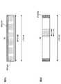
図2は、マシン通信端末の下り受信性能と上り送信性能を説明するための図である。図2Aにマシン通信端末の下り受信性能を示す。MTC−UE10Cは、LTE−UE10A、10Bと同様に、20MHzのシステム帯域に対応可能な受信性能を備えていることが示されている。つまり、MTC−UE10Cは、LTE−UE10A、10Bと同様に20MHzの全帯域に亘りPDCCHを受信して復号し、復号したPDCCHに含まれた下りリンク制御情報に基づいてPDSCHを受信する。 FIG. 2 is a diagram for explaining the downlink reception performance and uplink transmission performance of the machine communication terminal. FIG. 2A shows the downlink reception performance of the machine communication terminal. It is shown that MTC-UE10C is equipped with the reception performance which can respond | correspond to the system band of 20 MHz similarly to LTE-UE10A, 10B. That is, the MTC-
図2Bにマシン通信端末の上り受信性能を示す。MTC−UE10Cは、上りリンクで対応可能な帯域が、LTE−UE10A、10Bの上りリンクの通信可能な帯域(20MHz)と同じか,それに比べて、より狭い帯域に制限されている。LTE−UE10A、10Bは、MTC−UE10Cは上りリンクの帯域が制限されている場合、システム帯域(20MHz)の両端に配置したPUCCHで上り制御信号を送信するが、MTC−UE10CはPUSCH_MTCの両端にPUCCHは配置されない。PUCCHによって、ハイブリッドARQの応答確認、下りリンクのチャネル依存スケジューリングを補助するCQI、の上りリンクデータ送信のためのリソース要求が送信されるが、MTC−UE10CはPUSCHでこれらの信号を送信する。 FIG. 2B shows the uplink reception performance of the machine communication terminal. In the MTC-
LTEシステムに対する影響を抑えるために、MTC−UE10C用のPUSCHのサイズは、LTEシステムでサポートする1.4MHz、3MHz、5MHz、10MHz、15MHzのいずれかが望ましい。または、PRACHの帯域に相当する1.08MHzの帯域幅が適用されても良い。ただし、適用される帯域幅はこれに限られない。 In order to suppress the influence on the LTE system, the size of the PUSCH for the MTC-
上述したように、MTCシステムでの要求条件は、下りリンクで118.4kbps、上りリンクで59.2kbpsのように低いピークデータレートとなっている。また、MTCシステムにおけるMTC−UEは、通信環境が逐次変化するものではない。このため、無線基地局装置は、MTC−UEに対しては、下りリンク信号を送信するフレーム期間を制限することで、MTC−UEでの受信処理時間や信号処理時間を少なくことができる。これにより、MTC−UEにおけるバッテリー消費を抑えることができ、MTC−UEに要求されるコストを低減することができる。 As described above, the requirement conditions in the MTC system are low peak data rates such as 118.4 kbps in the downlink and 59.2 kbps in the uplink. In addition, in the MTC-UE in the MTC system, the communication environment does not change sequentially. For this reason, the radio base station apparatus can reduce the reception processing time and signal processing time in the MTC-UE by limiting the frame period for transmitting the downlink signal to the MTC-UE. Thereby, the battery consumption in MTC-UE can be suppressed and the cost requested | required of MTC-UE can be reduced.
本発明においては、MTC−UEは、無線基地局装置で制限されたフレーム期間について下りリンク信号(所定の周期で送信された下りリンク信号)を受信する。このとき、MTC−UEは、所定の周期のフレーム期間のみ下りリンク信号を監視する。すなわち、MTC−UEは、無線基地局装置から所定の周期のフレーム期間で送信された下りリンク信号について、その所定の周期のフレーム期間を監視し、そのフレーム期間で信号処理(復調、復号等の信号処理)を行う。言い換えると、所定の周期のフレーム期間以外では、下りリンク信号の復調、復号等の信号処理(PDCCHのブラインド復号を含む)は行わない。このように、信号処理期間を少なくすることにより、すべてのフレーム期間で信号処理をする場合に比べてMTC−UEにおけるバッテリー消費を抑えることができ、MTC−UEに要求されるコストを低減することができる。 In the present invention, the MTC-UE receives a downlink signal (a downlink signal transmitted at a predetermined period) for a frame period limited by the radio base station apparatus. At this time, the MTC-UE monitors the downlink signal only during a frame period of a predetermined period. That is, the MTC-UE monitors the frame period of the predetermined period for the downlink signal transmitted from the radio base station apparatus in the frame period of the predetermined period, and performs signal processing (demodulation, decoding, etc.) in the frame period. Signal processing). In other words, signal processing (including blind decoding of PDCCH) such as demodulation and decoding of the downlink signal is not performed outside the frame period of a predetermined period. Thus, by reducing the signal processing period, battery consumption in the MTC-UE can be suppressed as compared with the case where signal processing is performed in all frame periods, and the cost required for the MTC-UE is reduced. Can do.
ここで、無線基地局装置から下りリンク信号を送信するフレーム期間とは、例えば、サブフレーム、無線フレーム等を意味する。また、下りリンク信号としては、PDCCH信号、PDSCH信号等の信号が挙げられる。 Here, the frame period for transmitting a downlink signal from the radio base station apparatus means, for example, a subframe, a radio frame, or the like. Moreover, as a downlink signal, signals, such as a PDCCH signal and a PDSCH signal, are mentioned.
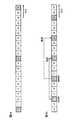
所定の周期としては、例えば、システムフレーム番号(SFN)(0−1023)を用いて決定することができる。具体的には、以下の式(1)を用いて所定の周期を決定することができる。
図3Aは、上記式(1)において、N=10、M=0の場合を示す図である。図3Aにおける横軸は時間方向を示しており、一つの期間単位はサブフレームを示している。また、サブフレームに付与されている番号がSFNである。したがって、図3Aに示す設定においては、無線基地局装置が、10サブフレーム毎に、下りリンク信号をMTC−UEに送信し、MTC−UEは、10サブフレーム毎に下りリンク信号を受信し図3Aに示す斜線部分のサブフレームを受信し)、この下りリンク信号を復調、復号する。 FIG. 3A is a diagram showing a case where N = 10 and M = 0 in the above formula (1). The horizontal axis in FIG. 3A indicates the time direction, and one period unit indicates a subframe. Further, the number assigned to the subframe is SFN. Therefore, in the configuration illustrated in FIG. 3A, the radio base station apparatus transmits a downlink signal to the MTC-UE every 10 subframes, and the MTC-UE receives the downlink signal every 10 subframes. 3A), the downlink signal is demodulated and decoded.
無線基地局装置からMTC−UEに対して下りリンク信号が送られる周期(式(1)におけるMやN)は、標準仕様で予め決定しておくか、無線基地局装置で決定することができる。この周期を無線基地局装置で決定する場合においては、無線基地局装置が、例えば上記式(1)を用いて決定する。なお、Nの下限値は、MTC−UEの性能によって決まるので、ある程度大きく設定しておくことが望ましい。そして、無線基地局装置は、決定した周期でMTC−UEに対して下りリンク信号を送信するように無線リソースに割り当てる。 The period (M or N in Equation (1)) in which the downlink signal is transmitted from the radio base station apparatus to the MTC-UE can be determined in advance by the standard specification or can be determined by the radio base station apparatus. . When this period is determined by the radio base station apparatus, the radio base station apparatus determines, for example, using the above equation (1). Since the lower limit value of N is determined by the performance of the MTC-UE, it is desirable to set it to a certain extent. And a radio base station apparatus allocates to a radio | wireless resource so that a downlink signal may be transmitted with respect to MTC-UE with the determined period.
また、この周期を無線基地局装置で決定する場合には、MTC−UEに対して下りリンク信号が送られる周期(式(1)におけるMやN)を含む周期に関する情報を、無線基地局装置からハイヤレイヤシグナリングでMTC−UEに通知しても良い。 In addition, when this period is determined by the radio base station apparatus, information on the period including the period (M or N in Expression (1)) in which the downlink signal is transmitted to the MTC-UE is used as the radio base station apparatus. To MTC-UE by higher layer signaling.
下りリンク信号が送られる周期については、MTC−UEの端末能力に依存すると考えられるので、この周期については、MTC−UEが自装置の端末能力情報を無線基地局装置にハイヤレイヤシグナリングで通知し、無線基地局装置が端末能力情報に基づいて周期を決定しても良い。例えば、MTC−UEが自装置のカテゴリを無線基地局装置に通知し、そのカテゴリに応じて(例えば、カテゴリ0であれば)本制御における所定の周期で下りリンク信号を無線リソースに割り当てる。 Since it is considered that the cycle in which the downlink signal is transmitted depends on the terminal capability of the MTC-UE, the MTC-UE notifies the radio base station device of the terminal capability information of its own device by higher layer signaling. The radio base station apparatus may determine the period based on the terminal capability information. For example, the MTC-UE notifies the radio base station apparatus of its own category, and assigns a downlink signal to a radio resource at a predetermined period in this control according to the category (for example, if it is category 0).
このように、無線基地局装置が所定の周期で下りリンク信号を送信する制御を行う場合においては、通信開始時等で同期信号(Primary Synchronization Signal/Secondary Synchronization Signal)をMTC−UEに通知する必要があるので、このような通信に必要となる情報(同期信号の送信位置等の情報)は、ハイヤレイヤシグナリングで無線基地局装置からMTC−UEに通知することが望ましい。 As described above, when the radio base station apparatus performs control to transmit a downlink signal at a predetermined cycle, it is necessary to notify the MTC-UE of a synchronization signal (Primary Synchronization Signal / Secondary Synchronization Signal) at the start of communication or the like. Therefore, it is desirable to notify the MTC-UE of information necessary for such communication (information such as the transmission position of the synchronization signal) from the radio base station apparatus by higher layer signaling.
本制御において、所定の周期の整数倍とハイブリッドARQ(Automatic Repeat reQuest:HARQ)の周期とが同じであることが望ましい。例えば、図3Bでは、所定の周期が4サブフレームであり、4サブフレーム毎にMTC−UEに対して下りリンク信号が割り当てられる。すなわち、所定の周期の2倍がHARQの周期と同じになる(N=8、M=0,4でM=0のときがHARQの周期と同じである)。このような割り当てに設定すると、例えば、SFN=12で再送要求(NAK#1)がされると、8サブフレーム後のSFN=20でNAK#1に対応するデータが再送される。また、SFN=16で再送要求(NAK#2)がされると、8サブフレーム後のSFN=24でNAK#2に対応するデータが再送される。SFN=20及びSFN=24は、MTC−UEに対して下りリンク信号が割り当てられる無線リソースであるので、MTC−UEは割り当てられないサブフレームを使用することなく(監視することなく)、再送を受信することができる。このため、データを格納しておくソフトバッファ領域(メモリ領域)を少なくする(HARQプロセス数を少なくする)ことができる。図3Bの場合においては、HARQプロセス数を2(Mの数分)にすることができる。これにより、MTC−UEにおけるメモリ領域を低減させることができ、MTC−UEに要求されるコストを低減することができる。 In this control, it is desirable that the integer multiple of the predetermined cycle and the cycle of hybrid ARQ (Automatic Repeat reQuest: HARQ) be the same. For example, in FIG. 3B, the predetermined period is 4 subframes, and a downlink signal is assigned to the MTC-UE every 4 subframes. That is, twice the predetermined period is the same as the HARQ period (when N = 8, M = 0, 4 and M = 0, the HARQ period is the same). When such allocation is set, for example, when a retransmission request (NAK # 1) is made with SFN = 12, data corresponding to NAK # 1 is retransmitted with SFN = 20 after 8 subframes. When a retransmission request (NAK # 2) is made with SFN = 16, data corresponding to NAK # 2 is retransmitted with SFN = 24 after 8 subframes. Since SFN = 20 and SFN = 24 are radio resources to which downlink signals are allocated to the MTC-UE, the MTC-UE performs retransmission without using (not monitoring) an unassigned subframe. Can be received. Therefore, it is possible to reduce the soft buffer area (memory area) for storing data (reduce the number of HARQ processes). In the case of FIG. 3B, the number of HARQ processes can be 2 (the number of M). Thereby, the memory area | region in MTC-UE can be reduced and the cost requested | required of MTC-UE can be reduced.
この場合において、ソフトバッファ領域はMTC−UEの端末能力に依存すると考えられるので、所定の周期については、MTC−UEが自装置の端末能力情報(ソフトバッファ領域)を無線基地局装置にハイヤレイヤシグナリングで通知し、無線基地局装置が端末能力情報に基づいて周期を決定しても良い。 In this case, since it is considered that the soft buffer area depends on the terminal capability of the MTC-UE, the MTC-UE transmits its own terminal capability information (soft buffer area) to the radio base station apparatus for a predetermined period. Notification may be made by signaling, and the radio base station apparatus may determine the period based on the terminal capability information.
図4を参照しながら、本実施の形態に係る無線基地局装置20の全体構成について説明する。無線基地局装置20は、MTC−UEとマシン通信すると共に、ユーザ端末(LTE−UE)と信号通信のために無線接続する。無線基地局装置20は、送受信アンテナ201と、アンプ部202と、送受信部203と、ベースバンド信号処理部204と、呼処理部205と、伝送路インターフェース206とを備えている。 The overall configuration of radio
無線基地局装置20からユーザ端末10へ下りリンクで送信されるユーザデータは、無線基地局装置20の上位局装置30から伝送路インターフェース206を介してベースバンド信号処理部204に入力される。 User data transmitted from the radio
ベースバンド信号処理部204は、シーケンス番号付与等のPDCPレイヤの処理、ユーザデータの分割・結合、RLC(Radio Link Control)再送制御の送信処理などのRLCレイヤの送信処理、MAC(Medium Access Control)再送制御、例えば、HARQの送信処理、スケジューリング、伝送フォーマット選択、チャネル符号化、逆高速フーリエ変換(IFFT:Inverse Fast Fourier Transform)処理、プリコーディング処理を行う。 The baseband
ベースバンド信号処理部204は、さらにユーザ端末10に対してセル50における無線通信のための制御情報を報知チャネルで通知する。セル50における通信のための報知情報には、例えば、上りリンク又は下りリンクにおけるシステム帯域幅や、PRACHにおけるランダムアクセスプリアンブルの信号を生成するためのルート系列の識別情報(Root Sequence Index)等が含まれる。 The baseband
送受信部203は、ベースバンド信号処理部204から出力されたベースバンド信号を無線周波数帯に周波数変換処する。RF信号は、アンプ部202で増幅されて送受信アンテナ201へ出力される。送受信部203は、MTC−UEに対しては、上述した所定の周期で下りリンク信号を送信する。 The transmission /
無線基地局装置20は、ユーザ端末10が送信した送信波を送受信アンテナ201で受信する。送受信アンテナ201で受信された無線周波数信号がアンプ部202で増幅され、送受信部203で周波数変換されてベースバンド信号に変換され、ベースバンド信号処理部204に入力される。 The radio
ベースバンド信号処理部204は、上りリンクで受信したベースバンド信号に含まれるユーザデータに対して、FFT(Fast Fourier Transform)処理、IDFT(Inverse Discrete Fourier Transform)処理、誤り訂正復号、MAC再送制御の受信処理、RLCレイヤ、PDCPレイヤの受信処理を行う。復号された信号は伝送路インターフェース206を介して上位局装置30に転送される。 The baseband
呼処理部205は、通信チャネルの設定や解放等の呼処理や、無線基地局装置20の状態管理や、無線リソースの管理を行う。 The
図5は、本実施の形態に係る無線基地局装置20が有するベースバンド信号処理部204の機能ブロック図である。無線基地局装置20と無線接続するユーザ端末10に対する送信データが上位局装置30から無線基地局装置20に対して転送される。 FIG. 5 is a functional block diagram of baseband
制御情報生成部302は、ハイヤレイヤシグナリング(例えばRRCシグナリング)する上位制御信号をユーザ単位で生成する。データ生成部301は、上位局装置30から転送された送信データをユーザ別にユーザデータとして出力する。 The control
ベースバンド信号処理部204は、チャネル符号化部303、変調部304、マッピング部305を備えている。チャネル符号化部303は、データ生成部301から出力されるユーザデータで構成される共有データチャネル(PDSCH)を、ユーザ毎にチャネル符号化する。変調部304は、チャネル符号化されたユーザデータをユーザ毎に変調する。マッピング部305は、変調されたユーザデータを無線リソースにマッピングする。 The baseband
また、ベースバンド信号処理部204は、ユーザ固有の下り制御情報である下り共有データチャネル用制御情報を生成する下り制御情報生成部306と、ユーザ共通の下り制御情報である下り共通制御チャネル用制御情報を生成する下り共通チャネル用制御情報生成部307とを備えている。下り制御情報生成部306は、ユーザ毎に決定したリソース割り当て情報、MCS情報、HARQ用の情報、PUCCHの送信電力制御コマンド等から構成された下りリンク制御情報を生成する。 Also, the baseband
ベースバンド信号処理部204は、チャネル符号化部308、変調部309を備えている。チャネル符号化部308は、下り制御情報生成部306及び下り共通チャネル用制御情報生成部307で生成される制御情報をユーザ毎にチャネル符号化する。変調部309は、チャネル符号化された下り制御情報を変調する。 The baseband
また、ベースバンド信号処理部204は、上り共有データチャネル(PUSCH)を制御する上り共有データチャネル用制御情報をユーザ毎に生成する上り制御情報生成部311と、生成した上り共有データチャネル用制御情報をユーザ毎にチャネル符号化するチャネル符号化部312と、チャネル符号化した上り共有データチャネル用制御情報をユーザ毎に変調する変調部313とを備える。 Further, the baseband
参照信号生成部318は、チャネル推定、シンボル同期、CQI測定、モビリティ測定等の様々な目的に使用されるセル固有参照信号(CRS:Cell−specific Reference Signal)をリソースブロック(RB)内にFDM/TDMで多重して送信する。また、参照信号生成部318は、下りリンク復調用参照信号(UE specific RS)を送信する。 The reference
上記変調部309、313でユーザ毎に変調された下り/上り制御情報は、制御チャネル多重部314で多重され、さらにインタリーブ部315でインタリーブされる。インタリーブ部315から出力される制御信号及びマッピング部305から出力されるユーザデータは下りチャネル信号としてIFFT部316へ入力される。また、下り参照信号がIFFT部316へ入力される。IFFT部316は、下りチャネル信号及び下り参照信号を逆高速フーリエ変換して周波数領域の信号から時系列の信号に変換する。サイクリックプレフィックス(CP)挿入部317は、下りチャネル信号の時系列信号にサイクリックプレフィックスを挿入する。なお、サイクリックプレフィックスは、マルチパス伝搬遅延の差を吸収するためのガードインターバルとして機能する。サイクリックプレフィックスが付加された送信データは、送受信部203に送出される。 The downlink / uplink control information modulated for each user by the
スケジューリング部310は、リソース割り当てを制御する。スケジューリング部310は、上位局装置30から送信データ及び再送指示が入力されると共に、上りリンクの受信信号を測定した受信部からチャネル推定値やリソースブロックのCQIが入力される。スケジューリング部310は、上位局装置30から入力された再送指示、チャネル推定値及びCQIを参照しながら、下りリンク割当て情報、上りリンク割当て情報、及び上下共有チャネル信号のスケジューリングを行う。移動通信における伝搬路は、周波数選択性フェージングにより周波数ごとに変動が異なる。そこで、ユーザデータ送信時に、ユーザ端末10に対してサブフレーム毎に通信品質の良好なリソースブロックを割り当てる(適応周波数スケジューリングと呼ばれる)。適応周波数スケジューリングでは、各リソースブロックに対して伝搬路品質の良好なユーザ端末10を選択して割り当てる。そのため、スケジューリング部310は、各ユーザ端末10からフィードバックされるリソースブロック毎のCQIを用いてスループットの改善が期待されるリソースブロックを割り当てる。また、割り当てたリソースブロックで所定のブロック誤り率を満たすMCS(符号化率、変調方式)を決定する。スケジューリング部310が決定したMCS(符号化率、変調方式)を満足するパラメータがチャネル符号化部303、308、312、変調部304、309、313に設定される。 The
スケジューリング部310は、LTE−UEとMTC−UEとを区別してスケジューリングを行う。スケジューリング部310は、MTC−UEに対して所定の周期で下りリンク信号を割り当てる。この所定の周期については、無線基地局装置側で決定した周期でも良く、予め決められた周期でも良く、MTC−UEから通知された端末能力情報等に応じて無線基地局装置側で決定した周期でも良い。所定の周期を決定する場合、所定の周期の整数倍とHARQの周期とが同じとなるように設定することにより、HARQプロセス数を少なくすることができる。なお、このように決められた所定の周期に関する情報は、ハイヤレイヤシグナリングでMTC−UEに通知される。 The
次に、図6を参照しながら、本実施の形態に係るユーザ端末10の全体構成について説明する。ユーザ端末10は、複数の送受信アンテナ101と、アンプ部102と、送受信部103と、ベースバンド信号処理部104と、アプリケーション部105とを備えている。 Next, the overall configuration of the
送受信アンテナ101で受信した無線周波数信号がアンプ部102で増幅され、送受信部103で周波数変換されてベースバンド信号に変換される。このベースバンド信号は、ベースバンド信号処理部104でFFT処理や、誤り訂正復号、再送制御の受信処理等がなされる。この下りリンクのデータの内、下りリンクのユーザデータは、アプリケーション部105に転送される。アプリケーション部105は、物理レイヤやMACレイヤより上位のレイヤに関する処理等を行う。また、下りリンクのデータの内、報知情報も、アプリケーション部105に転送される。 A radio frequency signal received by the transmission /
一方、上りリンクのユーザデータは、アプリケーション部105からベースバンド信号処理部104に入力される。ベースバンド信号処理部104は、再送制御(HARQ)の送信処理や、チャネル符号化、DFT(Discrete Fourier Transform)処理、IFFT処理を行う。送受信部103は、ベースバンド信号処理部104から出力されたベースバンド信号を無線周波数帯に変換する。その後、アンプ部102で増幅されて送受信アンテナ101より送信される。送受信部103は、必要に応じて、端末能力情報(メモリ領域情報、カテゴリ情報等)をハイヤレイヤシグナリングで無線基地局装置に通知する。 On the other hand, uplink user data is input from the
図7は、MTC−UE10が有するベースバンド信号処理部104の機能ブロック図である。
無線基地局装置20から受信データとして受信された下りリンク信号は、CP除去部401でCPが除去される。CPが除去された下りリンク信号は、FFT部402へ入力される。FFT部402は、下りリンク信号を高速フーリエ変換(FFT:Fast Fourier Transform)して時間領域の信号から周波数領域の信号に変換し、デマッピング部403へ入力する。デマッピング部403は、下りリンク信号をデマッピングし、下りリンク信号から複数の制御情報が多重された多重制御情報、ユーザデータ、上位制御信号を取り出す。なお、デマッピング部403によるデマッピング処理は、アプリケーション部105から入力される上位制御信号に基づいて行われる。デマッピング部403から出力された多重制御情報は、デインタリーブ部404でデインタリーブされる。FIG. 7 is a functional block diagram of the baseband
The
また、ベースバンド信号処理部104は、下り/上り制御情報を復調する制御情報復調部405、下り共有データを復調するデータ復調部406及びチャネル推定部407を備えている。制御情報復調部405は、下り制御チャネルから下り共通制御チャネル用制御情報を復調する共通制御チャネル用制御情報復調部405aと、下り制御チャネルからサーチスペースをブラインドデコーディングして上り共有データチャネル用制御情報を復調する上り共有データチャネル用制御情報復調部405bと、下り制御チャネルからサーチスペースをブラインドデコーディングして下り共有データチャネル用制御情報を復調する下り共有データチャネル用制御情報復調部405cとを備えている。データ復調部406は、ユーザデータ及び上位制御信号を復調する下り共有データ復調部406aと、下り共有チャネルデータを復調する下り共有チャネルデータ復調部406bとを備えている。 The baseband
共通制御チャネル用制御情報復調部405aは、下り制御チャネル(PDCCH)の共通サーチスペースのブラインドデコーディング処理、復調処理、チャネル復号処理などによりユーザ共通の制御情報である共通制御チャネル用制御情報を取り出す。共通制御チャネル用制御情報は、下りリンクのチャネル品質情報(CQI)を含んでおり、後述するマッピング部115に入力され、無線基地局装置20への送信データの一部としてマッピングされる。 The common control channel
上り共有データチャネル用制御情報復調部405bは、下り制御チャネル(PCCCH)のユーザ個別サーチスペースのブラインドデコーディング処理、復調処理、チャネル復号処理などによりユーザ固有の上り制御情報を取り出す。復調された下り制御情報は、下り共通チャネルデータ復調部406bへ入力されて上り共有データチャネル(PUSCH)の制御に使用される。 The uplink shared data channel
下り共有データチャネル用制御情報復調部405cは、下り制御チャネル(PDCCH)のユーザ個別サーチスペースのブラインドデコーディング処理、復調処理、チャネル復号処理などによりユーザ固有の下り制御信号である下り共有データチャネル用制御情報を取り出す。復調された下り共有データチャネル用制御情報は、下り共有データ復調部406へ入力されて、下り共有データチャネル(PDSCH)の制御に使用される。 The downlink shared data channel
下り共有データ復調部406aは、下り共有データチャネル用制御情報復調部405cから入力された下り共有データチャネル用制御情報に基づいて、ユーザデータや上位制御情報を取得する。上位制御情報(モード情報を含む)は、チャネル推定部407に出力される。下り共通チャネルデータ復調部406bは、上り共有データチャネル用制御情報復調部405bから入力された上り共有データチャネル用制御情報に基づいて、上り共通チャネルデータを復調する。 The downlink shared
チャネル推定部407は、ユーザ端末固有の参照信号,または共通参照信号を用いてチャネル推定する。推定されたチャネル変動を、共通制御チャネル用制御情報復調部405a、上り共有データチャネル用制御情報復調部405b、下り共有データチャネル用制御情報復調部405c及び下り共有データ復調部406aに出力する。これらの復調部においては、推定されたチャネル変動及び復調用参照信号を用いて下りリンク割当て情報を復調する。 The
上記制御情報復調部405は、所定の周期で無線基地局装置から送信される下りリンク信号における制御情報を復調する。上記データ復調部406は、所定の周期で無線基地局装置から送信される下りリンク信号におけるデータを復調する。したがって、所定の周期で無線基地局装置から送信されるフレーム期間以外のフレーム期間では、制御情報やデータの復調は行わない。なお、この所定の周期に関する情報は、無線基地局装置からハイヤレイヤシグナリングで通知される。 The control
ベースバンド信号処理部104は、送信処理系の機能ブロックとして、データ生成部408、チャネル符号化部409、変調部410、DFT部411、マッピング部412、IFFT部413、CP挿入部414を備えている。データ生成部408は、アプリケーション部105から入力されるビットデータから送信データを生成する。チャネル符号化部409は、送信データに対して誤り訂正等のチャネル符号化処理を施し、変調部410はチャネル符号化された送信データをQPSK等で変調する。DFT部411は、変調された送信データを離散フーリエ変換する。マッピング部412は、DFT後のデータシンボルの各周波数成分を、無線基地局装置20に指示されたサブキャリア位置へマッピングする。IFFT部413は、システム帯域に相当する入力データを逆高速フーリエ変換して時系列データに変換し、CP挿入部414は時系列データに対してデータ区切りでサイクリックプレフィックスを挿入する。 The baseband
一方、上りリンクのユーザデータについては、アプリケーション部105からベースバンド信号処理部104に入力される。ベースバンド信号処理部104では、再送制御の送信処理や、チャネル符号化、プリコーディング、DFT処理、IFFT処理等が行われて送受信部106に転送される。送受信部106では、ベースバンド信号処理部104から出力されたベースバンド信号を無線周波数帯に変換する周波数変換処理が施され、その後、アンプ部102で増幅されて送受信アンテナ101より送信される。 On the other hand, uplink user data is input from the
上記構成のシステムにおいては、無線基地局装置は、スケジューリング部310でMTC−UEに対して所定の周期で下りリンク信号を割り当て、割り当てられた下りリンク信号を送受信部203でMTC−UEに送信する。MTC−UEには、この所定の周期に関する情報がハイヤレイヤシグナリングで通知されている。MTC−UEは、所定の周期で無線基地局装置からの下りリンク信号を受信し、この下りリンク信号を復調する。なお、この所定の周期については、無線基地局装置側で決定した周期でも良く、予め決められた周期でも良く、MTC−UEから通知された端末能力情報等に応じて無線基地局装置側で決定した周期でも良い。これにより、MTCシステムのネットワークドメインにLTEシステムを採用する場合に、MTC−UEに要求されるコストを低減することができる。 In the system configured as described above, the radio base station apparatus allocates a downlink signal to the MTC-UE at a predetermined period by the
以上、上述の実施形態を用いて本発明について詳細に説明したが、当業者にとっては、本発明が本明細書中に説明した実施形態に限定されるものではないということは明らかである。本発明は、特許請求の範囲の記載により定まる本発明の趣旨及び範囲を逸脱することなく修正及び変更態様として実施することができる。従って、本明細書の記載は、例示説明を目的とするものであり、本発明に対して何ら制限的な意味を有するものではない。 Although the present invention has been described in detail using the above-described embodiments, it is obvious to those skilled in the art that the present invention is not limited to the embodiments described in this specification. The present invention can be implemented as modified and changed modes without departing from the spirit and scope of the present invention defined by the description of the scope of claims. Therefore, the description of the present specification is for illustrative purposes and does not have any limiting meaning to the present invention.
1 無線通信システム
10A、10B LTE−UE
10C MTC−UE
20 無線基地局装置
30 上位局装置
40 コアネットワーク
101 送受信アンテナ
102 アンプ部
103 送受信部
104 ベースバンド信号処理部
105 アプリケーション部
201 送受信アンテナ
202 アンプ部
203 送受信部
204 ベースバンド信号処理部
205 呼処理部
206 伝送路インターフェース
301 データ生成部
302 制御情報生成部
303、308、312 チャネル符号化部
304、309、313 変調部
305 マッピング部
306 下り制御情報生成部
307 下り共通チャネル用制御情報生成部
310 スケジューリング部
311 上り制御情報生成部
314 制御チャネル多重部
315 インタリーブ部
316 IFFT部
317 CP挿入部
318 参照信号生成部
401 CP除去部
402 FFT部
403 デマッピング部
404 デインタリーブ部
405 制御情報復調部
405a 共通制御チャネル用制御情報復調部
405b 上り共有データチャネル用制御情報復調部
405c 下り共有データチャネル用制御情報復調部
406 データ復調部
406a 下り共有データ復調部
406b 下り共有チャネルデータ復調部
407 チャネル推定部
408 データ生成部
409 チャネル符号化部
410 変調部
411 DFT部
412 マッピング部
413 IFFT部
414 CP挿入部1
10C MTC-UE
DESCRIPTION OF
Claims (11)
Translated fromJapanese前記無線基地局装置は、前記マシン通信端末に対して所定の周期で下りリンク信号を割り当てる割当部と、割り当てられた下りリンク信号を前記マシン通信端末に送信する送信部と、を有し、
前記マシン通信端末は、前記所定の周期で前記無線基地局装置からの下りリンク信号を受信する受信部と、前記所定の周期で受信した下りリンク信号を復調する復調部と、を有し、
前記マシン通信端末は、自装置の端末能力情報として、ソフトバッファ領域及びカテゴリの少なくとも1つに関する情報を前記無線基地局装置に通知し、
前記無線基地局装置は、前記端末能力情報に基づいて前記所定の周期を決定することを特徴とする無線通信システム。A wireless communication system including a wireless base station device and a machine communication terminal that performs machine communication with the wireless base station device,
The radio base station apparatus includes an assigning unit that assigns a downlink signal to the machine communication terminal at a predetermined cycle, and a transmission unit that transmits the assigned downlink signal to the machine communication terminal,
The machine communication terminal includes a receiving unit that receives a downlink signal from the radio base station apparatus at the predetermined period, and a demodulating unit that demodulates the downlink signal received at the predetermined period,
The machine communication terminal, as the terminal capability information of the own apparatus, and notifies information related to at least one of the soft buffer territoryIki及 beauty category to the radio base station apparatus,
The radio base station apparatus determines the predetermined period based on the terminal capability information.
前記マシン通信端末から通知される端末能力情報に基づいて前記所定の周期を決定し、
前記端末能力情報は、ソフトバッファ領域及びカテゴリの少なくとも1つに関する情報であることを特徴とする無線基地局装置。An allocation unit that allocates a downlink signal to a machine communication terminal that performs machine communication at a predetermined period; and a transmission unit that transmits the allocated downlink signal to the machine communication terminal,
Determining the predetermined period based on terminal capability information notified from the machine communication terminal;
The terminal capability information, the radio base station and wherein the at least one information about the soft buffer territoryIki及 beauty category.
前記所定の周期で受信した下りリンク信号を復調する復調部と、
自装置の端末能力情報として、ソフトバッファ領域及びカテゴリの少なくとも1つに関する情報を前記無線基地局装置に通知する送信部と、を具備し、
前記所定の周期は、前記無線基地局装置によって、前記端末能力情報に基づいて決定されることを特徴とするマシン通信端末。A receiver that receives information on a predetermined period and receives a downlink signal from the radio base station apparatus at the predetermined period;
A demodulator that demodulates a downlink signal received at the predetermined period;
As the terminal capability information of the own device, information about at least one soft buffer territoryIki及 beauty categoryanda transmission unit configured to notify the radio base stationapparatus,
The predetermined period is determined by the radio base station apparatus based on the terminal capability information .
前記無線基地局装置において、前記マシン通信端末に対して所定の周期で下りリンク信号を割り当てる工程と、割り当てられた下りリンク信号を前記マシン通信端末に送信する工程と、
前記マシン通信端末において、前記所定の周期で前記無線基地局装置からの下りリンク信号を受信する工程と、前記所定の周期で受信した下りリンク信号を復調する工程と、を有し、
前記マシン通信端末において、自装置の端末能力情報として、ソフトバッファ領域及びカテゴリの少なくとも1つに関する情報を前記無線基地局装置に通知し、
前記無線基地局装置において、前記端末能力情報に基づいて前記所定の周期を決定することを特徴とする無線通信方法。A wireless communication method in a wireless communication system including a wireless base station device and a machine communication terminal that performs machine communication with the wireless base station device,
In the radio base station apparatus, a step of assigning a downlink signal to the machine communication terminal at a predetermined cycle, a step of transmitting the assigned downlink signal to the machine communication terminal,
In the machine communication terminal, the step of receiving a downlink signal from the radio base station apparatus at the predetermined period, and the step of demodulating the downlink signal received at the predetermined period,
In the machine communication terminal, as the terminal capability information of the own apparatus, and notifies information related to at least one of the soft buffer territoryIki及 beauty category to the radio base station apparatus,
The wireless base station apparatus, wherein the predetermined period is determined based on the terminal capability information.
Priority Applications (4)
| Application Number | Priority Date | Filing Date | Title |
|---|---|---|---|
| JP2011224343AJP5918497B2 (en) | 2011-10-11 | 2011-10-11 | Radio communication system, radio base station apparatus, machine communication terminal, and radio communication method |
| PCT/JP2012/070887WO2013054591A1 (en) | 2011-10-11 | 2012-08-17 | Wireless communication system, wireless base station device, machine-to-machine communication terminal, and wireless communication method |
| EP12840021.5AEP2768261A4 (en) | 2011-10-11 | 2012-08-17 | Wireless communication system, wireless base station device, machine-to-machine communication terminal, and wireless communication method |
| US14/349,441US20140235256A1 (en) | 2011-10-11 | 2012-08-17 | Radio communication system, radio base station apparatus, machine communication terminal and radio communication method |
Applications Claiming Priority (1)
| Application Number | Priority Date | Filing Date | Title |
|---|---|---|---|
| JP2011224343AJP5918497B2 (en) | 2011-10-11 | 2011-10-11 | Radio communication system, radio base station apparatus, machine communication terminal, and radio communication method |
Publications (2)
| Publication Number | Publication Date |
|---|---|
| JP2013085152A JP2013085152A (en) | 2013-05-09 |
| JP5918497B2true JP5918497B2 (en) | 2016-05-18 |
Family
ID=48081651
Family Applications (1)
| Application Number | Title | Priority Date | Filing Date |
|---|---|---|---|
| JP2011224343AActiveJP5918497B2 (en) | 2011-10-11 | 2011-10-11 | Radio communication system, radio base station apparatus, machine communication terminal, and radio communication method |
Country Status (4)
| Country | Link |
|---|---|
| US (1) | US20140235256A1 (en) |
| EP (1) | EP2768261A4 (en) |
| JP (1) | JP5918497B2 (en) |
| WO (1) | WO2013054591A1 (en) |
Families Citing this family (11)
| Publication number | Priority date | Publication date | Assignee | Title |
|---|---|---|---|---|
| JP6172280B2 (en)* | 2013-08-07 | 2017-08-02 | 富士通株式会社 | Wireless communication system, base station, communication terminal, and wireless communication method |
| US20160205628A1 (en)* | 2013-08-20 | 2016-07-14 | Kyocera Corporation | Mobile communication method, radio terminal, and radio base station |
| JP6298263B2 (en)* | 2013-09-26 | 2018-03-20 | 株式会社Nttドコモ | Wireless base station, user terminal, and wireless communication method |
| GB2519804A (en) | 2013-10-31 | 2015-05-06 | Nec Corp | Power saving in mobile radio communications device |
| US20160050513A1 (en)* | 2014-08-15 | 2016-02-18 | Aviacomm Inc. | Rf front-end architecture for machine-to-machine applications |
| US10575205B2 (en) | 2014-10-20 | 2020-02-25 | Qualcomm Incorporated | Transport block size determination |
| WO2016114544A1 (en)* | 2015-01-12 | 2016-07-21 | 엘지전자 주식회사 | Method for transmitting dmrs for narrow band transmission, and mtc device |
| RU2017125230A (en) | 2015-01-29 | 2019-02-28 | Нтт Докомо, Инк. | TERMINAL AND COMMUNICATION SYSTEM |
| US10470200B2 (en)* | 2016-06-16 | 2019-11-05 | Qualcomm Incorporated | Low complexity higher order MIMO |
| US10313083B2 (en) | 2016-09-30 | 2019-06-04 | Telefonaktiebolaget Lm Ericsson (Publ) | Method for hybrid automatic repeat request process, network device and terminal device |
| US11601820B2 (en)* | 2017-01-27 | 2023-03-07 | Qualcomm Incorporated | Broadcast control channel for shared spectrum |
Family Cites Families (12)
| Publication number | Priority date | Publication date | Assignee | Title |
|---|---|---|---|---|
| US7283818B2 (en)* | 2004-01-23 | 2007-10-16 | Samsung Electronics Co., Ltd. | Apparatus and method using page response messages to change the slot cycle index of a selected mobile station in a wireless network |
| EP2290868B1 (en)* | 2004-11-03 | 2013-10-16 | Samsung Electronics Co., Ltd. | System for receiving hybrid automatic repeat request buffer capability information in broadband wireless access communication system |
| KR100615139B1 (en)* | 2005-10-18 | 2006-08-22 | 삼성전자주식회사 | Method and apparatus for allocating transmission period in wireless telecommunication system and therefor system |
| WO2007144956A1 (en)* | 2006-06-16 | 2007-12-21 | Mitsubishi Electric Corporation | Mobile communication system and mobile terminal |
| JP2008306267A (en)* | 2007-06-05 | 2008-12-18 | Sharp Corp | Mobile station apparatus, base station apparatus, communication system, program, and communication method |
| JP5245789B2 (en)* | 2008-12-12 | 2013-07-24 | 日本電気株式会社 | Mobile communication device and control method of mobile communication device |
| KR101127146B1 (en)* | 2008-12-19 | 2012-03-20 | 한국전자통신연구원 | Apparatus and mehtod for offering multimedia broadcast and multicast service in a wireless communication system |
| US8560696B2 (en)* | 2009-04-28 | 2013-10-15 | Intel Corporation | Transmission of advanced-MAP information elements in mobile networks |
| MX2012009268A (en)* | 2010-02-12 | 2012-11-12 | Interdigital Patent Holdings | Access control and congestion control in machine-to-machine communication. |
| WO2011119680A2 (en)* | 2010-03-23 | 2011-09-29 | Interdigital Patent Holdings, Inc. | Efficient signaling for machine type communication |
| EP2636174B1 (en)* | 2010-11-05 | 2018-10-17 | BlackBerry Limited | Harq soft bit buffer partitioning for carrier aggregation |
| KR102032848B1 (en)* | 2011-08-23 | 2019-10-16 | 엘지전자 주식회사 | Method of operating an harq buffer for a dynamic sub-frame change and an apparatus for same |
- 2011
- 2011-10-11JPJP2011224343Apatent/JP5918497B2/enactiveActive
- 2012
- 2012-08-17WOPCT/JP2012/070887patent/WO2013054591A1/enactiveApplication Filing
- 2012-08-17EPEP12840021.5Apatent/EP2768261A4/ennot_activeWithdrawn
- 2012-08-17USUS14/349,441patent/US20140235256A1/ennot_activeAbandoned
Also Published As
| Publication number | Publication date |
|---|---|
| EP2768261A1 (en) | 2014-08-20 |
| WO2013054591A1 (en) | 2013-04-18 |
| US20140235256A1 (en) | 2014-08-21 |
| JP2013085152A (en) | 2013-05-09 |
| EP2768261A4 (en) | 2015-06-03 |
Similar Documents
| Publication | Publication Date | Title |
|---|---|---|
| JP5918497B2 (en) | Radio communication system, radio base station apparatus, machine communication terminal, and radio communication method | |
| JP5847525B2 (en) | Wireless communication terminal, base station apparatus, wireless communication system, and wireless communication method | |
| JP6568066B2 (en) | Mobile station apparatus, base station apparatus, and method | |
| JP6105211B2 (en) | Base station apparatus, radio communication terminal, radio communication system, and radio communication method | |
| JP6388584B2 (en) | Terminal apparatus, base station apparatus, integrated circuit, and communication method | |
| JP6041295B2 (en) | Terminal device, base station device, and wireless communication method | |
| JP6394918B2 (en) | Terminal device, wireless communication method, and integrated circuit | |
| WO2014175003A1 (en) | Terminal apparatus, integrated circuit, and radio communication method | |
| JP2019216295A (en) | Base station device, terminal device, and communication method | |
| JPWO2014162914A1 (en) | Terminal device, integrated circuit, and wireless communication method | |
| WO2014162913A1 (en) | Terminal device, base station device, integrated circuit, and wireless communication method | |
| JP6635267B2 (en) | Terminal device and communication method | |
| JP6541008B2 (en) | Terminal device and communication method | |
| WO2015008830A1 (en) | Terminal device, base station device, integrated circuit, and wireless communication method | |
| JP2010045549A (en) | Mobile communication system, transmission device, reception device, and method | |
| WO2017195659A1 (en) | Terminal device, base station device, communication method and integrated circuit | |
| JPWO2016017672A1 (en) | TERMINAL DEVICE, BASE STATION DEVICE, COMMUNICATION METHOD, AND INTEGRATED CIRCUIT | |
| WO2017195660A1 (en) | Terminal device, base station device, communication method and integrated circuit | |
| JP6414752B2 (en) | Terminal device, base station device, integrated circuit, and wireless communication method | |
| EP3113537B1 (en) | Terminal device, integrated circuit, and radio communication method | |
| US9077532B2 (en) | User terminal and base station apparatus | |
| JP2015070342A (en) | Base station, terminal, and communication method |
Legal Events
| Date | Code | Title | Description |
|---|---|---|---|
| A621 | Written request for application examination | Free format text:JAPANESE INTERMEDIATE CODE: A621 Effective date:20141007 | |
| A131 | Notification of reasons for refusal | Free format text:JAPANESE INTERMEDIATE CODE: A131 Effective date:20150804 | |
| A521 | Request for written amendment filed | Free format text:JAPANESE INTERMEDIATE CODE: A523 Effective date:20151005 | |
| A131 | Notification of reasons for refusal | Free format text:JAPANESE INTERMEDIATE CODE: A131 Effective date:20151110 | |
| A521 | Request for written amendment filed | Free format text:JAPANESE INTERMEDIATE CODE: A523 Effective date:20160108 | |
| TRDD | Decision of grant or rejection written | ||
| A01 | Written decision to grant a patent or to grant a registration (utility model) | Free format text:JAPANESE INTERMEDIATE CODE: A01 Effective date:20160209 | |
| A601 | Written request for extension of time | Free format text:JAPANESE INTERMEDIATE CODE: A601 Effective date:20160308 | |
| R155 | Notification before disposition of declining of application | Free format text:JAPANESE INTERMEDIATE CODE: R155 | |
| A61 | First payment of annual fees (during grant procedure) | Free format text:JAPANESE INTERMEDIATE CODE: A61 Effective date:20160408 | |
| R150 | Certificate of patent or registration of utility model | Ref document number:5918497 Country of ref document:JP Free format text:JAPANESE INTERMEDIATE CODE: R150 | |
| R250 | Receipt of annual fees | Free format text:JAPANESE INTERMEDIATE CODE: R250 | |
| R250 | Receipt of annual fees | Free format text:JAPANESE INTERMEDIATE CODE: R250 | |
| R250 | Receipt of annual fees | Free format text:JAPANESE INTERMEDIATE CODE: R250 | |
| R250 | Receipt of annual fees | Free format text:JAPANESE INTERMEDIATE CODE: R250 | |
| R250 | Receipt of annual fees | Free format text:JAPANESE INTERMEDIATE CODE: R250 | |
| R250 | Receipt of annual fees | Free format text:JAPANESE INTERMEDIATE CODE: R250 | |
| R250 | Receipt of annual fees | Free format text:JAPANESE INTERMEDIATE CODE: R250 |