JP5918348B2 - Smoking goods - Google Patents
Smoking goodsDownload PDFInfo
- Publication number
- JP5918348B2 JP5918348B2JP2014500312AJP2014500312AJP5918348B2JP 5918348 B2JP5918348 B2JP 5918348B2JP 2014500312 AJP2014500312 AJP 2014500312AJP 2014500312 AJP2014500312 AJP 2014500312AJP 5918348 B2JP5918348 B2JP 5918348B2
- Authority
- JP
- Japan
- Prior art keywords
- smoking article
- region
- smoke
- filter
- article according
- Prior art date
- Legal status (The legal status is an assumption and is not a legal conclusion. Google has not performed a legal analysis and makes no representation as to the accuracy of the status listed.)
- Expired - Fee Related
Links
Images


Classifications
- A—HUMAN NECESSITIES
- A24—TOBACCO; CIGARS; CIGARETTES; SIMULATED SMOKING DEVICES; SMOKERS' REQUISITES
- A24D—CIGARS; CIGARETTES; TOBACCO SMOKE FILTERS; MOUTHPIECES FOR CIGARS OR CIGARETTES; MANUFACTURE OF TOBACCO SMOKE FILTERS OR MOUTHPIECES
- A24D1/00—Cigars; Cigarettes
- A—HUMAN NECESSITIES
- A24—TOBACCO; CIGARS; CIGARETTES; SIMULATED SMOKING DEVICES; SMOKERS' REQUISITES
- A24D—CIGARS; CIGARETTES; TOBACCO SMOKE FILTERS; MOUTHPIECES FOR CIGARS OR CIGARETTES; MANUFACTURE OF TOBACCO SMOKE FILTERS OR MOUTHPIECES
- A24D3/00—Tobacco smoke filters, e.g. filter-tips, filtering inserts; Filters specially adapted for simulated smoking devices; Mouthpieces for cigars or cigarettes
- A24D3/06—Use of materials for tobacco smoke filters
- A24D3/062—Use of materials for tobacco smoke filters characterised by structural features
- A—HUMAN NECESSITIES
- A24—TOBACCO; CIGARS; CIGARETTES; SIMULATED SMOKING DEVICES; SMOKERS' REQUISITES
- A24D—CIGARS; CIGARETTES; TOBACCO SMOKE FILTERS; MOUTHPIECES FOR CIGARS OR CIGARETTES; MANUFACTURE OF TOBACCO SMOKE FILTERS OR MOUTHPIECES
- A24D1/00—Cigars; Cigarettes
- A24D1/02—Cigars; Cigarettes with special covers
- A—HUMAN NECESSITIES
- A24—TOBACCO; CIGARS; CIGARETTES; SIMULATED SMOKING DEVICES; SMOKERS' REQUISITES
- A24D—CIGARS; CIGARETTES; TOBACCO SMOKE FILTERS; MOUTHPIECES FOR CIGARS OR CIGARETTES; MANUFACTURE OF TOBACCO SMOKE FILTERS OR MOUTHPIECES
- A24D3/00—Tobacco smoke filters, e.g. filter-tips, filtering inserts; Filters specially adapted for simulated smoking devices; Mouthpieces for cigars or cigarettes
- A24D3/04—Tobacco smoke filters characterised by their shape or structure
- A24D3/043—Tobacco smoke filters characterised by their shape or structure with ventilation means, e.g. air dilution
- A—HUMAN NECESSITIES
- A24—TOBACCO; CIGARS; CIGARETTES; SIMULATED SMOKING DEVICES; SMOKERS' REQUISITES
- A24D—CIGARS; CIGARETTES; TOBACCO SMOKE FILTERS; MOUTHPIECES FOR CIGARS OR CIGARETTES; MANUFACTURE OF TOBACCO SMOKE FILTERS OR MOUTHPIECES
- A24D3/00—Tobacco smoke filters, e.g. filter-tips, filtering inserts; Filters specially adapted for simulated smoking devices; Mouthpieces for cigars or cigarettes
- A24D3/06—Use of materials for tobacco smoke filters
- A24D3/14—Use of materials for tobacco smoke filters of organic materials as additive
Landscapes
- Chemical & Material Sciences (AREA)
- Engineering & Computer Science (AREA)
- Materials Engineering (AREA)
- Cigarettes, Filters, And Manufacturing Of Filters (AREA)
- Filtering Materials (AREA)
Description
Translated fromJapanese本発明は、喫煙品に関し、特に喫煙品の煙を変性することに関する。 The present invention relates to smoking articles, and in particular to modifying the smoke of smoking articles.
煙変性剤を含む喫煙品は、当業界で知られている。喫煙品のフィルターセクションまたはタバコロッドに位置する吸収剤または吸着剤が例として挙げられる。粒状フィルターは、煙流の粒状相に含まれる煙成分を吸収する。場合によっては吸着剤を含有させ、煙流の蒸気相に移動する煙成分を吸着することが知られている。 Smoking articles containing smoke modifiers are known in the art. Examples include absorbents or adsorbents located in the filter section or tobacco rod of a smoking article. The particulate filter absorbs smoke components contained in the particulate phase of the smoke stream. It is known to contain an adsorbent in some cases and adsorb smoke components that move to the vapor phase of the smoke stream.
このような吸収剤および吸着剤は、煙流が喫煙品を通過する際に煙流から煙成分を除去するが、その喫煙品の構成では煙の温度分布を制御するまでには至っていない。従って、煙成分は、それを取り除くのが望ましいときに取り除かれない。 Such absorbents and adsorbents remove smoke components from the smoke stream as it passes through the smoking article, but the configuration of the smoking article has not yet reached the control of the smoke temperature distribution. Thus, the smoke component is not removed when it is desirable to remove it.
本発明の1つの実施態様では、煙流から粒状物を取り除くためのろ過材領域を含むフィルターセクションを含む喫煙品が提供され、この喫煙品は、第1ろ過材領域への熱移動を向上させるように構成されている。 In one embodiment of the present invention, a smoking article is provided that includes a filter section that includes a filter media region for removing particulate matter from a smoke stream, the smoking product improving heat transfer to the first filter media region. It is configured as follows.
1つの実施態様において、ラッパーで包まれ、その一端に火をつけた際に燃えさしを形成するように構成された喫煙材ロッドが提供され、ラッパーは、これに貼付された熱伝導ストリップを有し、これにより燃えさしから第1ろ過材領域への熱移動を向上させている。 In one embodiment, a smoking material rod is provided that is wrapped with a wrapper and configured to form a embroidery when fired at one end thereof, the wrapper having a heat conducting strip affixed thereto. This improves the heat transfer from the burner to the first filter medium region.
喫煙材ロッドは、燃えさしから 第1ろ過材領域への熱移動を向上させるためにロッド全体に亘って延びた少なくとも1つの溝を有してもよい。 The smokable rod may have at least one groove extending across the rod to improve heat transfer from the burner to the first filter media region.
この少なくとも1つの溝は、喫煙材ロッドの周囲で放射状に配置された複数の溝を含んでもよい。 The at least one groove may include a plurality of grooves arranged radially around the smokable rod.
1つの実施態様において、煙流は、第1ろ過材領域の下流で例えば冷却チェンバーによって冷却される。吸着性材からなる領域を冷却チェンバーにまたはその下流に設けてもよい。 In one embodiment, the smoke stream is cooled downstream of the first filter media region, for example by a cooling chamber. A region of adsorbent material may be provided in the cooling chamber or downstream thereof.
煙を冷却するための穿孔をフィルターセクションを囲むラッパーに設けてもよい。 Perforations for cooling the smoke may be provided in the wrapper surrounding the filter section.
希釈剤を例えば第1ろ過材領域の下流に設けてもよい。 For example, a diluent may be provided downstream of the first filter medium region.
喫煙材ロッドは、ペレット状のタバコ混合物を含んでもよく、炭素をさらに含んでもよい。 The smokable rod may comprise a pelleted tobacco mixture and may further comprise carbon.
第2のろ過材領域を第1ろ過材領域の下流に設けてもよく、第2ろ過材領域のろ過効率は、第1ろ過材領域のろ過効率より低い。 The second filter medium area may be provided downstream of the first filter medium area, and the filtration efficiency of the second filter medium area is lower than the filtration efficiency of the first filter medium area.
第1ろ過材領域は、30パーセント超または70パーセント超の保持値を有してもよい。 The first filter media region may have a retention value greater than 30 percent or greater than 70 percent.
喫煙品は、所定の高さの沸点またはそれ以上の沸点を有する、例えば約250℃、300℃、350℃、400℃、450℃または500℃の沸点の物質のみを第1ろ過材領域が除去するように構成してもよい。 In the smoking article, the first filter medium region removes only a substance having a boiling point of a predetermined height or higher, for example, a boiling point of about 250 ° C., 300 ° C., 350 ° C., 400 ° C., 450 ° C. or 500 ° C. You may comprise.
本発明がより完全に理解されるように、添付図面を参照し、あくまで例示を目的としていくつかの実施態様を説明する。 In order that the present invention may be more fully understood, certain embodiments will now be described by way of example only, with reference to the accompanying drawings, in which:
図1は、本発明の1つの実施態様による円筒状紙巻きタバコ10を示す。紙巻きタバコ10は、タバコロッド15とフィルターセクション20とを含む。図1に示すタバコロッド15とフィルターセクション20は、チッピング紙25によって互いに装着されているが、これとは別に当業界で知られているタバコロッドをフィルターセクションに装着するための他の手段を採用してもよい。フィルターセクション20は、フィルターセクション20より長く、当業界でよく知られている方法でタバコロッド15をフィルターセクション20に接続するチッピング紙25で巻かれている。 FIG. 1 illustrates a
図1に示すタバコロッド15は、当業界でよく知られている従来のタバコロッドより短くてもよい。タバコロッド15は、ラッパー26で囲まれた再生タバコまたはペレット化されたタバコから形成してもよい。ラッパー26は、タバコロッドを包むのに適した当業界で知られているあらゆる紙から形成してもよい。ラッパー26は、0から25コレスタ単位(以下、CUと記す)の天然の通気度を有するものでもよいが、2から10CUの通気度を有するものが好ましい。通気度を高くするためには静電穿孔を利用してもよい。 The
タバコロッドの長さは、10から50ミリメートル(以下、mmと記す)であってもよいが、30から40mmの長さが好ましい。タバコロッド15の円周は、14から28mmであってもよいが、17から25mmの円周が好ましい。 The length of the tobacco rod may be 10 to 50 millimeters (hereinafter referred to as mm), but a length of 30 to 40 mm is preferable. The circumference of the
バインダーをタバコロッド15の製造中にタバコに加えて、タバコを取り扱いやすくして、ロッド状に形成しやすくしてもよい。粒状の炭素、例えば活性炭または当業界で知られている他の炭素系添加剤をタバコに加えてもよく、これはタバコロッド15を扱いやすくする、燃焼を促進させるそして燃焼熱を上げ、また特定の煙成分の吸着剤として作用することも知られている。 A binder may be added to the tobacco during the manufacture of the
タバコロッド15を囲むラッパー26は、低通気度の紙から作製されるが、当業界で知られている紙以外の包装材を使用してもよい。物の通気度または多孔度は、その燃焼速度に影響を与えることが知られている。従って、ラッパー26の低通気度によって、高通気度のラッパーに包まれたタバコロッドより、確実にゆっくりタバコロッド15が燃焼することになる。タバコロッド15が当業界で知られている従来のタバコロッドより短い場合、燃焼速度が遅くなると、ユーザーが使用中に紙巻きタバコ10から吸引するまたはパフする回数が多くなる。 The
チッピング紙25に加えて、紙巻きタバコ10のフィルターセクション20をプラグラッパー27で包んでもよい。プラグラッパー27の通気度は、0から2000コレスタ単位であってもよい。 In addition to the
フィルターセクション20は、高ろ過効率(以下FEと記す)の材料30の領域を含む。高FE材30の領域は、フィルターセクション20の上流端に位置し、タバコロッド15に隣接している。高FE材30は、高温に晒されたときに熱抵抗性を示してもよく、ファイバーグラスから形成されたケンブリッジフィルターパッドであってもよい。高FE材30は、個々の煙成分を選択的に除去できるゼオライトなどの材料を含んでもよい。高FE材の領域の長さは、1から15mmであってもよい。高FE材のろ過効率および/または保持値は、高いレベルで粒状物をろ過できるように選択しなければならない。本発明のいくつかの実施態様の保持値は、粒状物の30%超、好ましくは70%超であるが、本発明は、40%超、50%超、60%超、80%超および/または90%超の保持値でも効果的である。 The
高FE材30の領域は、使用中に熱くなりやすいので、断熱層31を高FE材30とチッピング紙25の間に設けて、フィルターセクション20を触ったときにユーザーが火傷する危険性を低減してもよい。 Since the area of the
希釈剤保持剤35またはエアロゾル形成剤を高FE材30の領域に配置してもよい。希釈剤保持材料35は、グリセロールを含んでもよいが、当業界で知られている他の希釈剤を同じように使用してもよい。希釈剤保持剤35は、他の成分を導入して、煙エアロゾルを希釈することによって煙の内容物を変性するための別の手段を供する。 A
これとは別に希釈剤保持材料35は、高FE材30の領域の下流の冷却チェンバー40の中に配置してもよい。さらに別の希釈領域をフィルターセクション20のさらに下流に配置してもよい。図1に示す冷却チェンバー40は、煙が下流に移動する際に煙を循環させ、冷却するための空間を供する。冷却チェンバー40の長さは、10から30mmであってもよい。 Alternatively, the
冷却チェンバー40のさらに下流にあるのは、低FE材45の領域である。低FE材45は、セルロースアセテート糸から形成してもよいが、当業界で知られている低FEの他のろ過材を使用してもよい。低FE材45は、通過する煙成分を吸収するプラグに形成される。低FE材45の領域の長さは、10から30mmであってもよい。 Further downstream of the cooling
低FE材45の領域内には煙成分を吸着する吸着性材50を配置してもよい。好適な吸着性材としては、活性炭粒子、炭素殻または煙成分を吸着することが当業界で知られている他の材料などが挙げられる。 An
フィルターセクションの吸い口端55は、喫煙品10の吸い口端60に位置する。フィルターセクションの吸い口端の長さは、5から15mmであってもよい。フィルターセクション吸い口端55は、内部に吸着性材を含まない低FEろ過材のプラグで形成してもよい。フィルターセクションの吸い口端55は、吸着性材50がユーザーの口と接触するのを妨げる。図1に示されていないが、風味剤をフィルターセクションの吸い口端55に含有させてもよい。これは、吸着性材50によって変えられた味を相殺する効果を有する。 The
チッピング紙25にはその長さに沿って隙間65を設けて、空気をフィルターセクション20内に浸透させて、いくつかの煙成分をフィルターセクション20から排出する。 The chipping
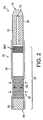
紙巻きタバコ10の別の実施態様を図2に示す。フィルターセクション20は、図1に示したフィルターセクション20と実質的に同じである。貫通孔70がタバコロッド15の長手方向軸に沿って延びている。貫通孔70は、燃えさし75から下流に高FEろ過材30の領域へと煙を移動させるための経路を提供している。貫通孔70の直径は、1から3mmである。実質的に互いに平行な複数の貫通孔を設けてもよい。貫通孔70は、フィルターセクション20へ熱が移動しやすくするものである。 Another embodiment of the
図1を参照して上述したように押出しまたは圧縮されたタバコと炭素の混合物からタバコロッド15を形成することで、貫通孔70の形成を容易にする。というのはこの混合材料は、貫通孔の外形および形状の維持に役立つからである。タバコを切断するためにグアールゴムまたは接着材料などの結合剤を加えて貫通孔の形状を維持しやすくするために使用することができる。 Forming the
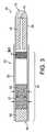
図2に示したものと類似しているが、フィルターセクション20が変更された紙巻きタバコ10を図3に示す。図2に示した隙間65などの隙間は、チッピング紙25に設けられていない。空気は、天然の多孔性であるチッピング紙25およびプラグラッパー27を透過する。同様に煙のいくつかの成分がフィルターセクション20から透過して出ることができる。 A
図1に示したものと類似している別の構成のフィルターセクション20を有する紙巻きタバコ10を図4に示す。この実施態様では吸着性材50が冷却チェンバー40に含まれており、これは冷却チェンバーキャビティーを満たすまたは実質的に満たす粒状のものである。 A
図1に示す紙巻きタバコ10にユーザーが火を付けると、燃えさし75がタバコロッド15を囲むタバコロッド15とラッパー26が燃焼する箇所で形成される。煙流が形成され、ユーザーがフィルターセクションの吸い口端55を介して吸引すると圧力差が生じてフィルターセクション20の方へと移動する。 When the user ignites the
煙流は、種々の構成成分から形成され、それぞれが蒸気相および/または粒状相に存在する。各相に存在する各煙成分の量は、煙の温度に依存する。蒸気相に存在する粒状煙成分の割合は、温度の上昇と共に増加する。 The smoke stream is formed from various components, each present in the vapor phase and / or the particulate phase. The amount of each smoke component present in each phase depends on the temperature of the smoke. The proportion of the particulate smoke component present in the vapor phase increases with increasing temperature.
煙がタバコロッド15を通って下流にフィルターセクション20の方に移動すると、煙が燃えさし75から移動することになるので、煙の温度が下がる。この煙の温度の低下の度合いは、煙の下流の流れを変えることなどの種々の要因で減少される。この煙の流れは、短いスリムタバコロッドを使用する、または溝または貫通孔を介してタバコの流れ抵抗を小さくし、タバコロッドの周囲に低通気度ラッパーを使用することによって影響を受ける。さらに熱伝導性材料を使用したり、タバコロッドの熱質量を減少させることも重要な要因である。 As smoke moves downstream through the
煙が高FE材の領域30に到達すると、粒状相内で移動した構成成分の大半が煙流から除去される。粒状相中の構成成分は、蒸気相を移動する構成成分より高い沸点を有する。従って比較的少量の蒸気相が必然的に煙流から高FE材30によって除去されることになる。しかしながら、さらにその後煙がフィルターセクション20を介して吸引された際にこれらの構成成分の一部を高FEろ過材30から溶出させてもよい。 When the smoke reaches the high
煙流は、さらに成分を煙エアロゾルに加えることによって煙を希釈する希釈剤保持材35を通過する。上述したように希釈剤保持剤35は、高FE材の領域30内または冷却チェンバー40の内部に配置してもよい。 The smoke stream passes through a
冷却チェンバー40の内部で煙は冷えて温度が下がる。煙が冷めると、それまで蒸気相に含まれていた種々の構成成分が粒状相に凝縮する。 Inside the cooling
煙が冷える速度は、煙は周囲空気で換気されるので、チッピング紙26の隙間65などのすべての穿孔の配置およびチッピング紙25やプラグラッパー27の天然の通気度合いによって影響される。隙間65の長さは、1から30mmであってもよい。 The speed at which the smoke cools is affected by the placement of all perforations, such as the gap 65 in the tipping
当業者には当然のことながら、チッピング紙25およびプラグラッパー27の選択は、それが煙の冷却および蒸気相や粒状相にある構成成分の割合を良好に調整することになるので、重要である。 As will be appreciated by those skilled in the art, the choice of tipping
煙が低FE材45の領域に入ると、粒状相の構成成分は、除去される。低FE材45の領域で煙流から除去される粒状材の量は、領域45のろ過効率が領域30より小さいので、高FE材の領域30で除去される量より少ない。 As smoke enters the region of
活性炭または煙成分の当業界で知られている他の吸着剤などの吸着性材50を低FE材45の領域内に配置してもよい。吸着性材50は、主に蒸気相中の煙成分を除去する。 An
最終的に煙流は、フィルターセクションの吸い口端55を介して吸引される。フィルターセクションの吸い口端55は、低FE材からなるプラグを含む。フィルターセクション吸い口端55は、特に炭素または他のこのような吸着剤が上流で使用されている場合に当業界で知られている種の風味剤を含浸させてもよい。 Eventually, the smoke stream is drawn through the mouth end 55 of the filter section. The
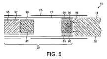
図5は別のフィルター構成を示している。フィルターセクション20は、タバコロッド15がフィルターセクション20に当接する箇所に位置する環状の高FE材80の領域を含む。環状フィルターセクション80の下流には中間のFE材85の領域が設けられている。高FE材80の領域および中間FE材85の領域は、熱伝導性材90で包んでもよく、さらにこれを断熱材95で包んでもよい。 FIG. 5 shows another filter configuration. The
この中間FE材85の下流には図1を参照して上述した構成と実質的に同じ構成のフィルターが設けられている。領域85のFEは、領域45のFEより高く、領域80のFEより低い。 A filter having substantially the same configuration as that described above with reference to FIG. 1 is provided downstream of the
使用する前は環状領域80の中央は、環状領域 80の長さに沿って延びる長手方向の貫通孔86を形成し、その幅は、約0.1から2mmである。使用中、特定の煙成分は、中央の貫通孔86内に堆積し、その結果煙成分に対して貫通孔86を少なくとも部分的に閉塞する。 Prior to use, the center of the
従って、最初の2、3回の吸引時、例えばフィルター領域80がまだ熱くなってなく、タバコロッド15が最も長いときのフィルター領域80の圧力降下は、フィルター領域80が熱くなり、タバコロッド15が少なくとも部分的に燃焼し、従って短くなったときの吸引時の圧力降下より小さくなる。最初の2、3回の吸引後にフィルター領域80を通過する煙は、従ってその後の吸引後に領域80を通過する煙の特定の煙成分を異なる割合で含むことになる。これは、初期の吸引時に領域80を介して吸引される煙は、中央の貫通孔86を通って移動することになり、実質的に領域80によってろ過されないからである。しかしながら、その後の吸引時からの煙は、環状領域80の外方の環に位置するろ過材を強制的に通過させられる。これとは形状または組成が異なる別のフィルター領域80も採用できることは当業者には明らかである。 Therefore, during the first and third aspirations, for example, when the
図5に示す紙巻きタバコ10において、低FEろ過材45の領域は、領域45とプラグラッパー27の間で高多孔度のプラグラッパー96で包んでもよく、このラッパーの多孔度はラッパー96の多孔度と類似するものであってもよい。フィルターセクションの吸い口端55を低FEろ過材45の領域を包むプラグラッパー96の多孔度より小さい多孔度のプラグラッパー97で包んでもよい。 In the
追加の変性をフィルターセクション20の種々の構成部材に組あわせてまたは別個に加えてもよい。例えば、冷却チェンバー40を囲むプラグラッパー27をグリセロールなどのエアロゾル形成材料で含浸させてもよく、またはエアロゾル形成材料を保持することができる材料からなる内層をさらに加えてもよい。 Additional modifications may be added to the various components of the
図6は、さらに別の実施態様による紙巻きタバコ10を示す。紙巻きタバコ10は、図1に示したものと類似しているが、環状のワッシャー100が高FE材30の領域の上流に位置している。ワッシャー100は、高FE材の領域30にぶつかるように煙流を集中させる、または案内し、熱損失を最小限に抑えるのを補助するために煙流の速度を維持する。高FE材30の領域およびワッシャー100を熱伝導性材90で包んでもよく、そしてこれを断熱材95で包んでもよい。 FIG. 6 shows a
ワッシャー100は、伝導性材料から形成してもよく、これによってフィルターセクション20への熱の移動を向上させる。冷却チェンバー40は、エアロゾルを形成しやすくするための圧力勾配を供するように成形されている。これとは別に冷却チェンバー40を少なくとも部分的に炭素などの吸着性材で充填してもよい。 The
図1から6に示すラッパー26は、その長さに沿って延びる追加の熱伝導手段を有してもよい。図7および8は、熱伝導ストリップ110を示している。熱伝導ストリップは、図1から6に示した燃えさし75から高FE材30、80の領域に熱を伝えることができ、煙がタバコロッド15を出て、フィルターセクション20に入る地点で煙の温度を上昇させる。熱伝導ストリップ110は、金属製であってもよく、または好適な伝導性材料を含んでもよい。 The
図7および8に示したストリップ110とは別にまたはこれに加えて、ラッパー26の内側に位置する裏紙またはラッパー26とのラミネートを含ませてもよく、これらは両方ともアルミ加工された紙の形状のものであってもよい。 Separately or in addition to the
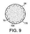
これとは別に図7および8に示す熱伝導ストリップ110は、タバコロッド15の長さに沿って熱伝導溝115が形成されるようにしてもよい。煙は、燃えさし75からこれらの溝115に沿って熱の損失を減少させるフィルターセクション20へ送られるようにしてもよい。ストリップは、紙、再生タバコまたは当業者に明らかなあらゆる好適な材料から形成してもよい。ストリップは、ラッパー26がタバコロッド15に巻かれる前または後にラッパー26に設けてもよい。図8は、タバコロッド15に巻かれる前にストリップ110が加えられたラッパー26を示している。ストリップ110は、タバコロッド15の長さの一部に沿ってまたはタバコロッド15の全長に沿って延びてもよい。これとは別に図9に示すように溝115は、ラッパー26とタバコロッド15の間に波形の内方ラッパー材120を設けて形成してもよい。 Alternatively, the
図7および9は、貫通孔70がない紙巻きタバコ10の端面を示しているが、このような貫通孔70を本発明の種々の実施態様にしたがって設けてもよい。 7 and 9 show the end face of the
紙巻きタバコ10の長手方向を通過する煙の温度分布および紙巻きタバコ10の構成部材の順番を変えるための変性を添付の特許請求の範囲で定義される本発明の範囲から逸脱することなく、行うことができる。 Modifications to alter the temperature distribution of the smoke passing through the length of the
当然のことながら上記の説明は紙巻きタバコを参照しているが、当業界で知られている他の喫煙品にも本発明の範囲内で同様に適用することができる。 Of course, the above description refers to cigarettes, but other smoking articles known in the art are equally applicable within the scope of the present invention.
実験データ
図1に示す紙巻きタバコ10と同様の紙巻きタバコの煙の温度分布を分析した。この紙巻きタバコは、フィルターセクションが希釈剤、吸着剤および換気隙間を含まない点で図1に示す紙巻きタバコ10と異なる。測定した煙成分は、粒状のニコチン、粒状の水、タール(NFDPM)、ベンゾ(a)ピレン(B(a)P)およびカテコールである。また表にはB(a)PとNFDPMとの比およびカテコールとNFDPMとの比さらには各紙巻きタバコからのパフまたは吸引回数を示した。本発明による紙巻きタバコを2本の対照紙巻きタバコと比較し、その結果を以下の表に示す。紙巻きタバコを2秒間で55立方センチメートル吸引し、吸引間は、30秒間間隔をおいて分析して調査した。Experimental Data The temperature distribution of cigarette smoke similar to the

本発明による例示紙巻きタバコと対照1および対照2は、同じタバコブレンド、タバコロッドおよび同じ長さのフィルターを含んでいた。対照1とラベルされた紙巻きタバコは、総粒状物(TPM)が本発明の紙巻きタバコと一致するように換気隙間を有する従来のセルロースアセテートフィルターを含んでいた。対照2とした紙巻きタバコは、本発明の紙巻きタバコと類似しているが、高FEろ過材30の領域を低効率のセルロースアセテートフィルターに代えた。本発明の紙巻きタバコにおいて、高FE材をガラス繊維から作製した。 An exemplary cigarette according to the present invention and
上記表に示した結果は、B(a)PおよびカテコールとNFDPMの比に関し、本発明による紙巻きタバコは対照紙巻きタバコのいずれよりも小さい。B(a)Pおよびカテコールは、比較的高い沸点を有し、従って高FEフィルター部分によってその特定の相で除去される。 The results shown in the table above relate to B (a) P and the ratio of catechol to NFDPM, with the cigarette according to the present invention being smaller than any of the control cigarettes. B (a) P and catechol have a relatively high boiling point and are therefore removed in that particular phase by the high FE filter portion.
本発明の実施態様は、従って煙成分の量をその相対沸点に基づいて調整するように構成することができる。例えば、本発明の実施態様の高FEフィルターの領域を比較的高い沸点、例えば特定の温度を超える沸点、例えば250℃、300℃、350℃、400℃、450℃または500℃の範囲の温度を超える沸点を有する煙成分だけを選択的に取り除くために使用することができる。このような構成成分は、高FEフィルター領域30、80、85を通過する際に粒状相に現れる。 Embodiments of the present invention can thus be configured to adjust the amount of smoke component based on its relative boiling point. For example, the region of the high FE filter of embodiments of the present invention may have a relatively high boiling point, for example, a boiling point above a certain temperature, such as a temperature in the range of 250 ° C, 300 ° C, 350 ° C, 400 ° C, 450 ° C or 500 ° C. Only smoke components having boiling points above can be used to selectively remove. Such constituents appear in the granular phase when passing through the high
冷却チェンバー 40内の煙を冷却することによって、本発明の特定の実施態様による吸着性材50を有する低FEフィルター材45は、比較的低沸点の煙成分、約300℃、250℃、200℃、150℃または100℃未満の沸点を有する構成成分を選択的に除去することができる。 By cooling the smoke in the cooling
様々な事項に対処し本技術を向上させるために、本開示の全体は説明によって種々の実施形態を示した。これら実施形態の中で、特許請求の範囲に規定された本発明が実施され、供給側製品から得られた知覚物質を用いて受容側製品へ感覚刺激性を付与する優れた方法が提供される。本開示の利点および特徴は実施形態の代表的実施例のものでしかなく、全てを包括するものでもこれらに限定されるものでもない。これらは単に理解を助け、特許請求の範囲に規定された特徴を教示するために提示される。当然のことながら、本開示の利点、実施形態、実施例、機能、特徴、構造、および/または他の態様は、特許請求の範囲によって規定された本開示に制限されるまたは特許請求の範囲の均等物に制限されると考えるのではなく、他の実施形態を利用しても改良しても本開示の概念の範囲から逸脱することはない。種々の実施形態が、本開示の要素、構成要素、特徴、部品、工程、手段その他の種々の組み合せを備えても、またはそれらから構成されても、または基本的にそれらから構成されてもよい。さらに本開示には、現在は特許請求されていないが将来特許請求される可能性がある他の発明も含まれる。
In order to address various issues and improve the present technology, the entire disclosure has shown various embodiments by way of explanation. Among these embodiments, the claimed invention is implemented to provide an excellent method of imparting sensory irritation to a recipient product using a sensory substance obtained from the supplier product. . The advantages and features of the present disclosure are only representative examples of embodiments and are not intended to be exhaustive or limited thereto. They are presented merely to aid understanding and to teach the features defined in the claims. It will be appreciated that the advantages, embodiments, examples, functions, features, structures, and / or other aspects of the disclosure are limited to or limited by the disclosure as defined by the claims. Rather than being considered limited to equivalents, other embodiments may be utilized or modified without departing from the scope of the disclosed concept. Various embodiments may comprise, consist of, or basically consist of various combinations, elements, components, features, parts, steps, means, etc. of the present disclosure. . The disclosure also includes other inventions that are not currently claimed but that may be claimed in the future.
Claims (18)
Translated fromJapanese煙流から粒状物を取り除くための第1ろ過材領域と、
前記第1ろ過材領域の下流にあり、前記第1ろ過材領域のろ過効率より低いろ過効率の第2ろ過材領域と、
前記第1ろ過材領域の下流で煙流を前記第2領域に入る前に冷却するための構造と、
ラッパーに巻かれた、一端に火を付けたときに燃えさしを形成するように構成された喫煙材ロッドとを含み、
前記ラッパーは、それに貼付された熱伝導ストリップを有し、燃えさしから第1ろ過材領域への熱移動を向上させ、そして、
前記喫煙材ロッドは、このロッド全体に亘って延びた少なくとも1つの溝を含み、燃えさしから第1ろ過材領域への熱移動を向上させ、さらに、
前記第1ろ過材領域、前記第2ろ過材領域、及び、前記構造は、煙成分の量をその相対沸点に基づいて調整するように構成されている喫煙品。A smoking product with a filter,
A first filter mediaarea for removing particulate matter from the smoke stream,
The first is downstream of the filter material region,and a second filtering materialarea of lower filtration efficiency than the filtration efficiency of the first filter medium area,
And structure for cooling before entering the smoke flow into the second region downstream of the first filter medium area,
A smoking material rod wound around a wrapper and configured to form a embers when lit at one end;
The wrapper has a heat conducting strip affixed thereto to improve heat transfer from the burner to the first filter media region; and
The smoking material rod includes at least one groove extending throughout the rod to improve heat transfer from the burner to the first filter media region;
The first filter medium region, the second filter medium region, and the structure are smoking articles configured toadjust the amount of smoke components based on their relative boiling points .
Applications Claiming Priority (3)
| Application Number | Priority Date | Filing Date | Title |
|---|---|---|---|
| GB1104788.3 | 2011-03-22 | ||
| GBGB1104788.3AGB201104788D0 (en) | 2011-03-22 | 2011-03-22 | Smoking article |
| PCT/EP2012/053802WO2012126721A1 (en) | 2011-03-22 | 2012-03-06 | Smoking article |
Publications (2)
| Publication Number | Publication Date |
|---|---|
| JP2014511675A JP2014511675A (en) | 2014-05-19 |
| JP5918348B2true JP5918348B2 (en) | 2016-05-18 |
Family
ID=44012947
Family Applications (1)
| Application Number | Title | Priority Date | Filing Date |
|---|---|---|---|
| JP2014500312AExpired - Fee RelatedJP5918348B2 (en) | 2011-03-22 | 2012-03-06 | Smoking goods |
Country Status (19)
| Country | Link |
|---|---|
| US (1) | US20140020698A1 (en) |
| EP (1) | EP2688430B1 (en) |
| JP (1) | JP5918348B2 (en) |
| KR (1) | KR20140020293A (en) |
| CN (1) | CN103501644B (en) |
| AR (1) | AR085529A1 (en) |
| AU (1) | AU2012230553B2 (en) |
| BR (1) | BR112013024191A2 (en) |
| CA (1) | CA2829718C (en) |
| CL (1) | CL2013002677A1 (en) |
| GB (1) | GB201104788D0 (en) |
| MX (1) | MX2013010876A (en) |
| MY (1) | MY164045A (en) |
| PH (1) | PH12013501913A1 (en) |
| RU (1) | RU2589437C2 (en) |
| TW (1) | TW201302109A (en) |
| UA (1) | UA110516C2 (en) |
| WO (1) | WO2012126721A1 (en) |
| ZA (1) | ZA201307033B (en) |
Families Citing this family (33)
| Publication number | Priority date | Publication date | Assignee | Title |
|---|---|---|---|---|
| GB201207211D0 (en)* | 2012-04-25 | 2012-06-06 | British American Tobacco Co | Smoking articles |
| CN103355742B (en)* | 2013-08-02 | 2015-06-17 | 云南烟草科学研究院 | Cigarette capable of greatly reducing harmful components in smoke and preparation method for cigarette |
| WO2015177907A1 (en)* | 2014-05-22 | 2015-11-26 | 日本たばこ産業株式会社 | Cigarette |
| EP3185705B1 (en)* | 2014-08-27 | 2019-10-23 | Philip Morris Products S.A. | Method for applying heat conducting patches to a material web |
| EP4628127A2 (en)* | 2015-04-06 | 2025-10-08 | Japan Tobacco Inc. | Flavor inhaler |
| GB201608928D0 (en)* | 2016-05-20 | 2016-07-06 | British American Tobacco Co | Article for use in apparatus for heating smokable material |
| DE102016121175A1 (en)* | 2016-11-07 | 2018-05-09 | Hauni Maschinenbau Gmbh | Rod-shaped smoking article and device for its production |
| RU2750465C2 (en) | 2016-12-16 | 2021-06-28 | Кей Ти Энд Джи Корпорейшн | Aerosol-generating apparatus |
| RU2737855C1 (en) | 2017-03-30 | 2020-12-03 | Кей Ти Энд Джи Корпорейшн | Aerosol generation device and holder to accommodate device thereof |
| GB201705152D0 (en) | 2017-03-30 | 2017-05-17 | British American Tobacco Investments Ltd | An article for use with an apparatus for heating an aerosol generating agent |
| US11622582B2 (en) | 2017-04-11 | 2023-04-11 | Kt&G Corporation | Aerosol generating device and method for providing adaptive feedback through puff recognition |
| US12102131B2 (en) | 2017-04-11 | 2024-10-01 | Kt&G Corporation | Aerosol generating device and method for providing adaptive feedback through puff recognition |
| CN115708600A (en) | 2017-04-11 | 2023-02-24 | 韩国烟草人参公社 | Aerosol generating device |
| JP6930687B2 (en) | 2017-04-11 | 2021-09-01 | ケーティー・アンド・ジー・コーポレーション | Aerosol generator |
| JP7180947B2 (en) | 2017-04-11 | 2022-11-30 | ケーティー アンド ジー コーポレイション | AEROSOL GENERATING DEVICES AND METHODS OF PROVIDING SMOKING RESTRICTION FEATURES IN AEROSOL GENERATING DEVICES |
| CN115024512B (en) | 2017-04-11 | 2025-09-19 | 韩国烟草人参公社 | Aerosol generating device |
| US11432593B2 (en) | 2017-04-11 | 2022-09-06 | Kt&G Corporation | Device for cleaning smoking member, and smoking member system |
| KR102035313B1 (en) | 2017-05-26 | 2019-10-22 | 주식회사 케이티앤지 | Heater assembly and aerosol generating apparatus having the same |
| CN116172276A (en) | 2017-08-09 | 2023-05-30 | 韩国烟草人参公社 | Aerosol generating device and aerosol generating device control method |
| WO2019031871A1 (en) | 2017-08-09 | 2019-02-14 | 주식회사 케이티앤지 | Electronic cigarette control method and device |
| JP6959429B2 (en) | 2017-09-06 | 2021-11-02 | ケーティー・アンド・ジー・コーポレーション | Aerosol generator |
| CN109965343A (en)* | 2017-12-27 | 2019-07-05 | 上海新型烟草制品研究院有限公司 | A kind of cigarette |
| WO2019177185A1 (en)* | 2018-03-12 | 2019-09-19 | 지씨인터내셔널 주식회사 | Cooling filter for heated tobacco product, and tobacco stick including same |
| KR102329088B1 (en)* | 2018-05-17 | 2021-11-18 | 주식회사 케이티앤지 | Article and apparatus for for generating generating aerosols |
| EA202092775A1 (en) | 2018-05-21 | 2021-03-15 | ДжейТи ИНТЕРНЭШНЛ СА | AEROSOL-GENERATING PRODUCT, METHOD FOR MANUFACTURING AEROSOL-GENERATING PRODUCT, AND AEROSOL-GENERATING SYSTEM |
| ES2913938T3 (en) | 2018-05-21 | 2022-06-06 | Jt Int Sa | Aerosol-generating articles and methods for manufacturing the same |
| GB201810738D0 (en)* | 2018-06-29 | 2018-08-15 | Nicoventures Trading Ltd | An aerosol generating component for a tobacco heating device and mouthpiece therefor |
| US10897925B2 (en) | 2018-07-27 | 2021-01-26 | Joseph Pandolfino | Articles and formulations for smoking products and vaporizers |
| US20200035118A1 (en) | 2018-07-27 | 2020-01-30 | Joseph Pandolfino | Methods and products to facilitate smokers switching to a tobacco heating product or e-cigarettes |
| CN109105951A (en)* | 2018-08-08 | 2019-01-01 | 郭凌凌 | A kind of cigarette reducing flue-gas temperature and its manufacturing method |
| CN108926030A (en)* | 2018-08-09 | 2018-12-04 | 四川三联新材料有限公司 | A kind of tobacco style leaf composition for multiple heating mode cigarette, multiple heating mode cigarette and preparation method thereof |
| EP3937681A4 (en)* | 2019-03-11 | 2023-03-22 | Selby, Ryan Daniel | IMPROVED SMOKING ARTICLE |
| GB202110881D0 (en)* | 2021-07-28 | 2021-09-08 | Nicoventures Trading Ltd | An article for use with a non-combustible aerosol provision device |
Family Cites Families (27)
| Publication number | Priority date | Publication date | Assignee | Title |
|---|---|---|---|---|
| US2667170A (en)* | 1950-04-01 | 1954-01-26 | Herbert A Lebert | Crimped wrapper for cigarettes |
| GB1086443A (en)* | 1966-05-03 | 1967-10-11 | James Alexander Everet Bell | Cigarette |
| DE2057282C3 (en)* | 1970-11-21 | 1979-03-29 | K H Steigerwald | Cigarette with secondary air duct |
| GB8429104D0 (en)* | 1984-11-17 | 1984-12-27 | British American Tobacco Co | Tobacco smoke filters |
| GB8713904D0 (en)* | 1987-06-15 | 1987-07-22 | Tabac Fab Reunies Sa | Filter for smoking articles |
| US5038803A (en)* | 1988-02-04 | 1991-08-13 | Hercules Incorporated | Method and device for control of by-products from cigarette smoke |
| US4913169A (en)* | 1989-03-17 | 1990-04-03 | Brown & Williamson Tobacco Corporation | Smoking article |
| GB9102658D0 (en)* | 1991-02-07 | 1991-03-27 | British American Tobacco Co | Improvements relating to smoking articles |
| US5016656A (en)* | 1990-02-20 | 1991-05-21 | Brown & Williamson Tobacco Corporation | Cigarette and method of making same |
| GB9023368D0 (en)* | 1990-10-26 | 1990-12-05 | Rothmans International Ltd | Smoking article |
| JPH0523158A (en)* | 1991-07-17 | 1993-02-02 | Daicel Chem Ind Ltd | Cigarette filter |
| IT1253273B (en)* | 1991-10-10 | 1995-07-14 | Gd Spa | SMOKING ARTICLE, IN PARTICULAR VENTILATED CIGARETTE, AND METHOD FOR ITS REALIZATION |
| IL104930A (en)* | 1992-03-25 | 1995-12-31 | Reynolds Tobacco Co R | Components for smoking articles and their manufacture |
| WO1998016125A1 (en)* | 1996-10-15 | 1998-04-23 | Rothmans, Benson & Hedges, Inc. | Cigarette sidestream smoke and free-burn rate control device |
| US20040154629A1 (en)* | 1998-01-28 | 2004-08-12 | Sampson John Roger | Smoking articles |
| US6129087A (en)* | 1998-03-25 | 2000-10-10 | Brown & Williamson Tobacco Corporation | Reduced ignition propensity smoking articles |
| MXPA03002306A (en)* | 2000-09-18 | 2003-10-15 | Rothmans Benson & Hedges | Low sidestream smoke cigarette with non-combustible treatment material. |
| US6863074B2 (en)* | 2002-08-30 | 2005-03-08 | Philip Morris Usa Inc. | Cigarette filters comprising unfunctionalized porous polyaromatic resins for removing gas phase constituents from mainstream tobacco smoke |
| US7856990B2 (en)* | 2003-09-30 | 2010-12-28 | R. J. Reynolds Tobacco Company | Filtered cigarette incorporating an adsorbent material |
| JP4959342B2 (en)* | 2004-12-27 | 2012-06-20 | 株式会社ダイセル | Tobacco filter material and tobacco filter |
| US7647932B2 (en)* | 2005-08-01 | 2010-01-19 | R.J. Reynolds Tobacco Company | Smoking article |
| US20070169786A1 (en)* | 2005-12-30 | 2007-07-26 | Philip Morris Usa Inc. | Corrugated catalytic cigarette paper and cigarettes comprising the same |
| MY177466A (en)* | 2006-03-28 | 2020-09-16 | Philip Morris Products Sa | Smoking article with a restrictor |
| US7726320B2 (en)* | 2006-10-18 | 2010-06-01 | R. J. Reynolds Tobacco Company | Tobacco-containing smoking article |
| US8235056B2 (en)* | 2006-12-29 | 2012-08-07 | Philip Morris Usa Inc. | Smoking article with concentric hollow core in tobacco rod and capsule containing flavorant and aerosol forming agents in the filter system |
| EP2025251A1 (en)* | 2007-08-17 | 2009-02-18 | Philip Morris Products S.A. | Multi-component filter for a smoking article |
| GB0818810D0 (en)* | 2008-10-14 | 2008-11-19 | British American Tobacco Co | Smoking article |
- 2011
- 2011-03-22GBGBGB1104788.3Apatent/GB201104788D0/ennot_activeCeased
- 2012
- 2012-03-06MYMYPI2013701656Apatent/MY164045A/enunknown
- 2012-03-06JPJP2014500312Apatent/JP5918348B2/ennot_activeExpired - Fee Related
- 2012-03-06CACA2829718Apatent/CA2829718C/ennot_activeExpired - Fee Related
- 2012-03-06EPEP12707583.6Apatent/EP2688430B1/ennot_activeNot-in-force
- 2012-03-06AUAU2012230553Apatent/AU2012230553B2/ennot_activeCeased
- 2012-03-06KRKR1020137027821Apatent/KR20140020293A/ennot_activeWithdrawn
- 2012-03-06CNCN201280014491.4Apatent/CN103501644B/ennot_activeExpired - Fee Related
- 2012-03-06MXMX2013010876Apatent/MX2013010876A/enunknown
- 2012-03-06USUS14/006,573patent/US20140020698A1/ennot_activeAbandoned
- 2012-03-06RURU2013146813/12Apatent/RU2589437C2/ennot_activeIP Right Cessation
- 2012-03-06PHPH1/2013/501913Apatent/PH12013501913A1/enunknown
- 2012-03-06BRBR112013024191Apatent/BR112013024191A2/ennot_activeIP Right Cessation
- 2012-03-06WOPCT/EP2012/053802patent/WO2012126721A1/enactiveApplication Filing
- 2012-03-21TWTW101109590Apatent/TW201302109A/enunknown
- 2012-03-22ARARP120100955Apatent/AR085529A1/ennot_activeApplication Discontinuation
- 2012-06-03UAUAA201312158Apatent/UA110516C2/enunknown
- 2013
- 2013-09-16CLCL2013002677Apatent/CL2013002677A1/enunknown
- 2013-09-18ZAZA2013/07033Apatent/ZA201307033B/enunknown
Also Published As
| Publication number | Publication date |
|---|---|
| CN103501644B (en) | 2016-12-07 |
| KR20140020293A (en) | 2014-02-18 |
| AR085529A1 (en) | 2013-10-09 |
| CN103501644A (en) | 2014-01-08 |
| BR112013024191A2 (en) | 2016-12-13 |
| CA2829718A1 (en) | 2012-09-27 |
| GB201104788D0 (en) | 2011-05-04 |
| WO2012126721A1 (en) | 2012-09-27 |
| CA2829718C (en) | 2015-11-24 |
| MX2013010876A (en) | 2013-10-17 |
| RU2589437C2 (en) | 2016-07-10 |
| ZA201307033B (en) | 2016-08-31 |
| RU2013146813A (en) | 2015-04-27 |
| EP2688430A1 (en) | 2014-01-29 |
| TW201302109A (en) | 2013-01-16 |
| AU2012230553B2 (en) | 2015-02-05 |
| AU2012230553A1 (en) | 2013-10-10 |
| JP2014511675A (en) | 2014-05-19 |
| PH12013501913A1 (en) | 2013-10-14 |
| UA110516C2 (en) | 2016-01-12 |
| CL2013002677A1 (en) | 2013-12-06 |
| MY164045A (en) | 2017-11-15 |
| US20140020698A1 (en) | 2014-01-23 |
| EP2688430B1 (en) | 2017-11-29 |
Similar Documents
| Publication | Publication Date | Title |
|---|---|---|
| JP5918348B2 (en) | Smoking goods | |
| JP3219297U (en) | Smoking filter | |
| JP6732724B2 (en) | Smoking articles containing menthol | |
| AU2008340634B2 (en) | Filter including randomly-oriented fibers for reduction of particle breakthrough | |
| US8240315B2 (en) | Smoking article with improved delivery profile | |
| JP5133258B2 (en) | Smoking articles having activated carbon and sodium bicarbonate treated fibers | |
| JP5786267B2 (en) | Smoking articles containing alkanoylated glycosides and methods of making | |
| US20070181140A1 (en) | Smoking article having flavorant materials retained in hollow heat conductive tubes | |
| JP3190703U (en) | Smoking filter | |
| JP6651495B2 (en) | Smoking article with concentric filter | |
| JP3191009U (en) | Smoking filter | |
| RU162983U1 (en) | FILTER FOR SMOKING | |
| HK1191519B (en) | Smoking article | |
| HK1191519A (en) | Smoking article | |
| RU2796054C2 (en) | Smoking product with cavity at end, brought to mouth, and ventilation | |
| CN114601195A (en) | a cigarette |
Legal Events
| Date | Code | Title | Description |
|---|---|---|---|
| A977 | Report on retrieval | Free format text:JAPANESE INTERMEDIATE CODE: A971007 Effective date:20150204 | |
| A131 | Notification of reasons for refusal | Free format text:JAPANESE INTERMEDIATE CODE: A131 Effective date:20150210 | |
| A521 | Request for written amendment filed | Free format text:JAPANESE INTERMEDIATE CODE: A523 Effective date:20150508 | |
| A131 | Notification of reasons for refusal | Free format text:JAPANESE INTERMEDIATE CODE: A131 Effective date:20151008 | |
| A521 | Request for written amendment filed | Free format text:JAPANESE INTERMEDIATE CODE: A523 Effective date:20160108 | |
| TRDD | Decision of grant or rejection written | ||
| A01 | Written decision to grant a patent or to grant a registration (utility model) | Free format text:JAPANESE INTERMEDIATE CODE: A01 Effective date:20160308 | |
| A61 | First payment of annual fees (during grant procedure) | Free format text:JAPANESE INTERMEDIATE CODE: A61 Effective date:20160407 | |
| R150 | Certificate of patent or registration of utility model | Ref document number:5918348 Country of ref document:JP Free format text:JAPANESE INTERMEDIATE CODE: R150 | |
| LAPS | Cancellation because of no payment of annual fees |