JP5914466B2 - Automatic surgical device - Google Patents
Automatic surgical deviceDownload PDFInfo
- Publication number
- JP5914466B2 JP5914466B2JP2013512178AJP2013512178AJP5914466B2JP 5914466 B2JP5914466 B2JP 5914466B2JP 2013512178 AJP2013512178 AJP 2013512178AJP 2013512178 AJP2013512178 AJP 2013512178AJP 5914466 B2JP5914466 B2JP 5914466B2
- Authority
- JP
- Japan
- Prior art keywords
- trocar
- central longitudinal
- proximal
- distal
- outer cannula
- Prior art date
- Legal status (The legal status is an assumption and is not a legal conclusion. Google has not performed a legal analysis and makes no representation as to the accuracy of the status listed.)
- Active
Links
- 230000002093peripheral effectEffects0.000claimsdescription32
- 239000012530fluidSubstances0.000claimsdescription29
- 239000011324beadSubstances0.000claimsdescription16
- 238000004891communicationMethods0.000claimsdescription11
- 238000001356surgical procedureMethods0.000claimsdescription11
- 239000000463materialSubstances0.000claimsdescription5
- 230000001788irregularEffects0.000claimsdescription2
- 238000000034methodMethods0.000description21
- 239000007789gasSubstances0.000description17
- 125000006850spacer groupChemical group0.000description16
- 230000008901benefitEffects0.000description5
- 210000001015abdomenAnatomy0.000description4
- 210000000683abdominal cavityAnatomy0.000description4
- 230000003187abdominal effectEffects0.000description4
- 238000007789sealingMethods0.000description3
- 238000003466weldingMethods0.000description3
- 210000001124body fluidAnatomy0.000description2
- 239000010839body fluidSubstances0.000description2
- 238000004140cleaningMethods0.000description2
- 238000010586diagramMethods0.000description2
- 239000003814drugSubstances0.000description2
- 229940079593drugDrugs0.000description2
- 238000012986modificationMethods0.000description2
- 230000004048modificationEffects0.000description2
- 238000012800visualizationMethods0.000description2
- 208000032544CicatrixDiseases0.000description1
- 230000003213activating effectEffects0.000description1
- 239000000853adhesiveSubstances0.000description1
- 230000001070adhesive effectEffects0.000description1
- 238000013459approachMethods0.000description1
- 239000012636effectorSubstances0.000description1
- 238000001914filtrationMethods0.000description1
- 208000014674injuryDiseases0.000description1
- 238000002357laparoscopic surgeryMethods0.000description1
- 238000012978minimally invasive surgical procedureMethods0.000description1
- 210000000056organAnatomy0.000description1
- 239000002861polymer materialSubstances0.000description1
- 238000011084recoveryMethods0.000description1
- 230000000717retained effectEffects0.000description1
- 231100000241scarToxicity0.000description1
- 230000037387scarsEffects0.000description1
- 229920005573silicon-containing polymerPolymers0.000description1
- 239000000126substanceSubstances0.000description1
- 230000008733traumaEffects0.000description1
- 238000005406washingMethods0.000description1
Images


Classifications
- A—HUMAN NECESSITIES
- A61—MEDICAL OR VETERINARY SCIENCE; HYGIENE
- A61B—DIAGNOSIS; SURGERY; IDENTIFICATION
- A61B17/00—Surgical instruments, devices or methods
- A61B17/34—Trocars; Puncturing needles
- A61B17/3417—Details of tips or shafts, e.g. grooves, expandable, bendable; Multiple coaxial sliding cannulas, e.g. for dilating
- A61B17/3421—Cannulas
- A—HUMAN NECESSITIES
- A61—MEDICAL OR VETERINARY SCIENCE; HYGIENE
- A61B—DIAGNOSIS; SURGERY; IDENTIFICATION
- A61B34/00—Computer-aided surgery; Manipulators or robots specially adapted for use in surgery
- A61B34/30—Surgical robots
- A—HUMAN NECESSITIES
- A61—MEDICAL OR VETERINARY SCIENCE; HYGIENE
- A61B—DIAGNOSIS; SURGERY; IDENTIFICATION
- A61B17/00—Surgical instruments, devices or methods
- A61B17/34—Trocars; Puncturing needles
- A61B17/3417—Details of tips or shafts, e.g. grooves, expandable, bendable; Multiple coaxial sliding cannulas, e.g. for dilating
- A61B17/3421—Cannulas
- A61B17/3423—Access ports, e.g. toroid shape introducers for instruments or hands
- A—HUMAN NECESSITIES
- A61—MEDICAL OR VETERINARY SCIENCE; HYGIENE
- A61B—DIAGNOSIS; SURGERY; IDENTIFICATION
- A61B17/00—Surgical instruments, devices or methods
- A61B17/34—Trocars; Puncturing needles
- A61B17/3462—Trocars; Puncturing needles with means for changing the diameter or the orientation of the entrance port of the cannula, e.g. for use with different-sized instruments, reduction ports, adapter seals
- A—HUMAN NECESSITIES
- A61—MEDICAL OR VETERINARY SCIENCE; HYGIENE
- A61B—DIAGNOSIS; SURGERY; IDENTIFICATION
- A61B17/00—Surgical instruments, devices or methods
- A61B17/34—Trocars; Puncturing needles
- A61B17/3474—Insufflating needles, e.g. Veress needles
- A—HUMAN NECESSITIES
- A61—MEDICAL OR VETERINARY SCIENCE; HYGIENE
- A61B—DIAGNOSIS; SURGERY; IDENTIFICATION
- A61B17/00—Surgical instruments, devices or methods
- A61B2017/00535—Surgical instruments, devices or methods pneumatically or hydraulically operated
- A61B2017/00544—Surgical instruments, devices or methods pneumatically or hydraulically operated pneumatically
- A—HUMAN NECESSITIES
- A61—MEDICAL OR VETERINARY SCIENCE; HYGIENE
- A61B—DIAGNOSIS; SURGERY; IDENTIFICATION
- A61B17/00—Surgical instruments, devices or methods
- A61B17/34—Trocars; Puncturing needles
- A61B17/3417—Details of tips or shafts, e.g. grooves, expandable, bendable; Multiple coaxial sliding cannulas, e.g. for dilating
- A61B17/3421—Cannulas
- A61B2017/3445—Cannulas used as instrument channel for multiple instruments
- A—HUMAN NECESSITIES
- A61—MEDICAL OR VETERINARY SCIENCE; HYGIENE
- A61B—DIAGNOSIS; SURGERY; IDENTIFICATION
- A61B34/00—Computer-aided surgery; Manipulators or robots specially adapted for use in surgery
- A61B34/30—Surgical robots
- A61B2034/302—Surgical robots specifically adapted for manipulations within body cavities, e.g. within abdominal or thoracic cavities
- A—HUMAN NECESSITIES
- A61—MEDICAL OR VETERINARY SCIENCE; HYGIENE
- A61B—DIAGNOSIS; SURGERY; IDENTIFICATION
- A61B90/00—Instruments, implements or accessories specially adapted for surgery or diagnosis and not covered by any of the groups A61B1/00 - A61B50/00, e.g. for luxation treatment or for protecting wound edges
- A61B90/06—Measuring instruments not otherwise provided for
- A61B2090/064—Measuring instruments not otherwise provided for for measuring force, pressure or mechanical tension
Landscapes
- Health & Medical Sciences (AREA)
- Life Sciences & Earth Sciences (AREA)
- Surgery (AREA)
- Engineering & Computer Science (AREA)
- Medical Informatics (AREA)
- Nuclear Medicine, Radiotherapy & Molecular Imaging (AREA)
- Biomedical Technology (AREA)
- Heart & Thoracic Surgery (AREA)
- Molecular Biology (AREA)
- Animal Behavior & Ethology (AREA)
- General Health & Medical Sciences (AREA)
- Public Health (AREA)
- Veterinary Medicine (AREA)
- Pathology (AREA)
- Robotics (AREA)
- Surgical Instruments (AREA)
Description
Translated fromJapanese関連出願の相互参照
本特許出願は、2010年5月24日に出願された米国仮特許出願第61/347,714号明細書に関連し、かつそれに対する利益または優先権を主張する。本特許出願は、また、2009年10月10日に出願された米国特許出願第12/577,179号明細書、2009年10月11日に出願された米国特許出願第12/577,189号明細書、2009年10月9日に出願された米国特許出願第12/587、584号明細書、2009年10月11日に出願された米国仮特許出願第61/250,521号明細書、2007年4月13日に出願された米国特許出願第11/786,832号明細書、2006年10月6日に出願された米国特許出願第11/544,856号明細書および2008年10月10日に出願された米国特許出願第61/104,501号明細書にも関連する。上述した特許出願の各々は、全体として参照により本明細書に組み込まれる。CROSS REFERENCE TO RELATED APPLICATIONS This patent application is related to and claims benefit or priority to US Provisional Patent Application No. 61 / 347,714, filed May 24, 2010. This patent application also includes US patent application Ser. No. 12 / 577,179, filed Oct. 10, 2009, and US Patent Application No. 12 / 577,189, filed Oct. 11, 2009. US patent application Ser. No. 12 / 587,584, filed Oct. 9, 2009, US provisional patent application No. 61 / 250,521, filed Oct. 11, 2009, U.S. Patent Application No. 11 / 786,832 filed on April 13, 2007, U.S. Patent Application No. 11 / 544,856 filed on October 6, 2006, and Oct. 2008 Also relevant is US patent application Ser. No. 61 / 104,501, filed on the 10th. Each of the aforementioned patent applications is incorporated herein by reference in its entirety.
本願は、外科用アクセス装置(または外科用アクセス・ポート)および関連方法に関連する。より詳細には、本発明は、オペレータによって制御されるロボット手段等、手術を行う自動化手段を使用する単孔式腹腔鏡下手術(single-incision laparoscopic surgical)(「SILS」)手技で使用するのに有利に適合されている装置に関する。本願は、また、こうした外科用アクセス装置を用いるキットおよび方法にも関する。 The present application relates to surgical access devices (or surgical access ports) and related methods. More particularly, the present invention is for use in single-incision laparoscopic surgical ("SILS") procedures that use automated means for performing surgery, such as robotic means controlled by an operator. To an apparatus that is advantageously adapted to. The present application also relates to kits and methods using such surgical access devices.
患者の外傷を低減するとともに、はん痕の量を低減するために、単孔で低侵襲手術手技を行う技法がますます開発されている。複数の従来の外科手術用器具を同時に単孔を通して挿入することは、相互に干渉し、かつ利用可能な空間が不足するため、困難であることが多い。したがって、こうした手法を容易にする装置、システムおよび手順を開発することが必要となった。上述したことと並行して、ロボット工学に頼る遠隔手術の分野では多くの進歩が遂げられてきた。本発明は、SILSの分野において、特に後述するようにロボット技術に関連する、改善を提供する。 In order to reduce patient trauma and reduce the amount of scars, techniques for performing single-hole, minimally invasive surgical procedures are increasingly being developed. Inserting multiple conventional surgical instruments simultaneously through a single hole is often difficult because they interfere with each other and lack available space. Therefore, it has become necessary to develop devices, systems and procedures that facilitate such techniques. In parallel with the above, much progress has been made in the field of telesurgery that relies on robotics. The present invention provides improvements in the field of SILS, particularly related to robotics, as described below.
本発明の利点は、以下の説明に示されており、かつ、そこから明らかとなろう。本発明のさらなる利点は、明細書およびその特許請求の範囲において、かつ添付図面から特に指摘されている方法およびシステムによって具現化され、かつ達成される。 The advantages of the present invention are set forth in, and will be apparent from, the following description. Additional advantages of the invention will be realized and attained by the method and system particularly pointed out in the written description and claims hereof and from the appended drawings.
これらの利点および他の利点を達成するために、かつ本明細書において具現化されるように、本発明の目的に従って、本発明は、手術手技で使用されるシステムを含む。第1態様では、本システムは、実質的に管状の内壁と実質的に管状の外壁とを有するトロカールを含み、トロカールは、近位端および遠位端を有し、内壁は、トロカールを通るアクセスを提供するように中心長手方向内腔を画定している。トロカールは、入れ子配置で、外側カニューレと、外側カニューレ内に配置された内側カニューレであって、トロカールを通るアクセスを提供するように、少なくとも部分的に中心長手方向内腔を画定する内側カニューレと、外側カニューレ内に配置された管中心構成要素と、外側カニューレ内に配置された環状噴射口アセンブリとを含む。管中心構成要素および環状噴射口アセンブリは、嵌合して、トロカールによって画定される中心長手方向軸を中心に環状に配置された複数のノズル通路を画定する。管中心構成要素および環状噴射口アセンブリは、加圧ガスを受け取ることができるプレナムを画定するように適合され、かつ構成され、プレナムは、ノズル通路と流体連通している。そして、ノズル通路は、トロカールの遠位端に向かってトロカールの長手方向軸に対して実質的に平行に高速噴射を噴出するように適合され、かつ構成されている。 In order to achieve these and other advantages and as embodied herein, in accordance with the purpose of the present invention, the present invention includes a system used in surgical procedures. In a first aspect, the system includes a trocar having a substantially tubular inner wall and a substantially tubular outer wall, the trocar having a proximal end and a distal end, the inner wall being accessible through the trocar. A central longitudinal lumen is defined to provide The trocar is a nested arrangement, an outer cannula and an inner cannula disposed within the outer cannula, the inner cannula defining at least partially a central longitudinal lumen so as to provide access through the trocar; A tube center component disposed within the outer cannula and an annular spout assembly disposed within the outer cannula. The tube center component and the annular nozzle assembly are mated to define a plurality of nozzle passages arranged annularly about a central longitudinal axis defined by the trocar. The tube center component and the annular nozzle assembly are adapted and configured to define a plenum capable of receiving pressurized gas, the plenum being in fluid communication with the nozzle passage. The nozzle passage is then adapted and configured to eject a high velocity jet substantially parallel to the longitudinal axis of the trocar toward the distal end of the trocar.
さらなる実施態様では、本システムは、トロカールの中心長手方向内腔内に配置された器具ガイドを含む。器具ガイドは、近位端、遠位端、および近位端から遠位端まで器具ガイドを通して画定された複数の溝を有し、各溝は、外科手術用器具を受け取るように適合されかつ構成されている。 In a further embodiment, the system includes an instrument guide disposed within the central longitudinal lumen of the trocar. The instrument guide has a proximal end, a distal end, and a plurality of grooves defined through the instrument guide from the proximal end to the distal end, each groove adapted and configured to receive a surgical instrument. Has been.
一実施形態によれば、器具ガイドは、半径方向に拡大したフレア状近位領域と細長い遠位領域とを含み、各溝は、器具ガイドがトロカールに挿入されると、トロカールの中心長手方向軸から角度が付けられる少なくとも1つの細長い湾曲壁によって画定されている。好ましくは、器具ガイドの溝のうちの少なくとも1つは、器具ガイドの側部に沿って、その長さに沿って開放している。さらなる実施形態では、器具ガイドの溝のうちの少なくとも1つは、その長さに沿って略円形断面を有している。別の実施形態では、器具ガイドの溝のうちの少なくとも1つは、その長さに沿って略楕円形断面を有している。 According to one embodiment, the instrument guide includes a radially expanded flared proximal region and an elongated distal region, each groove being a central longitudinal axis of the trocar when the instrument guide is inserted into the trocar. Defined by at least one elongated curved wall angled from. Preferably, at least one of the grooves of the instrument guide is open along its length along the side of the instrument guide. In a further embodiment, at least one of the instrument guide grooves has a generally circular cross-section along its length. In another embodiment, at least one of the instrument guide grooves has a generally elliptical cross section along its length.
さらなる実施態様によれば、トロカールは、外側カニューレの外側部分に取り付けられた流体マニホルドをさらに有することができ、マニホルドは、その中を通る複数の流体通路を画定している。流体マニホルドの通路のうちの1つは、好ましくは、ノズル通路と流体連通するプレナムと直接流体連通している。さらなる実施形態では、トロカールは、ノズル通路に対して遠位に位置する外側カニューレ内に配置された吸引拡張部をさらに有することができる。 According to a further embodiment, the trocar can further include a fluid manifold attached to the outer portion of the outer cannula, the manifold defining a plurality of fluid passages therethrough. One of the fluid manifold passages is preferably in direct fluid communication with a plenum in fluid communication with the nozzle passage. In a further embodiment, the trocar can further have a suction extension disposed in the outer cannula located distal to the nozzle passage.
さらなる実施態様によれば、トロカールは、ノズル通路に対して近位に位置する外側カニューレ内の吸音バッフルをさらに有することができ、吸音バッフルは柔軟な材料から作製されている。吸音バッフルは、近位周縁ビードと、遠位周縁ビードと、不規則な表面によって画定された、近位周縁ビードおよび遠位周縁ビードによって境界が画された中空体であって、少なくとも1つの外科手術用器具が内部を通過するのを可能にするように、偏向するように適合されかつ構成された中空体とを含む。中空体は、首領域によって遠位周縁部分に接続された近位周縁部分を含むことができる。首領域は、ノズル通路を通る流れから発する音を調節する起伏を内部に含むことができる。近位周縁ビードおよび遠位周縁ビードを、トロカールの隣接する部分の間に捕捉しかつ適所に保持することができる。 According to a further embodiment, the trocar can further have a sound absorbing baffle in the outer cannula located proximal to the nozzle passage, the sound absorbing baffle being made from a flexible material. The sound absorbing baffle is a hollow body bounded by a proximal peripheral bead and a distal peripheral bead defined by a proximal peripheral bead, a distal peripheral bead, and an irregular surface, and comprising at least one surgical A hollow body adapted and configured to deflect so as to allow the surgical instrument to pass therethrough. The hollow body can include a proximal peripheral portion connected to the distal peripheral portion by a neck region. The neck region can include undulations that adjust the sound emanating from the flow through the nozzle passage. A proximal peripheral bead and a distal peripheral bead can be captured and held in place between adjacent portions of the trocar.
さらなる実施態様によれば、トロカールは、それ自体を通して、外側カニューレの外面から内側カニューレを通って中心長手方向内腔内に側部ポートを画定することができる。側部ポートは、中心長手方向軸に対して角度が付けられている。側部ポートは、器具を、内部を通してかつ中心長手方向内腔内に受け取るように適合され、かつ構成されている。 According to a further embodiment, the trocar can define a side port through itself from the outer surface of the outer cannula, through the inner cannula, and into the central longitudinal lumen. The side port is angled with respect to the central longitudinal axis. The side port is adapted and configured to receive the instrument through the interior and into the central longitudinal lumen.
本発明は、また、ロボット手術システムも提供する。本システムは、第1実施態様では、複数の遠隔制御可能なアームを有する遠隔制御手術システムを備え、各アームは、手術手技の一部を行うのに適しており、各アームは、ユーザ・コンソールから遠隔に制御可能である。本システムは、上述したトロカールと器具ガイドとをさらに備え、器具ガイドの各溝は、遠隔制御手術システムの遠隔制御可能なアームのうちの1つを受け取るように適合されかつ構成されている。 The present invention also provides a robotic surgical system. The system, in the first embodiment, comprises a remotely controlled surgical system having a plurality of remotely controllable arms, each arm suitable for performing a part of a surgical procedure, each arm being a user console Can be controlled remotely. The system further comprises a trocar and an instrument guide as described above, wherein each groove of the instrument guide is adapted and configured to receive one of the remotely controllable arms of the remotely controlled surgical system.
さらに本発明によれば、患者に対して手術を行う方法が提供される。本方法は、複数の遠隔制御可能なアームを有する遠隔制御手術システムを提供するステップであって、各アームが、手術手技の一部を行うのに適しており、各アームが、ユーザ・コンソールから遠隔に制御可能である、ステップを含む。本方法は、患者の内部にアクセスするために患者の切開部を通して、上述したトロカールを配置するステップをさらに含む。本方法は、トロカールの中心長手方向内腔に上述した器具ガイドを配置するステップと、トロカールのプレナムを加圧することにより、トロカールにおける複数の噴射口を作動させるステップと、少なくとも1つの遠隔制御可能なアームを、器具ガイドのうちの少なくとも1つを通して患者内に配置するステップと、少なくとも1つの遠隔制御可能なアームを用いて手術手技を行うステップとをさらに含む。 Furthermore, according to the present invention, a method for performing surgery on a patient is provided. The method includes providing a remotely controlled surgical system having a plurality of remotely controllable arms, each arm suitable for performing a portion of a surgical procedure, wherein each arm is from a user console. Includes steps that are remotely controllable. The method further includes positioning the trocar described above through the patient's incision to access the interior of the patient. The method includes locating the instrument guide described above in the central longitudinal lumen of the trocar, activating a plurality of jets in the trocar by pressurizing the trocar plenum, and at least one remotely controllable. Positioning the arm in the patient through at least one of the instrument guides and performing a surgical procedure using the at least one remotely controllable arm.
さらなる実施態様によれば、本方法は、また、トロカールを通って中心長手方向内腔内に画定された側部ポートを介して器具を導入するステップであって、側部ポートが、中心長手方向軸に対して角度が付けられている、ステップも含むことができる。側部ポートを介して導入される器具を、患者内に薬品を送達する針、開創器、拡張器、把持器、吸引装置および洗浄装置からなる群から選択することができる。 According to a further embodiment, the method also includes introducing an instrument through the trocar through a side port defined in the central longitudinal lumen, wherein the side port is in the central longitudinal direction. A step that is angled relative to the axis can also be included. The instrument introduced through the side port can be selected from the group consisting of a needle, a retractor, a dilator, a grasper, a suction device, and a cleaning device that delivers a drug into the patient.
本発明は、好ましくは、上述したトロカールに関連して、自動/ロボット手術システムでまたは用手的手術技法に関連して使用される上述した器具ガイドをさらに提供する。 The present invention further provides an instrument guide as described above, preferably used in connection with the trocar described above, in an automated / robot surgical system or in connection with manual surgical techniques.
上述した概略的な説明および以下の詳細な説明は例示的なものであり、開示する実施形態のさらなる説明を提供するように意図されていることが理解されるべきである。本明細書に組み込まれ、かつその一部を構成する添付図面は、開示する実施形態の方法およびシステムを例示しかつそれらのさらなる理解のために含まれている。説明とともに、図面は、開示する実施形態の原理を説明する役割を果たす。 It should be understood that the foregoing general description and the following detailed description are exemplary and are intended to provide further explanation of the disclosed embodiments. The accompanying drawings, which are incorporated in and constitute a part of this specification, illustrate the methods and systems of the disclosed embodiments and are included for further understanding thereof. Together with the description, the drawings serve to explain the principles of the disclosed embodiments.
ここで、本発明の現時点で好ましい実施形態を詳細に参照し、その例を添付図面に示す。開示する実施形態の方法および対応するステップを、システムの詳細な説明に関連して説明する。本明細書に組み込まれ、かつその構成部分である添付図面は、本開示の方法およびシステムを例示しかつそれらのさらなる理解のために含まれている。説明とともに、図面は、開示する実施形態の原理を説明する役割を果たす。 Reference will now be made in detail to the presently preferred embodiments of the invention, examples of which are illustrated in the accompanying drawings. The method and corresponding steps of the disclosed embodiments are described in connection with a detailed description of the system. The accompanying drawings, which are incorporated in and constitute a part of this specification, illustrate the method and system of the present disclosure and are included for further understanding thereof. Together with the description, the drawings serve to explain the principles of the disclosed embodiments.
ロボット手術システムは、本技術分野において受け入れられ、特定の患者および外科医には好まれるようになってきた。こうしたシステムの1つは、Intuitive Surgical, Inc.(Sunnyvale、California、USA)のDaVinci手術システムとして一般に知られている。このシステムの態様を、特に、米国特許第7,695,481号明細書、同第7,316,681号明細書、同第7,453,227号明細書、同第7,666,191号明細書、同第7,507,199号明細書および同第7,689,320号明細書に見ることができる。上述した特許の各々は、その全体が参照により本明細書に組み込まれる。 Robotic surgical systems have become accepted in the art and have become preferred by certain patients and surgeons. One such system is commonly known as the DaVinci surgical system of Intuitive Surgical, Inc. (Sunnyvale, California, USA). Embodiments of this system are described in particular in US Pat. Nos. 7,695,481, 7,316,681, 7,453,227, and 7,666,191. Nos. 7,507,199 and 7,689,320. Each of the aforementioned patents is incorporated herein by reference in its entirety.
DaVinciシステムの主要な実施態様は、ユーザ・コンソールから遠隔に制御される複数のロボット・アームおよび器具の使用である。ロボット・アームの各々は、クランプ、鉗子、外科用メス等、エンドエフェクタとして種々の外科手術用器具を備えることができる。こうしたシステムの別の主要な実施態様は、手術が行われている患者の内部の領域を見るために(内視鏡を用いる等による)遠隔可視化が用いられるということである。DaVinciシステムの欠点は、患者内に挿入される器具の各々に対応するために複数の腹部開口部または腹部切開部が一般に使用されるということである。 The main implementation of the DaVinci system is the use of multiple robot arms and instruments that are remotely controlled from a user console. Each robotic arm can be equipped with various surgical instruments as end effectors, such as clamps, forceps, surgical scalpels, and the like. Another major embodiment of such a system is that remote visualization (such as by using an endoscope) is used to see the area inside the patient undergoing surgery. A drawback of the DaVinci system is that multiple abdominal openings or abdominal incisions are commonly used to accommodate each of the instruments inserted into the patient.
回復を早めるために、患者の体内では可能な限り少ない腹部開口部を用いることが通常望ましい。腹腔鏡下手術の場合、複数の器具に対応するために大きい開口部を有する単一のトロカールを用いることは特に困難である、なぜなら、本技術分野おいて一般に知られている機械的トロカール・シールは、トロカールを介して吹送ガスを喪失しないように、かつトロカールから体液が漏れないように、単一器具に対応しているときに最もよく機能するためである。特に、円形断面がない器具の使用、または単一トロカールを介した複数の器具の使用は、器具の周囲における機械的封止が不十分となるため好まれない。 It is usually desirable to use as few abdominal openings as possible in the patient's body to expedite recovery. In the case of laparoscopic surgery, it is particularly difficult to use a single trocar with a large opening to accommodate multiple instruments because mechanical trocar seals commonly known in the art Because it works best when dealing with a single instrument so as not to lose insufflation gas through the trocar and to prevent body fluids from leaking through the trocar. In particular, the use of instruments that do not have a circular cross-section, or the use of multiple instruments via a single trocar, is not preferred due to insufficient mechanical sealing around the instrument.
しかしながら、本出願人らは、手術室と通気された腹腔との間の差圧を維持するために通常の機械的シールを用いない一連のトロカールを開発した。概して、これらのトロカールは、ガスが腹部から漏れようとするのを妨げるために、代りに高速ガス流の運動量に依存する。こうしたトロカールの例を、本特許出願の第1頁において参照により組み込まれた特許出願とともに、同様に全体として参照により本明細書に組み込まれる、米国特許第7,182,752号明細書、同第7,285,112号明細書、同第7,338,473号明細書および同第7,413,559号明細書に開示されているものと同様に見ることができる。こうしたトロカールは、患者の通気された腹腔から吹送ガスまたは体液あるいは排出物が漏れないように機械的シールを用いない。結果として、複数の手技を行うために、断面の異なる複数の手術用器具を単独でまたは同時に使用することができる。 However, Applicants have developed a series of trocars that do not use conventional mechanical seals to maintain the differential pressure between the operating room and the ventilated abdominal cavity. In general, these trocars rely instead on the momentum of the high velocity gas flow to prevent gas from trying to escape from the abdomen. Examples of such trocars are described in US Pat. No. 7,182,752, which is hereby incorporated by reference in its entirety, together with patent applications incorporated by reference on page 1 of this patent application. Similar to those disclosed in US Pat. Nos. 7,285,112, 7,338,473, and 7,413,559. Such trocars do not use mechanical seals to prevent insufflation gases or body fluids or effluents from leaking from the patient's ventilated abdominal cavity. As a result, multiple surgical instruments having different cross-sections can be used alone or simultaneously to perform multiple procedures.
この利点に起因して、こうしたトロカールを上述したDaVinciシステム等のロボットシステムと協働して使用することにより、単一のトロカールを介して複数のロボット器具および可視化スコープを使用して、腹腔鏡下手技等の手術手技を行うことが可能である。こうした手技を容易にするために、本明細書では、複数のロボット手術器具を誘導するためにトロカールおよびさまざまな挿入物が提供される。 Due to this advantage, these trocars can be used in conjunction with a robotic system, such as the DaVinci system described above, using multiple robotic instruments and visualization scopes through a single trocar, laparoscopically It is possible to perform a surgical procedure such as a procedure. To facilitate such procedures, trocars and various inserts are provided herein to guide a plurality of robotic surgical instruments.
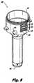
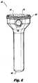
導入として、例示的なトロカールを図1〜図18に提示し図示する。本明細書において具現化されるように、かつ図1に示すように、トロカール100は、近位端102と、遠位端104と、近位端102から遠位端104までその内部を通る実質的に円柱状のボア106とを含む。ボア106は、好ましくは、図19〜図28に関して後に詳細に説明する器具挿入物および器具を受け取るように寸法が決められ、かつ適合されている。 As an introduction, an exemplary trocar is presented and illustrated in FIGS. As embodied herein and as shown in FIG. 1, the
図1にさらに示すように、トロカール100は、後にさらに詳細に説明する入れ子になった複数の構成要素を組み立てることによって作製される。図1に示すように、トロカール100は、入れ子配置で、外側カニューレ110、内側カニューレ120、キャップ・スペーサ・リング130、段付円錐形スペーサ140、上部キャップ150、吸音バッフル160、底部キャップ170、管中心構成要素180、環状噴射口アセンブリ190および吸引拡張部200を有している。カニューレ210は、外側カニューレ110の外側部分に取り付けられた流体マニホルド210をさらに有している。上述した構成要素の各々を、ここでさらに詳細に説明する。 As further shown in FIG. 1, the
図2〜図5に、外側カニューレ110のさまざまな図を示す。図示するように、外側カニューレ110は、近位端112、遠位端114を有し、その内部を通して長手方向ボア116を画定している。さらに図示するように、外側カニューレ110はまた、その内部を通して、かつトロカール100のボア106内に器具を受け取るように、内部に(内側カニューレ120のポート128と整列する)側部ポート118も画定している。こうした器具としては、たとえば、患者の腹腔内に、または患者の腹腔内の組織あるいは器官に局所的に、さまざまな薬品を送達する針等、開創器、拡張器、把持器および吸引・洗浄装置を挙げることができる。外側カニューレ110の外面は、その上に、流体マニホルド210を受け入れる取付固定具115を画定している。図示するように、流体マニホルド210は、マニホルド210の頂部のポート212で開始して、外側カニューレ110の側部を通って画定される溝穴113で終端する、3つの流路を内部に画定している。上述した流路の各々は、トロカール110の他の部分と協働して、流路またはプレナムを画定する。参照数字220、230および240によって注釈されている各プレナムは、後述するように、トロカール100の動作において異なる目的にかなう。マニホルド210は、好ましくは、流体プレナムが気密シールによって互いに流体分離されたままであることを確実にするように、外側カニューレ110に永久的に接合されている。外側カニューレは、さらに、内部に複数の検知ポート119を画定している。他のトロカール構成要素を組み立てられると、検知ポート119は、特に外側カニューレ110および内側カニューレ120によって画定される検知プレナム240と流体連通する。 2-5, various views of the
図6および図7に示すように、内側カニューレ120は、近位端122、遠位端124を有し、その内部を通して長手方向ボア126を画定している。ポート128はポート118と整列して、医療処置中に必要に応じて、針、開創器、洗浄・吸引器具等のさまざまな補助器具を導入することができる溝を画定する。内側カニューレ120は、その近位端122の周囲に、封止リング252(図1を参照)を受け入れるように適合され、かつ構成されている周縁溝125を画定している。組み立てられると、封止リング252は、外側カニューレ110と内側カニューレ120との間に挿入され、それにより、マニホルド210内の専用の通路242と協働して検知プレナム240を画定する。 As shown in FIGS. 6 and 7, the
内側カニューレ120は、その上部周縁部に沿って一連の弓形切欠き123をさらに画定している。内側カニューレ120の近位端122の周縁部は、吸引拡張部200の近位端202に画定された周縁溝203に位置し、かつ、それによって受け入れられる。組み立てられると、切欠き123は通路232と流体連通する流体ポートとして作用して、ガスおよび他の流体をトロカール100および/または患者の腹部から濾過および再循環アセンブリ(図示せず)内に排出する、後にさらに詳細に説明する排出または再循環プレナム230を画定する。
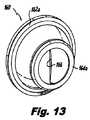
図12および図13に示すように、吸音バッフル160は、可撓性があり、器具をトロカール100のボア106を通して配置することによる等、変形した後に、元の形状に戻ることができる、生体許容性の弾性シリコーン系ポリマー材料等の柔軟な材料から作製されている。吸音バッフル160は、砂時計形断面を有しており(図1)、かつ近位周縁部162および遠位周縁部164を有しているように示されている。図示するように、近位周縁部162は、首領域165によって遠位周縁部164に接続されている。代替実施形態として、首領域165は、内部に起伏または折目(165aとして破線に示す)を含むことができる。こうした起伏は、使用時にトロカール100によって生成される騒音をさらに低減することができることが分かった。さらに、直線断面を有する通路166を図示しているが、米国特許出願第61/250,521号明細書(たとえば図54および図55ならびに関連する本文を参照)に詳細に記載されているように、正弦波形状等、断面に対していかなる所望の形状を使用することも可能である。吸音バッフルは、近位周縁ビード162aおよび遠位周縁ビード164aをさらに画定している。 As shown in FIGS. 12 and 13, the
吸音バッフル160は、キャップ・スペーサ・リング130、段状円錐形スペーサ140および底部キャップ170の結合されたサブアセンブリによって適所に保持される。特に、図8に示すように、キャップ・スペーサ・リング130は、上に外側周縁132および遠位係合面134を画定する略トロイド形本体を有している。図9に、さらに図示するように、段付円錐形スペーサ140は、その上に環状近位係合面142および環状遠位係合面144を画定している。図10に示すように、底部キャップ170は、近位環状係合面172、遠位環状係合面174および外側周囲面176を画定している。図1をさらに参照すると、バッフル160の近位部162の周縁は、キャップ・スペーサ・リング130の遠位係合面134と段付円錐形スペーサ140の近位係合面142との間の適所に保持される。
図示するように、バッフル160の周縁ビード162aは、キャップ・スペーサ・リングおよびスペーサ140によって画定されるチャンバ162b内の適所に保持される。同様に、バッフル160の遠位部164の周縁は、スペーサ140の遠位係合面144とエンド・キャップ170の近位係合面172との間の適所に保持される。図示するように、バッフル160の周縁ビード164aは、スペーサ140およびエンド・キャップ170によって画定されるチャンバ164b内の適所に保持される。エンド・キャップの環状係合面174は、管中心構成要素180(図14および図15)の近位係合面182および内周面185によって受け取られる。そして、スペーサ140は、周囲面152によって画定される上部キャップ150の開口部145内に位置する。上部キャップ150のねじ山154は、外側カニューレ110のねじ山111と嵌合する。組み立てられると、キャップ150を外側カニューレ110にねじ込むことにより、すべての入れ子になった構成要素(110、120、180、190、200)が互いに堅固に保持され、トロカール100の簡単な組立てを可能にする。別の方法として、キャップ150を、限定されないが、ラッチ、スナップ、摩擦嵌合、接着剤、たとえばスピン溶接を含む熱溶接あるいは摩擦溶接等の溶接を含む、種々の方法で外側カニューレ110に固定することができる。構成要素130、140、150、160、170は、図19〜図28に示すもののような器具ガイドを挿入するときに、望ましい場合は取り除くことができるサブアセンブリを形成する。タブ146(図9)は、サブアセンブリの取外しを容易にすることができる。サブアセンブリは、好ましくは、動作時にトロカール100によって発生する騒音を低減するのに非常に有効であるため、適所に残される。バッフル・サブアセンブリの構成要素は、好ましくは、溶接されるか、または他の方法で互いに接合され、バッフル160を適所に締め付ける。サブアセンブリは、好ましくは、トロカールに対して近位−遠位方向において望ましくない移動を防止するが、相対的な回転移動を可能にするように適所に嵌る。したがって、スナップイン接続が好ましい。さらに、バッフルの材料は、挿入されるときに器具ガイド(300、400)を把持して、それが外れるのを防止するのに概して好適であるため、バッフルを適所に残すことも好ましい。トロカール100に対するガイドの回転移動を可能にするが、トロカール100に対する近位−遠位方向に沿った望ましくない移動は可能にしないように、器具ガイドにスナップ嵌合を提供することも可能である。 As shown, the
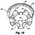
限定ではなくさらなる例示を目的として、管中心構成要素180および環状噴射口アセンブリ190は入れ子になって1つまたは複数の流体噴射口を形成する。特に、図14に示すように、中心構成要素180は、その外面に1つまたは複数の戻止め183を画定している。中心構成要素180の外面が環状噴射口アセンブリの内面内で入れ子になると、戻止め183が環状アセンブリの内面と協働して、高圧プレナム220(図1)と流体連通する導管を形成する。高圧プレナム220は、中心構成要素および環状噴射口190の遠位周方向接触面224の周縁に配置された噴射口の各々から高速ガス流を駆動するように、作動ガスによって加圧される。プレナム220の周囲の流体密封シールは、中心管部分180および環状噴射口190各々によってそれぞれ形成された周方向溝181、191に配置されたシール254、256によって確保される。 For purposes of illustration and not limitation, the
好ましくは、ガス噴射は、噴出して、中心管構成要素の外側遠位面から逃げる前に、その面の周囲を包囲し、したがって、トロカールの長手方向軸に対して幾分かの角を取得し、それにより、噴射流の主な方向は、たとえば図1の矢印「A」に示す、概して軸外である。周方向に配置された周縁噴射口から出るガスの運動量は、トロカールのボア106内部に圧力勾配を形成し、それにより、トロカールの遠位端104における圧力は、手術室におけるトロカールの外側の気圧より約15mm Hg高くなり得る。中心管アセンブリ180と環状噴射口190との間の適切な軸方向間隔は、環状噴射口190の近位面に配置されている近位スペーサ192の高さによって確保される。 Preferably, the gas jet surrounds the periphery of the central tube component before it escapes and escapes from the outer distal surface, thus obtaining some angle with respect to the longitudinal axis of the trocar Thus, the main direction of the jet is generally off-axis, for example as shown by arrow “A” in FIG. The momentum of the gas exiting the circumferentially disposed peripheral jet creates a pressure gradient within the trocar bore 106 so that the pressure at the trocar distal end 104 is greater than the pressure outside the trocar in the operating room. It can be as high as about 15 mm Hg. The proper axial spacing between the
図14をさらに参照すると、中心管アセンブリ180は、その遠位周縁に、吸引拡張部200に画定されている通路207と位置合せするように間隔が空けられている複数の凹部187をさらに画定している。トロカール100は、好ましくは、1つの位置合せされた対(187、207)が外側カニューレ110および内側カニューレ120のポート(118、128)と位置合せされることにより、外側カニューレ110に画定された外部ポート118を器具が通過するのを容易にするように構成されている。吸引拡張部は、その近位周縁に複数の周方向に配置されたポート205をさらに画定している。ポート205は、吸引拡張部200と環状噴射口190との間に画定された環状空間260(図1)と排出/再循環プレナム230との間に流体連通を可能にし、それにより、環状空間260におけるガスおよび他の流体を、トロカール100から排出することができる。通路207を画定するのに役立つ弓形日よけ型(arcuate awning-shaped)部材209が、好ましくは凹部187と位置合せするように、かつ戻止め183の間に配置され、それは、この配置が、より効率的な流動状態をもたらすことが分かったためである。図示しないが、トロカール100の構成要素には、好ましくは、その種々の構成要素間の一貫した回転位置合せを確実にするように、成形されたキーおよび溝穴が設けられている。With further reference to FIG. 14, the
組み立てられると、上述したトロカール100のさまざまな構成要素は、協働して、外科手術用器具の通過を受け入れる種々の通路(106、118/128/207)とともに複数の流体流路またはプレナム(220、230、240)を形成する。動作時、検知プレナム240は、患者の腹部の圧力を事前に選択された圧力(たとえば15mmHg)に維持するように、流体流制御ユニット(図示せず)の1つまたは複数の圧力センサ(図示せず)を収容する。好適なガス流制御ユニットは、たとえば、全体として参照により本明細書に組み込まれる米国仮特許出願第61/246,921号明細書に記載されている。たとえば、腹部内で検出された圧力が高すぎる場合、流れ制御ユニットがプレナム220へのガスの送達を低減させ、その結果、高速噴射口を通ってトロカール100のボア106内に送達されるガスが減少する。さらなる例として、腹部内のガス圧力が低すぎる場合、流れ制御ユニットは、プレナム220へのガスの送達を増大させ、その結果、高速噴射口を通ってトロカール100のボア106に送達されるガスが増加する。 When assembled, the various components of the
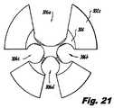
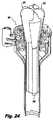
上記例示的なトロカール実施形態100の動作を説明したが、ここで、器具ガイドの使用について説明する。限定ではない例示の目的で、本明細書において具現化したようにかつ図19〜図24および図25〜図27に図示するように、2つの例示的な器具ガイド300、400が設けられている。 Having described the operation of the
図19〜図24を参照すると、器具ガイド300の第1実施形態が示されている。器具ガイドは、近位端302、半径方向に拡大したトランペット状またはフレア状近位領域302a、遠位端304および細長い遠位領域304aを有している。器具ガイドは、複数の溝306a〜306dをさらに有している。図21は器具ガイド300の遠位端304の図であり、図22は器具ガイド300の近位端302の図である。図23は、溝306aが頂部にある器具ガイドの平面図である。図示するように、溝306b、306c、306dは、器具ガイド300の遠位領域304aにおいて断面が略円形であり、溝306aは、器具ガイド300の遠位領域304aにおいて略楕円形断面を有している。図22に示すように、各溝に角度付き溝壁308が設けられている。 With reference to FIGS. 19-24, a first embodiment of an
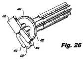
図24に示すように、使用時、器具ガイドの遠位端304は、トロカール100のボア内に導入される。所望により、バッフル160を含むサブアセンブリを取り除くことができる。しかしながら、トロカール100は、図24では、こうしたサブアセンブリを取り除くことなく図示されている。代りに、可撓性材料からなるバッフル160は、邪魔にならないところに引き伸ばされている。そのように挿入されると、器具ガイド300は、器具を支持しているロボット手術アームに対する固定入口点を提供する。各溝306の角度付き壁308は、各溝306に近づいて、その中に入る各ロボット・アームを誘導し、かつそれとの位置合せを容易にするようにより広い開口部を提供する。このように、ロボット・アームがある角度で導入される場合、溝306の壁308は、アームをトロカールのボア106内に誘導する。器具ガイド400の第2実施形態を図25〜図27に示す。器具ガイド400は、主に、トランペット状近位部を含まないが、代りに近位周方向フランジ402を含むということに関して、器具ガイド300とは異なっている。実際の外科手術用器具の代りに、複数の挿入物410が図示されている。こうした挿入物の1つを、図28に詳細に示す。本明細書で参照したすべての特許および特許出願は、あらゆる目的に対してその全体が参照により組み込まれる。 In use, the
上述し、かつ図面に示したような本開示の方法およびシステムは、従来技術のシステムに比較して優れた特性を有するトロカールおよび外科用システムを提供する。当業者には、本発明の趣旨または範囲から逸脱することなく、本発明の装置および方法においてさまざまな変更および変形を行うことができることが明らかとなろう。したがって、本発明は、開示する主題および均等物の範囲内にある修正形態および変形形態を含むことが意図されている。 The methods and systems of the present disclosure as described above and illustrated in the drawings provide trocar and surgical systems that have superior properties compared to prior art systems. It will be apparent to those skilled in the art that various modifications and variations can be made in the apparatus and method of the present invention without departing from the spirit or scope of the invention. Thus, it is intended that the present invention include modifications and variations that are within the scope of the disclosed subject matter and equivalents.
Claims (11)
Translated fromJapanesea)管状の内壁と管状の外壁とを有するトロカールであって、近位端および遠位端を有し、前記内壁が、前記トロカールを通るアクセスを提供するように中心長手方向内腔を画定し、入れ子配置で、
i)外側カニューレと、
ii)前記外側カニューレ内に配置された内側カニューレであって、前記トロカールを通るアクセスを提供するように少なくとも部分的に前記中心長手方向内腔を画定する内側カニューレと、
iii)前記外側カニューレ内に配置された管中心構成要素と、
iv)前記外側カニューレ内に配置されたた環状噴射口アセンブリであって、前記管中心構成要素および前記環状噴射口アセンブリが嵌合して、前記トロカールによって画定される中心長手方向軸を中心に環状に配置された複数のノズル通路を画定し、前記管中心構成要素および前記環状噴射口アセンブリが、加圧ガスを受け取ることができるプレナムを画定するように適合され、かつ構成され、前記プレナムが、前記ノズル通路と流体連通し、前記ノズル通路が、前記トロカールの前記遠位端に向かって前記トロカールの長手方向軸に対して平行に高速噴射を噴出するように適合され、かつ構成されている、環状噴射口アセンブリと、を含む、トロカールと、
b)前記中心長手方向内腔内に配置された器具ガイドであって、近位端、遠位端、および前記近位端から前記遠位端まで前記器具ガイドを通して画定された複数の溝を有し、かつ、前記器具ガイドが、近位領域では半径方向に拡大したトランペット形状を有し、また、遠位領域では細長い形状を有し、各溝の前記近位領域が、前記器具ガイドが前記トロカール内に挿入されると、前記トロカールの前記中心長手方向軸から角度が付けられる少なくとも1つの細長い角度付き溝壁によって画定され、外科手術用器具を前記トロカールの前記中心長手方向内腔内に誘導して受け取るように適合され、かつ構成されている、器具ガイドと、を具備するシステム。A system used in a surgical procedure,
a) a trocar having a tubular inner wall and a tubular outer wall having a proximal end and a distal end, wherein the inner wall defines a central longitudinal lumen to provide access through the trocar. , In a nested arrangement,
i) an outer cannula;
ii) an inner cannula disposed within the outer cannula, the inner cannula defining at least partially the central longitudinal lumen to provide access through the trocar;
iii) a tube center component disposed within the outer cannula;
iv) An annular jet assembly disposed within the outer cannula, wherein the tube center component and the annular jet assembly are mated and annular about a central longitudinal axis defined by the trocar A plurality of nozzle passages disposed in the tube, wherein the tube center component and the annular nozzle assembly are adapted and configured to define a plenum capable of receiving pressurized gas, the plenum comprising: In fluid communication with the nozzle passage, the nozzle passage adapted and configured to eject a high velocity jet parallel to a longitudinal axis of the trocar toward the distal end of the trocar; An annular jet assembly, and a trocar,
b) an instrument guide disposed within the central longitudinal lumen having a proximal end, a distal end, and a plurality of grooves defined through the instrument guide from the proximal end to the distal end And theinstrument guide has a radially expanded trumpet shape in the proximal region, and an elongated shape in the distal region, wherein the proximal region of each groove When inserted into a trocar, it is defined by at least one elongated angled groove wall that is angled from the central longitudinal axis of thetrocar and guidesa surgical instrument into thecentral longitudinal lumen of the trocar And an instrument guide adapted and configured to receive.
a)近位周縁ビードと、
b)遠位周縁ビードと、
c)不規則な表面によって画定された、前記近位周縁ビードおよび前記遠位周縁ビードによって境界が画された中空体であって、少なくとも1つの外科手術用器具が内部を通過するのを可能にするように偏向するように適合され、かつ構成された中空体と、を含む、請求項1に記載のシステム。A sound-absorbing baffle in the outer cannula located proximal to the nozzle passage, the sound-absorbing baffle comprising a flexible material; and a) a proximal peripheral bead;
b) a distal peripheral bead;
c) a hollow body defined by an irregular surface and bounded by the proximal peripheral bead and the distal peripheral bead, allowing at least one surgical instrument to pass therethrough; And a hollow body adapted and configured to deflect in such a manner.
b)管状の内壁と管状の外壁とを有するトロカールであって、近位端および遠位端を有し、前記内壁が、前記トロカールを通るアクセスを提供するように中心長手方向内腔を画定し、入れ子配置で、
i)外側カニューレと、
ii)前記外側カニューレ内に配置された内側カニューレであって、前記トロカールを通るアクセスを提供するように少なくとも部分的に前記中心長手方向内腔を画定する内側カニューレと、
iii)前記外側カニューレ内に配置された管中心構成要素と、
iv)前記外側カニューレ内に配置された環状噴射口アセンブリであって、前記管中心構成要素および前記環状噴射口アセンブリが嵌合して、前記トロカールによって画定される中心長手方向軸を中心に環状に配置された複数のノズル通路を画定し、前記管中心構成要素および前記環状噴射口アセンブリが、加圧ガスを受け取ることができるプレナムを画定するように適合され、かつ構成され、前記プレナムが、前記ノズル通路と流体連通し、前記ノズル通路が、前記トロカールの前記遠位端に向かって前記トロカールの長手方向軸に対して実質的に平行に高速噴射を噴出するように適合され、かつ構成されている、環状噴射口アセンブリと、を含む、トロカールと、
c)前記中心長手方向内腔内に配置された器具ガイドであって、近位端、遠位端、および前記近位端から前記遠位端まで前記器具ガイドを通して画定された複数の溝を有し、かつ、前記器具ガイドが、近位領域では半径方向に拡大したトランペット形状を有し、また、遠位領域では細長い形状を有し、各溝の前記近位領域が、前記器具ガイドが前記トロカール内に挿入されると、前記トロカールの前記中心長手方向軸から角度が付けられる少なくとも1つの細長い角度付き溝壁によって画定され、前記遠隔制御手術システムの前記遠隔制御可能なアームのうちの1つを前記トロカールの前記中心長手方向内腔内に誘導して受け取るように適合され、かつ構成されている、器具ガイドと、を具備するロボット手術システム。
a) Remotely controlled surgical system having a plurality of remotely controllable arms, each arm suitable for performing a part of a surgical procedure, each arm being remotely controllable from a user console A remote controlled surgical system;
b) A trocar having a tubular inner wall and a tubular outer wall having a proximal end and a distal end, the inner wall defining a central longitudinal lumen to provide access through the trocar. , In a nested arrangement,
i) an outer cannula;
ii) an inner cannula disposed within the outer cannula, the inner cannula defining at least partially the central longitudinal lumen to provide access through the trocar;
iii) a tube center component disposed within the outer cannula;
iv) An annular jet assembly disposed within the outer cannula, wherein the tube center component and the annular jet assembly are mated to be annular about a central longitudinal axis defined by the trocar Defining a plurality of nozzle passages disposed, wherein the tube center component and the annular nozzle assembly are adapted and configured to define a plenum capable of receiving pressurized gas, the plenum being In fluid communication with and configured to eject a high velocity jet substantially parallel to a longitudinal axis of the trocar toward the distal end of the trocar. An annular jet assembly, including a trocar;
c) an instrument guide disposed within the central longitudinal lumen having a proximal end, a distal end, and a plurality of grooves defined through the instrument guide from the proximal end to the distal end; And theinstrument guide has a radially expanded trumpet shape in the proximal region, and an elongated shape in the distal region, wherein the proximal region of each groove One of the remotely controllable arms of the remote controlled surgical systemdefined by at least one elongated angled groove wall that is angled from the central longitudinal axis of the trocar when inserted into the trocar. An instrument guide adapted and configured to guide and receive thetrocar into the central longitudinal lumen of the trocar .
Applications Claiming Priority (3)
| Application Number | Priority Date | Filing Date | Title |
|---|---|---|---|
| US34771410P | 2010-05-24 | 2010-05-24 | |
| US61/347,714 | 2010-05-24 | ||
| PCT/US2011/037814WO2012005819A1 (en) | 2010-05-24 | 2011-05-24 | Devices for automated surgery |
Publications (2)
| Publication Number | Publication Date |
|---|---|
| JP2013530742A JP2013530742A (en) | 2013-08-01 |
| JP5914466B2true JP5914466B2 (en) | 2016-05-11 |
Family
ID=44626702
Family Applications (1)
| Application Number | Title | Priority Date | Filing Date |
|---|---|---|---|
| JP2013512178AActiveJP5914466B2 (en) | 2010-05-24 | 2011-05-24 | Automatic surgical device |
Country Status (5)
| Country | Link |
|---|---|
| US (1) | US9775642B2 (en) |
| EP (1) | EP2575649B1 (en) |
| JP (1) | JP5914466B2 (en) |
| ES (1) | ES2773940T3 (en) |
| WO (1) | WO2012005819A1 (en) |
Families Citing this family (24)
| Publication number | Priority date | Publication date | Assignee | Title |
|---|---|---|---|---|
| US9078562B2 (en) | 2010-01-11 | 2015-07-14 | Minimally Invasive Devices, Inc. | Systems and methods for optimizing and maintaining visualization of a surgical field during the use of surgical scopes |
| JP5968886B2 (en) | 2010-08-04 | 2016-08-10 | ミニマリー インべーシブ デバイシーズ, インコーポレイテッド | System and method for optimizing and maintaining operative field visualization while using a surgical microscope |
| US9522017B2 (en) | 2010-12-03 | 2016-12-20 | Minimally Invasive Devices, Inc. | Devices, systems, and methods for performing endoscopic surgical procedures |
| WO2012122263A2 (en) | 2011-03-08 | 2012-09-13 | Surgiquest, Inc. | Trocar assembly with pneumatic sealing |
| ITBA20120020U1 (en)* | 2012-04-11 | 2013-10-12 | Vincenzo Nuzziello | "DOUBLE CHANNEL SURGICAL DEVICE FOR ABDOMINAL ACCESS" |
| EP2846713A1 (en) | 2012-05-09 | 2015-03-18 | EON Surgical Ltd. | Laparoscopic port |
| WO2014081783A1 (en)* | 2012-11-20 | 2014-05-30 | Surgiquest, Inc. | Systems and methods for conducting smoke evacuation during laparoscopic surgical procedures |
| WO2014151824A1 (en) | 2013-03-14 | 2014-09-25 | Minimally Invasive Devices, Inc. | Fluid dispensing control systems and methods |
| US11045633B2 (en) | 2014-04-10 | 2021-06-29 | University Health Network | Cannula for connecting medical devices to biological systems |
| US20150351737A1 (en)* | 2014-06-05 | 2015-12-10 | Jeffrey Jackson | Multi-chambered cannula |
| US9801656B2 (en)* | 2015-01-30 | 2017-10-31 | Surgiquest, Inc. | Self-adjusting pneumatically sealed trocar |
| JP6871279B2 (en)* | 2016-07-11 | 2021-05-12 | コンメッド コーポレーション | Cannula assembly for robot-assisted pressure-controlled laparoscopic surgery |
| US10806490B2 (en)* | 2017-03-08 | 2020-10-20 | Conmed Corporation | Single lumen gas sealed access port for use during endoscopic surgical procedures |
| US20190000501A1 (en)* | 2017-07-03 | 2019-01-03 | Bryan Nowroozi | Systems, devices and methods for accessing a body |
| US10792069B2 (en)* | 2017-09-26 | 2020-10-06 | Ethicon Llc | Trocar seal assemblies |
| US11471186B2 (en)* | 2018-06-27 | 2022-10-18 | Luiz Lanat Pedreira de Cerqueira Filho | Thin cannulas trocar and method |
| AU2019385568A1 (en)* | 2018-11-21 | 2020-11-26 | Buffalo Filter Llc | Apparatus and method for filtering |
| CN116687529A (en)* | 2019-03-26 | 2023-09-05 | 康美公司 | Gas circulation system with gas-tight access cover and valve-tight access cover for robotic-assisted surgery |
| USD956219S1 (en) | 2020-07-10 | 2022-06-28 | Covidien Lp | Port apparatus |
| USD963851S1 (en) | 2020-07-10 | 2022-09-13 | Covidien Lp | Port apparatus |
| US11957378B1 (en) | 2020-12-18 | 2024-04-16 | Northgate Technologies, Inc. | Anti-microbial surgical access device |
| CA3218246A1 (en) | 2021-07-20 | 2023-01-26 | Ashish Sinha | Cannulas for ophthalmic procedures |
| WO2023021408A1 (en)* | 2021-08-16 | 2023-02-23 | Fisher & Paykel Healthcare Limited | Accessory for arranging a surgical instrument within a cannula shaft |
| CN115813502A (en)* | 2022-11-22 | 2023-03-21 | 微至(苏州)医疗科技有限公司 | Puncture outfit sleeve pipe and puncture outfit with same |
Family Cites Families (37)
| Publication number | Priority date | Publication date | Assignee | Title |
|---|---|---|---|---|
| US5454365A (en)* | 1990-11-05 | 1995-10-03 | Bonutti; Peter M. | Mechanically expandable arthroscopic retractors |
| US5025778A (en)* | 1990-03-26 | 1991-06-25 | Opielab, Inc. | Endoscope with potential channels and method of using the same |
| US5141498A (en)* | 1991-09-10 | 1992-08-25 | Unisurge, Incorporated | Flexible valve and device incorporating the same |
| US5197955A (en)* | 1991-10-18 | 1993-03-30 | Ethicon, Inc. | Universal seal for trocar assembly |
| US5395367A (en)* | 1992-07-29 | 1995-03-07 | Wilk; Peter J. | Laparoscopic instrument with bendable shaft and removable actuator |
| US5312391A (en)* | 1992-07-29 | 1994-05-17 | Wilk Peter J | Laparoscopic instrument assembly |
| US5762458A (en) | 1996-02-20 | 1998-06-09 | Computer Motion, Inc. | Method and apparatus for performing minimally invasive cardiac procedures |
| US5720730A (en)* | 1995-09-01 | 1998-02-24 | Blake, Iii; Joseph W. | Lubricated trocar valve |
| US5746720A (en)* | 1995-10-18 | 1998-05-05 | Stouder, Jr.; Albert E. | Method and apparatus for insertion of a cannula and trocar |
| US5855583A (en) | 1996-02-20 | 1999-01-05 | Computer Motion, Inc. | Method and apparatus for performing minimally invasive cardiac procedures |
| US5792135A (en) | 1996-05-20 | 1998-08-11 | Intuitive Surgical, Inc. | Articulated surgical instrument for performing minimally invasive surgery with enhanced dexterity and sensitivity |
| DE19627992A1 (en)* | 1996-07-11 | 1998-01-22 | Storz Karl Gmbh & Co | Instrument with two independent jaws |
| WO1998022040A1 (en)* | 1996-11-19 | 1998-05-28 | Uroplasty, Inc. | Instrument for guiding delivery of injectable materials in treating urinary incontinence |
| US7666191B2 (en) | 1996-12-12 | 2010-02-23 | Intuitive Surgical, Inc. | Robotic surgical system with sterile surgical adaptor |
| US6277064B1 (en)* | 1997-12-30 | 2001-08-21 | Inbae Yoon | Surgical instrument with rotatably mounted offset endoscope |
| DE19800917A1 (en)* | 1998-01-14 | 1999-07-15 | Storz Karl Gmbh & Co | Instrument for insertion during endoscopic operations |
| DE10037421C2 (en)* | 2000-07-21 | 2003-06-26 | Leonid Sverdlov | Device for minimally invasive access to the organs of the abdominal cavity |
| US6726699B1 (en)* | 2000-08-15 | 2004-04-27 | Computer Motion, Inc. | Instrument guide |
| JP2002209835A (en)* | 2001-01-15 | 2002-07-30 | Fuji Photo Optical Co Ltd | Intercelom diagnostic device |
| US7854724B2 (en)* | 2003-04-08 | 2010-12-21 | Surgiquest, Inc. | Trocar assembly with pneumatic sealing |
| US7182752B2 (en) | 2003-04-08 | 2007-02-27 | Surgiquest, Incorporated | Continuous gas flow trocar assembly |
| US7338473B2 (en) | 2003-04-08 | 2008-03-04 | Surgiquest, Incorporated | Pneumoseal trocar arrangement |
| US7285112B2 (en) | 2003-04-08 | 2007-10-23 | Surgiquest, Incorporated | Gas flow trocar arrangement |
| US7850600B1 (en)* | 2003-09-23 | 2010-12-14 | Tyco Healthcare Group Lp | Laparoscopic instrument and trocar system and related surgical method |
| JP4922164B2 (en)* | 2004-07-21 | 2012-04-25 | タイコ ヘルスケア グループ リミテッド パートナーシップ | Introducer assembly with pendant seal |
| US7453227B2 (en) | 2005-12-20 | 2008-11-18 | Intuitive Surgical, Inc. | Medical robotic system with sliding mode control |
| US7689320B2 (en) | 2005-12-20 | 2010-03-30 | Intuitive Surgical Operations, Inc. | Robotic surgical system with joint motion controller adapted to reduce instrument tip vibrations |
| US8357085B2 (en)* | 2009-03-31 | 2013-01-22 | Ethicon Endo-Surgery, Inc. | Devices and methods for providing access into a body cavity |
| US8690831B2 (en)* | 2008-04-25 | 2014-04-08 | Ethicon Endo-Surgery, Inc. | Gas jet fluid removal in a trocar |
| US8518024B2 (en)* | 2006-04-24 | 2013-08-27 | Transenterix, Inc. | System and method for multi-instrument surgical access using a single access port |
| US8795235B2 (en)* | 2006-10-06 | 2014-08-05 | Surgiquest, Inc. | Devices for and methods of performing minimally-invasive surgical procedures through a single incision |
| EP2134238B1 (en)* | 2007-04-17 | 2016-08-03 | SurgiQuest, Incorporated | Endoluminal and transluminal surgical devices |
| WO2009021297A1 (en)* | 2007-08-16 | 2009-02-19 | Paiva Araujo Dos Scheiba-Zorro | Conductor platform for natural orifice surgery |
| KR101829726B1 (en)* | 2008-10-10 | 2018-02-19 | 서지퀘스트, 인코포레이티드 | Low-profile surgical access devices with anchoring |
| JP5733831B2 (en)* | 2008-10-10 | 2015-06-10 | サージクェスト,インコーポレーテッド | System and method for improved gas recirculation in a surgical trocar with a gas sealing mechanism |
| US8075528B2 (en)* | 2008-10-30 | 2011-12-13 | Ethicon Endo-Surgery, Inc. | Surgical access port with flexible sealing cannula |
| US20110124968A1 (en)* | 2009-11-24 | 2011-05-26 | Tyco Healthcare Group Lp | Surgical portal and introducer assembly |
- 2011
- 2011-05-24JPJP2013512178Apatent/JP5914466B2/enactiveActive
- 2011-05-24WOPCT/US2011/037814patent/WO2012005819A1/enactiveApplication Filing
- 2011-05-24ESES11723835Tpatent/ES2773940T3/enactiveActive
- 2011-05-24EPEP11723835.2Apatent/EP2575649B1/enactiveActive
- 2011-05-24USUS13/704,411patent/US9775642B2/enactiveActive
Also Published As
| Publication number | Publication date |
|---|---|
| ES2773940T3 (en) | 2020-07-15 |
| US20140088491A1 (en) | 2014-03-27 |
| US9775642B2 (en) | 2017-10-03 |
| WO2012005819A1 (en) | 2012-01-12 |
| EP2575649B1 (en) | 2019-12-18 |
| EP2575649A1 (en) | 2013-04-10 |
| JP2013530742A (en) | 2013-08-01 |
Similar Documents
| Publication | Publication Date | Title |
|---|---|---|
| JP5914466B2 (en) | Automatic surgical device | |
| JP6959968B2 (en) | Multi-lumen tube set for gas circulation systems with single lumen gas sealed access port and single lumen valve sealed access port | |
| JP7210485B2 (en) | Trocar with angled needle insertion port and vertical seal latch | |
| US9907569B2 (en) | Trocar assembly with pneumatic sealing | |
| US20200060672A1 (en) | Methods and Devices for Providing Access into a Body Cavity | |
| JP6037596B2 (en) | Foam port device having a closed end lumen | |
| JP5132072B2 (en) | Introducer seal assembly with low profile gimbal seal | |
| JP2019521771A (en) | Cannula assembly for robot-assisted pressure-controlled laparoscopic surgery | |
| EP3700443A1 (en) | Devices for performing minimally invasive surgery having rotating multiport access | |
| AU2018355094A1 (en) | Devices for performing minimally invasive surgery having foam support housing | |
| JP2012200605A (en) | Holding member for laparoscope access device | |
| EP3700444B1 (en) | Devices for performing minimally invasive surgery having bellows support housing | |
| JP2025111839A (en) | Gas-tight access cap for robotic cannula | |
| JP2024085540A (en) | Suction equipment |
Legal Events
| Date | Code | Title | Description |
|---|---|---|---|
| A621 | Written request for application examination | Free format text:JAPANESE INTERMEDIATE CODE: A621 Effective date:20140421 | |
| A977 | Report on retrieval | Free format text:JAPANESE INTERMEDIATE CODE: A971007 Effective date:20141121 | |
| A131 | Notification of reasons for refusal | Free format text:JAPANESE INTERMEDIATE CODE: A131 Effective date:20150106 | |
| A521 | Request for written amendment filed | Free format text:JAPANESE INTERMEDIATE CODE: A523 Effective date:20150323 | |
| A131 | Notification of reasons for refusal | Free format text:JAPANESE INTERMEDIATE CODE: A131 Effective date:20150908 | |
| A521 | Request for written amendment filed | Free format text:JAPANESE INTERMEDIATE CODE: A523 Effective date:20151015 | |
| TRDD | Decision of grant or rejection written | ||
| A01 | Written decision to grant a patent or to grant a registration (utility model) | Free format text:JAPANESE INTERMEDIATE CODE: A01 Effective date:20160308 | |
| A61 | First payment of annual fees (during grant procedure) | Free format text:JAPANESE INTERMEDIATE CODE: A61 Effective date:20160404 | |
| R150 | Certificate of patent or registration of utility model | Ref document number:5914466 Country of ref document:JP Free format text:JAPANESE INTERMEDIATE CODE: R150 | |
| R250 | Receipt of annual fees | Free format text:JAPANESE INTERMEDIATE CODE: R250 | |
| R250 | Receipt of annual fees | Free format text:JAPANESE INTERMEDIATE CODE: R250 | |
| R250 | Receipt of annual fees | Free format text:JAPANESE INTERMEDIATE CODE: R250 | |
| R250 | Receipt of annual fees | Free format text:JAPANESE INTERMEDIATE CODE: R250 | |
| R250 | Receipt of annual fees | Free format text:JAPANESE INTERMEDIATE CODE: R250 | |
| R250 | Receipt of annual fees | Free format text:JAPANESE INTERMEDIATE CODE: R250 | |
| R250 | Receipt of annual fees | Free format text:JAPANESE INTERMEDIATE CODE: R250 |