JP5912654B2 - Substrate holding device, pattern transfer device, and pattern transfer method - Google Patents
Substrate holding device, pattern transfer device, and pattern transfer methodDownload PDFInfo
- Publication number
- JP5912654B2 JP5912654B2JP2012039074AJP2012039074AJP5912654B2JP 5912654 B2JP5912654 B2JP 5912654B2JP 2012039074 AJP2012039074 AJP 2012039074AJP 2012039074 AJP2012039074 AJP 2012039074AJP 5912654 B2JP5912654 B2JP 5912654B2
- Authority
- JP
- Japan
- Prior art keywords
- substrate
- main surface
- unit
- pattern
- state
- Prior art date
- Legal status (The legal status is an assumption and is not a legal conclusion. Google has not performed a legal analysis and makes no representation as to the accuracy of the status listed.)
- Active
Links
Images


Classifications
- G—PHYSICS
- G03—PHOTOGRAPHY; CINEMATOGRAPHY; ANALOGOUS TECHNIQUES USING WAVES OTHER THAN OPTICAL WAVES; ELECTROGRAPHY; HOLOGRAPHY
- G03F—PHOTOMECHANICAL PRODUCTION OF TEXTURED OR PATTERNED SURFACES, e.g. FOR PRINTING, FOR PROCESSING OF SEMICONDUCTOR DEVICES; MATERIALS THEREFOR; ORIGINALS THEREFOR; APPARATUS SPECIALLY ADAPTED THEREFOR
- G03F7/00—Photomechanical, e.g. photolithographic, production of textured or patterned surfaces, e.g. printing surfaces; Materials therefor, e.g. comprising photoresists; Apparatus specially adapted therefor
- G03F7/70—Microphotolithographic exposure; Apparatus therefor
- G03F7/70691—Handling of masks or workpieces
- G03F7/70783—Handling stress or warp of chucks, masks or workpieces, e.g. to compensate for imaging errors or considerations related to warpage of masks or workpieces due to their own weight
- G—PHYSICS
- G03—PHOTOGRAPHY; CINEMATOGRAPHY; ANALOGOUS TECHNIQUES USING WAVES OTHER THAN OPTICAL WAVES; ELECTROGRAPHY; HOLOGRAPHY
- G03F—PHOTOMECHANICAL PRODUCTION OF TEXTURED OR PATTERNED SURFACES, e.g. FOR PRINTING, FOR PROCESSING OF SEMICONDUCTOR DEVICES; MATERIALS THEREFOR; ORIGINALS THEREFOR; APPARATUS SPECIALLY ADAPTED THEREFOR
- G03F7/00—Photomechanical, e.g. photolithographic, production of textured or patterned surfaces, e.g. printing surfaces; Materials therefor, e.g. comprising photoresists; Apparatus specially adapted therefor
- G03F7/70—Microphotolithographic exposure; Apparatus therefor
- G03F7/70691—Handling of masks or workpieces
- G03F7/707—Chucks, e.g. chucking or un-chucking operations or structural details
Landscapes
- Physics & Mathematics (AREA)
- General Physics & Mathematics (AREA)
- Container, Conveyance, Adherence, Positioning, Of Wafer (AREA)
- Exposure And Positioning Against Photoresist Photosensitive Materials (AREA)
- Exposure Of Semiconductors, Excluding Electron Or Ion Beam Exposure (AREA)
Description
Translated fromJapanese本発明の実施形態は、基板保持装置及びパターン転写装置並びにパターン転写方法に関する。 Embodiments described herein relate generally to a substrate holding device, a pattern transfer device, and a pattern transfer method.
半導体リソグラフィ工程において、基板(半導体ウェーハ)上に所定のパターンを転写させるパターン転写装置が用いられる。パターン転写装置は、基板を着脱可能に保持する基板保持装置を含む。半導体リソグラフィ工程において、予め基板に形成されたパターンの上に、新たなパターンを転写させる場合の精度(以下、重ね合わせ精度と称す)の向上が望まれる。重ね合わせ精度を低下させる要因に、基板の歪みがある。基板保持装置及びパターン転写装置において、基板の歪みを適切に調整することが望まれる。 In a semiconductor lithography process, a pattern transfer apparatus that transfers a predetermined pattern onto a substrate (semiconductor wafer) is used. The pattern transfer device includes a substrate holding device that detachably holds a substrate. In a semiconductor lithography process, it is desired to improve the accuracy (hereinafter referred to as overlay accuracy) when a new pattern is transferred onto a pattern previously formed on a substrate. A factor that lowers the overlay accuracy is substrate distortion. In the substrate holding device and the pattern transfer device, it is desired to appropriately adjust the distortion of the substrate.
本発明の実施形態は、保持された基板の歪みを適切に調整できる基板保持装置及びパターン転写装置並びにパターン転写方法を提供する。 Embodiments of the present invention provide a substrate holding device, a pattern transfer device, and a pattern transfer method that can appropriately adjust the strain of the held substrate.
本発明の実施形態によれば、本体部と、複数の第1支持部と、を備えた基板保持装置が提供される。前記本体部は、主面を有する。前記本体部は、板状である。前記複数の第1支持部は、前記主面上に配置される。前記複数の第1支持部のそれぞれは、基板を吸着可能な吸着部と、前記主面に対して垂直な第1方向に前記吸着部を移動させる垂直方向駆動部と、前記主面に対して平行な第2方向に前記吸着部を移動させる平行方向駆動部と、を有する。前記吸着部は、独立して前記第1方向及び前記第2方向に移動可能である。
According to the embodiment of the present invention, a substrate holding device including a main body portion and a plurality of first support portions is provided. The main body has a main surface. The main body has a plate shape. The plurality of first support portions are disposed on the main surface. Each of the plurality of first support portions includes a suction portion capable of sucking a substrate,a vertical driving portion that moves the suction portion in a first direction perpendicular to the main surface, and the main surface. A parallel direction drive unit that moves the suction unit in a parallel second direction . The suction part isindependently movable in the first direction and the second direction .
以下に、各実施の形態について図面を参照しつつ説明する。
なお、図面は模式的または概念的なものであり、各部分の厚みと幅との関係、部分間の大きさの比率などは、必ずしも現実のものと同一とは限らない。また、同じ部分を表す場合であっても、図面により互いの寸法や比率が異なって表される場合もある。
なお、本願明細書と各図において、既出の図に関して前述したものと同様の要素には同一の符号を付して詳細な説明は適宜省略する。Each embodiment will be described below with reference to the drawings.
The drawings are schematic or conceptual, and the relationship between the thickness and width of each part, the size ratio between the parts, and the like are not necessarily the same as actual ones. Further, even when the same part is represented, the dimensions and ratios may be represented differently depending on the drawings.
Note that, in the present specification and each drawing, the same elements as those described above with reference to the previous drawings are denoted by the same reference numerals, and detailed description thereof is omitted as appropriate.
(第1の実施形態)
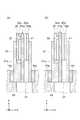
図1(a)及び図1(b)は、第1の実施形態に係る基板保持装置の構成を例示する模式図である。
図1(a)は、模式的上面図であり、図1(b)は、模式的断面図である。
図1(a)及び図1(b)に表したように、本実施形態に係る基板保持装置110は、本体部10と、複数の第1支持部11と、を備える。
基板保持装置110は、基板5を着脱可能に保持する。基板5は、例えば、板状である。より詳しくは、円板状である。基板5は、例えば、半導体ウェーハである。基板保持装置110は、例えば、半導体リソグラフィ工程において、パターンを転写させる基板5の保持に用いられる。(First embodiment)
FIG. 1A and FIG. 1B are schematic views illustrating the configuration of the substrate holding device according to the first embodiment.
FIG. 1A is a schematic top view, and FIG. 1B is a schematic cross-sectional view.
As shown in FIG. 1A and FIG. 1B, the
The board | substrate holding |
本体部10は、例えば、板状である。より詳しくは、円板状である。本体部10は、基板5と対向する主面10aを有する。本体部10の主面10aの径は、例えば、基板5の径よりも大きい。すなわち、主面10aの面積は、基板5の主面5aの面積よりも広い。 The
以下、この例では、主面10aに対して垂直な第1方向をZ軸方向とする。Z軸方向に対して垂直な1つの方向をX軸方向とする。Z軸方向及びX軸方向に対して垂直な方向をY軸方向とする。この例では、例えば、X軸方向が、第2方向である。例えば、Y軸方向が、第3方向である。 Hereinafter, in this example, the first direction perpendicular to the
複数の第1支持部11は、本体部10に設けられる。複数の第1支持部11は、例えば、主面10aに所定のパターンで配置される。第1支持部11は、吸引を行うための吸引口20aを有する先端部20を含む。第1支持部11は、例えば、吸引管路21を含む。第1支持部11は、例えば、筒状である。先端部20は、例えば、筒状の第1支持部11の先端面20bである。吸引口20aは、例えば、吸引管路21のうちの、先端面20bに露呈された部分である。第1支持部11は、吸引口20aの吸引によって先端部20に吸着させることにより、板状の基板5を支持する。すなわち、第1支持部11において、先端部20は、基板5を吸着可能な吸着部22である。 The plurality of
吸引管路21は、本体部10の内部に設けられた排気管路10bに接続される。複数の第1支持部11のそれぞれの吸引管路21は、例えば、排気管路10bにおいて、1本にまとめられる。排気管路10bは、例えば、図示を省略した配管などを介して、ポンプ6に接続される。これにより、ポンプ6から排気管路10b及び吸引管路21を介して吸引口20aへと至る経路が形成される。ポンプ6は、排気管路10bに対して負圧を付与する。これにより、ポンプ6の駆動によって、吸引口20aから吸引が行われる。 The
例えば、ポンプ6から吸引口20aに至る管路内を負圧にすることで、複数の第1支持部11のそれぞれに、基板5が吸着保持される。例えば、ポンプ6から吸引口20aに至る管路内を大気圧に戻すことで、複数の第1支持部11による基板5の吸着が解除される。これにより、基板保持装置110において、基板5が、着脱可能に保持される。 For example, the
ポンプ6は、例えば、基板保持装置110に内蔵させてもよい。この例では、ポンプ6の駆動により、複数の第1支持部11のそれぞれの吸引口20aから同時に吸引が行われる。例えば、吸引管路21を開閉するバルブを複数の第1支持部11のそれぞれに設けることにより、吸引を行う吸引口20aを選択できるようにしてもよい。また、複数の第1支持部11のそれぞれにポンプを設け、それらのポンプの駆動を制御することによって、吸引を行う吸引口20aを選択できるようにしてもよい。 For example, the
図2(a)及び図2(b)は、第1の実施形態に係る基板保持装置の一部の構成を例示する模式的断面図である。
図2(a)及び図2(b)に表したように、第1支持部11は、例えば、第1筒部31と、第2筒部32と、第1垂直方向駆動部41と、を含む。
第1筒部31及び第2筒部32は、例えば、Z軸方向に沿う筒状である。第1筒部31は、本体部10に取り付けられる。第1筒部31の内径は、例えば、第2筒部32の外径と実質的に同じである。第2筒部32は、第1筒部31の内部に嵌っている。第2筒部32は、第1筒部31にガイドされ、Z軸方向に移動する。この例において、先端部20は、第2筒部32に形成される。吸引管路21は、第1筒部31の内部空間と、第2筒部32の内部空間と、によって形成される。第1筒部31は、内側に向かって突出する突出部31aを有する。第2筒部32は、内側に向かって突出する突出部32aを有する。2A and 2B are schematic cross-sectional views illustrating the configuration of a part of the substrate holding device according to the first embodiment.
As shown in FIG. 2A and FIG. 2B, the
The
第1垂直方向駆動部41は、例えば、圧電素子である。第1垂直方向駆動部41は、例えば、入力された電圧に応じてZ軸方向に伸縮する。第1垂直方向駆動部41の一端は、突出部31aを介して第1筒部31に固定されている。第1垂直方向駆動部41の他端は、突出部32aを介して第2筒部32に固定されている。従って、第1垂直方向駆動部41を伸縮させると、第2筒部32がZ軸方向に移動する。 The first
第1垂直方向駆動部41の先端41aは、先端面20bよりも僅かに突出している。こうすれば、先端面20bを基板5に接触させる場合に比べて、基板5に対する接触面積が、小さくなる。これにより、基板5を第1支持部11に支持させる場合の、基板5の傷付きを抑えることができる。この例において、先端41aは、平面状に形成されている。 The tip 41a of the first
先端部20(吸着部22)は、主面10aからみたZ軸方向に沿う高さが低い第1状態と、主面10aからみたZ軸方向に沿う高さが第1状態よりも高い第2状態と、の間で、Z軸方向に沿って移動可能である。 The tip portion 20 (suction portion 22) has a first state in which the height along the Z-axis direction as viewed from the
以下、第1状態の先端部20の位置を基準位置と称す。第2状態の先端部20の位置を突出位置と称す。すなわち、第1支持部11は、基準位置と、基準位置よりも主面10aから突出させた突出位置と、の間で、Z軸方向に先端部20を移動させる。この例において、基準位置は、例えば、図2(a)に表した位置である。突出位置は、例えば、図2(b)に表した位置である。この例において、基準位置は、主面10aから突出している。突出位置は、例えば、基準位置よりもさらに主面10aから突出させた位置である。すなわち、主面10aと突出位置との間の距離は、主面10aと基準位置との間の距離よりも長い。先端部20のZ軸方向の移動量(第1垂直方向駆動部41の伸び量)は、例えば、100μm以上300μm以下である。 Hereinafter, the position of the
図3(a)〜図3(c)は、第1の実施形態に係る基板保持装置の一部の構成を例示する模式的上面図である。
図3(a)〜図3(c)に表したように、第1支持部11は、主面10aと平行な方向に先端部20を移動させるための平行方向駆動部42を、さらに含む。
平行方向駆動部42は、X軸方向に先端部20を移動させるX軸方向駆動部43と、Y軸方向に先端部20を移動させるY軸方向駆動部44と、を含む。FIG. 3A to FIG. 3C are schematic top views illustrating the configuration of part of the substrate holding device according to the first embodiment.
As shown in FIGS. 3A to 3C, the
The parallel
第1筒部31は、例えば、四角柱に円柱状の貫通孔を形成した筒体である。本体部10には、第1支持部11を配置するための矩形状の開口10cが形成される。開口10cにおいて、例えば、2つの側面は、X軸方向を向き、残りの2つの側面は、Y軸方向を向く。第1支持部11の一部は、開口10c内に入り込む。第1支持部11において、例えば、2つの側面は、X軸方向を向き、残りの2つの側面は、Y軸方向を向く。 The
X軸方向駆動部43は、第1筒部31のうちのX軸方向を向く1つの側面に取り付けられる。X軸方向駆動部43は、開口10cのX軸方向を向く側面に取り付けられる。この際、X軸方向駆動部43は、例えば、図示を省略したレールなどを介して、Y軸方向にスライド可能に開口10cの側面に取り付けられる。 The X-axis
Y軸方向駆動部44は、第1筒部31のうちのY軸方向を向く1つの側面に取り付けられる。Y軸方向駆動部44は、開口10cのY軸方向を向く側面に取り付けられる。この際、Y軸方向駆動部44は、例えば、図示を省略したレールなどを介して、X軸方向にスライド可能に開口10cの側面に取り付けられる。
このように、第1支持部11は、X軸方向駆動部43及びY軸方向駆動部44を介して、X軸方向及びY軸方向に沿って移動可能に本体部10に取り付けられる。The Y-axis
As described above, the
X軸方向駆動部43及びY軸方向駆動部44は、例えば、圧電素子である。X軸方向駆動部43は、例えば、入力された電圧に応じてX軸方向に伸縮する。Y軸方向駆動部44は、例えば、入力された電圧に応じてY軸方向に伸縮する。 The X-axis
図3(a)は、X軸方向駆動部43とY軸方向駆動部44とが、最も縮んだ状態を表している。図3(b)に表したように、X軸方向駆動部43を伸長させると、第1筒部31及び第2筒部32が、X軸方向に移動する。図3(c)に表したように、Y軸方向駆動部44を伸長させると、第1筒部31及び第2筒部32が、Y軸方向に移動する。 FIG. 3A shows a state in which the X-axis
このように、第1支持部11は、X軸方向駆動部43及びY軸方向駆動部44の駆動により、主面10aと平行な方向(X−Y平面に沿う方向)に先端部20を移動させる。先端部20のX軸方向の移動量(X軸方向駆動部43の伸び量)は、例えば、10μm以下である。先端部20のY軸方向の移動量(Y軸方向駆動部44の伸び量)は、例えば、10μm以下である。 Thus, the
X−Y平面に沿う方向における先端部20の移動方向は、X軸方向及びY軸方向に限定されない。先端部20は、例えば、主面10aの放射方向と、径方向と、に移動させてもよい。先端部20の移動方向は、X−Y平面に沿う任意の1つ以上の方向でよい。 The moving direction of the
基板保持装置110は、複数の第2支持部12を、さらに備える。第2支持部12は、本体部10に設けられる。複数の第2支持部12は、例えば、主面10aに所定のパターンで配置される。 The
図4(a)及び図4(b)は、第1の実施形態に係る基板保持装置の一部の構成を例示する模式的断面図である。
図4(a)及び図4(b)に表したように、第2支持部12は、例えば、可動部51と、第2垂直方向駆動部52と、を含む。
可動部51は、例えば、Z軸方向に沿って延びる棒状である。可動部51は、例えば、Z軸方向に移動可能に本体部10に取り付けられる。第2垂直方向駆動部52は、可動部51に駆動力を付与し、可動部51をZ軸方向に移動させる。第2垂直方向駆動部52には、例えば、圧電素子、モータ、または、ソレノイドなどが用いられる。FIG. 4A and FIG. 4B are schematic cross-sectional views illustrating the configuration of part of the substrate holding device according to the first embodiment.
As shown in FIGS. 4A and 4B, the
The
第2支持部12は、第1状態の吸着部22の位置から第2状態の吸着部22の位置に向かう方向の端51aを有する。端51aは、例えば、上端である。端51aは、主面10aからみたZ軸方向に沿う高さが第1状態の高さよりも低い第3状態と、主面10aからみたZ軸方向に沿う高さが第2状態の高さよりも高い第4状態と、を有する。
The
以下、第3状態の端51aの位置を第1位置と称す。第4状態の端51aの位置を第2位置と称す。すなわち、第2支持部12は、第2垂直方向駆動部52の駆動により、第1支持部11の基準位置よりも突出しない第1位置と、第1支持部11の突出位置よりも主面10aから突出させた第2位置と、の間で、Z軸方向に可動部51を移動させる。 Hereinafter, the position of the
第1位置にある可動部51の端51aは、基準位置にある第1支持部11の先端部20よりも主面10aから突出しない。第1位置にある端51aの主面10aからの高さは、基準位置にある先端部20の主面10aからの高さと実質的に同じでもよい。第1位置は、例えば、図4(a)に表した位置である。 The
第2位置にある可動部51の端51aは、突出位置にある第1支持部11の先端部20よりも主面10aから突出する。第2位置は、例えば、図4(b)に表した位置である。 The
複数の第2支持部12は、それぞれの端51aを基板5に接触させることにより、基板5を支持する。第2支持部12は、例えば、搬送装置(図示は省略)などから基板5を受け取る場合に用いられる。基板保持装置110では、例えば、基板5を受け取る場合に、複数の第2支持部12の可動部51を第2位置に移動させ、複数の第2支持部12に基板5を支持させる。複数の第2支持部12は、基板5を支持した状態で、第2位置から第1位置に、それぞれの可動部51を移動させる。複数の第2支持部12は、第1位置に移動する間に、支持した基板5を複数の第1支持部11に受け渡す。このように、複数の第2支持部12は、搬送装置などから基板5を受け取り、その基板5を複数の第1支持部11に案内する。なお、複数の第2支持部12のそれぞれに、基板5を吸着する機構を設けてもよい。 The plurality of
基板保持装置110は、第3支持部13を、さらに備える。第3支持部13は、本体部10の主面10aに設けられる。第3支持部13は、例えば、円環状の突起である。第3支持部13の径は、例えば、基板5の径に対応する。第3支持部13は、例えば、複数の第1支持部11に保持された基板5の外周部5eと対向する位置に設けられる。第3支持部13の先端13aの主面10aからの高さは、例えば、基準位置にある第1支持部11の先端部20の主面10aからの高さよりも低い。第3支持部13は、例えば、複数の第1支持部11の上に載せられた基板5が傾いた場合などに、基板5と接触し、基板5の外周部5e付近を支持する。第3支持部13は、環状に限らず、例えば、部分的に途切れていてもよい。 The
基板保持装置110は、第1計測部61と、第2計測部62と、をさらに備える。
第1計測部61は、複数の第1支持部11のそれぞれの先端部20の主面10aからの高さを計測する。第1計測部61は、例えば、発光部61aと、受光部61bと、を含む。第1計測部61は、例えば、発光部61aから照射される光を受光部61bで受光し、その受光の具合によって先端部20の高さを計測する光学センサである。The
The
発光部61a及び受光部61bは、例えば、複数の第1支持部11に対応させて複数設ける。例えば、それら複数の発光部61a及び複数の受光部61bによって、複数の第1支持部11のそれぞれの先端部20の高さを計測する。例えば、第1計測部61または本体部10を移動させ、第1計測部61と複数の第1支持部11との相対的な位置を調整する。これにより、例えば、1つの発光部61a及び1つの受光部61bによって、複数の第1支持部11のそれぞれの先端部20の高さを計測してもよい。第1計測部61は、光学センサに限ることなく、先端部20の高さを計測可能な任意のセンサでよい。 For example, a plurality of light emitting
第2計測部62は、複数の第1支持部11のそれぞれの先端部20のX−Y平面に沿う方向の位置を計測する。第2計測部62は、例えば、先端部20のX軸方向の位置を計測するX軸方向計測部63と、先端部20のY軸方向の位置を計測するY軸方向計測部64と、を含む。X軸方向計測部63及びY軸方向計測部64には、例えば、反射型の光学センサが用いられる。X軸方向計測部63及びY軸方向計測部64は、先端部20の位置を計測可能な任意のセンサでよい。 The
X軸方向計測部63及びY軸方向計測部64は、複数の第1支持部11の数に合わせて複数設けることにより、複数の第1支持部11のそれぞれの先端部20の位置を計測してもよい。X軸方向計測部63と複数の第1支持部11のそれぞれとの相対的な位置、及びY軸方向計測部64と複数の第1支持部11のそれぞれとの相対的な位置を調整することにより、それぞれ1つで複数の第1支持部11のそれぞれの先端部20の位置を計測してもよい。 A plurality of X-axis
第1計測部61は、例えば、第1垂直方向駆動部41についての、ゼロ点や動作の線形性などの校正に用いられる。X軸方向計測部63は、例えば、X軸方向駆動部43についての、ゼロ点や動作の線形性などの校正に用いられる。同様に、Y軸方向計測部64は、例えば、Y軸方向駆動部44についての、ゼロ点や動作の線形性などの校正に用いられる。 The
基板保持装置110においては、複数の第1支持部11に基板5を支持させた後、第1垂直方向駆動部41を駆動し、複数の第1支持部11のそれぞれの先端部20のZ軸方向の位置を調整する。X軸方向駆動部43を駆動し、複数の第1支持部11のそれぞれの先端部20のX軸方向の位置を調整する。さらに、Y軸方向駆動部44を駆動し、複数の第1支持部11のそれぞれの先端部20のY軸方向の位置を調整する。 In the
このように、基板保持装置110では、先端部20のX軸方向、Y軸方向及びZ軸方向の位置を調整することができる。これにより、基板保持装置110では、保持された基板5の歪みを適切に調整することができる。すなわち、基板保持装置110では、保持された基板5の歪みを適切に抑えることができる。 Thus, in the
先端部20の位置の調整は、例えば、第1支持部11や第2支持部12に支持される前の基板5の形状を予め測定した測定情報に基づいて行う。測定情報は、例えば、基板5の三次元形状を測定することができる測定装置において、予め測定しておく。 Adjustment of the position of the front-end | tip
先端部20の位置の調整の際に、例えば、第1計測部61及び第2計測部62で先端部20の位置を計測する。第1計測部61及び第2計測部62の計測結果を基に、第1垂直方向駆動部41、X軸方向駆動部43及びY軸方向駆動部44の駆動にフィードバックをかける。これにより、先端部20の位置の調整精度が向上し、基板5の歪みを、より適切に抑えることができる。 When adjusting the position of the
次に、複数の第2支持部12のうちのいずれかを選択的に用いて、基板5を支持する場合について説明する。
ここで、複数の第2支持部12を、第1グループ12aと第2グループ12bとの2つのグループに分ける(図1参照)。
第1グループ12aは、主面10aの中心に対して比較的外側に位置する第2支持部12である。第2グループ12bは、主面10aの中心に対して比較的内側に位置する第2支持部12である。Next, a case where the
Here, the plurality of
The
図5(a)〜図5(d)は、第1の実施形態に係る基板保持装置の構成を例示する模式的断面図である。
図5(a)に表したように、中心付近において上向きに盛り上がるように歪んだ基板5を、第1グループ12aの第2支持部12で支持する。
図5(b)に表したように、第1グループ12aの第2支持部12の可動部51を、第2位置から第1位置に移動させ、複数の第1支持部11に基板5を支持させる。この場合、比較的大きな歪みが、基板5に残ってしまう。FIG. 5A to FIG. 5D are schematic cross-sectional views illustrating the configuration of the substrate holding device according to the first embodiment.
As shown in FIG. 5A, the
As shown in FIG. 5B, the
図5(c)に表したように、中心付近において上向きに突出するように歪んだ基板5を、第2グループ12bの第2支持部12で支持する。
図5(d)に表したように、第2グループ12bの第2支持部12の可動部51を、第2位置から第1位置に移動させ、複数の第1支持部11に基板5を支持させる。この場合、第1グループ12aを用いた場合に比べて、基板5に残る歪みが小さくなる。As shown in FIG. 5C, the
As shown in FIG. 5D, the
基板保持装置110においては、基板5の形状(歪み)を予め測定しておく。そして、基板5の歪みの具合に応じて、複数の第2支持部12のうちのいずれかを適切に選択する。これにより、複数の第1支持部10に支持された時点における基板5の歪みを小さくすることができる。 In the
図6(a)及び図6(b)は、第1の実施形態に係る別の基板保持装置の一部の構成を例示する模式的断面図である。
図6(a)に表したように、基板保持装置112は、第3支持部13に弾性体14を含む。弾性体14は、例えば、第3支持部13の先端13aの上に設けられる。弾性体14は、例えば、円環状である。弾性体14の先端14aの主面10aからの高さは、例えば、基準位置にある第1支持部11の先端部20の主面10aからの高さよりも高い。弾性体14には、例えば、弾性を有する樹脂材料が用いられる。FIG. 6A and FIG. 6B are schematic cross-sectional views illustrating the configuration of a part of another substrate holding device according to the first embodiment.
As shown in FIG. 6A, the
図6(b)に表したように、弾性体14は、複数の第1支持部11に支持された基板5によって圧縮される。弾性体14は、例えば、基板5と本体部10との間に空く隙間を埋める。弾性体14は、例えば、基板5の裏面(本体部10と対向する面)に対する不純物の付着を抑制する。例えば、液浸式の露光装置に基板保持装置112が用いられた場合に、弾性体14は、基板5の裏面に対する液浸液(例えば水)の回り込みを抑制する。 As shown in FIG. 6B, the
図7(a)及び図7(b)は、第1の実施形態に係る別の基板保持装置の一部の構成を例示する模式的断面図である。
図7(a)に表したように、第1垂直方向駆動部41の先端41aは、Y軸方向に見た場合において、三角形状に尖った形状でもよい。こうすれば、平面状に形成された先端41aに比べて、基板5との接触面積が、より小さくなり、基板5の傷付きをより適切に抑えることができる。FIG. 7A and FIG. 7B are schematic cross-sectional views illustrating the configuration of a part of another substrate holding device according to the first embodiment.
As shown in FIG. 7A, the tip 41a of the first
図7(b)に表したように、第1垂直方向駆動部41の先端41aは、Y軸方向に見た場合において、半円状に丸まった形状でもよい。この場合においても、平面状に形成された先端41aに比べて、基板5との接触面積が、小さくなる。先端41aの形状は、基板5の傷付きを考慮した任意の形状でよい。 As shown in FIG. 7B, the tip 41a of the first
(第2の実施形態)
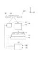
図8は、第2の実施形態に係るパターン転写装置の構成を例示する模式図である。
図8に表したように、パターン転写装置210は、基板保持装置110と、原版保持部120と、転写部130と、制御部140と、を備える。
基板保持装置110は、第1の実施形態において説明した構成を用いることができる。基板保持装置110は、ステージ115に取り付けられる。ステージ115は、基板保持装置110を任意の方向に移動させる。ステージ115は、例えば、基板保持装置110に基板5を保持させるための位置と、保持された基板5に対してパターンを転写させる位置と、の間で、基板保持装置110を移動させる。(Second Embodiment)
FIG. 8 is a schematic view illustrating the configuration of the pattern transfer apparatus according to the second embodiment.
As shown in FIG. 8, the
The
原版保持部120は、所定のパターンが形成された原版122を着脱可能に保持する。この例において、原版122には、例えば、透過型マスクが用いられる。 The original
転写部130は、原版122に形成されたパターンを基板5に転写させる。転写部130は、例えば、照明光学系131と、投影レンズ132と、を含む。照明光学系131は、原版保持部120に保持された原版122に向けて光を照射する。投影レンズ132は、原版122を透過した光を基板5に投影する。これにより、原版122に形成されているパターンが、基板5に転写される。すなわち、パターン転写装置210は、透過型の露光装置である。パターン転写装置210においては、基板保持装置110に保持された基板5の主面5aに予めフォトレジストを塗布しておく。原版122のパターンは、フォトレジストに転写される。 The
制御部140は、例えば、基板保持装置110、ステージ115及び照明光学系131に、電気的に接続される。制御部140は、例えば、基板保持装置110、ステージ115及び照明光学系131の動作を制御する。パターン転写装置210において、基板5に対するパターンの転写は、制御部140の制御によって実行される。 The
基板保持装置110において、例えば、第1垂直方向駆動部41、X軸方向駆動部43、Y軸方向駆動部44及び第2垂直方向駆動部52の駆動は、制御部140によって制御される。制御部140は、例えば、X軸方向、Y軸方向及びZ軸方向への複数の第1支持部11の先端部20の移動を、複数の第1支持部11のそれぞれについて個別に制御する。 In the
制御部140には、例えば、測定情報MIと、位置ずれ情報PIと、が入力される。制御部140は、例えば、入力された測定情報MI及び位置ずれ情報PIに基づいて、基板保持装置110を制御する。測定情報MI及び位置ずれ情報PIは、例えば、基板保持装置110に基板5を保持させる前に、制御部140に入力される。測定情報MI及び位置ずれ情報PIは、例えば、基板5毎のデータでもよいし、同じロットの基板5に共通に用いられるデータでもよい。制御部140に対する測定情報MI及び位置ずれ情報PIの入力は、例えば、ネットワークを介するものでもよいし、記録メディアを介するものでもよい。 For example, measurement information MI and positional deviation information PI are input to the
測定情報MIは、例えば、支持される前の基板5の形状に関する情報である。測定情報MIは、例えば、支持される前の基板5の形状を予め測定した測定結果を示す情報である。制御部140は、例えば、測定情報MIに対応する基板5を基板保持装置110に保持させる。制御部140は、例えば、測定情報MIを基に、複数の第2支持部12のうちの少なくともいずれかを選択的に動作させる。 The measurement information MI is information relating to the shape of the
制御部140には、例えば、基板5の形状を示す形状情報と、その基板5の形状に対して最適な第2支持部12の組み合わせを示す組み合わせ情報と、を関連付けたテーブルデータが記憶されている。制御部140は、基板保持装置110に基板5を保持させる場合に、例えば、テーブルデータに記憶された形状情報と、入力された測定情報MIと、をパターンマッチング処理によって比較する。これにより、測定情報MIに対応する基板5の形状を特定する。制御部140は、テーブルデータを参照し、特定した形状に関連付けられた組み合わせ情報を読み出す。制御部140は、複数の第2支持部12の中から、組み合わせ情報に対応する第2支持部12を駆動する。 The
このように、制御部140は、例えば、組み合わせ情報を基に、基板5の形状に適した組み合わせの第2支持部12に基板5を支持させる。例えば、中心付近において上向きに突出するように歪んだ基板5である場合には、前述のように、第2グループ12bの第2支持部12に基板5を支持させる。これにより、複数の第1支持部10に支持された時点における基板5の歪みを小さくすることができる。 Thus, the
制御部140は、例えば、第2垂直方向駆動部52を駆動させて第2支持部12の可動部51を第2位置から第1位置に移動させ、基板5を複数の第1支持部11に支持させる。制御部140は、例えば、測定情報MIを基に、複数の第1支持部11のそれぞれの先端部20の主面10aからの高さ及びX−Y平面に沿う方向の位置を調整する。制御部140は、例えば、調整により、基板5の歪みを小さくする。これにより、例えば、転写部130で基板5にパターンを転写させる場合に、基板5の歪みに起因する重ね合わせ精度の低下が抑えられる。なお、制御部140は、基板保持装置110の制御に関する部分において、基板保持装置110に設けてもよい。 For example, the
図9(a)及び図9(b)は、第2の実施形態に係るパターン転写装置の特性を例示する模式図である。
図9(a)に表したように、転写部130によって新たに転写させる転写パターンTPは、基板5の歪みを抑えても、例えば、投影レンズ132のディストーションにより、基板5に既に形成されている既存パターンEPとずれる。すなわち、重ね合わせ精度は、基板5の歪みだけでなく、例えば、投影レンズ132のディストーションにも起因する。FIG. 9A and FIG. 9B are schematic views illustrating characteristics of the pattern transfer apparatus according to the second embodiment.
As shown in FIG. 9A, the transfer pattern TP newly transferred by the
位置ずれ情報PIは、例えば、既存パターンEPと、転写部TPとの、相対的な位置ずれに関する情報である。位置ずれ情報PIは、例えば、投影レンズ132の光学特性データと、既存パターンEPの情報と、を基に、算出される。制御部140は、例えば、位置ずれ情報PIを基に、複数の第1支持部11のそれぞれの先端部20の主面10aからの高さ及びX−Y平面に沿う方向の位置を調整する。 The positional deviation information PI is, for example, information regarding the relative positional deviation between the existing pattern EP and the transfer portion TP. The positional deviation information PI is calculated based on, for example, optical characteristic data of the
図9(b)に表したように、制御部140は、例えば、既存パターンEPと転写部TPとの相対的な位置ずれが少なくなるように、複数の第1支持部11のそれぞれの先端部20の高さ及び位置を調整する。これにより、例えば、投影レンズ132のディストーションに起因する重ね合わせ精度の低下も抑えられる。 As shown in FIG. 9B, the
制御部140に入力される情報は、測定情報MIと位置ずれ情報PIとの一方のみでもよい。制御部140は、測定情報MIのみで先端部20の調整を行ってもよい。制御部140は、位置ずれ情報PIのみで先端部20の調整を行ってもよい。制御部140は、測定情報MIと位置ずれ情報PIとの双方を用いて、先端部20の調整を行ってもよい。 Only one of the measurement information MI and the positional deviation information PI may be input to the
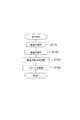
図10は、第2の実施形態に係るパターン転写装置のパターン転写方法を例示するフローチャートである。
図10に表したように、実施形態に係るパターン転写装置210のパターン転写方法は、基板保持装置110に基板5を保持させるステップS110と、原版保持部120に原版122を保持させるステップS120と、複数の第1支持部11の先端部20の移動を複数の第1支持部11のそれぞれについて個別に制御し、基板5の歪みを調整するステップS130と、原版122のパターンを基板5に転写させるステップS140と、を含む。ステップS110〜ステップS130は、技術的に可能な範囲で入れ替えることができる。FIG. 10 is a flowchart illustrating the pattern transfer method of the pattern transfer apparatus according to the second embodiment.
As shown in FIG. 10, the pattern transfer method of the
ステップS110では、例えば、測定情報MIを基に、基板5の形状に適した組み合わせの第2支持部12に基板5を支持させる処理と、第2垂直方向駆動部52を駆動させて第2支持部12の可動部51を第2位置から第1位置に移動させ、基板5を複数の第1支持部11に支持させる処理と、を実施する。 In step S110, for example, based on the measurement information MI, the
ステップS130では、例えば、測定情報MIを基に、複数の第1支持部11のそれぞれの先端部20の主面10aからの高さ及びX−Y平面に沿う方向の位置を調整する処理を実施する。ステップS130では、例えば、位置ずれ情報PIを基に、複数の第1支持部11のそれぞれの先端部20の主面10aからの高さ及びX−Y平面に沿う方向の位置を調整する処理を実施する。 In step S130, for example, based on the measurement information MI, a process of adjusting the height from the
これにより、パターン転写装置210のパターン転写方法において、保持された基板5の歪みが、適切に調整される。また、パターン転写装置210のパターン転写方法において、重ね合わせ精度の低下が抑制される。 Thereby, in the pattern transfer method of the
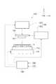
図11は、第2の実施形態に係る別のパターン転写装置の構成を例示する模式図である。
図11に表したように、パターン転写装置220の原版122には、例えば、反射型マスクが用いられる。
照明光学系131は、原版保持部120に保持された原版122に向けて光を照射する。投影レンズ132は、原版122を反射した光を基板5に投影する。これにより、原版122に形成されているパターンが、基板5に転写される。すなわち、パターン転写装置220は、反射型の露光装置である。FIG. 11 is a schematic view illustrating the configuration of another pattern transfer apparatus according to the second embodiment.
As shown in FIG. 11, for example, a reflective mask is used for the
The illumination
パターン転写装置220においても、複数の第1支持部11のそれぞれの先端部20の主面10aからの高さ及びX−Y平面に沿う方向の位置を調整することで、保持された基板5の歪みが、適切に調整される。また、重ね合わせ精度の低下が抑制される。 Also in the
図12は、第2の実施形態に係る別のパターン転写装置の構成を例示する模式図である。
図12に表したように、パターン転写装置230の原版122には、例えば、インプリントテンプレートが用いられる。
転写部130は、光源133と、テンプレート駆動部134と、を含む。光源133は、例えば、原版122に向けて紫外光を照射する。テンプレート駆動部134は、例えば、原版保持部120をZ軸方向に移動させ、原版保持部120に保持された原版122を基板5に接触させる。FIG. 12 is a schematic view illustrating the configuration of another pattern transfer apparatus according to the second embodiment.
As shown in FIG. 12, for example, an imprint template is used for the
The
パターン転写装置230においては、例えば、基板保持装置110に保持された基板5の主面5aに、紫外線硬化型の樹脂を塗布する。テンプレート駆動部134を駆動させ、樹脂が塗布された基板5の主面5aに、原版122を接触させる。光源133から紫外光を照射し、原版保持部120及び原版122を透過した紫外光によって、樹脂を硬化させる。これにより、原版122に形成された凹凸状のパターンが、基板5に転写される。すなわち、パターン転写装置230は、インプリント装置である。 In the
パターン転写装置230においても、複数の第1支持部11のそれぞれの先端部20の主面10aからの高さ及びX−Y平面に沿う方向の位置を調整することで、保持された基板5の歪みが、適切に調整される。また、重ね合わせ精度の低下が抑制される。 Also in the
実施形態によれば、保持された基板の歪みを適切に調整できる基板保持装置及びパターン転写装置並びにパターン転写方法が提供される。 According to the embodiment, a substrate holding device, a pattern transfer device, and a pattern transfer method capable of appropriately adjusting the distortion of the held substrate are provided.
なお、本願明細書において、「垂直」及び「平行」は、厳密な垂直及び厳密な平行だけではなく、例えば製造工程におけるばらつきなどを含むものであり、実質的に垂直及び実質的に平行であれは良い。 In the present specification, “vertical” and “parallel” include not only strictly vertical and strictly parallel, but also include, for example, variations in the manufacturing process, and may be substantially vertical and substantially parallel. is good.
以上、具体例を参照しつつ、本発明の実施の形態について説明した。しかし、本発明の実施形態は、これらの具体例に限定されるものではない。例えば、基板保持装置及びパターン転写装置に含まれる、本体部、第1支持部、吸着部、第2支持部、第3支持部、弾性体、第1計測部、第2計測部、原版保持部、転写部及び制御部などの各要素の具体的な構成に関しては、当業者が公知の範囲から適宜選択することにより本発明を同様に実施し、同様の効果を得ることができる限り、本発明の範囲に包含される。
また、各具体例のいずれか2つ以上の要素を技術的に可能な範囲で組み合わせたものも、本発明の要旨を包含する限り本発明の範囲に含まれる。The embodiments of the present invention have been described above with reference to specific examples. However, embodiments of the present invention are not limited to these specific examples. For example, a main body part, a first support part, an adsorption part, a second support part, a third support part, an elastic body, a first measurement part, a second measurement part, and an original plate holding part, which are included in the substrate holding device and the pattern transfer device As for the specific configuration of each element such as the transfer section and the control section, the present invention can be implemented in the same manner by appropriately selecting from a well-known range by those skilled in the art, as long as the same effects can be obtained. It is included in the range.
Moreover, what combined any two or more elements of each specific example in the technically possible range is also included in the scope of the present invention as long as the gist of the present invention is included.
その他、本発明の実施の形態として上述した基板保持装置及びパターン転写装置並びにパターン転写方法を基にして、当業者が適宜設計変更して実施し得る全ての基板保持装置及びパターン転写装置並びにパターン転写方法も、本発明の要旨を包含する限り、本発明の範囲に属する。 In addition, based on the substrate holding device, the pattern transfer device, and the pattern transfer method described above as the embodiments of the present invention, all substrate holding devices, pattern transfer devices, and pattern transfers that can be implemented by those skilled in the art as appropriate. The method also belongs to the scope of the present invention as long as it includes the gist of the present invention.
その他、本発明の思想の範疇において、当業者であれば、各種の変更例及び修正例に想到し得るものであり、それら変更例及び修正例についても本発明の範囲に属するものと了解される。 In addition, in the category of the idea of the present invention, those skilled in the art can conceive of various changes and modifications, and it is understood that these changes and modifications also belong to the scope of the present invention. .
本発明のいくつかの実施形態を説明したが、これらの実施形態は、例として提示したものであり、発明の範囲を限定することは意図していない。これら新規な実施形態は、その他の様々な形態で実施されることが可能であり、発明の要旨を逸脱しない範囲で、種々の省略、置き換え、変更を行うことができる。これら実施形態やその変形は、発明の範囲や要旨に含まれるとともに、特許請求の範囲に記載された発明とその均等の範囲に含まれる。 Although several embodiments of the present invention have been described, these embodiments are presented by way of example and are not intended to limit the scope of the invention. These novel embodiments can be implemented in various other forms, and various omissions, replacements, and changes can be made without departing from the scope of the invention. These embodiments and modifications thereof are included in the scope and gist of the invention, and are included in the invention described in the claims and the equivalents thereof.
5…基板、 5a…主面、 5e…外周部、 6…ポンプ、 10…本体部、 10a…主面、 10b…排気管路、 10c…開口、 11…第1支持部、 12…第2支持部、 12a…第1グループ、 12b…第2グループ、 13…第3支持部、 14…弾性体、 14a…先端、 20…先端部、 20a…吸引口、 20b…先端面、 21…吸引管路、 22…吸着部、 31…第1筒部、 31a…突出部、 32…第2筒部、 32a…突出部、 41…第1垂直方向駆動部、 41a…先端、 42…平行方向駆動部、 43…X軸方向駆動部、 44…Y軸方向駆動部、 51…可動部、 51a…端、 52…第2垂直方向駆動部、 61…第1計測部、 61a…発光部、 61b…受光部、 62…第2計測部、 63…X軸方向計測部、 64…Y軸方向計測部、 110、112…基板保持装置、 115…ステージ、 120…原版保持部、 122…原版、 130…転写部、 131…照明光学系、 132…投影レンズ、 133…光源、 134…テンプレート駆動部、 140…制御部、 210、220、230…パターン転写装置 PI…位置ずれ情報、 MI…測定情報、 EP…既存パターン、 TP…転写パターン DESCRIPTION OF
Claims (11)
Translated fromJapanese前記主面上に配置され、それぞれ独立して移動可能な複数の第1支持部であって、前記複数の第1支持部のそれぞれは、第1パターンが転写される基板を吸着可能な吸着部と、
前記主面に対して垂直な第1方向に前記吸着部を移動させる垂直方向駆動部と、前記主面に対して平行な第2方向に前記吸着部を移動させる平行方向駆動部と、を有し、前記吸着部は、転写される前記第1パターンに応じて、独立して前記第1方向及び前記第2方向に移動可能である複数の第1支持部と、
を備えた基板保持装置。A plate-like main body having a main surface;
A plurality of first support portions arranged on the main surface and independently movable, wherein each of the plurality of first support portions can suck a substrate onto which a first pattern is transferred. When,
A vertical driving unit that moves the suction unit in a first direction perpendicular to the main surface; and a parallel driving unit that moves the suction unit in a second direction parallel to the main surface. A plurality of first support portions that are independently movable in the first direction and the second direction according to the first pattern to be transferred;
A substrate holding device.
前記吸着部は、前記主面からみた前記第1方向に沿う高さが低い第1状態と、前記主面からみた前記第1方向に沿う高さが前記第1状態よりも高い第2状態と、の間で、前記第1方向に沿って移動可能であり、
前記第1状態の前記吸着部の位置から前記第2状態の前記吸着部の位置に向かう方向の、前記複数の第2支持部の端は、前記主面からみた前記第1方向に沿う高さが前記第1状態の前記高さよりも低い第3状態と、前記主面からみた前記第1方向に沿う高さが前記第2状態の前記高さよりも高い第4状態と、を有する請求項1記載の基板保持装置。A plurality of second support portions arranged on the main surface and movable along the first direction;
The suction portion includes a first state having a low height along the first direction viewed from the main surface, and a second state having a height along the first direction viewed from the main surface higher than the first state. , And can be moved along the first direction,
The ends of the plurality of second support portions in the direction from the position of the suction portion in the first state toward the position of the suction portion in the second state are heights along the first direction as viewed from the main surface. 2. A third state in which the height is lower than the height in thefirst state, and a fourth state in which the height along the first direction viewed from the main surface is higher than the height in the second state. The board | substrate holding apparatus of description.
主面を有する板状の本体部と、
前記主面上に配置され、それぞれ独立して移動可能な複数の第1支持部であって、前記複数の第1支持部のそれぞれは、前記第1パターンが転写される基板を吸着可能な吸着部と、前記主面に対して垂直な第1方向に前記吸着部を移動させる垂直方向駆動部と、前記主面に対して平行な第2方向に前記吸着部を移動させる平行方向駆動部と、を有し、転写される前記第1パターンに応じて、独立して前記第1方向及び前記第2方向に移動可能である前記複数の第1支持部と、
を含む基板保持装置と、
前記複数の第1支持部のそれぞれの、前記第1方向及び前記第2方向への前記吸着部の移動を制御する制御部と、
前記第1パターンを前記基板に転写させる転写部と、
を備えたパターン転写装置。An original holding unit for detachably holding the original on which the first pattern is formed;
A plate-like main body having a main surface;
A plurality of first support portions arranged on the main surface and independently movable, wherein each of the plurality of first support portions is capable of sucking a substrate onto which the first pattern is transferred. A vertical direction drive unit that moves the suction unit in a first direction perpendicular to the main surface, and a parallel direction drive unit that moves the suction unit in a second direction parallel to the main surface The plurality of first support portions independently movable in the first direction and the second direction according to the first pattern to be transferred,
A substrate holding device including:
A control unit that controls movement of the suction unit in the first direction and the second direction of each of the plurality of first support units;
A transfer portion for transferring the first pattern to the substrate;
A pattern transfer apparatus.
前記吸着部は、前記主面からみた前記第1方向に沿う高さが低い第1状態と、前記主面からみた前記第1方向に沿う高さが前記第1状態よりも高い第2状態と、の間で、前記第1方向に沿って移動可能であり、
前記第1状態の前記吸着部の位置から前記第2状態の前記吸着部の位置に向かう方向の、前記複数の第2支持部の端は、前記主面からみた前記第1方向に沿う高さが前記第1状態の前記高さよりも低い第3状態と、前記主面からみた前記第1方向に沿う高さが前記第2状態の前記高さよりも高い第4状態と、を有し、
前記制御部は、支持される前の前記基板の形状を予め測定した測定情報を基に、前記複数の第2支持部のうちの少なくともいずれかを選択的に動作させる請求項7に記載のパターン転写装置。The substrate holding device further includes a plurality of second support portions arranged on the main surface and movable along the first direction,
The suction portion includes a first state having a low height along the first direction viewed from the main surface, and a second state having a height along the first direction viewed from the main surface higher than the first state. , And can be moved along the first direction,
The ends of the plurality of second support portions in the direction from the position of the suction portion in the first state toward the position of the suction portion in the second state are heights along the first direction as viewed from the main surface. A third state that is lower than the height of thefirst state, and a fourth state in which the height along the first direction viewed from the main surface is higher than the height of the second state,
The pattern according to claim 7, wherein the control unit selectively operates at least one of the plurality of second support units based on measurement information obtained by measuring in advance the shape of the substrate before being supported. Transfer device.
前記複数の第1支持部のそれぞれの前記吸着部の前記主面からの高さ及び前記第2方向の位置を調整する請求項7〜9のいずれか1つに記載のパターン転写装置。The control unit is based on misalignment information regarding a relative misalignment between the second pattern already formed on the substrate and the first pattern newly transferred by the transfer unit.
10. The pattern transfer device according to claim 7, wherein a height of the suction portion of each of the plurality of first support portions from the main surface and a position in the second direction are adjusted.
前記基板保持装置に前記基板を保持させる工程と、
前記原版保持部に前記原版を保持させる工程と、
前記複数の第1支持部のそれぞれの、前記第1方向及び前記第2方向への前記吸着部の移動を制御し、前記基板の歪みを調整する工程と、
前記パターンを前記基板に転写させる工程と、
を備えたパターン転写方法。A pattern transfer method using the pattern transfer apparatus according to any one of claims 7 to 10,
Holding the substrate on the substrate holding device;
Holding the original in the original holding unit;
Controlling the movement of the suction portion in each of the first direction and the second direction of each of the plurality of first support portions, and adjusting distortion of the substrate;
Transferring the pattern to the substrate;
A pattern transfer method comprising:
Priority Applications (2)
| Application Number | Priority Date | Filing Date | Title |
|---|---|---|---|
| JP2012039074AJP5912654B2 (en) | 2012-02-24 | 2012-02-24 | Substrate holding device, pattern transfer device, and pattern transfer method |
| US13/600,123US9188879B2 (en) | 2012-02-24 | 2012-08-30 | Substrate holding apparatus, pattern transfer apparatus, and pattern transfer method |
Applications Claiming Priority (1)
| Application Number | Priority Date | Filing Date | Title |
|---|---|---|---|
| JP2012039074AJP5912654B2 (en) | 2012-02-24 | 2012-02-24 | Substrate holding device, pattern transfer device, and pattern transfer method |
Related Child Applications (1)
| Application Number | Title | Priority Date | Filing Date |
|---|---|---|---|
| JP2014254616ADivisionJP5865475B2 (en) | 2014-12-16 | 2014-12-16 | Substrate holding device, pattern transfer device, and pattern transfer method |
Publications (2)
| Publication Number | Publication Date |
|---|---|
| JP2013175595A JP2013175595A (en) | 2013-09-05 |
| JP5912654B2true JP5912654B2 (en) | 2016-04-27 |
Family
ID=49002547
Family Applications (1)
| Application Number | Title | Priority Date | Filing Date |
|---|---|---|---|
| JP2012039074AActiveJP5912654B2 (en) | 2012-02-24 | 2012-02-24 | Substrate holding device, pattern transfer device, and pattern transfer method |
Country Status (2)
| Country | Link |
|---|---|
| US (1) | US9188879B2 (en) |
| JP (1) | JP5912654B2 (en) |
Families Citing this family (4)
| Publication number | Priority date | Publication date | Assignee | Title |
|---|---|---|---|---|
| NL2017433A (en) | 2015-10-09 | 2017-04-11 | Asml Netherlands Bv | Substrate table and lithographic apparatus |
| KR102493253B1 (en) | 2018-04-26 | 2023-01-27 | 에이에스엠엘 네델란즈 비.브이. | Stage apparatus, lithographic apparatus, control unit and method |
| EP3385792A3 (en) | 2018-04-26 | 2018-12-26 | ASML Netherlands B.V. | Stage apparatus for use in a lithographic apparatus |
| CN113467196B (en)* | 2021-07-30 | 2025-06-13 | 迪盛微(江苏)装备科技有限公司 | Work platform and lithography equipment |
Family Cites Families (15)
| Publication number | Priority date | Publication date | Assignee | Title |
|---|---|---|---|---|
| EP0456426B1 (en) | 1990-05-07 | 2004-09-15 | Canon Kabushiki Kaisha | Vacuum type wafer holder |
| US5094536A (en) | 1990-11-05 | 1992-03-10 | Litel Instruments | Deformable wafer chuck |
| JPH05190414A (en)* | 1992-01-17 | 1993-07-30 | Nikon Corp | Substrate suction apparatus |
| JPH06169007A (en)* | 1992-11-27 | 1994-06-14 | Mitsubishi Electric Corp | Semiconductor manufacturing equipment |
| JPH10150097A (en) | 1996-11-21 | 1998-06-02 | Dainippon Screen Mfg Co Ltd | Spin chuck for board processor |
| US6556281B1 (en)* | 2000-05-23 | 2003-04-29 | Asml Us, Inc. | Flexible piezoelectric chuck and method of using the same |
| JPWO2003052804A1 (en) | 2001-12-17 | 2005-04-28 | 株式会社ニコン | Substrate holding apparatus, exposure apparatus and device manufacturing method |
| DE102004013886A1 (en)* | 2004-03-16 | 2005-10-06 | Carl Zeiss Smt Ag | Multiple Exposure Method, Microlithography Projection Exposure System and Projection System |
| JP2005277117A (en) | 2004-03-25 | 2005-10-06 | Nikon Corp | Substrate holding apparatus, exposure method and apparatus, and device manufacturing method |
| JP2007080935A (en)* | 2005-09-12 | 2007-03-29 | Dainippon Screen Mfg Co Ltd | Substrate heat treatment apparatus |
| JP2007123560A (en) | 2005-10-28 | 2007-05-17 | Toshiba Corp | Wafer chuck and semiconductor manufacturing method |
| JP2007311374A (en)* | 2006-05-16 | 2007-11-29 | Nikon Corp | Substrate holder, exposure apparatus, and device manufacturing method |
| JP4837642B2 (en)* | 2007-09-26 | 2011-12-14 | 東京エレクトロン株式会社 | Substrate transport position alignment method, substrate processing system, and computer-readable storage medium |
| JP4985392B2 (en) | 2007-12-28 | 2012-07-25 | 株式会社ニコン | Substrate holding apparatus, exposure apparatus, and device manufacturing method |
| JP2009168860A (en)* | 2008-01-10 | 2009-07-30 | Olympus Corp | Stage device for substrate |
- 2012
- 2012-02-24JPJP2012039074Apatent/JP5912654B2/enactiveActive
- 2012-08-30USUS13/600,123patent/US9188879B2/enactiveActive
Also Published As
| Publication number | Publication date |
|---|---|
| US20130222782A1 (en) | 2013-08-29 |
| JP2013175595A (en) | 2013-09-05 |
| US9188879B2 (en) | 2015-11-17 |
Similar Documents
| Publication | Publication Date | Title |
|---|---|---|
| US11097426B2 (en) | Carrier system, exposure apparatus, carrier method, exposure method, device manufacturing method, and suction device | |
| CN105830208B (en) | Substrate holding device, exposure device, and device manufacturing method | |
| JP6638774B2 (en) | Exposure method and exposure apparatus, device manufacturing method, and flat panel display manufacturing method | |
| KR101625706B1 (en) | Imprint apparatus, manufacturing method for article using the same, and imprint method | |
| KR101911724B1 (en) | Movable body apparatus, object processing device, exposure apparatus, flat-panel display manufacturing method, and device manufacturing method | |
| KR20130114129A (en) | Movable body apparatus, object processing device, exposure apparatus, flat-panel display manufacturing method, and device manufacturing method | |
| JP2021140172A (en) | Exposure equipment, exposure methods, flat panel display manufacturing methods, and device manufacturing methods | |
| JP5912654B2 (en) | Substrate holding device, pattern transfer device, and pattern transfer method | |
| JP5682106B2 (en) | Substrate processing method and substrate processing apparatus | |
| JP5865475B2 (en) | Substrate holding device, pattern transfer device, and pattern transfer method | |
| JP2012160635A (en) | Retainer, imprint apparatus using it and method of manufacturing article | |
| US9746787B2 (en) | Holding apparatus, exposure apparatus and manufacturing method of device | |
| US11243476B2 (en) | Stage apparatus, lithographic apparatus, control unit and method | |
| CN102955373B (en) | Approaching exposure apparatus and approaching type exposure method | |
| JP2017112230A (en) | Imprint apparatus and article manufacturing method | |
| JP2019010691A (en) | Hand of industrial robot and industrial robot | |
| WO2017057589A1 (en) | Mobile object device, exposure device, method for manufacturing flat panel display, method for manufacturing device, and method for moving object | |
| JP2013054343A (en) | Proximity exposure device and proximity exposure method | |
| JP2015079812A (en) | Substrate holding device and exposure apparatus | |
| JP2013106007A (en) | Stage device, exposure equipment and device manufacturing method | |
| WO2018181476A1 (en) | Exposure device, exposure method, production method for flat panel display, and device production method | |
| JP2011165744A (en) | Optical member deforming apparatus, optical system, exposure apparatus, and method of manufacturing device | |
| JPWO2017057471A1 (en) | Exposure apparatus, flat panel display manufacturing method, device manufacturing method, and exposure method |
Legal Events
| Date | Code | Title | Description |
|---|---|---|---|
| A621 | Written request for application examination | Free format text:JAPANESE INTERMEDIATE CODE: A621 Effective date:20140212 | |
| A977 | Report on retrieval | Free format text:JAPANESE INTERMEDIATE CODE: A971007 Effective date:20140618 | |
| A131 | Notification of reasons for refusal | Free format text:JAPANESE INTERMEDIATE CODE: A131 Effective date:20140624 | |
| A521 | Written amendment | Free format text:JAPANESE INTERMEDIATE CODE: A523 Effective date:20140825 | |
| A02 | Decision of refusal | Free format text:JAPANESE INTERMEDIATE CODE: A02 Effective date:20140918 | |
| A521 | Written amendment | Free format text:JAPANESE INTERMEDIATE CODE: A523 Effective date:20141216 | |
| A911 | Transfer of reconsideration by examiner before appeal (zenchi) | Free format text:JAPANESE INTERMEDIATE CODE: A911 Effective date:20141224 | |
| RD02 | Notification of acceptance of power of attorney | Free format text:JAPANESE INTERMEDIATE CODE: A7422 Effective date:20150216 | |
| RD04 | Notification of resignation of power of attorney | Free format text:JAPANESE INTERMEDIATE CODE: A7424 Effective date:20150218 | |
| A912 | Removal of reconsideration by examiner before appeal (zenchi) | Free format text:JAPANESE INTERMEDIATE CODE: A912 Effective date:20150306 | |
| A521 | Written amendment | Free format text:JAPANESE INTERMEDIATE CODE: A523 Effective date:20151102 | |
| A521 | Written amendment | Free format text:JAPANESE INTERMEDIATE CODE: A523 Effective date:20160126 | |
| A61 | First payment of annual fees (during grant procedure) | Free format text:JAPANESE INTERMEDIATE CODE: A61 Effective date:20160401 | |
| R151 | Written notification of patent or utility model registration | Ref document number:5912654 Country of ref document:JP Free format text:JAPANESE INTERMEDIATE CODE: R151 | |
| S111 | Request for change of ownership or part of ownership | Free format text:JAPANESE INTERMEDIATE CODE: R313111 | |
| R350 | Written notification of registration of transfer | Free format text:JAPANESE INTERMEDIATE CODE: R350 | |
| S111 | Request for change of ownership or part of ownership | Free format text:JAPANESE INTERMEDIATE CODE: R313111 | |
| R350 | Written notification of registration of transfer | Free format text:JAPANESE INTERMEDIATE CODE: R350 |