JP5912287B2 - Laser processing method and laser processing apparatus - Google Patents
Laser processing method and laser processing apparatusDownload PDFInfo
- Publication number
- JP5912287B2 JP5912287B2JP2011112484AJP2011112484AJP5912287B2JP 5912287 B2JP5912287 B2JP 5912287B2JP 2011112484 AJP2011112484 AJP 2011112484AJP 2011112484 AJP2011112484 AJP 2011112484AJP 5912287 B2JP5912287 B2JP 5912287B2
- Authority
- JP
- Japan
- Prior art keywords
- laser beam
- pulse laser
- pulse
- workpiece
- laser processing
- Prior art date
- Legal status (The legal status is an assumption and is not a legal conclusion. Google has not performed a legal analysis and makes no representation as to the accuracy of the status listed.)
- Active
Links
Images


Classifications
- B—PERFORMING OPERATIONS; TRANSPORTING
- B23—MACHINE TOOLS; METAL-WORKING NOT OTHERWISE PROVIDED FOR
- B23K—SOLDERING OR UNSOLDERING; WELDING; CLADDING OR PLATING BY SOLDERING OR WELDING; CUTTING BY APPLYING HEAT LOCALLY, e.g. FLAME CUTTING; WORKING BY LASER BEAM
- B23K26/00—Working by laser beam, e.g. welding, cutting or boring
- B23K26/352—Working by laser beam, e.g. welding, cutting or boring for surface treatment
- B23K26/3568—Modifying rugosity
- B23K26/3584—Increasing rugosity, e.g. roughening
- B—PERFORMING OPERATIONS; TRANSPORTING
- B23—MACHINE TOOLS; METAL-WORKING NOT OTHERWISE PROVIDED FOR
- B23K—SOLDERING OR UNSOLDERING; WELDING; CLADDING OR PLATING BY SOLDERING OR WELDING; CUTTING BY APPLYING HEAT LOCALLY, e.g. FLAME CUTTING; WORKING BY LASER BEAM
- B23K26/00—Working by laser beam, e.g. welding, cutting or boring
- B23K26/02—Positioning or observing the workpiece, e.g. with respect to the point of impact; Aligning, aiming or focusing the laser beam
- B23K26/06—Shaping the laser beam, e.g. by masks or multi-focusing
- B23K26/0604—Shaping the laser beam, e.g. by masks or multi-focusing by a combination of beams
- B23K26/0613—Shaping the laser beam, e.g. by masks or multi-focusing by a combination of beams having a common axis
- B—PERFORMING OPERATIONS; TRANSPORTING
- B23—MACHINE TOOLS; METAL-WORKING NOT OTHERWISE PROVIDED FOR
- B23K—SOLDERING OR UNSOLDERING; WELDING; CLADDING OR PLATING BY SOLDERING OR WELDING; CUTTING BY APPLYING HEAT LOCALLY, e.g. FLAME CUTTING; WORKING BY LASER BEAM
- B23K26/00—Working by laser beam, e.g. welding, cutting or boring
- B23K26/02—Positioning or observing the workpiece, e.g. with respect to the point of impact; Aligning, aiming or focusing the laser beam
- B23K26/06—Shaping the laser beam, e.g. by masks or multi-focusing
- B23K26/062—Shaping the laser beam, e.g. by masks or multi-focusing by direct control of the laser beam
- B23K26/0622—Shaping the laser beam, e.g. by masks or multi-focusing by direct control of the laser beam by shaping pulses
- B—PERFORMING OPERATIONS; TRANSPORTING
- B23—MACHINE TOOLS; METAL-WORKING NOT OTHERWISE PROVIDED FOR
- B23K—SOLDERING OR UNSOLDERING; WELDING; CLADDING OR PLATING BY SOLDERING OR WELDING; CUTTING BY APPLYING HEAT LOCALLY, e.g. FLAME CUTTING; WORKING BY LASER BEAM
- B23K26/00—Working by laser beam, e.g. welding, cutting or boring
- B23K26/02—Positioning or observing the workpiece, e.g. with respect to the point of impact; Aligning, aiming or focusing the laser beam
- B23K26/06—Shaping the laser beam, e.g. by masks or multi-focusing
- B23K26/064—Shaping the laser beam, e.g. by masks or multi-focusing by means of optical elements, e.g. lenses, mirrors or prisms
- B23K26/0648—Shaping the laser beam, e.g. by masks or multi-focusing by means of optical elements, e.g. lenses, mirrors or prisms comprising lenses
- B—PERFORMING OPERATIONS; TRANSPORTING
- B23—MACHINE TOOLS; METAL-WORKING NOT OTHERWISE PROVIDED FOR
- B23K—SOLDERING OR UNSOLDERING; WELDING; CLADDING OR PLATING BY SOLDERING OR WELDING; CUTTING BY APPLYING HEAT LOCALLY, e.g. FLAME CUTTING; WORKING BY LASER BEAM
- B23K26/00—Working by laser beam, e.g. welding, cutting or boring
- B23K26/08—Devices involving relative movement between laser beam and workpiece
- B23K26/083—Devices involving movement of the workpiece in at least one axial direction
- B23K26/0853—Devices involving movement of the workpiece in at least in two axial directions, e.g. in a plane
- B—PERFORMING OPERATIONS; TRANSPORTING
- B23—MACHINE TOOLS; METAL-WORKING NOT OTHERWISE PROVIDED FOR
- B23K—SOLDERING OR UNSOLDERING; WELDING; CLADDING OR PLATING BY SOLDERING OR WELDING; CUTTING BY APPLYING HEAT LOCALLY, e.g. FLAME CUTTING; WORKING BY LASER BEAM
- B23K26/00—Working by laser beam, e.g. welding, cutting or boring
- B23K26/36—Removing material
- B23K26/362—Laser etching
- B23K26/364—Laser etching for making a groove or trench, e.g. for scribing a break initiation groove
- B—PERFORMING OPERATIONS; TRANSPORTING
- B23—MACHINE TOOLS; METAL-WORKING NOT OTHERWISE PROVIDED FOR
- B23K—SOLDERING OR UNSOLDERING; WELDING; CLADDING OR PLATING BY SOLDERING OR WELDING; CUTTING BY APPLYING HEAT LOCALLY, e.g. FLAME CUTTING; WORKING BY LASER BEAM
- B23K26/00—Working by laser beam, e.g. welding, cutting or boring
- B23K26/36—Removing material
- B23K26/40—Removing material taking account of the properties of the material involved
- B23K26/402—Removing material taking account of the properties of the material involved involving non-metallic material, e.g. isolators
- B—PERFORMING OPERATIONS; TRANSPORTING
- B23—MACHINE TOOLS; METAL-WORKING NOT OTHERWISE PROVIDED FOR
- B23K—SOLDERING OR UNSOLDERING; WELDING; CLADDING OR PLATING BY SOLDERING OR WELDING; CUTTING BY APPLYING HEAT LOCALLY, e.g. FLAME CUTTING; WORKING BY LASER BEAM
- B23K26/00—Working by laser beam, e.g. welding, cutting or boring
- B23K26/60—Preliminary treatment
- B—PERFORMING OPERATIONS; TRANSPORTING
- B23—MACHINE TOOLS; METAL-WORKING NOT OTHERWISE PROVIDED FOR
- B23K—SOLDERING OR UNSOLDERING; WELDING; CLADDING OR PLATING BY SOLDERING OR WELDING; CUTTING BY APPLYING HEAT LOCALLY, e.g. FLAME CUTTING; WORKING BY LASER BEAM
- B23K2101/00—Articles made by soldering, welding or cutting
- B23K2101/36—Electric or electronic devices
- B23K2101/40—Semiconductor devices
- B—PERFORMING OPERATIONS; TRANSPORTING
- B23—MACHINE TOOLS; METAL-WORKING NOT OTHERWISE PROVIDED FOR
- B23K—SOLDERING OR UNSOLDERING; WELDING; CLADDING OR PLATING BY SOLDERING OR WELDING; CUTTING BY APPLYING HEAT LOCALLY, e.g. FLAME CUTTING; WORKING BY LASER BEAM
- B23K2103/00—Materials to be soldered, welded or cut
- B23K2103/50—Inorganic material, e.g. metals, not provided for in B23K2103/02 – B23K2103/26
- H—ELECTRICITY
- H10—SEMICONDUCTOR DEVICES; ELECTRIC SOLID-STATE DEVICES NOT OTHERWISE PROVIDED FOR
- H10H—INORGANIC LIGHT-EMITTING SEMICONDUCTOR DEVICES HAVING POTENTIAL BARRIERS
- H10H20/00—Individual inorganic light-emitting semiconductor devices having potential barriers, e.g. light-emitting diodes [LED]
- H10H20/01—Manufacture or treatment
Landscapes
- Physics & Mathematics (AREA)
- Optics & Photonics (AREA)
- Engineering & Computer Science (AREA)
- Plasma & Fusion (AREA)
- Mechanical Engineering (AREA)
- Laser Beam Processing (AREA)
- Dicing (AREA)
Description
Translated fromJapanese本発明は、透明部材からなる被加工物にパルスレーザー光線を照射してレーザー加工を施すレーザー加工方法およびレーザー加工装置に関する。 The present invention relates to a laser processing method and a laser processing apparatus for performing laser processing by irradiating a workpiece made of a transparent member with a pulsed laser beam.
半導体デバイス製造工程においては、略円板形状であるシリコン基板の表面に格子状に配列されたストリートと呼ばれる分割予定ラインによって複数の領域が区画され、この区画された領域にIC、LSI等の回路を形成する。そして、半導体ウエーハをストリートに沿って切断することにより回路が形成された領域を分割して個々の半導体チップを製造している。また、サファイア基板、酸化珪素基板、二酸化珪素基板、リチウムタンタレート基板、リチウムナイオベート基板の表面に窒化ガリウム系化合物半導体等が積層された光デバイスウエーハもストリートに沿って切断することにより個々の発光ダイオード、レーザーダイオード等の光デバイスに分割され、電気機器に広く利用されている。 In the semiconductor device manufacturing process, a plurality of regions are defined by dividing lines called streets arranged in a lattice pattern on the surface of a substantially disk-shaped silicon substrate, and circuits such as IC and LSI are defined in the partitioned regions. Form. Then, the semiconductor wafer is cut along the streets to divide the region where the circuit is formed to manufacture individual semiconductor chips. In addition, an optical device wafer in which a gallium nitride compound semiconductor or the like is laminated on the surface of a sapphire substrate, silicon oxide substrate, silicon dioxide substrate, lithium tantalate substrate, or lithium niobate substrate is cut along the street to emit individual light. Divided into optical devices such as diodes and laser diodes, they are widely used in electrical equipment.
近年、半導体ウエーハ等のウエーハをストリートに沿って分割する方法として、ウエーハに形成されたストリートに沿ってウエーハに対して吸収性を有する波長(例えば532nm、355nm、266nm)のパルスレーザー光線を照射してアブレーション加工することによりレーザー加工溝を形成し、このレーザー加工溝に沿って破断する方法が提案されている。(例えば、特許文献1参照。) In recent years, as a method of dividing a wafer such as a semiconductor wafer along a street, a pulse laser beam having a wavelength (for example, 532 nm, 355 nm, 266 nm) having an absorptivity with respect to the wafer is irradiated along the street formed on the wafer. There has been proposed a method of forming a laser-processed groove by ablation and breaking along the laser-processed groove. (For example, refer to Patent Document 1.)
而して、サファイア基板、炭化珪素基板、二酸化珪素基板、リチウムタンタレート基板、リチウムナイオベート基板は透明部材であるため、波長が532nm、355nm、266nmのパルスレーザー光線も透過性を有するので、エネルギーの吸収性が悪く、レーザー加工溝を効率よく形成することが困難である。 Thus, since the sapphire substrate, silicon carbide substrate, silicon dioxide substrate, lithium tantalate substrate, and lithium niobate substrate are transparent members, pulse laser beams having wavelengths of 532 nm, 355 nm, and 266 nm are also transparent, Absorption is poor and it is difficult to efficiently form laser-processed grooves.
本発明は上記事実に鑑みてなされたものであり、その主たる技術的課題は、透明部材からなる被加工物にパルスレーザー光線を照射して効率よくレーザー加工を施すレーザー加工方法およびレーザー加工装置を提供することにある。 The present invention has been made in view of the above-mentioned facts, and its main technical problem is to provide a laser processing method and a laser processing apparatus for efficiently performing laser processing by irradiating a workpiece made of a transparent member with a pulsed laser beam. There is to do.
上記主たる技術課題を解決するため、本発明によれば、透明部材からなる被加工物にパルスレーザー光線を照射してレーザー加工を施すレーザー加工方法であって、
被加工物の加工領域に第1のパルスレーザー光線を照射して加工領域を荒らす第1のレーザー加工工程と、
該第1のパルスレーザー光線の直後に該第1のパルスレーザー光線の照射によって荒らされた加工領域に第2のパルスレーザー光線を照射して凹みを形成する第2のレーザー加工工程と、を含み、
該第1のパルスレーザー光線の出力は、該第2のパルスレーザー光線の出力より大きい値に設定され、
該第1のレーザー加工工程と該第2のレーザー加工工程とを繰り返し実施することにより、連続的に凹み加工を施す、
ことを特徴とするレーザー加工方法が提供される。In order to solve the above main technical problem, according to the present invention, a laser processing method for performing laser processing by irradiating a workpiece made of a transparent member with a pulsed laser beam,
A first laser processing step of irradiating a processing region of a workpiece with a first pulsed laser beam to roughen the processing region;
A second laser processing step of forming a recess by irradiating a second pulse laser beam to a processing region roughened by the irradiation of the first pulse laser beam immediately after the first pulse laser beam,
The output of the first pulsed laser beam is set to a value greater than the output of the second pulsed laser beam;
By performing manytimes asa laser processing step of the laser processing step and the second first, subjected to continuous recess machining,
A laser processing method is provided.
また、本発明によれば、透明部材からなる被加工物にパルスレーザー光線を照射してレーザー加工を施すレーザー加工装置であって、
被加工物を保持する被加工物保持手段と、該被加工物保持手段に保持された被加工物にパルスレーザー光線を照射するパルスレーザー光線照射手段と、該被加工物保持手段と該パルスレーザー光線照射手段とを相対的に移動せしめる加工送り手段と、を具備し、
該パルスレーザー光線照射手段は、パルスレーザー光線発振器と、該パルスレーザー光線発振器から発振されたパルスレーザー光線を第1の経路に導く第1のパルスレーザー光線と第2の経路に導く第2のパルスレーザー光線とに分光する光分岐手段と、該第2の経路に配設され該第2のパルスレーザー光線を遅延させる遅延手段と、該第1のパルスレーザー光線と該第2のパルスレーザー光線を第3の経路に導く誘導手段と、該第3の経路に配設され該第1のパルスレーザー光線と該第2のパルスレーザー光線を集光して該被加工物保持手段に保持された被加工物に照射する集光器と、該パルスレーザー光線照射手段および該移動手段を制御する制御手段と、を具備し、
該制御手段は、該移動手段を制御して該被加工物保持手段と該パルスレーザー光線照射手段とを相対的に移動しつつ、該第1のパルスレーザー光線の出力を該第2のパルスレーザー光線の出力より大きい値になるように制御して、該第1のパルスレーザー光線と該第2のパルスレーザー光線を繰り返し照射するように制御することにより、該第1のパルスレーザー光線の照射によって荒らされた加工領域に該第2のパルスレーザー光線を照射して凹みを連続的に形成する、
ことを特徴とするレーザー加工装置が提供される。Moreover, according to the present invention, there is provided a laser processing apparatus for performing laser processing by irradiating a workpiece made of a transparent member with a pulse laser beam,
Workpiece holding means for holding a workpiece, pulsed laser beam irradiation means for irradiating a workpiece held on the workpiece holding means with a pulsed laser beam, the workpiece holding means, and the pulsed laser beam irradiation means And a processing feed means for relatively moving
The pulse laser beam irradiation means splits a pulse laser beam oscillator, a pulse laser beam oscillated from the pulse laser beam oscillator into a first pulse laser beam that guides the first path and a second pulse laser beam that guides the second path. Light branching means; delay means disposed in the second path for delaying the second pulse laser beam; guidance means for guiding the first pulse laser beam and the second pulse laser beam to the third path; A concentrator disposed in the third path for condensing the first pulse laser beam and the second pulse laser beam and irradiating the workpiece held by the workpiece holding means; A pulse laser beam irradiation means and a control means for controlling the moving means,
The control means controls the moving means to relatively move the workpiece holding means and the pulse laser beam irradiation means, and outputs the output of the first pulse laser beam to the output of the second pulse laser beam. controlled to so as to a larger value, by controlling sothat the first pulsed laser beam and the second pulse laser beam is irradiatedrepeatedly untilrough etby the irradiation of the first pulse laser beam Irradiating the processed region with the second pulsed laser beam to continuously form dents;
A laser processing apparatus is provided.
上記パルスレーザー光線発振器とビームスプリッターとの間に1/2波長板が配設されている。 A half-wave plate is disposed between the pulse laser beam oscillator and the beam splitter.
本発明によるレーザー加工方法においては、第2のパルスレーザー光線の出力より大きい値に設定された第1のパルスレーザー光線を照射して加工領域を荒らす第1のレーザー加工工程を実施した直後に、荒らされた加工領域に第2のパルスレーザー光線を照射して凹みを形成する第2のレーザー加工工程が実施されるので、透明部材からなる被加工物であっても第2のパルスレーザー光線が効果的に吸収されて効率よく凹みが加工される。この第1のパルスレーザー光線を照射して加工領域を荒らす第1のレーザー加工工程と荒らされた加工領域に第2のパルスレーザー光線を照射して凹みを形成する第2のレーザー加工工程とを繰り返し実施することにより、連続的な凹みを効率よく形成することができる。そして、第1のレーザー加工工程において照射する第1のパルスレーザー光線の出力が第2のレーザー加工工程において照射する第2のパルスレーザー光線の出力より高い値に設定されているので、加工領域を効果的に荒らすことができる。In the laser processing method according to the present invention, the laser beam is roughened immediately after performing the first laser processing step of irradiating the first pulse laser beam set to a value larger than the output of the second pulse laser beam to roughen the processing region. Since the second laser processing step of forming a dent by irradiating the processed region with the second pulse laser beam is carried out, the second pulse laser beam is effectively absorbed even on a workpiece made of a transparent member. The dent is processed efficiently. RiRepetitive a second laser processing step of forming a recess by irradiating the first second pulsed laser beam to the machining area infested with the first laser processing step for roughening the machining area by irradiation with a pulsed laser beam By carrying out the reversing, a continuous dent can be formed efficiently. And since the output of the 1st pulse laser beam irradiated in a 1st laser processing process is set to the value higher than the output of the 2nd pulse laser beam irradiated in a 2nd laser processing process, a processing area is effective. Can be devastated.
また、本発明によるレーザー加工装置は、被加工物を保持する被加工物保持手段と、該被加工物保持手段に保持された被加工物にパルスレーザー光線を照射するパルスレーザー光線照射手段と、被加工物保持手段とパルスレーザー光線照射手段とを相対的に移動せしめる移動手段と、パルスレーザー光線照射手段および移動手段を制御する制御手段と、を具備し、パルスレーザー光線照射手段は、パルスレーザー光線発振器と、該パルスレーザー光線発振器から発振されたパルスレーザー光線を第1の経路に導く第1のパルスレーザー光線と第2の経路に導く第2のパルスレーザー光線とに分光する光分岐手段と、該第2の経路に配設され該第2のパルスレーザー光線を遅延させる遅延手段と、該第1のパルスレーザー光線と該第2のパルスレーザー光線を第3の経路に導く誘導手段と、該第3の経路に配設され該第1のパルスレーザー光線と該第2のパルスレーザー光線を集光して該被加工物保持手段に保持された被加工物に照射する集光器と、を具備しており、制御手段は、移動手段を制御して被加工物保持手段とパルスレーザー光線照射手段とを相対的に移動しつつ、第1のパルスレーザー光線の出力を第2のパルスレーザー光線の出力より大きい値になるように制御して、第1のパルスレーザー光線と第2のパルスレーザー光線を繰り返し照射するように制御することにより、第1のパルスレーザー光線の照射によって荒らされた加工領域に第2のパルスレーザー光線を照射して凹みを連続的に形成するので、連続的な凹みを効率よく形成することができる。The laser processing apparatus according to the present invention includes a workpiece holding means for holding a workpiece, a pulse laser beam irradiation means for irradiating a workpiece held by the workpiece holding means with a pulsed laser beam, and a workpiece A moving means for relatively moving the object holding means and the pulse laser beam irradiation means, and a pulse laser beam irradiation means and a control means for controlling the movement means. The pulse laser beam irradiation means comprises a pulse laser beam oscillator and the pulse An optical branching means for splitting the pulse laser beam oscillated from the laser beam oscillator into a first pulse laser beam that leads to the first path and a second pulse laser beam that leads to the second path, and the second path. Delay means for delaying the second pulse laser beam, the first pulse laser beam and the second pulse A guiding means for guiding the laser beam to the third path, and the first pulsed laser beam and the second pulsed laser beam arranged in the third path are condensed and held by the workpiece holding means. A light collector for irradiating the workpiece, and the control means controls the moving means to move the workpiece holding means and the pulse laser beam irradiation means relative to each other while moving the first pulse. the output of the laser beam controlled to so as to be larger than the output value of the second pulsed laser beam, by controlling so as return to irradiation RiRepetitive a first pulsed laser beam and the second pulsed laser beam, the first pulse Since the dent is continuously formed by irradiating the second pulsed laser beam to the processing region roughened by the laser beam irradiation, the continuous dent can be efficiently formed.
以下、本発明によるウエーハのレーザー加工方法およびレーザー加工装置の好適な実施形態について、添付図面を参照して、更に詳細に説明する。 Preferred embodiments of a wafer laser processing method and laser processing apparatus according to the present invention will be described below in more detail with reference to the accompanying drawings.
図1には、本発明によるレーザー加工方法を実施するためのレーザー加工装置の斜視図が示されている。図1に示すレーザー加工装置1は、静止基台2と、該静止基台2に矢印Xで示す加工送り方向(X軸方向)に移動可能に配設され被加工物を保持するチャックテーブル機構3と、静止基台2に上記X軸方向と直交する矢印Yで示す割り出し送り方向(Y軸方向)に移動可能に配設されたレーザー光線照射ユニット支持機構4と、該レーザー光線照射ユニット支持機構4に矢印Zで示す集光点位置調整方向(Z軸方向)に移動可能に配設されたレーザー光線照射ユニット5とを具備している。 FIG. 1 is a perspective view of a laser processing apparatus for carrying out the laser processing method according to the present invention. A laser processing apparatus 1 shown in FIG. 1 includes a
上記チャックテーブル機構3は、静止基台2上にX軸方向に沿って平行に配設された一対の案内レール31、31と、該案内レール31、31上にX軸方向に移動可能に配設された第一の滑動ブロック32と、該第1の滑動ブロック32上に矢印Yで示す割り出し送り方向に移動可能に配設された第2の滑動ブロック33と、該第2の滑動ブロック33上に円筒部材34によって支持されたカバーテーブル35と、被加工物保持手段としてのチャックテーブル36を具備している。このチャックテーブル36は多孔性材料から形成された吸着チャック361を具備しており、吸着チャック361上に被加工物である例えば円盤状の半導体ウエーハを図示しない吸引手段によって保持するようになっている。このように構成されたチャックテーブル36は、円筒部材34内に配設された図示しないパルスモータによって回転せしめられる。なお、チャックテーブル36には、後述する環状のフレームを固定するためのクランプ362が配設されている。 The
上記第1の滑動ブロック32は、その下面に上記一対の案内レール31、31と嵌合する一対の被案内溝321、321が設けられているとともに、その上面にY軸方向に沿って平行に形成された一対の案内レール322、322が設けられている。このように構成された第1の滑動ブロック32は、被案内溝321、321が一対の案内レール31、31に嵌合することにより、一対の案内レール31、31に沿ってX軸方向に移動可能に構成される。図示の実施形態におけるチャックテーブル機構3は、第1の滑動ブロック32を一対の案内レール31、31に沿ってX軸方向に移動させるための加工送り手段37を具備している。加工送り手段37は、上記一対の案内レール31と31の間に平行に配設された雄ネジロッド371と、該雄ネジロッド371を回転駆動するためのパルスモータ372等の駆動源を含んでいる。雄ネジロッド371は、その一端が上記静止基台2に固定された軸受ブロック373に回転自在に支持されており、その他端が上記パルスモータ372の出力軸に伝動連結されている。なお、雄ネジロッド371は、第1の滑動ブロック32の中央部下面に突出して設けられた図示しない雌ネジブロックに形成された貫通雌ネジ穴に螺合されている。従って、パルスモータ372によって雄ネジロッド371を正転および逆転駆動することにより、第一の滑動ブロック32は案内レール31、31に沿ってX軸方向に移動せしめられる。 The first sliding
図示の実施形態におけるレーザー加工装置は、上記チャックテーブル36の加工送り量を検出するための加工送り量検出手段374を備えている。加工送り量検出手段374は、案内レール31に沿って配設されたリニアスケール374aと、第1の滑動ブロック32に配設され第1の滑動ブロック32とともにリニアスケール374aに沿って移動する読み取りヘッド374bとからなっている。この送り量検出手段374の読み取りヘッド374bは、図示に実施形態においては0.1μm毎に1パルスのパルス信号を後述する制御手段に送る。そして後述する制御手段は、入力したパルス信号をカウントすることにより、チャックテーブル36の加工送り量を検出する。なお、上記加工送り手段37の駆動源としてパルスモータ372を用いた場合には、パルスモータ372に駆動信号を出力する後述する制御手段の駆動パルスをカウントすることにより、チャックテーブル36の加工送り量を検出することもできる。また、上記加工送り手段37の駆動源としてサーボモータを用いた場合には、サーボモータの回転数を検出するロータリーエンコーダが出力するパルス信号を後述する制御手段に送り、制御手段が入力したパルス信号をカウントすることにより、チャックテーブル36の加工送り量を検出することもできる。 The laser processing apparatus in the illustrated embodiment includes a processing feed amount detecting means 374 for detecting the processing feed amount of the chuck table 36. The processing feed amount detection means 374 includes a
上記第2の滑動ブロック33は、その下面に上記第1の滑動ブロック32の上面に設けられた一対の案内レール322、322と嵌合する一対の被案内溝331、331が設けられており、この被案内溝331、331を一対の案内レール322、322に嵌合することにより、矢印Yで示す割り出し送り方向に移動可能に構成される。図示の実施形態におけるチャックテーブル機構3は、第2の滑動ブロック33を第1の滑動ブロック32に設けられた一対の案内レール322、322に沿ってY軸方向に移動させるための第1の割り出し送り手段38を具備している。第1の割り出し送り手段38は、上記一対の案内レール322と322の間に平行に配設された雄ネジロッド381と、該雄ネジロッド381を回転駆動するためのパルスモータ382等の駆動源を含んでいる。雄ネジロッド381は、その一端が上記第1の滑動ブロック32の上面に固定された軸受ブロック383に回転自在に支持されており、その他端が上記パルスモータ382の出力軸に伝動連結されている。なお、雄ネジロッド381は、第2の滑動ブロック33の中央部下面に突出して設けられた図示しない雌ネジブロックに形成された貫通雌ネジ穴に螺合されている。従って、パルスモータ382によって雄ネジロッド381を正転および逆転駆動することにより、第2の滑動ブロック33は案内レール322、322に沿ってY軸方向に移動せしめられる。 The second sliding
図示の実施形態におけるレーザー加工装置は、上記第2の滑動ブロック33の割り出し加工送り量を検出するための割り出し送り量検出手段384を備えている。割り出し送り量検出手段384は、案内レール322に沿って配設されたリニアスケール384aと、第2の滑動ブロック33に配設され第2の滑動ブロック33とともにリニアスケール384aに沿って移動する読み取りヘッド384bとからなっている。この割り出し送り量検出手段384の読み取りヘッド384bは、図示の実施形態においては0.1μm毎に1パルスのパルス信号を後述する制御手段に送る。そして後述する制御手段は、入力したパルス信号をカウントすることにより、チャックテーブル36の割り出し送り量を検出する。なお、上記第1の割り出し送り手段38の駆動源としてパルスモータ382を用いた場合には、パルスモータ382に駆動信号を出力する後述する制御手段の駆動パルスをカウントすることにより、チャックテーブル36の割り出し送り量を検出することもできる。また、上記第1の割り出し送り手段38の駆動源としてサーボモータを用いた場合には、サーボモータの回転数を検出するロータリーエンコーダが出力するパルス信号を後述する制御手段に送り、制御手段が入力したパルス信号をカウントすることにより、チャックテーブル36の割り出し送り量を検出することもできる。 The laser processing apparatus in the illustrated embodiment includes index feed amount detection means 384 for detecting the index processing feed amount of the second sliding
上記レーザー光線照射ユニット支持機構4は、静止基台2上に矢印Yで示す割り出し送り方向に沿って平行に配設された一対の案内レール41、41と、該案内レール41、41上にY軸方向に移動可能に配設された可動支持基台42を具備している。この可動支持基台42は、案内レール41、41上に移動可能に配設された移動支持部421と、該移動支持部421に取り付けられた装着部422とからなっている。装着部422は、一方の側面にZ軸方向に延びる一対の案内レール423、423が平行に設けられている。図示の実施形態におけるレーザー光線照射ユニット支持機構4は、可動支持基台42を一対の案内レール41、41に沿ってY軸方向に移動させるための第2の割り出し送り手段43を具備している。第2の割り出し送り手段43は、上記一対の案内レール41、41の間に平行に配設された雄ネジロッド431と、該雄ネジロッド431を回転駆動するためのパルスモータ432等の駆動源を含んでいる。雄ネジロッド431は、その一端が上記静止基台2に固定された図示しない軸受ブロックに回転自在に支持されており、その他端が上記パルスモータ432の出力軸に伝動連結されている。なお、雄ネジロッド431は、可動支持基台42を構成する移動支持部421の中央部下面に突出して設けられた図示しない雌ネジブロックに形成された雌ネジ穴に螺合されている。このため、パルスモータ432によって雄ネジロッド431を正転および逆転駆動することにより、可動支持基台42は案内レール41、41に沿ってY軸方向に移動せしめられる。 The laser beam irradiation
図示の実施形態におけるレーザー光線照射ユニット5は、ユニットホルダ51と、該ユニットホルダ51に取り付けられたレーザー光線照射手段52を具備している。ユニットホルダ51は、上記装着部422に設けられた一対の案内レール423、423に摺動可能に嵌合する一対の被案内溝511、511が設けられており、この被案内溝511、511を上記案内レール423、423に嵌合することにより、Z軸方向に移動可能に支持される。 The laser
図示の実施形態におけるレーザー光線照射ユニット5は、ユニットホルダ51を一対の案内レール423、423に沿ってZ軸方向に移動させるための集光点位置調整手段53を具備している。集光点位置調整手段53は、一対の案内レール423、423の間に配設された雄ネジロッド(図示せず)と、該雄ネジロッドを回転駆動するためのパルスモータ532等の駆動源を含んでおり、パルスモータ532によって図示しない雄ネジロッドを正転および逆転駆動することにより、ユニットホルダ51およびレーザー光線照射手段52を案内レール423、423に沿ってZ軸方向に移動せしめる。なお、図示の実施形態においてはパルスモータ532を正転駆動することによりレーザー光線照射手段52を上方に移動し、パルスモータ532を逆転駆動することによりレーザー光線照射手段52を下方に移動するようになっている。 The laser
上記レーザー光線照射手段52について、図1および図2を参照して説明する。
図示のレーザー光線照射手段52は、上記ユニットホルダ51に固定され実質上水平に延出する円筒形状のケーシング521と、該ケーシング521内に配設されたパルスレーザー光線発振手段522と、該パルスレーザー光線発振手段522によって発振されたパルスレーザー光線LBの出力を調整する出力調整手段523と、該出力調整手段523によって出力が調整されたパルスレーザー光線LBの偏光面を回転せしめる1/2波長板524と、該1/2波長板524によって偏光面が回転せしめられたパルスレーザー光線を第1の経路52aに導く第1のパルスレーザー光線LB1と第2の経路52bに導く第2のパルスレーザー光線LB2とに分光するビームスプリッターからなる光分岐手段525と、該第2の経路52bに配設され該第2のパルスレーザー光線LB2を遅延させる遅延手段526と、第1のパルスレーザー光線LB1と第2のパルスレーザー光線LB2を第3の経路52cに導く誘導手段527と、第3の経路52cに配設され第1のパルスレーザー光線LB1と第2のパルスレーザー光線LB2を集光してチャックテーブル36に保持された被加工物Wに照射する集光レンズ528を具備している。なお、上記光分岐手段525と誘導手段527との間には光分岐手段525によって第1の経路52aに導かれた第1のパルスレーザー光線LB1を誘導手段527に向けて方向変換する方向変換ミラー529aが配設されており、上記遅延手段526と誘導手段527との間には光分岐手段525によって第2の経路52bに導かれ遅延手段526によって遅延された第2のパルスレーザー光線LB2を誘導手段527に向けて方向変換する方向変換ミラー529bが配設されている。The laser beam irradiation means 52 will be described with reference to FIGS.
The illustrated laser beam irradiation means 52 includes a
上記パルスレーザー光線発振手段522は、YAGレーザー発振器或いはYVO4レーザー発振器からなるパルスレーザー光線発振器522aと、これに付設された繰り返し周波数設定手段522bとから構成されている。上記出力調整手段523は、パルスレーザー光線発振手段522から発振されたパルスレーザー光線LBの出力を所定の出力に調整する。これらパルスレーザー光線発振手段522および出力調整手段523は、後述する制御手段によって制御される。 The pulse laser beam oscillation means 522 is composed of a pulse
上記1/2波長板524は、パルスレーザー光線LBの偏光面を回転せしめる割合を調整することにより、光分岐手段525によって第1の経路52aに導かれる第1のパルスレーザー光線LB1と第2の経路52bに導かれる第2のパルスレーザー光線LB2との比率を変更する。例えば1/2波長板524を45度回動すると光分岐手段525によって第1の経路52aに導かれる第1のパルスレーザー光線LB1と第2の経路52b導かれる第2のパルスレーザー光線LB2はそれぞれ50%となる。また、1/2波長板524を例えば30度回動すると光分岐手段525によって第1の経路52aに導かれる第1のパルスレーザー光線LB1が約66.5%、第2の経路52b導かれる第2のパルスレーザー光線LB2はそれぞれ約33.5%となる。 The half-
上記遅延手段526は、石英や二酸化珪素(SiO2)等の屈折率の高い部材によって形成され、通過時間を長くして実質的に光路長を長くし上記第1のパルスレーザー光線LB1に対して例えば1/1000000秒遅らせて誘導手段527に到達するように設定されている。なお、誘導手段527は、上記光分岐手段525によって第1の経路52aに導かれる第1のパルスレーザー光線LB1と第2の経路52bに導かれる第2のパルスレーザー光線LB2をそれぞれ集光レンズ528に向けて導く集合ビームスプリッターからなっている。The delay means 526 is formed of a member having a high refractive index, such as quartz or silicon dioxide (SiO2 ), and has a longer passage time and a substantially longer optical path length, for example with respect to the first pulse laser beam LB1. It is set to reach the guiding means 527 with a delay of 1/1000000 seconds. The guiding
図1に戻って説明を続けると、上記レーザー光線照射手段52を構成するケーシング521の先端部には、レーザー光線照射手段52によってレーザー加工すべき加工領域を検出する撮像手段6が配設されている。この撮像手段6は、可視光線によって撮像する通常の撮像素子(CCD)の外に、被加工物に赤外線を照射する赤外線照明手段と、該赤外線照明手段によって照射された赤外線を捕らえる光学系と、該光学系によって捕らえられた赤外線に対応した電気信号を出力する撮像素子(赤外線CCD)等で構成されており、撮像した画像信号を後述する制御手段8に送る。 Returning to FIG. 1, the description is continued. At the tip of the
図示の実施形態におけるレーザー加工装置は、図3に示す制御手段8を具備している。制御手段8はコンピュータによって構成されており、制御プログラムに従って演算処理する中央処理装置(CPU)81と、制御プログラム等を格納するリードオンリメモリ(ROM)82と、演算結果等を格納する読み書き可能なランダムアクセスメモリ(RAM)83と、カウンター84と、入力インターフェース85および出力インターフェース86とを備えている。制御手段8の入力インターフェース85には、上記加工送り量検出手段374、割り出し送り量検出手段384および撮像手段6等からの検出信号が入力される。そして、制御手段8の出力インターフェース86からは、上記パルスモータ372、パルスモータ382、パルスモータ432、パルスモータ532、レーザー光線照射手段52のパルスレーザー光線発振手段522、出力調整手段523等に制御信号を出力する。 The laser processing apparatus in the illustrated embodiment includes the control means 8 shown in FIG. The control means 8 is constituted by a computer, and a central processing unit (CPU) 81 that performs arithmetic processing according to a control program, a read-only memory (ROM) 82 that stores a control program and the like, and a readable and writable memory that stores arithmetic results and the like. A random access memory (RAM) 83, a
図示の実施形態におけるレーザー加工装置は以上のように構成されており、以下その作用について説明する。
図4には、本発明によるレーザー加工方法に従って加工される光デバイスウエーハの斜視図が示されている。図4に示す光デバイスウエーハ10は、例えば厚みが100μmのサファイア基板、炭化珪素基板、二酸化珪素基板、リチウムタンタレート基板、リチウムナイオベート基板等の透明基板の表面10aに例えば窒化物半導体からなる光デバイス層が積層されている。そして、格子状に形成された複数のストリート101によって区画された複数の領域に発光ダイオード、レーザーダイオード等の光デバイス102が形成されている。以下、上述したレーザー加工装置を用いて光デバイスウエーハ10に対してアブレーション加工を施すレーザー光線を基板の表面または裏面側からストリートに沿って照射し、基板の表面または裏面に破断起点となるレーザー加工溝を形成するレーザー加工溝形成工程について説明する。The laser processing apparatus in the illustrated embodiment is configured as described above, and the operation thereof will be described below.
FIG. 4 is a perspective view of an optical device wafer processed according to the laser processing method of the present invention. An
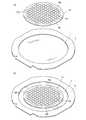
先ず、光デバイスウエーハ10の裏面10bを環状のフレームに装着されたダイシングテープの表面に貼着するウエーハ支持工程を実施する。即ち、図5の(a)および(b)に示すように、環状のフレームFの内側開口部を覆うように外周部が装着されたダイシングテープTの表面に上記光デバイスウエーハ10の裏面10bを貼着する。 First, a wafer support process is performed in which the
上述したウエーハ支持工程を実施したならば、図1に示すレーザー加工装置のチャックテーブル36上に光デバイスウエーハ10のダイシングテープT側を載置する。そして、図示しない吸引手段を作動することにより、ダイシングテープTを介して光デバイスウエーハ10をチャックテーブル36上に吸引保持する(ウエーハ保持工程)。従って、チャックテーブル36に保持された光デバイスウエーハ10は、表面10aが上側となる。 When the wafer support step described above is performed, the dicing tape T side of the
上述したように光デバイスウエーハ10を吸引保持したチャックテーブル36は、加工送り手段37によって撮像手段6の直下に位置付けられる。チャックテーブル36が撮像手段6の直下に位置付けられると、撮像手段6および図示しない制御手段によって光デバイスウエーハ10のレーザー加工すべき加工領域を検出するアライメント作業を実行する。即ち、撮像手段6および図示しない制御手段は、光デバイスウエーハ10の所定方向に形成されているストリート101と、ストリート101に沿ってレーザー光線を照射するレーザー光線照射手段52の集光レンズ528との位置合わせを行うためのパターンマッチング等の画像処理を実行し、レーザー光線照射位置のアライメントを遂行する。また、光デバイスウエーハ10に形成されている上記所定方向に対して直交する方向に延びるストリート101に対しても、同様にレーザー光線照射位置のアライメントが遂行される。 As described above, the chuck table 36 that sucks and holds the
以上のようにしてチャックテーブル36上に保持された光デバイスウエーハ10に形成されているストリート101を検出し、レーザー光線照射位置のアライメントが行われたならば、図6の(a)で示すようにチャックテーブル36をレーザー光線照射手段52の集光レンズ528が位置するレーザー光線照射領域に移動し、所定のストリート101の一端(図6の(a)において左端)を集光レンズ528の直下に位置付ける。そして、集光レンズ528を通して照射されるパルスレーザー光線の集光点Pを光デバイスウエーハ10の表面10a(上面)付近に位置付ける。 If the
次に、レーザー光線照射手段52を作動し集光レンズ528を通して上記図2に示す第1のパルスレーザー光線LB1を照射して加工領域を荒らす第1のレーザー加工工程と、第1のパルスレーザー光線LB1の照射によって荒らされた加工領域に第2のパルスレーザー光線LB2を照射して凹みを形成する第2のレーザー加工工程とを交互に実施するとともに、チャックテーブル36を図6の(a)において矢印X1で示す方向に所定の加工送り速度で移動せしめる。そして、図6の(b)で示すようにレーザー光線照射手段52の集光レンズ528の照射位置がストリート101の他端(図6の(b)において右端)の位置に達したら、パルスレーザー光線の照射を停止するとともにチャックテーブル36の移動を停止する(レーザー加工溝形成工程)。 Next, the laser beam irradiation means 52 is operated to irradiate the first pulse laser beam LB1 shown in FIG. 2 through the
上記レーザー加工溝形成工程における加工条件は、例えば次のように設定されている。
レーザー光線の波長 :532nm、355nm、266nm
繰り返し周波数 :50kHz
平均出力 :2W
第1のパルスレーザー光線LB1:1.5W
第2のパルスレーザー光線LB2:0.5W
遅延時間 :1/1M秒
集光スポット径 :φ15μm
加工送り速度 :100mm/秒The processing conditions in the laser processing groove forming step are set as follows, for example.
Laser beam wavelength: 532 nm, 355 nm, 266 nm
Repetition frequency: 50 kHz
Average output: 2W
First pulse laser beam LB1: 1.5W
Second pulse laser beam LB2: 0.5W
Delay time: 1/1 Msec Condensing spot diameter: φ15 μm
Processing feed rate: 100 mm / sec
上記レーザー加工溝形成工程においては、第1のパルスレーザー光線LB1を照射して加工領域を荒らす第1のレーザー加工工程を実施した直後に、荒らされた加工領域に第2のパルスレーザー光線LB2を照射して凹みを形成する第2のレーザー加工工程が実施されるので、透明部材からなる光デバイスウエーハ10であっても第2のパルスレーザー光線LB2が効果的に吸収されて効率よく凹みが加工される。この第1のパルスレーザー光線LB1を照射して加工領域を荒らす第1のレーザー加工工程と荒らされた加工領域に第2のパルスレーザー光線LB2を照射して凹みを形成する第2のレーザー加工工程とを繰り返し実施することにより、図6の(b)および(c)に示すようにストリート101に沿って連続的な凹みであるレーザー加工溝110が形成される。なお、上述した実施形態においては、第1のレーザー加工工程において照射する第1のパルスレーザー光線LB1の出力が第2のレーザー加工工程において照射する第2のパルスレーザー光線LB2の出力より高い値に設定されているので、加工領域を効果的に荒らすことができる。 In the laser processing groove forming step, immediately after performing the first laser processing step of irradiating the first pulse laser beam LB1 to roughen the processing region, the roughened processing region is irradiated with the second pulse laser beam LB2. Since the second laser processing step for forming the recess is performed, the second pulse laser beam LB2 is effectively absorbed even in the
以上のようにして、光デバイスウエーハ10の所定方向に延在する全てのストリート101に沿って上記レーザー加工溝形成工程を実施したならば、チャックテーブル36を90度回動せしめて、上記所定方向に対して直交する方向に形成された各ストリート101に沿って上記レーザー加工溝形成工程を実施する。 When the laser processing groove forming step is performed along all the
上述したレーザー加工溝形成工程が実施された光デバイスウエーハ10は、外力を付与することにより破断起点となるレーザー加工溝110が形成されたストリート101に沿って破断し、個々の光デバイスに分割するウエーハ分割工程に搬送される。 The
1:レーザー加工装置
2:静止基台
3:チャックテーブル機構
36:チャックテーブル
37:加工送り手段
38:第1の割り出し送り手段
4:レーザー光線照射ユニット支持機構
43:第2の割り出し送り手段
5:レーザー光線照射ユニット
52:レーザー光線照射手段
522:パルスレーザー光線発振手段
523:出力調整手段
524:1/2波長板
525:光分岐手段
526:遅延手段
527:誘導手段
528:集光レンズ
6:撮像手段
8:制御手段
10:光デバイスウエーハ
F:環状のフレーム
T:ダイシングテープ1: laser processing device 2: stationary base 3: chuck table mechanism 36: chuck table 37: processing feed means 38: first index feed means 4: laser beam irradiation unit support mechanism 43: second index feed means 5: laser beam Irradiation unit 52: Laser beam irradiation means 522: Pulse laser beam oscillation means 523: Output adjustment means 524: Half wave plate 525: Light branching means 526: Delay means 527: Guiding means 528: Condensing lens 6: Imaging means 8: Control Means 10: Optical device wafer
F: Ring frame
T: Dicing tape
Claims (3)
Translated fromJapanese被加工物の加工領域に第1のパルスレーザー光線を照射して加工領域を荒らす第1のレーザー加工工程と、
該第1のパルスレーザー光線の直後に該第1のパルスレーザー光線の照射によって荒らされた加工領域に第2のパルスレーザー光線を照射して凹みを形成する第2のレーザー加工工程と、を含み、
該第1のパルスレーザー光線の出力は、該第2のパルスレーザー光線の出力より大きい値に設定され、
該第1のレーザー加工工程と該第2のレーザー加工工程とを繰り返し実施することにより、連続的に凹み加工を施す、
ことを特徴とするレーザー加工方法。A laser processing method for performing laser processing by irradiating a workpiece made of a transparent member with a pulsed laser beam,
A first laser processing step of irradiating a processing region of a workpiece with a first pulsed laser beam to roughen the processing region;
A second laser processing step of forming a recess by irradiating a second pulse laser beam to a processing region roughened by the irradiation of the first pulse laser beam immediately after the first pulse laser beam,
The output of the first pulsed laser beam is set to a value greater than the output of the second pulsed laser beam;
By performing manytimes asa laser processing step of the laser processing step and the second first, subjected to continuous recess machining,
The laser processing method characterized by the above-mentioned.
被加工物を保持する被加工物保持手段と、該被加工物保持手段に保持された被加工物にパルスレーザー光線を照射するパルスレーザー光線照射手段と、該被加工物保持手段と該パルスレーザー光線照射手段とを相対的に移動せしめる移動手段と、該パルスレーザー光線照射手段および該移動手段を制御する制御手段と、を具備し、
該パルスレーザー光線照射手段は、パルスレーザー光線発振器と、該パルスレーザー光線発振器から発振されたパルスレーザー光線を第1の経路に導く第1のパルスレーザー光線と第2の経路に導く第2のパルスレーザー光線とに分光する光分岐手段と、該第2の経路に配設され該第2のパルスレーザー光線を遅延させる遅延手段と、該第1のパルスレーザー光線と該第2のパルスレーザー光線を第3の経路に導く誘導手段と、該第3の経路に配設され該第1のパルスレーザー光線と該第2のパルスレーザー光線を集光して該被加工物保持手段に保持された被加工物に照射する集光器と、を具備しており、
該制御手段は、該移動手段を制御して該被加工物保持手段と該パルスレーザー光線照射手段とを相対的に移動しつつ、該第1のパルスレーザー光線の出力を該第2のパルスレーザー光線の出力より大きい値になるように制御して、該第1のパルスレーザー光線と該第2のパルスレーザー光線を繰り返し照射するように制御することにより、該第1のパルスレーザー光線の照射によって荒らされた加工領域に該第2のパルスレーザー光線を照射して凹みを連続的に形成する、
ことを特徴とするレーザー加工装置。A laser processing apparatus for performing laser processing by irradiating a workpiece made of a transparent member with a pulsed laser beam,
Workpiece holding means for holding a workpiece, pulsed laser beam irradiation means for irradiating a workpiece held on the workpiece holding means with a pulsed laser beam, the workpiece holding means, and the pulsed laser beam irradiation means And a control means for controlling the pulse laser beam irradiation means and the moving means,
The pulse laser beam irradiation means splits a pulse laser beam oscillator, a pulse laser beam oscillated from the pulse laser beam oscillator into a first pulse laser beam that guides the first path and a second pulse laser beam that guides the second path. Light branching means; delay means disposed in the second path for delaying the second pulse laser beam; guidance means for guiding the first pulse laser beam and the second pulse laser beam to the third path; A condenser disposed in the third path for condensing the first pulse laser beam and the second pulse laser beam and irradiating the workpiece held by the workpiece holding means; Has
The control means controls the moving means to relatively move the workpiece holding means and the pulse laser beam irradiation means, and outputs the output of the first pulse laser beam to the output of the second pulse laser beam. controlled to so as to a larger value, by controlling sothat the first pulsed laser beam and the second pulse laser beam is irradiatedrepeatedly until infested by irradiation of the first pulse laser beam machining Irradiating the region with the second pulsed laser beam to form a recess continuously;
Laser processing equipment characterized by that.
Priority Applications (3)
| Application Number | Priority Date | Filing Date | Title |
|---|---|---|---|
| JP2011112484AJP5912287B2 (en) | 2011-05-19 | 2011-05-19 | Laser processing method and laser processing apparatus |
| CN201210153655.3ACN102785028B (en) | 2011-05-19 | 2012-05-17 | Laser processing and laser processing device |
| US13/473,824US9193008B2 (en) | 2011-05-19 | 2012-05-17 | Laser processing method and laser processing apparatus |
Applications Claiming Priority (1)
| Application Number | Priority Date | Filing Date | Title |
|---|---|---|---|
| JP2011112484AJP5912287B2 (en) | 2011-05-19 | 2011-05-19 | Laser processing method and laser processing apparatus |
Publications (2)
| Publication Number | Publication Date |
|---|---|
| JP2012240082A JP2012240082A (en) | 2012-12-10 |
| JP5912287B2true JP5912287B2 (en) | 2016-04-27 |
Family
ID=47150722
Family Applications (1)
| Application Number | Title | Priority Date | Filing Date |
|---|---|---|---|
| JP2011112484AActiveJP5912287B2 (en) | 2011-05-19 | 2011-05-19 | Laser processing method and laser processing apparatus |
Country Status (3)
| Country | Link |
|---|---|
| US (1) | US9193008B2 (en) |
| JP (1) | JP5912287B2 (en) |
| CN (1) | CN102785028B (en) |
Families Citing this family (40)
| Publication number | Priority date | Publication date | Assignee | Title |
|---|---|---|---|---|
| JP5813959B2 (en)* | 2011-02-07 | 2015-11-17 | 株式会社ディスコ | Laser beam irradiation mechanism and laser processing apparatus |
| US8842358B2 (en) | 2012-08-01 | 2014-09-23 | Gentex Corporation | Apparatus, method, and process with laser induced channel edge |
| JP2014124646A (en)* | 2012-12-25 | 2014-07-07 | Disco Abrasive Syst Ltd | Laser machining method and fine particle layer former |
| JP6255255B2 (en)* | 2014-01-27 | 2017-12-27 | 株式会社ディスコ | Optical device processing method |
| US9919502B2 (en) | 2014-04-23 | 2018-03-20 | Schaublin Sa | Method and apparatus for preparing a surface for bonding a material thereto |
| JP6482184B2 (en)* | 2014-05-08 | 2019-03-13 | 株式会社ディスコ | Laser processing equipment |
| JP6320261B2 (en)* | 2014-09-26 | 2018-05-09 | 株式会社ディスコ | Wafer processing method |
| JP6399913B2 (en) | 2014-12-04 | 2018-10-03 | 株式会社ディスコ | Wafer generation method |
| JP6391471B2 (en)* | 2015-01-06 | 2018-09-19 | 株式会社ディスコ | Wafer generation method |
| CN104625423B (en)* | 2015-01-21 | 2016-01-20 | 深圳市创鑫激光股份有限公司 | A kind of laser marking control method, laser marking head and laser marking machine |
| CN104708208B (en)* | 2015-01-23 | 2017-01-04 | 大族激光科技产业集团股份有限公司 | Laser output device and sapphire grooving method thereof |
| JP6395632B2 (en) | 2015-02-09 | 2018-09-26 | 株式会社ディスコ | Wafer generation method |
| JP6395633B2 (en) | 2015-02-09 | 2018-09-26 | 株式会社ディスコ | Wafer generation method |
| JP6494382B2 (en) | 2015-04-06 | 2019-04-03 | 株式会社ディスコ | Wafer generation method |
| JP6429715B2 (en) | 2015-04-06 | 2018-11-28 | 株式会社ディスコ | Wafer generation method |
| JP6425606B2 (en) | 2015-04-06 | 2018-11-21 | 株式会社ディスコ | Wafer production method |
| JP2018523291A (en)* | 2015-06-01 | 2018-08-16 | エバナ テクノロジーズ ユーエービー | Method for scribing semiconductor workpiece |
| JP6472333B2 (en) | 2015-06-02 | 2019-02-20 | 株式会社ディスコ | Wafer generation method |
| JP6482423B2 (en) | 2015-07-16 | 2019-03-13 | 株式会社ディスコ | Wafer generation method |
| JP6482425B2 (en) | 2015-07-21 | 2019-03-13 | 株式会社ディスコ | Thinning method of wafer |
| JP6472347B2 (en) | 2015-07-21 | 2019-02-20 | 株式会社ディスコ | Thinning method of wafer |
| JP6683500B2 (en)* | 2016-02-24 | 2020-04-22 | 株式会社ディスコ | Inspection equipment and laser processing equipment |
| JP6690983B2 (en)* | 2016-04-11 | 2020-04-28 | 株式会社ディスコ | Wafer generation method and actual second orientation flat detection method |
| JP6625926B2 (en) | 2016-04-13 | 2019-12-25 | 株式会社ディスコ | Wafer processing method |
| JP6858587B2 (en) | 2017-02-16 | 2021-04-14 | 株式会社ディスコ | Wafer generation method |
| JP6781650B2 (en)* | 2017-03-13 | 2020-11-04 | 株式会社ディスコ | Laser processing equipment |
| JP6802093B2 (en)* | 2017-03-13 | 2020-12-16 | 株式会社ディスコ | Laser processing method and laser processing equipment |
| JP6781649B2 (en)* | 2017-03-13 | 2020-11-04 | 株式会社ディスコ | Laser processing equipment |
| JP6802094B2 (en)* | 2017-03-13 | 2020-12-16 | 株式会社ディスコ | Laser processing equipment |
| JP6904793B2 (en)* | 2017-06-08 | 2021-07-21 | 株式会社ディスコ | Wafer generator |
| DE102018200029A1 (en)* | 2018-01-03 | 2019-07-04 | Trumpf Laser- Und Systemtechnik Gmbh | Method and laser processing machine for surface structuring laser-transparent workpieces |
| JP2020151736A (en)* | 2019-03-19 | 2020-09-24 | 住友重機械工業株式会社 | Laser control device and pulse laser output device |
| DE102019217577A1 (en)* | 2019-11-14 | 2021-05-20 | Trumpf Laser- Und Systemtechnik Gmbh | Process for laser processing of a workpiece, processing optics and laser processing device |
| JP7467821B2 (en)* | 2020-02-06 | 2024-04-16 | 株式会社東京精密 | Laser processing device and processing method |
| JP2022077223A (en)* | 2020-11-11 | 2022-05-23 | 株式会社ディスコ | Laser processing equipment |
| KR102214104B1 (en)* | 2020-12-03 | 2021-02-09 | 주식회사 아성 | Mask frame surface treatment method using laser cleaning |
| CN114571114B (en)* | 2022-04-14 | 2024-02-09 | 武汉逸飞激光股份有限公司 | Laser dynamic balance welding system and welding method |
| CN114905145A (en)* | 2022-05-19 | 2022-08-16 | 西安空天机电智能制造有限公司 | Multi-light-path switching femtosecond laser processing system and processing method |
| CN116117338A (en)* | 2023-04-20 | 2023-05-16 | 苏州一航电子科技股份有限公司 | Automatic frock tool of plastic part radium carving |
| CN119549896B (en)* | 2025-01-21 | 2025-05-02 | 建德市永喜木业有限公司 | Numerical control engraving machine for wooden bedplate |
Family Cites Families (11)
| Publication number | Priority date | Publication date | Assignee | Title |
|---|---|---|---|---|
| JP4659300B2 (en)* | 2000-09-13 | 2011-03-30 | 浜松ホトニクス株式会社 | Laser processing method and semiconductor chip manufacturing method |
| JP4890746B2 (en) | 2004-06-14 | 2012-03-07 | 株式会社ディスコ | Wafer processing method |
| JP4527488B2 (en)* | 2004-10-07 | 2010-08-18 | 株式会社ディスコ | Laser processing equipment |
| JP4942313B2 (en)* | 2005-07-07 | 2012-05-30 | 株式会社ディスコ | Wafer laser processing method |
| JP4977412B2 (en)* | 2006-07-13 | 2012-07-18 | 株式会社ディスコ | Laser processing equipment |
| JP5103054B2 (en) | 2007-04-27 | 2012-12-19 | サイバーレーザー株式会社 | Laser processing method and laser processing apparatus |
| JP4959422B2 (en)* | 2007-05-30 | 2012-06-20 | 株式会社ディスコ | Wafer division method |
| JP5154838B2 (en)* | 2007-05-31 | 2013-02-27 | 株式会社ディスコ | Laser processing equipment |
| JP2010016116A (en)* | 2008-07-02 | 2010-01-21 | Disco Abrasive Syst Ltd | Method of manufacturing semiconductor device |
| KR101107859B1 (en)* | 2008-09-12 | 2012-01-31 | 오므론 가부시키가이샤 | Method and apparatus for forming scribe line for cutting |
| JP2010142862A (en)* | 2008-12-22 | 2010-07-01 | Cyber Laser Kk | Method for producing nano-periodic structure on surface of dielectric material |
- 2011
- 2011-05-19JPJP2011112484Apatent/JP5912287B2/enactiveActive
- 2012
- 2012-05-17CNCN201210153655.3Apatent/CN102785028B/enactiveActive
- 2012-05-17USUS13/473,824patent/US9193008B2/enactiveActive
Also Published As
| Publication number | Publication date |
|---|---|
| CN102785028B (en) | 2016-12-21 |
| US20120292297A1 (en) | 2012-11-22 |
| US9193008B2 (en) | 2015-11-24 |
| CN102785028A (en) | 2012-11-21 |
| JP2012240082A (en) | 2012-12-10 |
Similar Documents
| Publication | Publication Date | Title |
|---|---|---|
| JP5912287B2 (en) | Laser processing method and laser processing apparatus | |
| JP5010978B2 (en) | Laser processing equipment | |
| JP5154838B2 (en) | Laser processing equipment | |
| JP5284651B2 (en) | Wafer processing method | |
| JP5192213B2 (en) | Laser processing equipment | |
| JP2006159254A (en) | Laser processing equipment | |
| JP4851918B2 (en) | Wafer laser processing method and laser processing apparatus | |
| JP5980504B2 (en) | Wafer processing method and laser processing apparatus | |
| JP4555092B2 (en) | Laser processing equipment | |
| JP2010123723A (en) | Laser processing method of wafer | |
| JP4977412B2 (en) | Laser processing equipment | |
| JP2005297012A (en) | Laser processing equipment | |
| JP5833359B2 (en) | Laser beam irradiation device | |
| JP2008060164A (en) | Wafer laser processing method | |
| JP2009283753A (en) | Laser processing method and laser processing device for wafer | |
| JP6482184B2 (en) | Laser processing equipment | |
| JP2011049454A (en) | Laser processing method of wafer | |
| JP2007190587A (en) | Laser processing equipment | |
| JP5947056B2 (en) | Laser processing method and laser processing apparatus | |
| JP2013102039A (en) | Semiconductor wafer processing method | |
| JP4786997B2 (en) | Laser processing equipment | |
| KR20120129759A (en) | Laser machining method and laser machining apparatus | |
| JP2006289388A (en) | Laser processing equipment | |
| JP6441731B2 (en) | Laser processing equipment | |
| KR102084267B1 (en) | Laser machining apparatus |
Legal Events
| Date | Code | Title | Description |
|---|---|---|---|
| A621 | Written request for application examination | Free format text:JAPANESE INTERMEDIATE CODE: A621 Effective date:20140414 | |
| A977 | Report on retrieval | Free format text:JAPANESE INTERMEDIATE CODE: A971007 Effective date:20150120 | |
| A131 | Notification of reasons for refusal | Free format text:JAPANESE INTERMEDIATE CODE: A131 Effective date:20150224 | |
| A521 | Request for written amendment filed | Free format text:JAPANESE INTERMEDIATE CODE: A523 Effective date:20150422 | |
| A131 | Notification of reasons for refusal | Free format text:JAPANESE INTERMEDIATE CODE: A131 Effective date:20151006 | |
| A521 | Request for written amendment filed | Free format text:JAPANESE INTERMEDIATE CODE: A523 Effective date:20151116 | |
| TRDD | Decision of grant or rejection written | ||
| A01 | Written decision to grant a patent or to grant a registration (utility model) | Free format text:JAPANESE INTERMEDIATE CODE: A01 Effective date:20160308 | |
| A61 | First payment of annual fees (during grant procedure) | Free format text:JAPANESE INTERMEDIATE CODE: A61 Effective date:20160401 | |
| R150 | Certificate of patent or registration of utility model | Ref document number:5912287 Country of ref document:JP Free format text:JAPANESE INTERMEDIATE CODE: R150 | |
| R250 | Receipt of annual fees | Free format text:JAPANESE INTERMEDIATE CODE: R250 | |
| R250 | Receipt of annual fees | Free format text:JAPANESE INTERMEDIATE CODE: R250 | |
| R250 | Receipt of annual fees | Free format text:JAPANESE INTERMEDIATE CODE: R250 | |
| R250 | Receipt of annual fees | Free format text:JAPANESE INTERMEDIATE CODE: R250 | |
| R250 | Receipt of annual fees | Free format text:JAPANESE INTERMEDIATE CODE: R250 | |
| R250 | Receipt of annual fees | Free format text:JAPANESE INTERMEDIATE CODE: R250 | |
| R250 | Receipt of annual fees | Free format text:JAPANESE INTERMEDIATE CODE: R250 |