JP5910748B2 - Orbit generation apparatus, orbit generation method, and orbit generation program - Google Patents
Orbit generation apparatus, orbit generation method, and orbit generation programDownload PDFInfo
- Publication number
- JP5910748B2 JP5910748B2JP2014526710AJP2014526710AJP5910748B2JP 5910748 B2JP5910748 B2JP 5910748B2JP 2014526710 AJP2014526710 AJP 2014526710AJP 2014526710 AJP2014526710 AJP 2014526710AJP 5910748 B2JP5910748 B2JP 5910748B2
- Authority
- JP
- Japan
- Prior art keywords
- trajectory
- angular velocity
- target
- angle
- time
- Prior art date
- Legal status (The legal status is an assumption and is not a legal conclusion. Google has not performed a legal analysis and makes no representation as to the accuracy of the status listed.)
- Active
Links
- 238000000034methodMethods0.000titleclaimsdescription29
- 230000008859changeEffects0.000claimsdescription68
- 230000001133accelerationEffects0.000claimsdescription66
- 238000001514detection methodMethods0.000claimsdescription5
- 238000012937correctionMethods0.000description33
- 238000010586diagramMethods0.000description13
- 238000005070samplingMethods0.000description7
- 230000001172regenerating effectEffects0.000description5
- 230000000694effectsEffects0.000description4
- 238000004519manufacturing processMethods0.000description4
- 230000008569processEffects0.000description4
- 230000007704transitionEffects0.000description4
- 238000004364calculation methodMethods0.000description3
- 238000004891communicationMethods0.000description3
- 238000007796conventional methodMethods0.000description3
- 230000014509gene expressionEffects0.000description3
- 230000003287optical effectEffects0.000description3
- 230000004044responseEffects0.000description2
- NAWXUBYGYWOOIX-SFHVURJKSA-N(2s)-2-[[4-[2-(2,4-diaminoquinazolin-6-yl)ethyl]benzoyl]amino]-4-methylidenepentanedioic acidChemical compoundC1=CC2=NC(N)=NC(N)=C2C=C1CCC1=CC=C(C(=O)N[C@@H](CC(=C)C(O)=O)C(O)=O)C=C1NAWXUBYGYWOOIX-SFHVURJKSA-N0.000description1
- 230000008030eliminationEffects0.000description1
- 238000003379elimination reactionMethods0.000description1
- 238000005516engineering processMethods0.000description1
- 230000005284excitationEffects0.000description1
- 230000007246mechanismEffects0.000description1
- 238000012986modificationMethods0.000description1
- 230000004048modificationEffects0.000description1
- 238000012545processingMethods0.000description1
- 230000008929regenerationEffects0.000description1
- 238000011069regeneration methodMethods0.000description1
- 239000000725suspensionSubstances0.000description1
- XLYOFNOQVPJJNP-UHFFFAOYSA-NwaterSubstancesOXLYOFNOQVPJJNP-UHFFFAOYSA-N0.000description1
Images


Classifications
- B—PERFORMING OPERATIONS; TRANSPORTING
- B64—AIRCRAFT; AVIATION; COSMONAUTICS
- B64G—COSMONAUTICS; VEHICLES OR EQUIPMENT THEREFOR
- B64G3/00—Observing or tracking cosmonautic vehicles
- B—PERFORMING OPERATIONS; TRANSPORTING
- B64—AIRCRAFT; AVIATION; COSMONAUTICS
- B64G—COSMONAUTICS; VEHICLES OR EQUIPMENT THEREFOR
- B64G1/00—Cosmonautic vehicles
- B64G1/22—Parts of, or equipment specially adapted for fitting in or to, cosmonautic vehicles
- B64G1/24—Guiding or controlling apparatus, e.g. for attitude control
- B64G1/242—Orbits and trajectories
- B—PERFORMING OPERATIONS; TRANSPORTING
- B64—AIRCRAFT; AVIATION; COSMONAUTICS
- B64G—COSMONAUTICS; VEHICLES OR EQUIPMENT THEREFOR
- B64G1/00—Cosmonautic vehicles
- B64G1/22—Parts of, or equipment specially adapted for fitting in or to, cosmonautic vehicles
- B64G1/24—Guiding or controlling apparatus, e.g. for attitude control
- B64G1/244—Spacecraft control systems
- B64G1/245—Attitude control algorithms for spacecraft attitude control
- B—PERFORMING OPERATIONS; TRANSPORTING
- B64—AIRCRAFT; AVIATION; COSMONAUTICS
- B64G—COSMONAUTICS; VEHICLES OR EQUIPMENT THEREFOR
- B64G1/00—Cosmonautic vehicles
- B64G1/22—Parts of, or equipment specially adapted for fitting in or to, cosmonautic vehicles
- B64G1/24—Guiding or controlling apparatus, e.g. for attitude control
- B64G1/244—Spacecraft control systems
- B64G1/247—Advanced control concepts for autonomous, robotic spacecraft, e.g. by using artificial intelligence, neural networks or autonomous agents
Landscapes
- Engineering & Computer Science (AREA)
- Remote Sensing (AREA)
- Radar, Positioning & Navigation (AREA)
- Aviation & Aerospace Engineering (AREA)
- Chemical & Material Sciences (AREA)
- Combustion & Propulsion (AREA)
- Automation & Control Theory (AREA)
- Physics & Mathematics (AREA)
- Astronomy & Astrophysics (AREA)
- General Physics & Mathematics (AREA)
- Numerical Control (AREA)
- Control Of Position Or Direction (AREA)
Description
Translated fromJapanese本発明は、軌道生成装置、軌道生成方法および軌道生成プログラムに関し、特に、人工衛星や航空機等の移動体相互間や該移動体と地上局との間の光空間通信の際に、移動中の目標を追尾するための制御対象の軌道として生成した目標角度や目標角速度に到達する前に、軌道変更が発生した場合であっても正確にかつ短時間に軌道の再生成を行うことが可能な軌道生成装置、軌道生成方法および軌道生成プログラムに関する。より具体的には、軌道変更発生時の軌道として設定されていた出力角速度から軌道を再生成することによって、軌道の不連続を回避することができる軌道生成装置、軌道生成方法および軌道生成プログラムに関する。 The present invention relates to a trajectory generation device, a trajectory generation method, and a trajectory generation program, and in particular, during optical space communication between mobile bodies such as artificial satellites and aircraft, and between the mobile body and a ground station. The trajectory can be regenerated accurately and in a short time even if a trajectory change occurs before reaching the target angle or target angular velocity generated as the trajectory of the control target for tracking the target. The present invention relates to a trajectory generation device, a trajectory generation method, and a trajectory generation program. More specifically, the present invention relates to a trajectory generation device, a trajectory generation method, and a trajectory generation program that can avoid a discontinuity of the trajectory by regenerating the trajectory from the output angular velocity set as the trajectory when the trajectory change occurred. .
図7は、特許文献1の特開平7−307703号公報「光空間通信装置および光空間通信装置用のミラー駆動機構」に記載された従来技術の軌道生成装置の内部構成を示すブロック構成図である。該特許文献1に記載された軌道生成装置においては、図7に示すように、制御対象11の角度を現在角度として検出する角度検出器12、目標を追尾させるための制御対象11の目標角度および目標角速度を設定する指令生成器15、角度検出器12が出力する現在角度と指令生成器15が設定した目標角度および目標角速度とから目標追尾用の軌道を生成して目標指令として制御器13に出力する軌道生成器16を少なくとも備え、制御器13にて、軌道生成器16が出力した目標指令と制御対象11の現在角度とに基づいて、位相補償を施して制御対象11の制御信号を生成し、該制御信号を、ドライバ14を経由して制御対象11に出力することにより、制御対象11を目標指令として指示した目標角度および目標角速度に指向させる。 FIG. 7 is a block diagram showing the internal configuration of a prior art trajectory generator described in Japanese Patent Application Laid-Open No. 7-307703 “Optical Space Communication Device and Mirror Drive Mechanism for Optical Space Communication Device”. is there. In the trajectory generating device described in
つまり、指令生成器15にて設定した目標角度および目標角速度と角度検出器12の出力である制御対象11の現在角度とに基づいて軌道生成器16にて軌道を生成し、制御器13への目標指令として出力することによって、制御対象11を目標指令の指示内容へと指向させるように制御している。この制御は、制御対象11の現在角度の情報をフィードバック情報として用いたフィードバック制御系である。 That is, the
図8は、図1に示した従来技術の軌道生成装置にて生成された軌道に関する時間応答を説明するための説明図である。図8において、横軸は時間を示し、縦軸は角速度を示している。図8に示すような軌道生成法を「基本プロファイル」と称している。以下に、図8に示す「基本プロファイル」について説明する。 FIG. 8 is an explanatory diagram for explaining a time response related to the trajectory generated by the prior art trajectory generating apparatus shown in FIG. In FIG. 8, the horizontal axis indicates time, and the vertical axis indicates angular velocity. The trajectory generation method as shown in FIG. 8 is referred to as a “basic profile”. The “basic profile” shown in FIG. 8 will be described below.
時刻t=tsにおいて指令生成器15から軌道生成指令が与えられ、基本プロファイルが生成されるものとする。ここで、軌道生成指令として与えられる目標角速度をωdとし、初速'0'からの加速継続時間をtαとすると、目標角加速度αdは、次の式(1)で与えられる。Time t = ts trajectory generation command is given from the

また、加速時間(加速終了時刻)をt1、等速時間(等速終了時刻)をt2、減速時間(減速終了時刻)をt3とし、軌道生成指令として与えられる目標角度をθd、時刻tにおける軌道生成器16の出力角度をθr、時刻tにおける軌道生成器16の出力角速度をωrとし、軌道生成開始時刻ts(軌道生成時)における角度検出器2の出力である現在角度をθmsとすると、加速時間t1、等速時間t2および減速時間t3は、それぞれ、次の式(2−1)、式(2−2)および式(2−3)で与えられる。Further, the acceleration time (acceleration end time) is t1 , the constant speed time (constant speed end time) is t2 , the deceleration time (deceleration end time) is t3, and the target angle given as the trajectory generation command is θd , The output angle of the
さらに、加速期間A11(ts≦t<ts+t1の期間)、等速期間E11(ts+t1≦t<ts+t2の期間)、減速期間D11(ts+t2≦t≦ts+t3の期間)および軌道生成終了後の終了後期間F11(t>ts+t3の期間)それぞれにおける軌道生成器16の出力角速度ωrは、それぞれ、次の式(3−1)、式(3−2)、式(3−3)および式(3−4)で与えられる。Moreover, (the periodt s ≦ t <t s + t 1) acceleration period A11, constant speed periodE11 (t s + t 1 ≦ t < periodt s + t2), deceleration periodD11 (t s + t 2 ≦ t ≦ ts + periodt 3) and the end of the period after a
また、軌道生成器16の出力角度θrは、サンプリング周波数をΔtとすると、次の式(4)で与えられる。The output angle θr of the
ここで、制御器13への目標指令としては、軌道生成器16の出力である出力角度θrおよび出力角速度ωrを用いる。Here, as the target command to the
前記特許文献1に記載のような従来技術において、基本プロファイルに従って制御対象11が現在角度θmsから目標角度θdに到達する前に、目標角度θdに変更が発生した場合には、軌道の修正が必要になるが、この時の問題点について、図9A及び図9Bを用いて説明する。図9A及び図9Bは、図7に示した従来技術の軌道生成装置の課題について説明するための説明図であり、図9Aには、横軸に時間、縦軸に軌道生成器16の出力である目標角度を示し、図9Bには、横軸に時間、縦軸に目標角速度を示している。In the prior art as described in
図9Aにおいて、太い実線l1は、初期角度から目標角度Aに達するまでの途中で軌道の再生成がなく、軌道を生成した場合の角度θrの推移を示し、図9Bにおいて、太い実線l3は、初期角度から目標角度Aに達するまでの途中で軌道の再生成がなく、軌道を生成した場合の角速度ωrの推移を示している。In FIG. 9A, a thick solid line l1 indicates the transition of the angle θr when the trajectory is generated without regenerating the trajectory on the way from the initial angle to the target angle A. In FIG. 9B, the thick solid line l3 indicates The graph shows the transition of the angular velocity ωr when the trajectory is generated without regenerating the trajectory on the way from the initial angle to the target angle A.
一方、図9Aの点線l2は、初期角度Cからの加速継続時間tαの経過毎に、目標角度が目標角度A、目標角度Bと交互に変更になって、軌道を再生成する場合の角度θrの推移を示している。つまり、図9Aにおいて、軌道O1、O3、O5の場合の目標角度が目標角度Aであり、軌道O2、O4の場合の目標角度が目標角度Bである。初期角度Cからの加速継続時間tαの経過毎に、図9Bに点線l4にて示す角速度ωrの推移のように、角速度ωrが式(3−1)によって目標角速度ωdに一旦は到達するが、同時に、軌道再生成が発生して、t=tsとなってしまうため、式(3−1)により、角速度ωr=0になってしまう。したがって、初期角度Cから加速継続時間tαの経過毎に、図9A、図9Bに示すように、角度θr、角速度ωrに不連続点が発生し、図9A、図9Bの太い実線l1、l3に比べ、点線l2、l4に示すように、目標角度Aまたは目標角度Bに到達するまでに時間がかかるとともに、不連続箇所において制御対象11に不用意な振動を励起させるという問題がある。On the other hand, the
(本発明の目的)
本発明は前述のような問題点に鑑みてなされたものであり、制御対象が目標角度に到達する前に、軌道の変更を要する場合が発生しても、角速度、角度の不連続点を発生させることなく、変更後の軌道を生成することができ、確実かつ短時間に目標角度に到達することが可能な軌道生成装置、軌道生成方法および軌道生成プログラムを提供することを、その目的としている。(Object of the present invention)
The present invention has been made in view of the above-described problems, and even when the trajectory needs to be changed before the control target reaches the target angle, the angular velocity and the angle discontinuity point are generated. The object of the present invention is to provide a trajectory generation device, a trajectory generation method, and a trajectory generation program that can generate a trajectory after change without fail, and can reliably reach the target angle in a short time. .
前述の課題を解決するため、本発明による軌道生成装置、軌道生成方法および軌道生成プログラムは、主に、次のような特徴的な構成を採用している。 In order to solve the above-described problems, the trajectory generation apparatus, trajectory generation method, and trajectory generation program according to the present invention mainly adopt the following characteristic configuration.
(1)本発明による軌道生成装置は、制御対象と、該制御対象の現在角度を出力する角度検出手段と、該制御対象の目標角度と目標角速度とを設定する指令生成手段と、前記現在角度と前記目標角度と前記目標角速度とに基づいて前記制御対象の軌道を与える出力角速度と出力角度とを生成して出力する軌道生成手段と、を少なくとも備えた軌道生成装置であって、
前記指令生成手段において、現在まで設定していた前記目標角度から新たな新目標角度への変化が発生した時、または、現在まで設定していた前記目標角速度から新たな新目標角速度への変化が発生した時、該変化の発生時点において前記軌道生成手段により生成されていた前記出力角速度と、該変化の発生時点における前記現在角度もしくは該変化の発生時点において前記軌道生成手段により生成されていた前記出力角度とに基づいて、前記軌道生成手段にて、前記新目標角度までの角度または前記新目標角速度までの角速度による変更軌道を再生成することを特徴とする。(1) A trajectory generation device according to the present invention includes a control object, an angle detection unit that outputs a current angle of the control object, a command generation unit that sets a target angle and a target angular velocity of the control object, and the current angle And a trajectory generation unit that generates and outputs an output angular velocity and an output angle that give the trajectory to be controlled based on the target angle and the target angular velocity,
In the command generation means, when a change from the target angle set up to the present to a new new target angle occurs, or a change from the target angular velocity set up to the present to a new new target angular velocity occurs. When generated, the output angular velocity generated by the trajectory generating means at the time of occurrence of the change and the current angle at the time of occurrence of the change or the trajectory generating means at the time of occurrence of the change Based on the output angle, the trajectory generating means regenerates the changed trajectory based on the angle up to the new target angle or the angular velocity up to the new target angular velocity.
(2)本発明による軌道生成方法は、制御対象の現在角度を出力する角度検出ステップと、該制御対象の目標角度と目標角速度とを設定する指令生成ステップと、前記現在角度と前記目標角度と前記目標角速度とに基づいて前記制御対象の軌道を与える出力角速度と出力角度とを生成して出力する軌道生成ステップと、を少なくとも有してなる軌道生成方法であって、
前記指令生成ステップにおいて、現在まで設定していた前記目標角度から新たな新目標角度への変化が発生した時、または、現在まで設定していた前記目標角速度から新たな新目標角速度への変化が発生した時、該変化の発生時点において前記軌道生成ステップにより生成されていた前記出力角速度と、該変化の発生時点における前記現在角度もしくは該変化の発生時点において前記軌道生成ステップにより生成されていた前記出力角度とに基づいて、前記軌道生成ステップにて、前記新目標角度までの角度または前記新目標角速度までの角速度による変更軌道を再生成することを特徴とする。(2) A trajectory generation method according to the present invention includes an angle detection step of outputting a current angle of a control target, a command generation step of setting a target angle and a target angular velocity of the control target, the current angle and the target angle. A trajectory generation method comprising at least an output angular velocity and an output angle that give the trajectory to be controlled based on the target angular velocity, and a trajectory generation step.
In the command generation step, when a change from the target angle set up to the present to a new new target angle occurs, or a change from the target angular velocity set up to the present to a new new target angular velocity occurs. When generated, the output angular velocity generated by the trajectory generation step at the time of occurrence of the change and the current angle at the time of occurrence of the change or the trajectory generation step at the time of occurrence of the change Based on the output angle, the trajectory generating step regenerates a changed trajectory based on the angle up to the new target angle or the angular velocity up to the new target angular velocity.
(3)本発明による軌道生成プログラムは、少なくとも前記(2)に記載の軌道生成方法を、コンピュータによって実行可能なプログラムとして実施していることを特徴とする。 (3) The trajectory generation program according to the present invention is characterized in that at least the trajectory generation method described in (2) is implemented as a program executable by a computer.
本発明の軌道生成装置、軌道生成方法および軌道生成プログラムによれば、以下のような効果を奏することができる。 According to the trajectory generation device, trajectory generation method, and trajectory generation program of the present invention, the following effects can be obtained.
すなわち、制御対象が目標角度到達前に目標角度、目標角速度が変更になった場合には、軌道生成手段(軌道生成ステップ)が出力する出力角速度を維持した状態のまま変更軌道を再生成することを可能にしているので、軌道に角速度、角度の不連続点を発生させることなく、変更軌道の再生成が可能であり、制御対象に不用意な振動を励起させることを確実に防止することができる。 That is, when the target angle and target angular velocity are changed before the target angle reaches the target angle, the changed trajectory is regenerated while maintaining the output angular velocity output by the trajectory generating means (trajectory generating step). Therefore, it is possible to regenerate the modified trajectory without causing angular velocity and angular discontinuities in the trajectory, and to reliably prevent inadvertent vibrations from being excited in the controlled object. it can.
また、再生成した変更軌道は、指令生成手段(指令生成ステップ)にて設定した目標角度に到達することができるだけでなく、等速時において指令生成手段(指令生成ステップ)にて設定した目標角速度を満たすことも可能になる。言い換えると、目標角速度は一定の角速度のままにして、目標角度を何度変更しても、等速時には、常に、一定角速度の軌道を生成することができ、制御対象を一定角速度に制御するレート制御を実現することと目標角度に到達することとの両立を図ることが可能である。 The regenerated changed trajectory can not only reach the target angle set by the command generation means (command generation step) but also the target angular velocity set by the command generation means (command generation step) at the constant speed. It is also possible to satisfy. In other words, no matter how many times the target angle is changed with the target angular velocity kept constant, a constant angular velocity trajectory can always be generated at constant speed, and the rate at which the controlled object is controlled to a constant angular velocity. It is possible to achieve both control and reaching the target angle.
以下、本発明による軌道生成装置、軌道生成方法および軌道生成プログラムの好適な実施形態について添付図を参照して説明する。なお、以下の説明においては、本発明による軌道生成装置および軌道生成方法について説明するが、かかる軌道生成方法をコンピュータにより実行可能な軌道生成プログラムとして実施するようにしても良いし、あるいは、軌道生成プログラムをコンピュータにより読み取り可能な記録媒体に記録するようにしても良いことは言うまでもない。 Preferred embodiments of a trajectory generation device, trajectory generation method, and trajectory generation program according to the present invention will be described below with reference to the accompanying drawings. In the following description, the trajectory generation apparatus and trajectory generation method according to the present invention will be described. However, the trajectory generation method may be implemented as a trajectory generation program executable by a computer, or the trajectory generation. Needless to say, the program may be recorded on a computer-readable recording medium.
(本発明の特徴)
本発明の実施形態の説明に先立って、本発明の特徴についてその概要をまず説明する。本発明は、制御対象と、該制御対象の現在角度を出力する角度検出手段と、該制御対象の目標角度と目標角速度とを設定する指令生成手段と、前記現在角度と前記目標角度と前記目標角速度とから軌道を生成する軌道生成手段とを少なくとも備えた軌道生成装置において、前記指令生成手段にて、設定していた現在の目標角度から新目標角度への変化または現在の目標角速度から新目標角速度への変化が発生した時、該変化の発生時点において前記軌道生成手段により生成されていた出力角速度と、該変化の発生時点における前記現在角度もしくは該変化の発生時点において前記軌道生成手段により生成されていた出力角度と、に基づいて、前記新目標角度までの角度または角速度による変更軌道を前記軌道生成手段にて再生成することを主要な特徴としている。(Features of the present invention)
Prior to the description of the embodiments of the present invention, an outline of the features of the present invention will be described first. The present invention includes a control object, angle detection means for outputting a current angle of the control object, command generation means for setting a target angle and a target angular velocity of the control object, the current angle, the target angle, and the target A trajectory generating apparatus comprising at least a trajectory generating means for generating a trajectory from an angular velocity, wherein the command generating means changes from the current target angle set to the new target angle or a new target from the current target angular velocity. When a change to the angular velocity occurs, the output angular velocity generated by the trajectory generating means at the time of the change and the current angle at the time of the change or generated by the trajectory generating means at the time of the change. Based on the output angle that has been set, the trajectory generating means regenerates the changed trajectory based on the angle or angular velocity up to the new target angle. It is characterized such.
而して、制御対象が目標角度到達前であっても、軌道に角速度、角度の不連続点を発生させることなく、変化の発生時点において前記軌道生成手段により生成されていた出力角速度を維持したまま、軌道を変更することが可能になり、制御対象に不用意な振動を励起させることを確実に防止することができるとともに、制御対象をより短時間に目標角度にまで到達させることができる。 Thus, even if the object to be controlled is before reaching the target angle, the output angular velocity generated by the trajectory generating means at the time of occurrence of the change is maintained without generating the angular velocity and the discontinuity of the angle in the trajectory. As a result, the trajectory can be changed, and it is possible to reliably prevent inadvertent vibrations from being excited in the controlled object and to reach the target angle in a shorter time.
(本発明の実施形態の構成例)
次に、本発明による軌道生成装置の実施形態として、その構成例を説明する。図1は、本発明の実施形態に係る軌道生成装置の内部構成の一例を示すブロック構成図である。図1に示す軌道生成装置は、図7に示した従来技術の軌道生成装置の場合と同様、目標追尾用の制御対象1、制御対象1の現在角度を出力する角度検出器2、軌道生成器6が目標指令として生成した軌道と角度検出器2が検出した現在角度とから制御対象1を制御する制御信号を生成する制御器3、制御器3が生成した制御信号を制御対象1に対して出力するドライバ4、制御対象1を目標に追尾させるための目標角度と目標角速度とを設定する指令生成器5、および、角度検出器2が検出した現在角度と指令生成器5が設定した目標角度および目標角速度とに基づいて目標追尾用の制御対象1の軌道を与える出力角速度と出力角度とを目標指令として生成して出力する軌道生成器6を少なくとも含んで構成されている。(Configuration example of embodiment of the present invention)
Next, a configuration example will be described as an embodiment of the trajectory generation device according to the present invention. FIG. 1 is a block configuration diagram illustrating an example of an internal configuration of a trajectory generation device according to an embodiment of the present invention. The trajectory generator shown in FIG. 1 is similar to the prior art trajectory generator shown in FIG. 7, the
ここで、図1に示す軌道生成装置においては、図7に示した従来技術の軌道生成装置の場合と同様、角度検出器2が出力する現在角度と指令生成器5にて指示した目標角度および目標角速度とに基づいて、制御器3にて位相補償を施して制御対象1の制御信号を生成し、該制御信号を、ドライバ4を経由して制御対象1に出力することにより、制御対象1を指令生成器5にて指示した目標角度および目標角速度に指向させる。 Here, in the trajectory generating device shown in FIG. 1, as in the case of the prior art trajectory generating device shown in FIG. 7, the current angle output from the
つまり、指令生成器5にて設定した目標角度および目標角速度と角度検出器2の出力である制御対象11の現在角度とに基づいて軌道生成器6にて軌道を生成し、制御器13への目標指令として出力することによって、制御対象11を目標指令の指示内容へと指向させるように制御している。この制御は、図7に示した従来技術の軌道生成装置の場合と同様、制御対象1の現在角度の情報をフィードバック情報として用いたフィードバック制御系である。ただし、図1に示す軌道生成装置においては、特に、軌道生成器6が有する機能が、図7に示した従来技術の軌道生成装置の軌道生成器16の場合とは大きく異なっている。 That is, the
次に、図1に示す軌道生成装置の軌道生成器6の機能の詳細について説明する。まず、時刻t=tsにおいて、指令生成器5にて軌道生成指令が与えられた場合(つまり、軌道修正開始時刻tsにおいて目標角度か目標角速度かのいずれかが変更になったことが指令生成器5から軌道生成器6に通知されてきた場合)について、目標角度をθd、目標角速度をωd、目標角速度の正数表示をωdd(>0)、目標角加速度をαdとし、かつ、
(1)目標角度θd≧軌道生成器6の出力角度θrsの場合は、目標角速度ωdおよび目標角加速度αdが次の式(5−1)で与えられ、
(2)目標角度θd<軌道生成器6の出力角度θrsの場合は、目標角速度ωdおよび目標角加速度αdが次の式(5−2)で与えられるものとする。Next, details of the function of the
(1) When the target angle θd ≧ the output angle θrs of the
(2) When the target angle θd <the output angle θrs of the
本実施形態における軌道生成器6における軌道生成のパターンとしては、加速からの軌道生成パターン、等速からの軌道生成パターン、減速からの軌道生成パターン、停止からの軌道生成パターンの4パターンがあり、以下に順次説明する。なお、軌道生成器6内に備えている比較手段によって、目標角度θdまたは目標角速度ωdの変化の発生時点における軌道生成器6の出力角速度ωrと目標角速度ωdとを比較した結果に基づいて、4つの軌道生成パターンのいずれを用いて変更軌道を再生成するかが選択される。There are four patterns of trajectory generation in the
ここで、加速時間(加速終了時刻)をt1、等速時間(等速終了時刻)をt2、減速時間(減速終了時刻)をt3とする。また、目標角度をθd、目標角速度をωd、時刻tにおける軌道生成器6の出力である出力角度をθr、時刻tにおける軌道生成器6の出力である出力角速度をωrとする。また、軌道修正開始時刻ts(軌道修正時)における軌道生成器6の出力である出力角度をθrsとし、軌道修正時刻ts(軌道修正時)における軌道生成器6の出力である出力角速度をωrsとする。Here, the acceleration time (acceleration end time) is t1 , the constant speed time (constant speed end time) is t2 , and the deceleration time (deceleration end time) is t3 . The target angle is θd , the target angular velocity is ωd , the output angle that is the output of the
また、角度検出器2の出力である現在角度をθmとする。また、時刻t>(軌道修正開始時刻ts+減速時間t3)の関係が成立している時間帯(すなわち、制御対象1が目標角度θdに到達した後の時間帯)において、指令生成器5から軌道生成指令が与えられた場合は、その時点(軌道修正開始時刻ts)における軌道生成器6の出力角度θrsは、現在角度θmに変更され、
(軌道生成器6の出力角度θrs=現在角度θm)
になるものとする。In addition, the current angle that is the output of the
(Output angle θrs of the
Shall be.
(1)加速からの軌道生成パターン
図2に示すように、加速から軌道を生成する場合は、加速時間(加速終了時刻)t1、等速時間(等速終了時刻)t2および減速時間(減速終了時刻)t3は、それぞれ、次の式(6−1)、式(6−2)および式(6−3)で与えられる。ここで、図2は、図1に示す軌道生成装置の軌道生成器6において加速からの軌道生成パターンの一例を説明するための説明図である。(1) Trajectory generation pattern from acceleration As shown in FIG. 2, when generating a trajectory from acceleration, acceleration time (acceleration end time) t1 , constant speed time (constant speed end time) t2 and deceleration time ( deceleration ending time)t 3, respectively, the following equation (6-1) is given by equation (6-2) and (6-3). Here, FIG. 2 is an explanatory diagram for explaining an example of a trajectory generation pattern from acceleration in the
また、加速期間A1(ts≦t<ts+t1の期間)、等速期間E1(ts+t1≦t<ts+t2の期間)、減速期間D1(ts+t2≦t≦ts+t3の期間)および軌道生成終了後の終了後期間F1(t>ts+t3の期間)の各期間における軌道生成器6の出力角速度ωrは、それぞれ、次の式(7−1)、式(7−2)、式(7−3)および式(7−4)で与えられる。Moreover, (the period oft s ≦ t <t s + t 1) acceleration period A1, constant speed periodE1 (t s + t 1 ≦ t < periodt s + t2), deceleration periodD1 (t s + t 2 ≦ t ≦ ts + periodt 3) and the output angular velocity omegar of the
したがって、軌道修正時刻tsから減速時間(減速終了時刻)t3に到達するまでの間の出力角速度ωrの変化によって囲まれる面積は、図2に示すように、
(目標角度θd−軌道修正時刻tsにおける軌道生成器6の出力角度θrs)
として与えられる。Therefore, the area surrounded by the change in the output angular velocity omegar of between trajectory correction time ts until reaching the deceleration time (deceleration ending time) t3, as shown in FIG. 2,
(Target angle thetad - Output angle thetars trajectory generator 6 in course correction timet s)
As given.
また、軌道生成器6の出力である出力角度θrは、サンプリング周波数をΔtとすると、次の式(8)で与えられる。Further, the output angle θr that is the output of the
(2)等速からの軌道生成パターン
図3に示すように、等速から軌道を生成する場合は、加速時間(加速終了時刻)t1、等速時間(等速終了時刻)t2および減速時間(減速終了時刻)t3は、それぞれ、次の式(9−1)、式(9−2)および式(9−3)で与えられる。ここで、図3は、図1に示す軌道生成装置の軌道生成器6において等速からの軌道生成パターンの一例を説明するための説明図である。(2) Trajectory generation pattern from constant speed As shown in FIG. 3, when generating a trajectory from constant speed, acceleration time (acceleration end time) t1 , constant speed time (constant speed end time) t2 and deceleration time (deceleration ending time)t 3, respectively, the following equation (9-1) is given by equation (9-2) and (9-3). Here, FIG. 3 is an explanatory diagram for explaining an example of a trajectory generation pattern from a constant speed in the
また、等速期間E2(ts≦t<ts+t2の期間)、減速期間D2(ts+t2≦t≦ts+t3の期間)および軌道生成終了後の終了後期間F2(t>ts+t3の期間)の各期間における軌道生成器6の出力角速度ωrは、それぞれ、次の式(10−1)、式(10−2)および式(10−3)で与えられる。Moreover, constant speed period E2(t s ≦t<periodt s + t2), deceleration periodD2 (t s + t 2 ≦ t ≦ t s + periodt 3) and end after a period of post-trajectory generation completion F2 (t The output angular velocity ωr of the
したがって、軌道修正時刻tsから減速時間(減速終了時刻)t3に到達するまでの間の出力角速度ωrの変化によって囲まれる面積は、図3に示すように、図2の場合と同様、
(目標角度θd−軌道修正時刻tsにおける軌道生成器6の出力角度θrs)
として与えられる。Therefore, the area surrounded by the change in the output angular velocity omegar of between trajectory correction time ts until reaching the deceleration time (deceleration ending time) t3, as shown in FIG. 3, as in the case of FIG. 2,
(Target angle thetad - Output angle thetars trajectory generator 6 in course correction timet s)
As given.
また、軌道生成器6の出力である出力角度θrは、サンプリング周波数をΔtとすると、式(8)と同様の次の式(11)で与えられる。The output angle θr that is the output of the
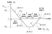
(3)減速からの軌道生成パターン
図4に示すように、減速から軌道を生成する場合は、加速時間(この場合は初期減速時間すなわち初期減速終了時刻)t1、等速時間(等速終了時刻)t2および減速時間(減速終了時刻)t3は、それぞれ、次の式(12−1)、式(12−2)および式(12−3)で与えられる。ここで、図4は、図1に示す軌道生成装置の軌道生成器6において減速からの軌道生成パターンの一例を説明するための説明図である。(3) Trajectory generation pattern from deceleration As shown in FIG. 4, when generating a trajectory from deceleration, acceleration time (in this case, initial deceleration time, that is, initial deceleration end time) t1 , constant velocity time (constant velocity end) time)t 2 and deceleration time (deceleration ending time)t 3, respectively, the following equation (12-1), is given by the equation (12-2) and (12-3). Here, FIG. 4 is an explanatory diagram for explaining an example of a trajectory generation pattern from deceleration in the
また、初期減速期間A3(ts≦t<ts+t1の期間)、等速期間E3(ts+t1≦t<ts+t2の期間)、減速期間D3(ts+t2≦t≦ts+t3の期間)および軌道生成終了後の終了後期間F3(t>ts+t3の期間)の各期間における軌道生成器6の出力角速度ωrは、それぞれ、次の式(13−1)、式(13−2)、式(13−3)および式(13−4)で与えられる。The initial deceleration period A3(t s ≦t<periodt s + t1), a constant speed periodE3 (t s + t 1 ≦ t < periodt s + t2), deceleration periodD3 (t s + t 2 ≦ t ≦ ts + t3 ) and the post-end period F3 (t> ts + t3 period) after the end of trajectory generation, the output angular velocity ωr of the
したがって、軌道修正時刻tsから減速時間(減速終了時刻)t3に到達するまでの間の出力角速度ωrの変化によって囲まれる面積は、図4に示すように、図2の場合と同様、
(目標角度θd−軌道修正時刻tsにおける軌道生成器6の出力角度θrs)
として与えられる。Therefore, the area surrounded by the change in the output angular velocity omegar of between trajectory correction time ts until reaching the deceleration time (deceleration ending time) t3, as shown in FIG. 4, as in the case of FIG. 2,
(Target angle thetad - Output angle thetars trajectory generator 6 in course correction timet s)
As given.
また、軌道生成器6の出力である出力角度θrは、サンプリング周波数をΔtとすると、式(8)と同様の次の式(14)で与えられる。Further, the output angle θr that is the output of the
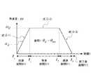
(4)停止からの軌道生成パターン
図5に示すように、停止時間(停止終了時刻)をt0とすると、停止から軌道を生成する場合は、停止時間(停止終了時刻)t0、加速時間(加速終了時刻)t1、等速時間(等速終了時刻)t2および減速時間(減速終了時刻)t3は、それぞれ、次の式(15−1)、式(15−2)、式(15−3)および式(15−4)で与えられる。ここで、図5は、図1に示す軌道生成装置の軌道生成器6において停止からの軌道生成パターンの一例を説明するための説明図である。(4) Trajectory generation pattern from stop As shown in FIG. 5, when the stop time (stop end time) is t0 , when generating a trajectory from the stop, stop time (stop end time) t0 , acceleration time (Acceleration end time) t1 , constant speed time (constant speed end time) t2, and deceleration time (deceleration end time) t3 are respectively expressed by the following equations (15-1), (15-2), and (3): It is given by (15-3) and formula (15-4). Here, FIG. 5 is an explanatory diagram for explaining an example of the trajectory generation pattern from the stop in the
また、停止期間S4(ts≦t<ts+t0の期間)、加速期間A4(ts+t0≦t<ts+t1の期間)、等速期間E4(ts+t1≦t<ts+t2の期間)、減速期間D4(ts+t2≦t≦ts+t3の期間)および軌道生成終了後の終了後期間F4(t>ts+t3の期間)の各期間における軌道生成器6の出力角速度ωrは、それぞれ、次の式(16−1)、式(16−2)、式(16−3)、式(16−4)および式(16−5)で与えられる。Moreover, (the period oft s ≦ t <t s + t 0) suspension period S4, the acceleration periodA4 (t s + t 0 ≦ t < periodt s + t1), a constant speed periodE4 (t s + t 1 ≦ t < periodts + t2), in each period of the deceleration periodD4 (t s + t 2 ≦ t ≦ t s + periodt 3) and the trajectory generation after the end after the end time F4(t> periodt s + t3) The output angular velocity ωr of the
したがって、軌道修正時刻tsから減速時間(減速終了時刻)t3に到達するまでの間の出力角速度ωrの変化によって囲まれる面積は、図5に示すように、図2の場合と同様、
(目標角度θd−軌道修正時刻tsにおける軌道生成器6の出力角度θrs)
として与えられる。Therefore, the area surrounded by the change in the output angular velocity omegar of between trajectory correction time ts until reaching the deceleration time (deceleration ending time) t3, as shown in FIG. 5, as in the case of FIG. 2,
(Target angle thetad - Output angle thetars trajectory generator 6 in course correction timet s)
As given.
また、軌道生成器6の出力である出力角度θrは、サンプリング周波数をΔtとすると、式(8)と同様の次の式(17)で与えられる。Further, the output angle θr that is the output of the
(実施形態の動作の説明)
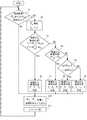
次に、図1ないし図5に本発明の一実施形態として示した軌道生成装置の動作について図6のフローチャートを用いて説明する。図6は、図1ないし図5に示した軌道生成装置の動作の一例を説明するためのフローチャートであり、前述した4つの軌道生成パターン(すなわち、加速からの軌道生成パターン、等速からの軌道生成パターン、減速からの軌道生成パターン、停止からの軌道生成パターンの4パターン)を切り替える動作の一例を説明している。(Description of operation of embodiment)
Next, the operation of the trajectory generating apparatus shown as one embodiment of the present invention in FIGS. 1 to 5 will be described using the flowchart of FIG. FIG. 6 is a flowchart for explaining an example of the operation of the trajectory generation apparatus shown in FIG. 1 to FIG. 5. The four trajectory generation patterns described above (that is, trajectory generation patterns from acceleration, trajectories from constant speed). An example of the operation of switching the generation pattern, the trajectory generation pattern from deceleration, and the four trajectory generation patterns from stop) is described.
図6のフローチャートにおいて、まず、軌道変更の要否すなわち目標角度θdまたは目標角速度ωdd(>0)の変更の有無を判定する(ステップS1)。指令生成器5において、目標角度θdまたは目標角速度ωddが変更されて、つまり、現在まで設定していた目標角度θdから新たな新目標角度への変化が発生して、または、現在まで設定していた目標角速度ωdd(>0)から新たな新目標角速度への変化が発生して、軌道の変更が必要な場合には(ステップS1のYES)、該変化の発生時点として、軌道修正開始時刻ts(軌道修正時)を、
ts=t
と設定することにより、現在時刻tに更新する(ステップS2)。In the flowchart of FIG. 6, first, it is determined whether or not the trajectory needs to be changed, that is, whether or not the target angle θd or the target angular velocity ωdd (> 0) has been changed (step S1). In the
ts = t
Is updated to the current time t (step S2).
次いで、加速から変更軌道を再生成するパターンか否かをまず判定する(ステップS3)。前記変化の発生時点の軌道修正開始時刻ts(軌道修正時)における目標角速度ωdが軌道生成器6の出力角速度ωrsよりも大きい(0<ωrs<ωd、または、0>ωrs>ωd)場合は(ステップS3のYES)、加速から変更軌道を再生成するパターンであるものと判定して、図2の説明図において説明したように、軌道生成時にさらなる加速が必要であるので、加速からの軌道生成パターンを選択して、前述した式(6−1)、式(6−2)および式(6−3)を用いて、加速時間t1、等速時間t2および減速時間t3それぞれを計算する(ステップS6)。Next, it is first determined whether or not the pattern is to regenerate the changed trajectory from the acceleration (step S3). The target angular velocity ωd at the trajectory correction start time ts (at the time of trajectory correction) when the change occurs is larger than the output angular velocity ωrs of the trajectory generator 6 (0 <ωrs <ωd or 0> ωrs. > Ωd ) (YES in step S3), it is determined that the changed trajectory is regenerated from acceleration, and further acceleration is required during trajectory generation as described in the explanatory diagram of FIG. Therefore, the trajectory generation pattern from the acceleration is selected, and the acceleration time t1 , constant velocity time t2, and equation (6-1), equation (6-2), and equation (6-3) are used. respectively calculate the deceleration timet 3 (step S6).
一方、前記変化の発生時点の軌道修正開始時刻ts(軌道修正時)における目標角速度ωdが軌道生成器6の出力角速度ωrsよりも大きくない場合は(ステップS3のNO)、加速からの変更軌道の再生成が不要な場合であるものと判定して、次に、等速から変更軌道を再生成するパターンか否かを判定する(ステップS4)。前記変化の発生時点の軌道修正開始時刻ts(軌道修正時)における目標角速度ωdが軌道生成器6の出力角速度ωrsと等しい(ωrs=ωd)場合は(ステップS4のYES)、等速から変更軌道を再生成するパターンであるものと判定して、図3の説明図において説明したように、等速からの軌道生成パターンを選択して、前述した式(9−1)、式(9−2)および式(9−3)を用いて、加速時間t1、等速時間t2および減速時間t3それぞれを計算する(ステップS7)。On the other hand, if the target angular velocity ωd at the trajectory correction start time ts (at the time of trajectory correction) at the time of occurrence of the change is not greater than the output angular velocity ωrs of the trajectory generator 6 (NO in step S3), It is determined that it is not necessary to regenerate the modified trajectory, and it is then determined whether the pattern is a pattern for regenerating the modified trajectory from a constant speed (step S4). When the target angular velocity ωd at the trajectory correction start time ts (at the time of trajectory correction) at the time of occurrence of the change is equal to the output angular velocity ωrs of the trajectory generator 6 (ωrs = ωd ) (YES in step S4), It is determined that the change trajectory is regenerated from the constant speed, and the trajectory generation pattern from the constant speed is selected as described in the explanatory diagram of FIG. Acceleration time t1 , constant velocity time t2 and deceleration time t3 are calculated using equation (9-2) and equation (9-3) (step S 7).
また、前記変化の発生時点の軌道修正開始時刻ts(軌道修正時)における目標角速度ωdが軌道生成器6の出力角速度ωrsと等しくない場合は(ステップS4のNO)、等速からの変更軌道の再生成が不要な場合であるものと判定して、次に、減速から変更軌道を再生成するパターンか否かを判定する(ステップS5)。前記変化の発生時点の軌道修正開始時刻ts(軌道修正時)における目標角速度ωdと軌道生成器6の出力角速度ωrsとの符号(sgn)を比較して、両者(sgn)の符号が一致した場合は(ステップS5のYES)、減速から変更軌道を再生成するパターンであるものと判定して、図4の説明図において説明したように、減速からの軌道生成パターンを選択して、前述した式(12−1)、式(12−2)および式(12−3)を用いて、加速時間(初期減速時間)t1、等速時間t2および減速時間t3それぞれを計算する(ステップS8)。In addition, when the target angular velocity ωd at the trajectory correction start time ts (at the time of trajectory correction) at the time of occurrence of the change is not equal to the output angular velocity ωrs of the trajectory generator 6 (NO in step S4), It is determined that it is not necessary to regenerate the modified trajectory, and it is then determined whether the pattern is a pattern for regenerating the modified trajectory from deceleration (step S5). The sign (sgn) of the target angular velocity ωd and the output angular velocity ωrs of the
また、前記変化の発生時点の軌道修正開始時刻ts(軌道修正時)における目標角速度ωdと軌道生成器6の出力角速度ωrsとの符号(sgn)が一致しない場合は(ステップS5のNO)、停止からの変更軌道の再生成を行う場合であるものと判定して、前述した式(15−1)、式(15−2)、式(15−3)および式(15−4)を用いて、停止時間t0、加速時間t1、等速時間t2および減速時間t3それぞれを計算する(ステップS9)。Also, if the sign of the output angular velocity omegars of target angular velocity omegad and
次に、ステップS1において、目標角度θdまたは目標角速度ωddの変更がなく、変更軌道の再生成が不要な場合(ステップS1のNO)、または、変更軌道の再生成が必要な場合としてステップS6、ステップS7、ステップS8、ステップS9それぞれにおける時間の計算処理が終了した場合には、ステップS10に移行する。ステップS10においては、変更軌道の再生成が不要な場合は、軌道生成器6は、今までと同じ出力角速度ωr、出力角度θrを目標指令として出力する(ステップS10)。Next, in step S1, if there is no change in the target angle θd or the target angular velocity ωdd and it is not necessary to regenerate the changed trajectory (NO in step S1), or if it is necessary to regenerate the changed trajectory When the time calculation process in each of S6, S7, S8, and S9 is completed, the process proceeds to step S10. In step S10, when it is not necessary to regenerate the changed trajectory, the
一方、変更軌道の再生成が必要な場合おいては、軌道生成器6は、新たな新目標角度までの角度または新たな新目標角速度までの角速度による変更軌道を再生成するために、前記変化の発生時点において軌道生成器6により生成されていた出力角速度ωrsと、前記変化の発生時点における制御対象1の現在角度もしくは前記変化の発生時点において軌道生成器6により生成されていた出力角度θrsとに基づいて、前記変化の発生時点の軌道修正開始時刻ts(軌道修正時)以降の任意の時刻tにおける軌道生成器6の出力角速度ωrおよび該時刻tにおける軌道生成器6の出力角度θrを、それぞれの場合に応じた式(7−1)、式(7−2)、式(7−3)、式(7−4)および式(8)、または、式(10−1)、式(10−2)、式(10−3)および式(11)、または、式(13−1)、式(13−2)、式(13−3)、式(13−4)および式(14)、または、式(16−1)、式(16−2)、式(16−3)、式(16−4)、式(16−5)および式(14)のいずれかに基づいて、計算して、制御器3への目標指令として出力する(ステップS10)。On the other hand, when it is necessary to regenerate the changed trajectory, the
つまり、ステップS10においては、4つの軌道生成パターン毎に以下のように処理する。ステップS6において加速からの軌道生成パターンを実行しようとする場合は、次にステップS1において軌道変更が必要になるまで、式(7−1)、式(7−2)、式(7−3)、式(7−4)に基づいて、加速期間A1、等速期間E1、減速期間D1、終了後期間F1の各期間毎の時刻tにおける軌道生成器6の出力角速度ωrを計算し、式(8)に基づいて、時刻tにおける軌道生成器6の出力角度θrを計算する。That is, in step S10, processing is performed as follows for each of the four trajectory generation patterns. If the trajectory generation pattern from acceleration is to be executed in step S6, the formula (7-1), formula (7-2), and formula (7-3) until the trajectory change is required in step S1. Based on the equation (7-4), the output angular velocity ωr of the
また、ステップS7において等速からの軌道生成パターンを実行しようとする場合は、次にステップS1において軌道変更が必要になるまで、式(10−1)、式(10−2)、式(10−3)に基づいて、等速期間E2、減速期間D2、終了後期間F2の各期間毎の時刻tにおける軌道生成器6の出力角速度ωrを計算し、式(11)に基づいて、時刻tにおける軌道生成器6の出力角度θrを計算する。If it is desired to execute the trajectory generation pattern from the constant speed in step S7, the equations (10-1), (10-2), and (10) until the trajectory change is required in step S1. -3), the output angular velocity ωr of the
また、ステップS8において減速からの軌道生成パターンを実行しようとする場合は、次にステップS1において軌道変更が必要になるまで、式(13−1)、式(13−2)、式(13−3)、式(13−4)に基づいて、初期減速期間A3、等速期間E3、減速期間D3、終了後期間F3の各期間毎の時刻tにおける軌道生成器6の出力角速度ωrを計算し、式(14)に基づいて、時刻tにおける軌道生成器6の出力角度θrを計算する。Further, when the trajectory generation pattern from deceleration is to be executed in step S8, the equations (13-1), (13-2), and (13-) until the trajectory change is required in step S1. 3) Based on the equation (13-4), the output angular velocity ωr of the
また、ステップS9において停止からの軌道生成パターンを実行しようとする場合は、次にステップS1において軌道変更が必要になるまで、式(16−1)、式(16−2)、式(16−3)、式(16−4)、式(16−5)に基づいて、停止期間S4、加速期間A4、等速期間E4、減速期間D4、終了後期間F4の各期間毎の時刻tにおける軌道生成器6の出力角速度ωrを計算し、式(17)に基づいて、時刻tにおける軌道生成器6の出力角度θrを計算する。Further, when the trajectory generation pattern from the stop is to be executed in step S9, the equations (16-1), (16-2), and (16-) until the trajectory change is required in step S1. 3) Trajectory at time t for each period of stop period S4, acceleration period A4, constant speed period E4, deceleration period D4, and post-end period F4 based on Expression (16-4) and Expression (16-5) The output angular velocity ωr of the
この結果、軌道生成器6において再生成された変更軌道は、等速時に指令生成器5において設定されていた目標角速度ωdまたは新たに設定された新目標角速度ωdを満たす軌道として生成することができる。As a result, the changed trajectory regenerated by the
ステップS10の計算を終了すると、次に、現在時刻tを、
t=t+Δt
とサンプリング周期Δtだけ更新して、次のサンプリング周期に移行した時点で、ステップS1に復帰する(ステップS11)。When the calculation in step S10 is completed, the current time t is
t = t + Δt
When the sampling period Δt is updated and the next sampling period is started, the process returns to step S1 (step S11).
なお、ステップS3、S4、S5の各比較処理は、再生成すべき変更軌道の軌道生成パターンとして、4つの軌道生成パターンのいずれに該当しているかを選択するために、前記変化の発生時点における軌道生成器6の出力角速度ωrsと目標角速度ωdとを比較する比較ステップ(または比較手段)を提供していることになる。また、ステップS1において軌道変更の要否を判定する際に用いる目標角速度としては、正数側のωdd(>0)だけを用いる場合に限るものではなく、正負のいずれの場合も含む目標角速度ωdを用いて判定するようにしても勿論構わない。In each of the comparison processes in steps S3, S4, and S5, the trajectory at the time of occurrence of the change is selected in order to select which of the four trajectory generation patterns corresponds to the trajectory generation pattern of the changed trajectory to be regenerated. A comparison step (or comparison means) for comparing the output angular velocity ωrs of the
以上のごとく動作する本実施形態の軌道生成装置や軌道生成方法においては、加速からの軌道生成パターン、等速からの軌道生成パターン、減速からの軌道生成パターン、停止からの軌道生成パターンの4つの軌道生成パターンのいずれかを選択して用いることにより、制御対象1が目標角度に到達する前に、目標角度θdまたは目標角速度ωdが変更になった場合であっても、軌道生成器6の出力角速度ωrを維持した状態のまま、軌道を再生成することを可能にし、而して、軌道に角速度、角度の不連続点を発生させることなく、変更後の軌道を生成することが可能となり、制御対象1に不用意な振動を励起させる事態を確実に防止することができる。In the trajectory generation apparatus and trajectory generation method of the present embodiment that operate as described above, the trajectory generation pattern from acceleration, the trajectory generation pattern from constant speed, the trajectory generation pattern from deceleration, and the trajectory generation pattern from stop By selecting and using one of the trajectory generation patterns, the
さらに、本実施形態の軌道生成装置や軌道生成方法においては、加速からの軌道生成パターン、等速からの軌道生成パターン、減速からの軌道生成パターン、停止からの軌道生成パターンの4つの軌道生成パターンのいずれかを選択して用いることにより、制御対象1が目標角度に到達する前に、目標角度θdまたは目標角速度ωdが変更になった場合であっても、軌道生成器6の出力角速度ωrを維持した状態のまま、軌道を再生成することを可能にし、而して、制御対象1が目標角度θdに到達するまでの時間を短縮することが可能になる。Furthermore, in the trajectory generation apparatus and the trajectory generation method of the present embodiment, four trajectory generation patterns, ie, a trajectory generation pattern from acceleration, a trajectory generation pattern from constant speed, a trajectory generation pattern from deceleration, and a trajectory generation pattern from stop. By selecting and using any of the above, even if the target angle θd or the target angular velocity ωd is changed before the controlled
また、再生成された変更軌道を、指令生成器5にて設定した目標角度θdに到達することができるだけでなく、等速時に指令生成器5において設定されていた目標角速度ωdまたは新たに設定された新目標角速度ωdを満たす軌道とすることも可能になる。言い換えると、目標角速度ωdは一定のまま、目標角度θdを何度変更しても、等速時は、常に、一定角速度の軌道を生成することができ、制御対象1を一定角速度に制御するレート制御の実現と目標角度θdへの到達との両立が可能になる。In addition, the regenerated changed trajectory can not only reach the target angle θd set by the
なお、以上の実施形態の説明においては、回転軸として1軸の場合を前提にして説明している。しかし、本発明は、1軸に限定されるものではなく、複数軸存在する場合であっても、各軸それぞれ毎に独立に前述した本実施形態の動作と同じ動作を行わせることにより、本発明に係る軌道生成装置や軌道生成方法を適用することができる。 In the above description of the embodiment, the description has been made on the assumption that the rotation axis is one axis. However, the present invention is not limited to one axis, and even when there are a plurality of axes, the same operation as that of the above-described embodiment is performed for each axis independently. The trajectory generation apparatus and the trajectory generation method according to the invention can be applied.
また、以上の実施形態の説明においては、制御対象1として回転する制御対象を前提にして説明している。しかし、本発明は、制御対象1として、かくのごとき回転する制御対象のみに限定されるものではない。例えば、制御対象1として並進する制御対象であっても構わなく、かかる場合には、前述した角度を位置、角速度を速度に置き換えることによって、本発明に係る軌道生成装置や軌道生成方法を適用することができる。 In the above description of the embodiment, the
また、以上の実施形態の説明においては、フィードバック制御系として、制御対象1の現在角度の情報をフィードバックする角度フィードバック制御系を前提にして説明している。しかし、本発明は、角度フィードバック制御系の場合のみに限定されるものではなく、角度を検出することができ、かつ、目標指令として、角度や角速度を用いる制御系であれば、如何なる制御系であっても、本発明に係る軌道生成装置や軌道生成方法を適用することができることは言うまでもない。 In the description of the above embodiment, the feedback control system is described on the premise of an angle feedback control system that feeds back information on the current angle of the controlled
(実施形態の効果の説明)
以上に詳細に説明したように、本実施形態においては、以下のような効果を得ることができる。(Explanation of effect of embodiment)
As described in detail above, in the present embodiment, the following effects can be obtained.
すなわち、制御対象1が目標角度到達前に目標角度、目標角速度が変更になった場合には、軌道生成器6が出力する出力角速度を維持した状態のまま変更軌道を再生成することを可能にしているので、軌道に角速度、角度の不連続点を発生させることなく、変更軌道を再生成することが可能であり、制御対象1に不用意な振動を励起させることを確実に防止することができる。 That is, when the target angle and the target angular velocity are changed before the controlled
また、再生成した変更軌道は、指令生成器5にて設定した目標角度に到達することができるだけでなく、等速時において指令生成器5にて設定した目標角速度を満たすことが可能になる。言い換えると、目標角速度は一定の角速度のままにして、目標角度を何度変更しても、等速時には、常に、一定角速度の軌道を生成することができ、制御対象1を一定角速度に制御するレート制御を実現することと目標角度に到達することとの両立を図ることが可能である。 Further, the regenerated changed trajectory can not only reach the target angle set by the
さらに、本実施形態においては、従来の技術に比して次のような効果も得られる。例えば特開2006−252081号公報「ベルト位置決め装置」や特開2007−320528号公報「人工衛星の姿勢制御装置」のような従来の技術においては、制御対象1が目標角度到達前に目標角度、目標角速度が変更になった場合のように、旧目標角度に基づいて生成された旧速度プロフィール(加速、等速、減速)による追従の途中において、旧目標角度から新目標角度への目標角度の変更が発生した場合を想定していなく、加速、等速、減速により旧目標角度に到達した後で、改めて、変更後の新目標角度への新速度プロフィール(加速、等速、減速)を生成しなくてはならない。 Further, in the present embodiment, the following effects can be obtained as compared with the conventional technique. For example, in conventional techniques such as “Belt Positioning Device” in Japanese Patent Application Laid-Open No. 2006-252081 and “Attitude Control Device for Artificial Satellite” in Japanese Patent Application Laid-Open No. 2007-320528, the
これに対して、本実施形態においては、変更の発生時点における軌道生成器6の出力角速度ωrsと目標角速度ωdとの比較結果に基づいて、前述した4つの軌道生成パターンのいずれかを選択して用いることによって、従来の技術における旧目標角度への到達前の減速と新目標角度への移動開始時の加速とが不要になり、旧速度プロフィールによる追従の途中で旧目標角度から新目標角度への変更が発生した場合であっても、変化の発生時点における状況に応じて選択した軌道生成パターンに基づいて、加速、等速、減速の3つの段階(または、停止も含む4つの段階)または等速、減速の2つの段階で目標角度に到達することができ、従来の技術よりも、より短い時間で目標角度に到達することができる。On the other hand, in the present embodiment, one of the four trajectory generation patterns described above is selected based on the comparison result between the output angular velocity ωrs of the
また、従来の技術の中には、例えば特開2001−330656号公報「移動体用方向検出器とその外乱除去方法」のように、ミサイルの誘導則(純追尾航法、比例航法)を参照しているものもある。かくのごときミサイルの誘導則を参照する場合は、ミサイルの初速から目標までの軌道を生成することになるが、軌道追従中のミサイルの目標速度を任意に設定することはできないし、また、ミサイルの誘導則の算出式が複雑であり、他の技術と組み合わせて、ミサイルの目標速度を任意に設定することができるように変更することも容易ではない。 Also, in the prior art, for example, refer to missile guidance law (pure tracking navigation, proportional navigation) as disclosed in Japanese Patent Application Laid-Open No. 2001-330656 “Direction detector for moving body and its disturbance elimination method”. Some have. When referring to the missile guidance law like this, the trajectory from the initial speed of the missile to the target is generated, but the target speed of the missile during trajectory tracking cannot be set arbitrarily, and the missile The calculation formula of the guidance law is complicated, and it is not easy to change it so that the target speed of the missile can be arbitrarily set in combination with other techniques.
これに対して、本実施形態においては、制御対象1が目標角度到達前に目標角度、目標角速度が変更になった場合であっても、現在角度、変更後の目標角度、目標角速度に基づいて不連続点を伴うことがない変更軌道を再生成することが可能であるので、ミサイルに適用する場合においても、軌道追従中のミサイルの目標速度を任意に設定することができるだけでなく、ミサイルの初速から目標速度まで連続的に軌道を生成することができ、ミサイルの軌道からのずれを小さく抑えることができる。 In contrast, in the present embodiment, even if the target angle and the target angular velocity are changed before the
本発明は、対象とする分野を人工衛星や航空機等の飛翔移動体の分野のみに限るものではなく、地上移動体、水上移動体も含む如何なる移動体の分野であっても差し支えなく、かくのごとき移動を伴う目標を追尾する制御対象の軌道を生成することが必要な分野に容易に適用することが可能である。 The present invention is not limited to the field of flying mobiles such as artificial satellites and aircraft, and may be any mobile field including ground mobiles and water mobiles. It can be easily applied to a field where it is necessary to generate a trajectory of a control target that tracks a target that accompanies movement.
以上、本発明の好適な実施形態の構成を説明した。しかし、かかる実施形態は、本発明の単なる例示に過ぎず、何ら本発明を限定するものではないことに留意されたい。本発明の要旨を逸脱することなく、特定用途に応じて種々の変形変更が可能であることが、当業者には容易に理解できよう。 The configuration of the preferred embodiment of the present invention has been described above. However, it should be noted that such embodiments are merely examples of the present invention and do not limit the present invention in any way. Those skilled in the art will readily understand that various modifications and changes can be made according to a specific application without departing from the gist of the present invention.
この出願は、2012年7月24日に出願された日本出願特願2012−163669を基礎とする優先権を主張し、その開示の全てをここに取り込む。 This application claims the priority on the basis of Japanese application Japanese Patent Application No. 2012-163669 for which it applied on July 24, 2012, and takes in those the indications of all here.
1 制御対象
2 角度検出器
3 制御器
4 ドライバ
5 指令生成器
6 軌道生成器
11 制御対象
12 角度検出器
13 制御器
14 ドライバ
15 指令生成器
16 軌道生成器
A 目標角度
A1 加速期間
A3 初期減速期間
A4 加速期間
A11 加速期間
B 目標角度
C 初期角度
D1 減速期間
D2 減速期間
D3 等速期間
D4 等速期間
D11 等速期間
E1 等速期間
E2 等速期間
E3 等速期間
E4 等速期間
E11 等速期間
F1 終了後期間
F2 終了後期間
F3 終了後期間
F4 終了後期間
F11 終了後期間
l1 太い実線
l2 点線
l3 太い実線
l4 点線
O1 軌道
O2 軌道
O3 軌道
O4 軌道
O5 軌道
S4 停止期間
tα 加速継続時間DESCRIPTION OF
Claims (7)
Translated fromJapanese前記指令生成手段において、現在まで設定していた前記目標角度から新たな新目標角度への変化が発生した時、または、現在まで設定していた前記目標角速度から新たな新目標角速度への変化が発生した時、該変化の発生時点において前記軌道生成手段により生成されていた前記出力角速度と、該変化の発生時点における前記現在角度もしくは該変化の発生時点において前記軌道生成手段により生成されていた前記出力角度とに基づいて、前記軌道生成手段にて、前記新目標角度までの角度または前記新目標角速度までの角速度による変更軌道を再生成し、
前記軌道生成手段は、前記変化の発生時点における前記出力角速度と前記目標角速度とを比較する比較手段をさらに備え、
前記軌道生成手段にて再生成する前記変更軌道として、前記比較手段の比較結果に基づいて、加速からの軌道を生成するパターン、等速からの軌道を生成するパターン、減速からの軌道を生成するパターン、停止からの軌道を生成するパターンの中からいずれかを選択して設定する、
軌道生成装置。Based on the control object, angle detection means for outputting the current angle of the control object, command generation means for setting the target angle and target angular velocity of the control object, and the current angle, the target angle, and the target angular speed Trajectory generating means for generating and outputting an output angular velocity and an output angle that give the trajectory to be controlled.
In the command generation means, when a change from the target angle set up to the present to a new new target angle occurs, or a change from the target angular velocity set up to the present to a new new target angular velocity occurs. When generated, the output angular velocity generated by the trajectory generating means at the time of occurrence of the change and the current angle at the time of occurrence of the change or the trajectory generating means at the time of occurrence of the change Based on the output angle, the trajectory generating means regenerates the changed trajectory by the angle to the new target angle or the angular velocity to the new target angular velocity,
The trajectory generation means further comprises comparison means for comparing the output angular velocity at the time of occurrence of the change and the target angular velocity,
As the changed trajectory to be regenerated by the trajectory generating means, a pattern for generating a trajectory from acceleration, a pattern for generating a trajectory from constant speed, and a trajectory from deceleration are generated based on the comparison result of the comparing means. Select and set either a pattern or a pattern that generates a trajectory from a stop,
Orbit generator.
前記変化の発生時点における前記目標角速度が前記出力角速度よりも大きい場合は、加速からの軌道を生成するパターンを選択して設定し、 If the target angular velocity at the time of occurrence of the change is greater than the output angular velocity, select and set a pattern that generates a trajectory from acceleration,
前記変化の発生時点における前記目標角速度が前記出力角速度と等しい場合は、等速からの軌道を生成するパターンを選択して設定し、 If the target angular velocity at the time of occurrence of the change is equal to the output angular velocity, select and set a pattern that generates a trajectory from a constant velocity,
前記変化の発生時点における前記目標角速度と前記出力角速度との符号が同じ場合は、減速からの軌道を生成するパターンを選択して設定し、 If the sign of the target angular velocity and the output angular velocity at the time of occurrence of the change is the same, select and set a pattern that generates a trajectory from deceleration,
前記いずれの場合にも該当しない場合は、停止からの軌道を生成するパターンを選択して設定する、 If none of the above cases apply, select and set the pattern that generates the trajectory from the stop,
請求項1に記載の軌道生成装置。 The trajectory generation device according to claim 1.
前記指令生成ステップにおいて、現在まで設定していた前記目標角度から新たな新目標角度への変化が発生した時、または、現在まで設定していた前記目標角速度から新たな新目標角速度への変化が発生した時、該変化の発生時点において前記軌道生成ステップにより生成されていた前記出力角速度と、該変化の発生時点における前記現在角度もしくは該変化の発生時点において前記軌道生成ステップにより生成されていた前記出力角度とに基づいて、前記軌道生成ステップにて、前記新目標角度までの角度または前記新目標角速度までの角速度による変更軌道を再生成し、
前記軌道生成ステップは、前記変化の発生時点における前記出力角速度と前記目標角速度とを比較する比較ステップをさらに有し、
前記軌道生成ステップにて再生成する前記変更軌道として、前記比較ステップの比較結果に基づいて、加速からの軌道を生成するパターン、等速からの軌道を生成するパターン、減速からの軌道を生成するパターン、停止から軌道を生成するパターンの中からいずれかを選択して設定する、
軌道生成方法。An angle detection step for outputting a current angle of the control target; a command generation step for setting a target angle and a target angular velocity of the control target; and the control target based on the current angle, the target angle, and the target angular velocity. A trajectory generating step for generating and outputting an output angular velocity and an output angle for giving a trajectory,
In the command generation step, when a change from the target angle set up to the present to a new new target angle occurs, or a change from the target angular velocity set up to the present to a new new target angular velocity occurs. When generated, the output angular velocity generated by the trajectory generation step at the time of occurrence of the change and the current angle at the time of occurrence of the change or the trajectory generation step at the time of occurrence of the change Based on the output angle, in the trajectory generation step, regenerate the changed trajectory by the angle to the new target angle or the angular velocity to the new target angular velocity,
The trajectory generation step further includes a comparison step of comparing the output angular velocity at the time of occurrence of the change with the target angular velocity,
As the changed trajectory to be regenerated in the trajectory generation step, a pattern for generating a trajectory from acceleration, a pattern for generating a trajectory from constant speed, and a trajectory from deceleration are generated based on the comparison result of the comparison step. Select and set one of the patterns to generate a trajectory from the stop,
Orbit generation method.
前記変化の発生時点における前記目標角速度が前記出力角速度よりも大きい場合は、加速からの軌道を生成するパターンを選択して設定し、 If the target angular velocity at the time of occurrence of the change is greater than the output angular velocity, select and set a pattern that generates a trajectory from acceleration,
前記変化の発生時点における前記目標角速度が前記出力角速度と等しい場合は、等速からの軌道を生成するパターンを選択して設定し、 If the target angular velocity at the time of occurrence of the change is equal to the output angular velocity, select and set a pattern that generates a trajectory from a constant velocity,
前記変化の発生時点における前記目標角速度と前記出力角速度との符号が同じ場合は、減速からの軌道を生成するパターンを選択して設定し、 If the sign of the target angular velocity and the output angular velocity at the time of occurrence of the change is the same, select and set a pattern that generates a trajectory from deceleration,
前記いずれの場合にも該当しない場合は、停止から軌道を生成するパターンを選択して設定する、 If none of the above cases apply, select and set the pattern that generates the trajectory from the stop,
請求項4に記載の軌道生成方法。 The trajectory generation method according to claim 4.
Applications Claiming Priority (3)
| Application Number | Priority Date | Filing Date | Title |
|---|---|---|---|
| JP2012163669 | 2012-07-24 | ||
| JP2012163669 | 2012-07-24 | ||
| PCT/JP2013/002035WO2014016991A1 (en) | 2012-07-24 | 2013-03-26 | Trajectory generation device, trajectory generation method, and storage medium having trajectory generation program stored therein |
Publications (2)
| Publication Number | Publication Date |
|---|---|
| JP5910748B2true JP5910748B2 (en) | 2016-04-27 |
| JPWO2014016991A1 JPWO2014016991A1 (en) | 2016-07-07 |
Family
ID=49996819
Family Applications (1)
| Application Number | Title | Priority Date | Filing Date |
|---|---|---|---|
| JP2014526710AActiveJP5910748B2 (en) | 2012-07-24 | 2013-03-26 | Orbit generation apparatus, orbit generation method, and orbit generation program |
Country Status (4)
| Country | Link |
|---|---|
| US (1) | US9278766B2 (en) |
| EP (1) | EP2879013B1 (en) |
| JP (1) | JP5910748B2 (en) |
| WO (1) | WO2014016991A1 (en) |
Families Citing this family (3)
| Publication number | Priority date | Publication date | Assignee | Title |
|---|---|---|---|---|
| CN106656305B (en)* | 2016-11-10 | 2019-12-06 | 协同通信技术有限公司 | Automatic satellite alignment method and device and satellite |
| CN110815219B (en)* | 2019-11-07 | 2023-01-06 | 上海新时达机器人有限公司 | Trajectory tracking method and device, electronic equipment and storage medium |
| CN114995125B (en)* | 2022-05-07 | 2025-03-21 | 北京控制工程研究所 | A method for generating lunar flyby trajectories |
Citations (3)
| Publication number | Priority date | Publication date | Assignee | Title |
|---|---|---|---|---|
| JPS57113112A (en)* | 1980-12-29 | 1982-07-14 | Fujitsu Ltd | Control system for robot |
| JPH05330498A (en)* | 1992-06-03 | 1993-12-14 | Toshiba Corp | Attitude control device |
| JP2006008132A (en)* | 2005-09-22 | 2006-01-12 | Mitsubishi Electric Corp | Satellite attitude control device |
Family Cites Families (7)
| Publication number | Priority date | Publication date | Assignee | Title |
|---|---|---|---|---|
| JPH07307703A (en) | 1994-05-11 | 1995-11-21 | Mitsubishi Electric Corp | Optical space communication device and mirror driving mechanism for optical space communication device |
| JP3391292B2 (en)* | 1999-03-30 | 2003-03-31 | 日本電気株式会社 | 6-DOF controller for spacecraft |
| JP2001330656A (en) | 2000-05-19 | 2001-11-30 | Mitsubishi Electric Corp | Direction detector for moving objects and its disturbance elimination method |
| JP2006252081A (en) | 2005-03-09 | 2006-09-21 | Ricoh Co Ltd | Belt positioning device |
| JP4679439B2 (en) | 2006-06-05 | 2011-04-27 | 三菱電機株式会社 | Satellite attitude control device |
| JP5401233B2 (en)* | 2009-09-18 | 2014-01-29 | 本田技研工業株式会社 | Inverted pendulum type moving body |
| JP5930754B2 (en)* | 2012-02-13 | 2016-06-08 | キヤノン株式会社 | Robot apparatus control method and robot apparatus |
- 2013
- 2013-03-26JPJP2014526710Apatent/JP5910748B2/enactiveActive
- 2013-03-26WOPCT/JP2013/002035patent/WO2014016991A1/enactiveApplication Filing
- 2013-03-26USUS14/415,798patent/US9278766B2/enactiveActive
- 2013-03-26EPEP13823502.3Apatent/EP2879013B1/enactiveActive
Patent Citations (3)
| Publication number | Priority date | Publication date | Assignee | Title |
|---|---|---|---|---|
| JPS57113112A (en)* | 1980-12-29 | 1982-07-14 | Fujitsu Ltd | Control system for robot |
| JPH05330498A (en)* | 1992-06-03 | 1993-12-14 | Toshiba Corp | Attitude control device |
| JP2006008132A (en)* | 2005-09-22 | 2006-01-12 | Mitsubishi Electric Corp | Satellite attitude control device |
Also Published As
| Publication number | Publication date |
|---|---|
| EP2879013B1 (en) | 2017-03-01 |
| EP2879013A1 (en) | 2015-06-03 |
| JPWO2014016991A1 (en) | 2016-07-07 |
| EP2879013A4 (en) | 2016-05-04 |
| US9278766B2 (en) | 2016-03-08 |
| WO2014016991A1 (en) | 2014-01-30 |
| US20150197351A1 (en) | 2015-07-16 |
Similar Documents
| Publication | Publication Date | Title |
|---|---|---|
| KR102072356B1 (en) | Apparatus and method for controlling lane keeping | |
| EP3403895B1 (en) | Parking support system, parking support method and program | |
| JP5910748B2 (en) | Orbit generation apparatus, orbit generation method, and orbit generation program | |
| US10780920B2 (en) | Deviation avoidance apparatus | |
| WO2020152977A1 (en) | Vehicle control device, vehicle control method, and vehicle control system | |
| KR101139790B1 (en) | System and waypoint guidance scheme of unammed aerial vehicle | |
| CN108021136A (en) | Control method, device and the robot that Robot route of travel is advanced | |
| JP6419671B2 (en) | Vehicle steering apparatus and vehicle steering method | |
| JP2009113558A (en) | Vehicle control apparatus and vehicle control method | |
| KR20190073446A (en) | Work method and apparatus of UAV for plant protection | |
| KR102323069B1 (en) | Robot control apparatus, robot control method, and program | |
| CN107428368A (en) | Steering device | |
| JP2019533857A5 (en) | ||
| CN111055844A (en) | A method, device, vehicle and storage medium for determining driving behavior | |
| CN110355753B (en) | Robot control device, robot control method, and storage medium | |
| JP2017041223A (en) | Feedback control simulation apparatus, control apparatus, feedback control simulation method, and feedback control simulation program | |
| JP2018200732A (en) | Mobile body controller, mobile body control method, mobile body control program, and recording medium | |
| JP7000283B2 (en) | Vehicle driving control device | |
| JP5620335B2 (en) | Train control system | |
| ATE417017T1 (en) | CONTROL SYSTEM FOR CONTROLLING THE SPEED OF A PASSENGER TRANSPORTER | |
| JP2014044141A (en) | Vehicle travel control device and method thereof | |
| JP2020518212A5 (en) | ||
| JP2015224007A (en) | Vehicle control system and vehicle | |
| WO2023002579A1 (en) | Traveling trajectory generation device | |
| JP5863515B2 (en) | Flying object control device and flying object control method |
Legal Events
| Date | Code | Title | Description |
|---|---|---|---|
| TRDD | Decision of grant or rejection written | ||
| A01 | Written decision to grant a patent or to grant a registration (utility model) | Free format text:JAPANESE INTERMEDIATE CODE: A01 Effective date:20160301 | |
| A61 | First payment of annual fees (during grant procedure) | Free format text:JAPANESE INTERMEDIATE CODE: A61 Effective date:20160314 | |
| R150 | Certificate of patent or registration of utility model | Ref document number:5910748 Country of ref document:JP Free format text:JAPANESE INTERMEDIATE CODE: R150 |