JP5901027B2 - Security label or security adhesive tape with explicit manipulation - Google Patents
Security label or security adhesive tape with explicit manipulationDownload PDFInfo
- Publication number
- JP5901027B2 JP5901027B2JP2013523517AJP2013523517AJP5901027B2JP 5901027 B2JP5901027 B2JP 5901027B2JP 2013523517 AJP2013523517 AJP 2013523517AJP 2013523517 AJP2013523517 AJP 2013523517AJP 5901027 B2JP5901027 B2JP 5901027B2
- Authority
- JP
- Japan
- Prior art keywords
- layer
- security
- adhesive tape
- label
- tape according
- Prior art date
- Legal status (The legal status is an assumption and is not a legal conclusion. Google has not performed a legal analysis and makes no representation as to the accuracy of the status listed.)
- Expired - Fee Related
Links
- 239000002390adhesive tapeSubstances0.000titleclaimsdescription36
- 239000010410layerSubstances0.000claimsdescription175
- 239000003973paintSubstances0.000claimsdescription48
- 239000000758substrateSubstances0.000claimsdescription37
- 230000003287optical effectEffects0.000claimsdescription29
- 238000007639printingMethods0.000claimsdescription21
- 239000000049pigmentSubstances0.000claimsdescription20
- 239000011247coating layerSubstances0.000claimsdescription19
- 238000000576coating methodMethods0.000claimsdescription19
- 239000011248coating agentSubstances0.000claimsdescription17
- 239000000853adhesiveSubstances0.000claimsdescription16
- 229910052751metalInorganic materials0.000claimsdescription15
- 239000002184metalSubstances0.000claimsdescription15
- 239000000975dyeSubstances0.000claimsdescription8
- 230000000694effectsEffects0.000claimsdescription8
- 239000012790adhesive layerSubstances0.000claimsdescription6
- 229910045601alloyInorganic materials0.000claimsdescription5
- 239000000956alloySubstances0.000claimsdescription5
- 150000002736metal compoundsChemical class0.000claimsdescription4
- 239000000203mixtureSubstances0.000claimsdescription4
- 239000002985plastic filmSubstances0.000claimsdescription4
- 229910052782aluminiumInorganic materials0.000claimsdescription3
- 229920002457flexible plasticPolymers0.000claimsdescription3
- 229920000098polyolefinPolymers0.000claimsdescription3
- 239000004800polyvinyl chlorideSubstances0.000claimsdescription3
- 229920000915polyvinyl chloridePolymers0.000claimsdescription3
- NJVOHKFLBKQLIZ-UHFFFAOYSA-N(2-ethenylphenyl) prop-2-enoateChemical compoundC=CC(=O)OC1=CC=CC=C1C=CNJVOHKFLBKQLIZ-UHFFFAOYSA-N0.000claimsdescription2
- NIXOWILDQLNWCW-UHFFFAOYSA-MAcrylateChemical compound[O-]C(=O)C=CNIXOWILDQLNWCW-UHFFFAOYSA-M0.000claimsdescription2
- 239000000020NitrocelluloseSubstances0.000claimsdescription2
- 229910052804chromiumInorganic materials0.000claimsdescription2
- 229920001577copolymerPolymers0.000claimsdescription2
- 229910052802copperInorganic materials0.000claimsdescription2
- 229920006228ethylene acrylate copolymerPolymers0.000claimsdescription2
- 229910052737goldInorganic materials0.000claimsdescription2
- 229910052742ironInorganic materials0.000claimsdescription2
- 238000004519manufacturing processMethods0.000claimsdescription2
- 229910052759nickelInorganic materials0.000claimsdescription2
- 229920001220nitrocellulosPolymers0.000claimsdescription2
- 229910052763palladiumInorganic materials0.000claimsdescription2
- 229910052697platinumInorganic materials0.000claimsdescription2
- 229920000058polyacrylatePolymers0.000claimsdescription2
- 229910052709silverInorganic materials0.000claimsdescription2
- 229910052718tinInorganic materials0.000claimsdescription2
- 229910052719titaniumInorganic materials0.000claimsdescription2
- 229910052725zincInorganic materials0.000claimsdescription2
- 229920003023plasticPolymers0.000claims1
- 238000000034methodMethods0.000description16
- 238000009795derivationMethods0.000description8
- 238000004049embossingMethods0.000description8
- 230000006698inductionEffects0.000description8
- 239000000047productSubstances0.000description6
- 230000001070adhesive effectEffects0.000description4
- 239000002131composite materialSubstances0.000description4
- 230000001939inductive effectEffects0.000description4
- 239000002932lusterSubstances0.000description4
- -1MOPPSubstances0.000description3
- 239000004698PolyethyleneSubstances0.000description3
- 229920002313fluoropolymerPolymers0.000description3
- 239000004811fluoropolymerSubstances0.000description3
- 238000007740vapor depositionMethods0.000description3
- 239000004952PolyamideSubstances0.000description2
- VYPSYNLAJGMNEJ-UHFFFAOYSA-NSilicium dioxideChemical compoundO=[Si]=OVYPSYNLAJGMNEJ-UHFFFAOYSA-N0.000description2
- GWEVSGVZZGPLCZ-UHFFFAOYSA-NTitan oxideChemical compoundO=[Ti]=OGWEVSGVZZGPLCZ-UHFFFAOYSA-N0.000description2
- XLOMVQKBTHCTTD-UHFFFAOYSA-NZinc monoxideChemical compound[Zn]=OXLOMVQKBTHCTTD-UHFFFAOYSA-N0.000description2
- 230000015572biosynthetic processEffects0.000description2
- 239000011651chromiumSubstances0.000description2
- AMGQUBHHOARCQH-UHFFFAOYSA-Nindium;oxotinChemical compound[In].[Sn]=OAMGQUBHHOARCQH-UHFFFAOYSA-N0.000description2
- 239000000463materialSubstances0.000description2
- 238000007645offset printingMethods0.000description2
- 238000004806packaging method and processMethods0.000description2
- 238000005240physical vapour depositionMethods0.000description2
- 229920002647polyamidePolymers0.000description2
- 229920000573polyethylenePolymers0.000description2
- 238000007650screen-printingMethods0.000description2
- 229910052814silicon oxideInorganic materials0.000description2
- 238000004544sputter depositionMethods0.000description2
- SKRWFPLZQAAQSU-UHFFFAOYSA-Nstibanylidynetin;hydrateChemical compoundO.[Sn].[Sb]SKRWFPLZQAAQSU-UHFFFAOYSA-N0.000description2
- 239000011800void materialSubstances0.000description2
- 229910052984zinc sulfideInorganic materials0.000description2
- CGLVZFOCZLHKOH-UHFFFAOYSA-N8,18-dichloro-5,15-diethyl-5,15-dihydrodiindolo(3,2-b:3',2'-m)triphenodioxazineChemical compoundCCN1C2=CC=CC=C2C2=C1C=C1OC3=C(Cl)C4=NC(C=C5C6=CC=CC=C6N(C5=C5)CC)=C5OC4=C(Cl)C3=NC1=C2CGLVZFOCZLHKOH-UHFFFAOYSA-N0.000description1
- 229910018072Al 2 O 3Inorganic materials0.000description1
- 239000005995Aluminium silicateSubstances0.000description1
- 229910000906BronzeInorganic materials0.000description1
- 229910017518Cu ZnInorganic materials0.000description1
- 229910017752Cu-ZnInorganic materials0.000description1
- 229910017767Cu—AlInorganic materials0.000description1
- 229910017943Cu—ZnInorganic materials0.000description1
- MURCDOXDAHPNRQ-ZJKZPDEISA-NL-685,458Chemical compoundC([C@@H]([C@H](O)C[C@H](C(=O)N[C@@H](CC(C)C)C(=O)N[C@@H](CC=1C=CC=CC=1)C(N)=O)CC=1C=CC=CC=1)NC(=O)OC(C)(C)C)C1=CC=CC=C1MURCDOXDAHPNRQ-ZJKZPDEISA-N0.000description1
- CERQOIWHTDAKMF-UHFFFAOYSA-MMethacrylateChemical compoundCC(=C)C([O-])=OCERQOIWHTDAKMF-UHFFFAOYSA-M0.000description1
- 239000004696Poly ether ether ketoneSubstances0.000description1
- 239000004734Polyphenylene sulfideSubstances0.000description1
- 239000004809TeflonSubstances0.000description1
- 229920006362Teflon®Polymers0.000description1
- 229910010413TiO 2Inorganic materials0.000description1
- WGLPBDUCMAPZCE-UHFFFAOYSA-NTrioxochromiumChemical compoundO=[Cr](=O)=OWGLPBDUCMAPZCE-UHFFFAOYSA-N0.000description1
- 239000005083Zinc sulfideSubstances0.000description1
- NPNMHHNXCILFEF-UHFFFAOYSA-N[F].[Sn]=OChemical compound[F].[Sn]=ONPNMHHNXCILFEF-UHFFFAOYSA-N0.000description1
- 239000000654additiveSubstances0.000description1
- 230000001464adherent effectEffects0.000description1
- XAGFODPZIPBFFR-UHFFFAOYSA-NaluminiumChemical compound[Al]XAGFODPZIPBFFR-UHFFFAOYSA-N0.000description1
- 235000012211aluminium silicateNutrition0.000description1
- 229920005601base polymerPolymers0.000description1
- JUPQTSLXMOCDHR-UHFFFAOYSA-Nbenzene-1,4-diol;bis(4-fluorophenyl)methanoneChemical compoundOC1=CC=C(O)C=C1.C1=CC(F)=CC=C1C(=O)C1=CC=C(F)C=C1JUPQTSLXMOCDHR-UHFFFAOYSA-N0.000description1
- 239000011230binding agentSubstances0.000description1
- 239000010974bronzeSubstances0.000description1
- 229910000423chromium oxideInorganic materials0.000description1
- 230000000295complement effectEffects0.000description1
- KUNSUQLRTQLHQQ-UHFFFAOYSA-Ncopper tinChemical compound[Cu].[Sn]KUNSUQLRTQLHQQ-UHFFFAOYSA-N0.000description1
- TVZPLCNGKSPOJA-UHFFFAOYSA-Ncopper zincChemical compound[Cu].[Zn]TVZPLCNGKSPOJA-UHFFFAOYSA-N0.000description1
- 238000007766curtain coatingMethods0.000description1
- 238000007598dipping methodMethods0.000description1
- 238000002845discolorationMethods0.000description1
- 238000007606doctor blade methodMethods0.000description1
- 239000012467final productSubstances0.000description1
- 150000007529inorganic basesChemical class0.000description1
- NLYAJNPCOHFWQQ-UHFFFAOYSA-NkaolinChemical compoundO.O.O=[Al]O[Si](=O)O[Si](=O)O[Al]=ONLYAJNPCOHFWQQ-UHFFFAOYSA-N0.000description1
- 239000004973liquid crystal related substanceSubstances0.000description1
- 230000000873masking effectEffects0.000description1
- 229910044991metal oxideInorganic materials0.000description1
- 150000004706metal oxidesChemical class0.000description1
- 229910052976metal sulfideInorganic materials0.000description1
- 239000003921oilSubstances0.000description1
- 239000011049pearlSubstances0.000description1
- IEQIEDJGQAUEQZ-UHFFFAOYSA-NphthalocyanineChemical compoundN1C(N=C2C3=CC=CC=C3C(N=C3C4=CC=CC=C4C(=N4)N3)=N2)=C(C=CC=C2)C2=C1N=C1C2=CC=CC=C2C4=N1IEQIEDJGQAUEQZ-UHFFFAOYSA-N0.000description1
- 229920001643poly(ether ketone)Polymers0.000description1
- 229920006260polyaryletherketonePolymers0.000description1
- 229920002530polyetherether ketonePolymers0.000description1
- 229920001296polysiloxanePolymers0.000description1
- 230000005855radiationEffects0.000description1
- 239000004447silicone coatingSubstances0.000description1
- 239000002904solventSubstances0.000description1
- 238000005507sprayingMethods0.000description1
- 150000004763sulfidesChemical class0.000description1
- 229920001169thermoplasticPolymers0.000description1
- 239000004416thermosoftening plasticSubstances0.000description1
- 239000010936titaniumSubstances0.000description1
- 239000004408titanium dioxideSubstances0.000description1
- 239000011701zincSubstances0.000description1
- OWOMRZKBDFBMHP-UHFFFAOYSA-Nzinc antimony(3+) oxygen(2-)Chemical compound[O--].[Zn++].[Sb+3]OWOMRZKBDFBMHP-UHFFFAOYSA-N0.000description1
- 239000011787zinc oxideSubstances0.000description1
- DRDVZXDWVBGGMH-UHFFFAOYSA-Nzinc;sulfideChemical compound[S-2].[Zn+2]DRDVZXDWVBGGMH-UHFFFAOYSA-N0.000description1
Images


Classifications
- B—PERFORMING OPERATIONS; TRANSPORTING
- B42—BOOKBINDING; ALBUMS; FILES; SPECIAL PRINTED MATTER
- B42D—BOOKS; BOOK COVERS; LOOSE LEAVES; PRINTED MATTER CHARACTERISED BY IDENTIFICATION OR SECURITY FEATURES; PRINTED MATTER OF SPECIAL FORMAT OR STYLE NOT OTHERWISE PROVIDED FOR; DEVICES FOR USE THEREWITH AND NOT OTHERWISE PROVIDED FOR; MOVABLE-STRIP WRITING OR READING APPARATUS
- B42D25/00—Information-bearing cards or sheet-like structures characterised by identification or security features; Manufacture thereof
- B42D25/30—Identification or security features, e.g. for preventing forgery
- B42D25/318—Signatures
- B—PERFORMING OPERATIONS; TRANSPORTING
- B42—BOOKBINDING; ALBUMS; FILES; SPECIAL PRINTED MATTER
- B42D—BOOKS; BOOK COVERS; LOOSE LEAVES; PRINTED MATTER CHARACTERISED BY IDENTIFICATION OR SECURITY FEATURES; PRINTED MATTER OF SPECIAL FORMAT OR STYLE NOT OTHERWISE PROVIDED FOR; DEVICES FOR USE THEREWITH AND NOT OTHERWISE PROVIDED FOR; MOVABLE-STRIP WRITING OR READING APPARATUS
- B42D25/00—Information-bearing cards or sheet-like structures characterised by identification or security features; Manufacture thereof
- B42D25/30—Identification or security features, e.g. for preventing forgery
- B42D25/337—Guilloche patterns
- B—PERFORMING OPERATIONS; TRANSPORTING
- B42—BOOKBINDING; ALBUMS; FILES; SPECIAL PRINTED MATTER
- B42D—BOOKS; BOOK COVERS; LOOSE LEAVES; PRINTED MATTER CHARACTERISED BY IDENTIFICATION OR SECURITY FEATURES; PRINTED MATTER OF SPECIAL FORMAT OR STYLE NOT OTHERWISE PROVIDED FOR; DEVICES FOR USE THEREWITH AND NOT OTHERWISE PROVIDED FOR; MOVABLE-STRIP WRITING OR READING APPARATUS
- B42D25/00—Information-bearing cards or sheet-like structures characterised by identification or security features; Manufacture thereof
- B42D25/40—Manufacture
- B42D25/45—Associating two or more layers
- B42D25/465—Associating two or more layers using chemicals or adhesives
- B42D25/47—Associating two or more layers using chemicals or adhesives using adhesives
- C—CHEMISTRY; METALLURGY
- C09—DYES; PAINTS; POLISHES; NATURAL RESINS; ADHESIVES; COMPOSITIONS NOT OTHERWISE PROVIDED FOR; APPLICATIONS OF MATERIALS NOT OTHERWISE PROVIDED FOR
- C09J—ADHESIVES; NON-MECHANICAL ASPECTS OF ADHESIVE PROCESSES IN GENERAL; ADHESIVE PROCESSES NOT PROVIDED FOR ELSEWHERE; USE OF MATERIALS AS ADHESIVES
- C09J7/00—Adhesives in the form of films or foils
- C09J7/20—Adhesives in the form of films or foils characterised by their carriers
- C09J7/22—Plastics; Metallised plastics
- C—CHEMISTRY; METALLURGY
- C09—DYES; PAINTS; POLISHES; NATURAL RESINS; ADHESIVES; COMPOSITIONS NOT OTHERWISE PROVIDED FOR; APPLICATIONS OF MATERIALS NOT OTHERWISE PROVIDED FOR
- C09J—ADHESIVES; NON-MECHANICAL ASPECTS OF ADHESIVE PROCESSES IN GENERAL; ADHESIVE PROCESSES NOT PROVIDED FOR ELSEWHERE; USE OF MATERIALS AS ADHESIVES
- C09J7/00—Adhesives in the form of films or foils
- C09J7/20—Adhesives in the form of films or foils characterised by their carriers
- C09J7/29—Laminated material
- C—CHEMISTRY; METALLURGY
- C09—DYES; PAINTS; POLISHES; NATURAL RESINS; ADHESIVES; COMPOSITIONS NOT OTHERWISE PROVIDED FOR; APPLICATIONS OF MATERIALS NOT OTHERWISE PROVIDED FOR
- C09J—ADHESIVES; NON-MECHANICAL ASPECTS OF ADHESIVE PROCESSES IN GENERAL; ADHESIVE PROCESSES NOT PROVIDED FOR ELSEWHERE; USE OF MATERIALS AS ADHESIVES
- C09J7/00—Adhesives in the form of films or foils
- C09J7/40—Adhesives in the form of films or foils characterised by release liners
- G—PHYSICS
- G09—EDUCATION; CRYPTOGRAPHY; DISPLAY; ADVERTISING; SEALS
- G09F—DISPLAYING; ADVERTISING; SIGNS; LABELS OR NAME-PLATES; SEALS
- G09F3/00—Labels, tag tickets, or similar identification or indication means; Seals; Postage or like stamps
- G09F3/02—Forms or constructions
- G09F3/0291—Labels or tickets undergoing a change under particular conditions, e.g. heat, radiation, passage of time
- G09F3/0292—Labels or tickets undergoing a change under particular conditions, e.g. heat, radiation, passage of time tamper indicating labels
- G—PHYSICS
- G09—EDUCATION; CRYPTOGRAPHY; DISPLAY; ADVERTISING; SEALS
- G09F—DISPLAYING; ADVERTISING; SIGNS; LABELS OR NAME-PLATES; SEALS
- G09F3/00—Labels, tag tickets, or similar identification or indication means; Seals; Postage or like stamps
- G09F3/02—Forms or constructions
- G09F3/03—Forms or constructions of security seals
- G09F3/0305—Forms or constructions of security seals characterised by the type of seal used
- G09F3/0341—Forms or constructions of security seals characterised by the type of seal used having label sealing means
- G—PHYSICS
- G09—EDUCATION; CRYPTOGRAPHY; DISPLAY; ADVERTISING; SEALS
- G09F—DISPLAYING; ADVERTISING; SIGNS; LABELS OR NAME-PLATES; SEALS
- G09F3/00—Labels, tag tickets, or similar identification or indication means; Seals; Postage or like stamps
- G09F3/08—Fastening or securing by means not forming part of the material of the label itself
- G09F3/10—Fastening or securing by means not forming part of the material of the label itself by an adhesive layer
- C—CHEMISTRY; METALLURGY
- C09—DYES; PAINTS; POLISHES; NATURAL RESINS; ADHESIVES; COMPOSITIONS NOT OTHERWISE PROVIDED FOR; APPLICATIONS OF MATERIALS NOT OTHERWISE PROVIDED FOR
- C09J—ADHESIVES; NON-MECHANICAL ASPECTS OF ADHESIVE PROCESSES IN GENERAL; ADHESIVE PROCESSES NOT PROVIDED FOR ELSEWHERE; USE OF MATERIALS AS ADHESIVES
- C09J2203/00—Applications of adhesives in processes or use of adhesives in the form of films or foils
- C09J2203/338—Applications of adhesives in processes or use of adhesives in the form of films or foils as tamper-evident tape or label
- C—CHEMISTRY; METALLURGY
- C09—DYES; PAINTS; POLISHES; NATURAL RESINS; ADHESIVES; COMPOSITIONS NOT OTHERWISE PROVIDED FOR; APPLICATIONS OF MATERIALS NOT OTHERWISE PROVIDED FOR
- C09J—ADHESIVES; NON-MECHANICAL ASPECTS OF ADHESIVE PROCESSES IN GENERAL; ADHESIVE PROCESSES NOT PROVIDED FOR ELSEWHERE; USE OF MATERIALS AS ADHESIVES
- C09J2400/00—Presence of inorganic and organic materials
- C09J2400/10—Presence of inorganic materials
- C09J2400/16—Metal
- C09J2400/163—Metal in the substrate
- G—PHYSICS
- G09—EDUCATION; CRYPTOGRAPHY; DISPLAY; ADVERTISING; SEALS
- G09F—DISPLAYING; ADVERTISING; SIGNS; LABELS OR NAME-PLATES; SEALS
- G09F3/00—Labels, tag tickets, or similar identification or indication means; Seals; Postage or like stamps
- G09F3/02—Forms or constructions
- G09F2003/023—Adhesive
- G09F2003/0239—Permanent adhesive
- G—PHYSICS
- G09—EDUCATION; CRYPTOGRAPHY; DISPLAY; ADVERTISING; SEALS
- G09F—DISPLAYING; ADVERTISING; SIGNS; LABELS OR NAME-PLATES; SEALS
- G09F3/00—Labels, tag tickets, or similar identification or indication means; Seals; Postage or like stamps
- G09F3/02—Forms or constructions
- G09F2003/023—Adhesive
- G09F2003/0241—Repositionable or pressure sensitive adhesive
- G—PHYSICS
- G09—EDUCATION; CRYPTOGRAPHY; DISPLAY; ADVERTISING; SEALS
- G09F—DISPLAYING; ADVERTISING; SIGNS; LABELS OR NAME-PLATES; SEALS
- G09F3/00—Labels, tag tickets, or similar identification or indication means; Seals; Postage or like stamps
- G09F3/02—Forms or constructions
- G09F2003/0255—Forms or constructions laminated
- G—PHYSICS
- G09—EDUCATION; CRYPTOGRAPHY; DISPLAY; ADVERTISING; SEALS
- G09F—DISPLAYING; ADVERTISING; SIGNS; LABELS OR NAME-PLATES; SEALS
- G09F3/00—Labels, tag tickets, or similar identification or indication means; Seals; Postage or like stamps
- G09F3/02—Forms or constructions
- G09F2003/0276—Safety features, e.g. colour, prominent part, logo
- G09F2003/0277—Tamper resistant
Landscapes
- Engineering & Computer Science (AREA)
- Physics & Mathematics (AREA)
- General Physics & Mathematics (AREA)
- Theoretical Computer Science (AREA)
- Chemical & Material Sciences (AREA)
- Organic Chemistry (AREA)
- Computer Security & Cryptography (AREA)
- Chemical Kinetics & Catalysis (AREA)
- Health & Medical Sciences (AREA)
- General Chemical & Material Sciences (AREA)
- General Health & Medical Sciences (AREA)
- Toxicology (AREA)
- Manufacturing & Machinery (AREA)
- Laminated Bodies (AREA)
- Adhesive Tapes (AREA)
- Credit Cards Or The Like (AREA)
Description
Translated fromJapanese本発明は、光学活性セキュリティ標識および光学標識を有する不正操作の明示付きのセキュリティラベルまたはセキュリティ接着テープに関する。The present invention relates to an optically active security sign and a security label or security adhesive tape withtampering indication having the optical sign.
光学活性標識とは、ここでは回折構造、回折格子、表面レリーフ、ホログラム、キネグラム、およびその類似物のことである。 An optically active label is here a diffractive structure, diffraction grating, surface relief, hologram, kinegram, and the like.
本発明の意味におけるセキュリティラベルまたはセキュリティ接着テープは2つの役割を果たす。すなわち一方では、ラベルまたは接着テープが光学活性セキュリティ標識を備えることにより、製品の信頼性または包装の不可侵性を保証しなければならない。この目的のために、製品保護の分野で十分定着しており、すなわち高度の市場受容性、再認識性、および安全性を提供しているホログラムを用いるのが好ましい。ただしもう一方では、ラベルまたは接着テープを剥がすという操作の試み、つまり権限のない試みを明らかに認識できなければならない。後者の措置は、このようなラベルまたは接着テープによって保護された製品が、本物であり、元の包装のままであることを、ユーザに対し信用に足る確約ができることを保証する。 The security label or security adhesive tape in the meaning of the present invention plays two roles. That is, on the one hand, the label or adhesive tape must be provided with an optically active security sign to ensure product reliability or packaging inviolability. For this purpose, it is preferable to use holograms that are well established in the field of product protection, i.e. providing a high degree of market acceptance, recognizability and safety. On the other hand, however, it must be clearly possible to recognize the attempted operation of removing the label or the adhesive tape, ie an unauthorized attempt. The latter measure ensures that the product protected by such a label or adhesive tape is authentic and can provide a reliable assurance to the user that it remains in its original packaging.
現在すでに製品保護において、また有価書類用のセキュリティ標識として用いられている典型的なホログラムは、一般的に、観察角度が変化するとホログラム構造での光回折により虹色の移り変わりが生じる金属光沢の基本外観を有している。しかしながらこの回折効果は常に非常に似ており、すべてのこのような製品には金属光沢が共通している。したがって、従来の効果とはホログラムのモチーフだけでなく、地色もしくは異なる光沢によっても区別される新規の光学的に可変の効果が必要とされている。 Typical holograms currently used in product protection and as security signs for valuable documents are generally based on a metallic luster that changes in rainbow color due to light diffraction at the hologram structure when the viewing angle changes. Appearance. However, this diffraction effect is always very similar and all such products have a common metallic luster. Therefore, there is a need for a new optically variable effect that is distinguished not only by the hologram motif but also by the ground color or different glossiness.
KR10079525(特許文献1)からは、ホログラムフィルムならびにその製造方法が知られている。構成は、支持基材、リリース層、エンボス層(ホログラム層)、部分的な金属層、マスキング層、印刷層、および接着層から成る。印刷層と接着層は、異なる蛍光を発する標識を有している。この構成の場合、不正操作の明示は不可能である。From KR10079525 (Patent Document 1), a hologram film and a manufacturing method thereof are known. The configuration consists of a support substrate, a release layer, an emboss layer (hologram layer), a partial metal layer, a masking layer, a printing layer, and an adhesive layer. The printed layer and the adhesive layer have labels that emit different fluorescence. In this configuration, it is impossible tospecify anillegal operation .
EP−A1972674(特許文献2)からは、保護すべき対象物または保護すべき包装からラベルを剥がすと、隠された光学要素が見えるようになる不正操作の明示付きのセキュリティラベルまたはセキュリティ接着テープが知られている。From EP-A 1972674 (Patent Document 2), there is a security label or security adhesive tape with atamper evident statement that when a label is removed from an object to be protected or from a package to be protected, a hidden optical element becomes visible. Are known.
したがって本発明の課題は、光学活性セキュリティ要素も、光学的に認識可能な不正操作の明示も有しており、光学的な全体的印象において従来の金属光沢の光学活性構造とは異なっているセキュリティラベルまたはセキュリティ接着テープを提供することであった。The subject of the present invention therefore has both an optically active security element and an optically recognizabletampering indication, which is different from the conventional metallic luster optically active structure in the overall optical impression. It was to provide a label or security adhesive tape.
したがって本発明の対象は、柔軟なプラスチックフィルムをベースとする柔軟な支持基材を備えた不正操作の明示付きのセキュリティラベルまたはセキュリティ接着テープにおいて、支持基材の一方の表面に下記の層、すなわち
a)エンボス加工された塗料層
b)半透明の金属層もしくは屈折率の高い層
c)文字、記号、シンボル、線、ギローシュ、数字、または刻印の形の部分的な剥離塗料層
d)光学特性を有する1つまたは複数の塗料層
e)自己接着コーティング
が施されており、
剥離塗料層c)でコーティングされていない領域では、
すべての層の相互の付着性および層e)の保護すべき対象物に対する付着性が、層d)の層e)に対する付着性より大きく
または
すべての層の相互の付着性が層e)の保護すべき対象物に対する付着性より大きく、
かつ
剥離塗料層c)でコーティングされている領域では、
すべての層の相互の付着性および層e)の保護すべき対象物に対する付着性が、層c)の層b)に対する付着性または層c)の層d)に対する付着性より大きい。Accordingly, the subject of the present invention is a security label or security adhesive tape with atampering indication comprising a flexible support substrate based on a flexible plastic film, the following layers on one surface of the support substrate: a) Embossed paint layer b) Translucent metal layer or high refractive index layer c) Partial release paint layer in the form of letters, symbols, symbols, lines, guilloche, numbers or inscriptions d) Optical properties One or more paint layers having: e) a self-adhesive coating;
In areas not coated with release paint layer c)
The adhesion of all layers to each other and the adhesion of layer e) to the object to be protected is greater than the adhesion of layer d) to layer e) or the mutual adhesion of all layers to protection of layer e) Greater than the adhesion to the object to be
And in the area coated with the release paint layer c)
The mutual adhesion of all layers and the adhesion of layer e) to the object to be protected is greater than the adhesion of layer c) to layer b) or of layer c) to layer d).
支持基材としては、例えば支持フィルム、好ましくは例えばPI、PP、MOPP、PE、PPS、PEEK、PEK、PEI、PSU、PAEK、LCP、PEN、PBT、PET、PA、PC、COC、POM、ABS、PVC、テフロンのようなフッ素ポリマー、およびその類似物から成る柔軟なプラスチックフィルムが考慮される。支持フィルムの厚さは、5〜700μm、好ましくは5〜200μm、特に好ましくは5〜100μmであることが好ましい。 As the support substrate, for example, a support film, preferably, for example, PI, PP, MOPP, PE, PPS, PEEK, PEK, PEI, PSU, PAEK, LCP, PEN, PBT, PET, PA, PC, COC, POM, ABS Flexible plastic films composed of fluoropolymers such as PVC, Teflon, and the like are contemplated. The thickness of the support film is preferably 5 to 700 μm, preferably 5 to 200 μm, and particularly preferably 5 to 100 μm.
第1のステップでは支持基材の一方の表面に塗料層a)を施し、同じ作業工程内または後続のプロセス内で塗料層a)をエンボス加工する。塗料層a)の支持基材に対する付着性は、ラベルをライナーから剥がす際または接着テープを繰り出す際にも、層複合体の不正操作の明示を誘発させる際にも、この境界面に沿って剥離することのない程に良くなければならない。In the first step, the paint layer a) is applied to one surface of the support substrate and the paint layer a) is embossed in the same working process or in a subsequent process. The adhesion of the paint layer a) to the support substrate is achieved along this interface when peeling the label from the liner or when paying out the adhesive tape, or when triggering thetampering of the layer composite. It must be as good as it can't be done.
塗料層a)の支持基材に対する付着性が、さらなる措置なしでは十分でない場合は、層a)を塗布する前に、塗料層a)の支持基材に対する付着性を改善する付着剤層を支持基材上に施すことができる。その代わりに、相応に化学的または物理的に前処理された支持基材を用いることができる。 If the adhesion of the paint layer a) to the support substrate is not sufficient without further measures, support the adhesive layer that improves the adhesion of the paint layer a) to the support substrate before applying the layer a) It can be applied on a substrate. Instead, a correspondingly chemically or physically pretreated support substrate can be used.
ただし、例えばラベルがいわゆる転写式ラベルとして実施される場合は、層複合体が層a)と支持基材の境界面で剥離することが必然的に所望され得る。本発明のこの実施形態では、層a)と支持基材の付着性は、層a)〜層g)の相互の付着性より小さい。接着層によりラベルを対象物上に施した後、不正操作の明示を誘発させずに支持基材を剥がすことができる。この場合の不正操作の明示は、例えばいわゆるTesaテストにより、対象物に残っている層構成上に接着テープまたはさらなるラベルを接着させて、および再び剥がすことで行われる。その際、不正操作の明示が誘発され、ここでも請求項1に基づく層の一部が剥がされる。However, for example, if the label is implemented as a so-called transfer label, it may inevitably be desired that the layer composite peels at the interface between layer a) and the support substrate. In this embodiment of the invention, the adhesion between layer a) and the support substrate is less than the adhesion between layers a) to g). After the label is applied on the object by the adhesive layer, the supporting base material can be peeled off without inducingan explicit manipulation . Thetampering in this case ismanifested , for example, by adhering an adhesive tape or further label on the layer structure remaining on the object and peeling it off again, for example by the so-called Tessa test. In so doing,the manifestation of anunauthorized operation is induced, and here again a part of the layer according to claim 1 is peeled off.
付着性を低下させるため、支持基材に例えばリリース層を備えることができる。エンボス加工された塗料層a)が、さらなる措置なしでも支持基材に対して付着性が弱い場合は、転写式ラベルとしての用途のためにリリース層を必要とはしない。 In order to reduce adhesion, for example, a release layer can be provided on the support substrate. If the embossed paint layer a) has poor adhesion to the support substrate without further measures, a release layer is not required for use as a transferable label.
リリース層としては、特に、既知の付着性の弱い例えばメタクリレートベースの塗料組成が考慮される。さらに、非常に薄く塗布されたオイル層、ポリアミドワックス層、ポリエチレンワックス層、シリコーンワックス層、またはフッ素ポリマーワックス層も、リリース層として使用することができる。続いて上述のように塗料層a)が施される。 As the release layer, in particular, a known weakly adhering, for example methacrylate-based paint composition is considered. Furthermore, a very thinly applied oil layer, polyamide wax layer, polyethylene wax layer, silicone wax layer, or fluoropolymer wax layer can also be used as the release layer. Subsequently, the paint layer a) is applied as described above.
塗料層a)は、支持基材とは反対の表面に表面構造、例えば表面レリーフ、ホログラム、回折構造、または回折格子を有している。この構造は、既知の熱エンボス法またはUVエンボス法により、エンボス機上に存在する構造の型押しによって生成することができる。熱エンボス法を使用する場合、塗料層a)は熱可塑性の塗料層であり、UVエンボス法を使用する場合、塗料層a)は放射線硬化性である。このようなエンボス法は、当業者に十分に知られているか、もしくはEP−A1310381(特許文献3)で開示されており、これを以ってこの特許文献の内容を全体的に本出願に取り込む。 The paint layer a) has a surface structure, for example a surface relief, a hologram, a diffractive structure or a diffraction grating, on the surface opposite to the support substrate. This structure can be produced by embossing of the structure present on the embossing machine by known hot embossing or UV embossing methods. When the hot embossing method is used, the coating layer a) is a thermoplastic coating layer, and when the UV embossing method is used, the coating layer a) is radiation curable. Such an embossing method is well known to those skilled in the art or is disclosed in EP-A 1310381 (Patent Document 3), and the content of this patent document is incorporated into the present application in its entirety. .
施された塗料層a)の層厚は、最終生産物および基材厚さへの要求に応じて変えることができ、一般的には0.5〜50μmの間、好ましくは2〜10μmの間、特に好ましくは2〜5μmの間である。 The layer thickness of the applied paint layer a) can vary depending on the requirements for the final product and the substrate thickness, generally between 0.5 and 50 μm, preferably between 2 and 10 μm Particularly preferably, it is between 2 and 5 μm.
塗料層a)は、例えば噴霧、流し込み、カーテンコーティング、スリットノズルコーティング、浸漬、ドクターブレードコーティングのようなコーティング方法、または印刷方法、例えば凹版印刷、フレキソ印刷、オフセット印刷、スクリーン印刷、またはデジタル印刷により、全面的または部分的に施される。 The paint layer a) can be applied by coating methods such as spraying, pouring, curtain coating, slit nozzle coating, dipping, doctor blade coating, or printing methods such as intaglio printing, flexographic printing, offset printing, screen printing or digital printing. Applied in whole or in part.
続いて塗料層a)上に、半透明の金属層または屈折率の高い層b)が施される。 Subsequently, a semi-transparent metal layer or a high refractive index layer b) is applied on the paint layer a).
半透明の金属層b)の光学密度は、約0.1〜1.3、好ましくは0.1〜0.8である。このような光学密度の場合、この層は、さらにその後ろにある層を観察者が認識するのにまだ十分透明なことが保証されている。 The optical density of the translucent metal layer b) is about 0.1 to 1.3, preferably 0.1 to 0.8. With such an optical density, this layer is still guaranteed to be sufficiently transparent for the viewer to recognize the layer behind it.
半透明の金属層としては、例えば金属または合金から成る層が考慮される。金属層としては、Al、Cu、Fe、Ag、Au、Cr、Ni、Zn、Sn、Pt、Ti、Pd、およびその類似物から成る層が適している。適切な合金は、例えばCu−Al合金、Cu−Zn合金、およびその類似物である。 As the translucent metal layer, for example, a layer made of a metal or an alloy is considered. As the metal layer, a layer made of Al, Cu, Fe, Ag, Au, Cr, Ni, Zn, Sn, Pt, Ti, Pd, and the like is suitable. Suitable alloys are, for example, Cu—Al alloys, Cu—Zn alloys, and the like.
金属層は、好ましくはPVDプロセスまたはCVDプロセス(スパッタリング、蒸着、気相成長)によって施される。 The metal layer is preferably applied by a PVD process or a CVD process (sputtering, vapor deposition, vapor deposition).
その代わりに層b)をHRI(high refractive index)層として実施することができる。このHRI層は、好ましくは屈折率の高い塗料層から、または金属化合物でできた層から成ることができる。適切な金属化合物は、例えば金属の酸化物または硫化物であり、特にTiO2、酸化Cr、ZnS、酸化Cu、酸化インジウムスズ、酸化アンチモンスズ、酸化アンチモン亜鉛、FTO、ZnO、Al2O3、または酸化ケイ素である。Alternatively, layer b) can be implemented as an HRI (high refractive index) layer. The HRI layer can preferably consist of a paint layer with a high refractive index or a layer made of a metal compound. Suitable metal compounds are, for example, metal oxides or sulfides, in particular TiO2 , Cr oxide, ZnS, Cu oxide, indium tin oxide, antimony tin oxide, antimony zinc oxide, FTO, ZnO, Al2 O3 , Or silicon oxide.
屈折率の高い塗料層は、既知の印刷方法またはコーティング方法(上記参照)により施されるのが好ましく、金属化合物から成るHRI層は、PVDプロセスまたはCVDプロセス(スパッタリング、蒸着)により施されるのが好ましい。 The paint layer having a high refractive index is preferably applied by a known printing method or coating method (see above), and the HRI layer made of a metal compound is applied by a PVD process or a CVD process (sputtering, vapor deposition). Is preferred.
続いて剥離塗料層c)が部分的に、例えば文字、記号、シンボル、線、ギローシュ、数字、または刻印の形で施される。 Subsequently, the release paint layer c) is applied in part, for example in the form of letters, symbols, symbols, lines, guilloche, numbers or inscriptions.
剥離塗料としては、好ましくは既知の付着性の弱い、適切な溶剤中の例えばシクロオレフィンコポリマーベースの、ニトロセルロースベースの、アクリレートベースの、ポリ塩化ビニルベースの、エチレンアクリレートコポリマーベースの、またはスチレンアクリレートベースの塗料組成が考慮される。この場合、付着性を調整するため、好ましくは塩素化ポリオレフィンが添加される。組成中の塩素化ポリオレフィンの割合は、ベースポリマーに対して0〜130重量%であることができる。 The release coating is preferably a known poorly adherent, for example cycloolefin copolymer based, nitrocellulose based, acrylate based, polyvinyl chloride based, ethylene acrylate copolymer based or styrene acrylate in a suitable solvent The base paint composition is considered. In this case, chlorinated polyolefin is preferably added to adjust adhesion. The proportion of chlorinated polyolefin in the composition can be 0 to 130% by weight relative to the base polymer.
その代わりに、添加剤、例えばポリアクリレートコポリマー(例えばBYK−394(登録商標)の商標名でBYK−Chemie GmbHから入手可能)により付着性を低下させる任意の塗料系を使用することができる。 Instead, any paint system that reduces adhesion with additives such as polyacrylate copolymers (eg, available from BYK-Chemie GmbH under the trade name BYK-394®) can be used.
さらに、非常に薄く塗布されたポリアミドワックス層、ポリエチレンワックス層、フッ素ポリマーワックス層、またはシリコーンコーティングも使用することができる。 Furthermore, very thinly applied polyamide wax layers, polyethylene wax layers, fluoropolymer wax layers, or silicone coatings can also be used.
剥離塗料層は、場合によっては蛍光顔料およびその類似物のようなセキュリティ顔料を含むことができる。 The release paint layer can optionally include security pigments such as fluorescent pigments and the like.
剥離塗料層c)の付着性は、不正操作の明示を誘発させる際に剥離塗料コーティングc)が層b)または層d)から剥がれ、ただしこの位置で後に残ったフィルム構成が、不正操作の明示の構造で残っているように調整される。いずれにせよ剥離塗料層c)の層b)に対する付着性は、半透明の層またはHRI層b)のエンボス塗料層a)に対する付着性より小さい。The adhesion of the release paint layer c) is determined when the release paint coating c) is peeled off from the layer b) or d) when inducing thetampering , but the film configuration remaining behind at this position is thetampering indication. Adjusted to remain in the structure. In any case, the adhesion of the release coating layer c) to the layer b) is less than the adhesion of the translucent layer or the HRI layer b) to the embossing coating layer a).
剥離塗料層c)は、印刷方法、例えば凹版印刷、フレキソ印刷、オフセット印刷、スクリーン印刷、またはデジタル印刷により部分的に施される。 The release coating layer c) is applied in part by a printing method such as intaglio printing, flexographic printing, offset printing, screen printing or digital printing.
この剥離塗料層上には、光学特性を有する1つまたは複数の塗料層d)が全面的または部分的に施される。 On this release coating layer, one or more coating layers d) having optical properties are applied in whole or in part.
層d)の光学特性、特に色は、染料もしくは顔料によって調整することができる。顔料としては、すべての既知の顔料、例えば、二酸化チタン、硫化亜鉛、カオリン、酸化インジウムスズ、酸化アンチモンスズ、酸化フッ素スズ、アルミニウム、酸化クロム、および酸化ケイ素のような無機ベースの顔料、またはフタロシアニンブルー、i−インドリジンイエロー、ジオキサジンバイオレット、およびその類似物のような有機ベースの顔料、ならびに有色のおよび/もしくはカプセル化された顔料を、化学的に、物理的に、もしくは反応により乾燥する結合剤系中で使用することができる。染料としては、例えば1,1−または1,2−クロム−コバルト錯体が考慮される。 The optical properties, in particular the color, of layer d) can be adjusted with dyes or pigments. Pigments include all known pigments, for example, inorganic base pigments such as titanium dioxide, zinc sulfide, kaolin, indium tin oxide, antimony tin oxide, fluorine tin oxide, aluminum, chromium oxide, and silicon oxide, or phthalocyanine Organic-based pigments such as blue, i-indolizine yellow, dioxazine violet, and the like, and colored and / or encapsulated pigments are chemically, physically or reactionally dried. It can be used in a binder system. As dyes, for example, 1,1- or 1,2-chromium-cobalt complexes are considered.
さらに、効果染料もしくはセキュリティ染料または効果顔料もしくはセキュリティ顔料を使用することができ、例えば、可視領域、UV領域、またはIR領域において蛍光もしくは燐光を発するルミネセンス発光性の染料もしくは顔料、ならびに液晶、真珠光沢顔料、ブロンズ、および/もしくは多層変色顔料のような効果顔料、およびサーモクロミック染料もしくはサーモクロミック顔料を使用することができる。これらは単独でまたはすべての可能な組合せにおいて使用することができる。可視および不可視の着色顔料と、効果顔料もしくはセキュリティ顔料との組合せも考えられる。 Furthermore, effect dyes or security dyes or effect pigments or security pigments can be used, for example luminescent dyes or pigments that emit fluorescence or phosphorescence in the visible, UV or IR region, as well as liquid crystals, pearls. Effect pigments such as luster pigments, bronze, and / or multilayer discoloration pigments, and thermochromic dyes or thermochromic pigments can be used. These can be used alone or in all possible combinations. Combinations of visible and invisible colored pigments with effect pigments or security pigments are also conceivable.
ただしこの1つまたは複数の層d)は、色のグラデーションを規定通りに有することもでき、または多色印刷において、部分的もしくは全面的に、相並んでまたは上下に、一部でまたは完全に重なり合うように、実施することもできる。 However, this layer or layers d) can also have a color gradation as prescribed, or in multicolor printing, partially or fully, side by side or up and down, partly or completely It can also be implemented to overlap.
1つまたは複数の有色層d)の施しは、任意の方法により、ただし好ましくは印刷方法により行われる。 The application of one or more colored layers d) is carried out by any method, but preferably by a printing method.
有色層d)の厚さは、塗料の所望の塗覆力と使用する印刷方法との関係から明らかになる。 The thickness of the colored layer d) becomes clear from the relationship between the desired coating power of the paint and the printing method used.
続いて自己接着コーティングe)が施されている。自己接着コーティングにより、セキュリティラベルまたはセキュリティ接着テープが、保護すべき対象物または保護すべき包装上に接着される。 Subsequently, a self-adhesive coating e) is applied. With a self-adhesive coating, the security label or security adhesive tape is glued onto the object to be protected or the package to be protected.
ラベル内での付着関係が部分的に異なることにより、保護すべき対象物からラベルもしくは接着テープを再び剥がそうとすると、塗料層d)が寸断される。塗料層d)の一部は保護すべき対象物上に残り、塗料層d)の第2の部分は支持基材と共に対象物から剥がされる。両方の部分は互いに相補的であり、つまり剥がされた支持基材上ではポジ状構造が、および対象物ではネガ状構造が認識できるか、またはその逆である。 The coating layer d) is severed when trying to peel off the label or the adhesive tape again from the object to be protected due to the partial difference in the adhesive relationship within the label. Part of the paint layer d) remains on the object to be protected, and the second part of the paint layer d) is peeled off from the object together with the supporting substrate. Both parts are complementary to each other, ie a positive structure can be recognized on the peeled support substrate and a negative structure on the object, or vice versa.
信頼性の高い機能を保証するため、いかなる場合にも下記の制約を守らなければならない。 To ensure reliable functionality, the following restrictions must be observed in all cases:
ラベルのメーカーが予測し得ない、不正操作の明示を誘発させる際の特別な事情に基づき、上記の制約の異なる組合せを1つの同じラベル内で生じさせることができる。ただし最初は、(剥離塗料c)ありおよびなしの)両方の重要な領域で、好ましくは上記の両方の場合のそれぞれ一方が生じるようにラベルの設計が選択される。Different combinations of the above constraints can occur within one and the same label based on special circumstances in inducingtampering manifestations that the label manufacturer cannot predict. Initially, however, the label design is selected so that both critical areas (with and without release paint c) and preferably each of the above cases occur.
・剥離塗料層c)でコーティングされている領域では、最小の付着性が層b)と層c)の間または層c)と層d)の間で生じる。自己接着コーティングe)と保護すべき対象物の間の付着性を含むほかのすべての付着性はより大きい。 In the areas coated with the release coating layer c), minimal adhesion occurs between layers b) and c) or between layers c) and d). All other adhesions are greater, including adhesion between the self-adhesive coating e) and the object to be protected.
ラベルのメーカーが予測し得ない、操作証明を誘発させる際の特別な事情に基づき、上記の制約の異なる組合せを1つの同じラベル内で生じさせることができる。ただし最初は、(剥離塗料c)ありおよびなしの)両方の重要な領域で、好ましくは上記の両方の場合のそれぞれ一方が生じるようにラベルの設計が選択される。 Different combinations of the above constraints can occur within one and the same label based on the special circumstances in inducing operational proofs that the label manufacturer cannot predict. Initially, however, the label design is selected so that both critical areas (with and without release paint c) and preferably each of the above cases occur.
場合によっては、支持基材の構成とは反対の表面にさらに、事後のラベルまたは接着テープの印刷を容易もしくは可能にする印刷プライマーを施すことができる。 In some cases, a printing primer that facilitates or enables subsequent printing of a label or adhesive tape can be applied to the surface opposite to the configuration of the support substrate.
これに関し、この印刷は、例えば顧客固有または製品固有の独自のデータから成ることができ、しかし任意の模様、記号、シンボル、およびその類似物から成ることもできる。 In this regard, this print can consist of, for example, customer-specific or product-specific unique data, but can also consist of any pattern, symbol, symbol, and the like.
図1〜図5に本発明による実施形態を示している。 1 to 5 show an embodiment according to the present invention.
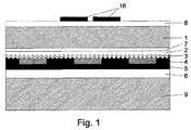
図1では、本発明によるラベルが対象物9上に接着されている。このラベルは支持基材1から成り、この支持基材は一方の表面が印刷プライマー8でコーティングされており、続いて可視モチーフ16で印刷されている。反対側の表面には最初に付着剤層7、エンボス加工された塗料層2、および半透明の金属層または屈折率の高い層3が存在している。 In FIG. 1, a label according to the invention is glued onto an
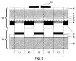
図2および図3では、ラベルを剥がすことにより不正操作の明示が誘発されている。光学特性を有する層5の一部が保護すべき対象物9上に残っており、それも正確に、剥離塗料層4が施されている領域で残っていることがはっきり認識できる。剥離塗料層4のない領域では、光学特性を有する層5が、剥がされた支持基材1およびその上に施されたホログラム上に留まっている。層5のこの「寸断」は、観察者に対し、文字、記号、シンボル、線、ギローシュ、数字、または刻印の形の光学的な不正操作の明示をもたらす。In FIG. 2 and FIG. 3,the explicit manipulation is induced by removing the label. It can be clearly recognized that a part of the
図2と図3では、個々の層の相互の付着関係の形成の詳細が異なっている。領域10〜領域13は、不正操作の明示を誘発させた際に光学的効果を可視化させる本発明による個々の層の付着関係を明確に示している。FIG. 2 and FIG. 3 differ in the details of forming the adhesion relationship between the individual layers.
図2および図3では、ラベルを剥がすことにより操作証明が誘発されている。光学特性を有する層5の一部が保護すべき対象物9上に残っており、それも正確に、剥離塗料層4が施されている領域で残っていることがはっきり認識できる。剥離塗料層4のない領域では、光学特性を有する層5が、剥がされた支持基材1およびその上に施されたホログラム上に留まっている。層5のこの「寸断」は、観察者に対し、文字、記号、シンボル、線、ギローシュ、数字、または刻印の形の光学的な操作証明をもたらす。 In FIG. 2 and FIG. 3, the operation proof is induced by removing the label. It can be clearly recognized that a part of the
図2と図3では、個々の層の相互の付着関係の形成の詳細が異なっている。領域10〜領域13は、操作証明を誘発させた際に光学的効果を可視化させる本発明による個々の層の付着関係を明確に示している。 FIG. 2 and FIG. 3 differ in the details of forming the adhesion relationship between the individual layers.
領域10では、複合体が半透明の金属層またはHRI層3と剥離塗料層4の間で剥離しており、これは層3と層4の間の付着性が、ほかのすべての層の相互の付着性および自己接着コーティング6の対象物9に対する付着性より低いことを意味している。つまり光学特性を有する層5は、領域10では自己接着コーティング6と剥離塗料層4と一緒に、保護すべき対象物9上に残っている。 In
領域11では、複合体が光学特性を有する層5と自己接着コーティング6の間で剥離しており、すなわち層5と層6の間の付着性が、ほかのすべての層の相互の付着性および自己接着コーティング6の対象物9に対する付着性より小さい。つまり光学特性を有する層5は、領域11ではエンボス塗料層2および半透明の金属層もしくはHRI層3と一緒に、剥がされた支持基材1上に残っている。 In
上記の付着関係は、必ずしも図2および図3に示したように組み合わせなくてもよく、領域10と領域13の状態の組合せまたは領域11と領域12の状態の組合せで生じてもよい。本発明によるラベルの形成に応じて、1つの特定の組合せの付着性が生じるのが好ましいが、不正操作の明示が個々に活性化するような、つまり支持基材が剥がされ、さらに領域10〜領域13のすべての示した剥離状態が1つの同じラベルで同時に生じるような、予測し得ないやり方に基づくことができる。The above adhesion relationship does not necessarily have to be combined as shown in FIG. 2 and FIG. 3, and may occur by a combination of the state of the
領域11および領域13では、不正操作の明示の誘発後に自己接着コーティング6がむきだしになり、つまり対象物上に層が残っている対象物の表面に手を触れた場合に、領域11での残留物15が接着性であることがはっきり認識できる。領域13では、自己接着コーティング6が、ラベルの剥がされた部分14上に留まっており、したがって領域13の剥がされた部分14は接着性である。つまり不正操作の明示の誘発後、ラベルまたは接着テープを再び対象物9に固定することができ、ただし光学特性を有する層5の両方の部分が再び互いにぴったり合わさるほど正確にはラベルまたは接着テープの位置決めができなくなっているので、不正操作の明示は常に視認可能である。In
上記の付着関係は、必ずしも図2および図3に示したように組み合わせなくてもよく、領域10と領域13の状態の組合せまたは領域11と領域12の状態の組合せで生じてもよい。本発明によるラベルの形成に応じて、1つの特定の組合せの付着性が生じるのが好ましいが、操作証明が個々に活性化するような、つまり支持基材が剥がされ、さらに領域10〜領域13のすべての示した剥離状態が1つの同じラベルで同時に生じるような、予測し得ないやり方に基づくことができる。 The above adhesion relationship does not necessarily have to be combined as shown in FIG. 2 and FIG. 3, and may occur by a combination of the state of the
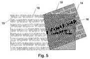
図5は、本発明によるセキュリティラベルを、一部が剥がれた状態で示しており、つまり不正操作の明示の一部が活性化された場合を示している。保護すべき対象物上にはラベルの部分15が残り、この部分15は光学特性を有する層5における凹部を、ネガ状の記号18(「VOID」)の形で有している。光学特性を有する層5のうち、ラベルの剥がされた部分14上に残っている部分は、ポジ状の記号19の形で存在している。FIG. 5 shows the security label according to the present invention in a state where a part thereof is peeled off, that is, a case wherean explicit part of theillegal operation is activated. A
図4は、本発明によるセキュリティラベル17を上面図で示しており、このラベルの見えている側には、顧客固有の印刷16が施されており、操作前の、接着されている状態である。 FIG. 4 shows a top view of a
図5は、本発明によるセキュリティラベルを、一部が剥がれた状態で示しており、つまり操作証明の一部が活性化された場合を示している。保護すべき対象物上にはラベルの部分15が残り、この部分15は光学特性を有する層5における凹部を、ネガ状の記号18(「VOID」)の形で有している。光学特性を有する層5のうち、ラベルの剥がされた部分14上に残っている部分は、ポジ状の記号19の形で存在している。 FIG. 5 shows the security label according to the present invention in a partially peeled state, that is, a case where a part of the operation certificate is activated. A
構成例1(印刷可能なセキュリティラベル) Configuration example 1 (printable security label)

1 支持基材
2 光学活性構造(例えばホログラム)を有する塗料層
3 半透明の金属層またはHRI層
4 部分的な剥離塗料層
5 光学特性を有する層
6 自己接着コーティング
7 (任意選択の)付着剤層
8 (任意選択の)印刷プライマー層
9 上にラベルまたは接着テープが施された対象物
10、11、12、13 様々な付着関係を有する領域
14 ラベルのうち支持基材1と共に剥がれた部分
15 ラベルのうち保護すべき対象物9上に残った部分
16 顧客固有の印刷
17 本発明によるセキュリティラベル
18 光学特性を有する層5のうち保護すべき対象物9に残っており、記号の形のネガ状の凹部を有する部分
19 光学特性を有する層5のうちポジ状の記号の形で支持基材1と共に剥がれた部分DESCRIPTION OF SYMBOLS 1
Claims (17)
Translated fromJapanesea)表面構造を有する塗料層2
b)半透明の金属層もしくは屈折率の高い層3
c)文字、記号、シンボル、線、ギローシュ、数字、または刻印の形の部分的な剥離塗料層4
d)1つまたは複数の光学特性を有する塗料層5
e)自己接着コーティング6
が施されており、
剥離塗料層4でコーティングされていない領域では、すべての層の相互の付着性および層6の保護すべき対象物に対する付着性が、層5の層6に対する付着性より大きく、またはすべての層の相互の付着性が、層6の保護すべき対象物9に対する付着性より大きく、かつ剥離塗料層4でコーティングされている領域では、すべての層の相互の付着性および層6の保護すべき対象物9に対する付着性が、層3の層4に対する付着性または層4の層5に対する付着性より大きく、
前記塗料層2が支持基材1上に施され、前記層3が前記塗料層2上に施され、
前記剥離塗料層4が、塩素化ポリオレフィンもしくはポリアクリレートコポリマーを含み、シクロオレフィンコポリマーベースの、ニトロセルロースベースの、アクリレートベースの、ポリ塩化ビニルベースの、エチレンアクリレートコポリマーベースの、もしくはスチレンアクリレートベースの塗料組成を含む
ことを特徴とするセキュリティラベルまたはセキュリティ接着テープ。In a security label or security adhesive tape with atampering indication provided with a flexible support substrate 1 based on a flexible plastic film, it has the following layers on one surface of the support substrate: a)surface structure Paint layer 2
b) Translucent metal layer or high refractive index layer 3
c) Partial release paint layer 4 in the form of letters, symbols, symbols, lines, guilloche, numbers or inscriptions
d) Paint layer 5having one or more optical properties
e) Self-adhesive coating 6
Is given,
In areas not coated with the release paint layer 4, the adhesion of all layers to each other and the adhesion of the layer 6 to the object to be protected is greater than the adhesion of the layer 5 to the layer 6 or of all the layers. In an area where the mutual adhesion is greater than the adhesion of the layer 6 to the object 9 to be protected and is coated with the release paint layer 4, the mutual adhesion of all layers and the object to be protected of the layer 6 adhesion to objects 9,rather greater than adhesion to the layer 5 of the sticky or layer 4 to layer 4 of the layer3,
The paint layer 2 is applied on the support substrate 1, the layer 3 is applied on the paint layer 2,
The release coating layer 4 comprises a chlorinated polyolefin or polyacrylate copolymer, a cycloolefin copolymer based, a nitrocellulose based, an acrylate based, a polyvinyl chloride based, an ethylene acrylate copolymer based or a styrene acrylate based coating. A security label or security adhesive tapecomprising a composition .
Applications Claiming Priority (3)
| Application Number | Priority Date | Filing Date | Title |
|---|---|---|---|
| ATA1357/2010 | 2010-08-13 | ||
| ATA1357/2010AAT510505B1 (en) | 2010-08-13 | 2010-08-13 | SAFETY LABEL WITH MANIPULATION DETECTION |
| PCT/EP2011/003834WO2012019722A1 (en) | 2010-08-13 | 2011-07-30 | Security label or adhesive tape with evidence of tampering |
Publications (2)
| Publication Number | Publication Date |
|---|---|
| JP2013536465A JP2013536465A (en) | 2013-09-19 |
| JP5901027B2true JP5901027B2 (en) | 2016-04-06 |
Family
ID=44653231
Family Applications (1)
| Application Number | Title | Priority Date | Filing Date |
|---|---|---|---|
| JP2013523517AExpired - Fee RelatedJP5901027B2 (en) | 2010-08-13 | 2011-07-30 | Security label or security adhesive tape with explicit manipulation |
Country Status (11)
| Country | Link |
|---|---|
| US (1) | US20130134698A1 (en) |
| EP (1) | EP2603911B1 (en) |
| JP (1) | JP5901027B2 (en) |
| KR (1) | KR20130108292A (en) |
| CN (1) | CN103493118B (en) |
| AT (1) | AT510505B1 (en) |
| ES (1) | ES2821439T3 (en) |
| MX (1) | MX2013001778A (en) |
| PL (1) | PL2603911T3 (en) |
| UA (1) | UA110798C2 (en) |
| WO (1) | WO2012019722A1 (en) |
Families Citing this family (23)
| Publication number | Priority date | Publication date | Assignee | Title |
|---|---|---|---|---|
| CN103717387B (en) | 2011-08-03 | 2017-11-07 | 印刷包装国际公司 | Systems and methods for forming laminates with patterned microwave energy interacting materials |
| CN103325298A (en)* | 2012-03-23 | 2013-09-25 | 东莞市安力华印刷有限公司 | Anti-counterfeiting label and anti-counterfeiting verification system for small batch retail products |
| DE102013108906A1 (en)* | 2013-08-19 | 2015-02-19 | Ovd Kinegram Ag | System and method for producing an individualized security element |
| EP2851194B1 (en)* | 2013-09-20 | 2015-12-16 | Hueck Folien Ges.m.b.H | Safety element, in particular safety label |
| EP3049248B1 (en) | 2013-09-26 | 2018-11-07 | Graphic Packaging International, LLC | Laminates, and systems and methods for laminating |
| JP6081959B2 (en)* | 2014-05-19 | 2017-02-15 | ダイセルバリューコーティング株式会社 | Resin film, laminate, method for producing the same, and method for producing fuel cell |
| US10318962B2 (en) | 2014-11-17 | 2019-06-11 | Amazon Technologies, Inc. | Authenticity label for items |
| US10102532B2 (en)* | 2014-11-17 | 2018-10-16 | Amazon Technologies, Inc. | Tracking and verifying authenticity of items |
| MX384916B (en) | 2014-12-22 | 2025-03-14 | Graphic Packaging Int Llc | SYSTEMS AND METHODS FOR FORMING LAMINATES. |
| JP2016131830A (en)* | 2015-01-22 | 2016-07-25 | 株式会社三共 | Game machine |
| EP3106561B1 (en) | 2015-06-19 | 2025-06-04 | Hueck Folien Gesellschaft m.b.H. | Safety label with manipulation verification |
| DE102015112909B3 (en)* | 2015-08-05 | 2017-02-09 | Leonhard Kurz Stiftung & Co. Kg | Method and device for producing a multilayer film |
| US10144197B2 (en)* | 2015-08-05 | 2018-12-04 | John Kent Lee | Precious metal sheet display and method of manufacturing |
| US20190138778A1 (en)* | 2016-03-11 | 2019-05-09 | Bilcare Limited | A system for product authentication and method thereof |
| EP3305541B1 (en)* | 2016-10-04 | 2020-01-15 | Hueck Folien Gesellschaft m.b.H. | Security element and valuable document with this security element |
| WO2019067928A2 (en)* | 2017-09-29 | 2019-04-04 | Nike Innovate C.V. | Structurally-colored articles and methods of making and using structurally-colored articles |
| DE102018102734A1 (en)* | 2018-01-18 | 2019-07-18 | Schreiner Group Gmbh & Co. Kg | Flexible electrical circuit with connection between electrically conductive structural elements |
| EP3726507B1 (en) | 2019-04-19 | 2021-05-26 | Securikett Ulrich & Horn GmbH | Sealing film |
| AT523745B1 (en)* | 2020-05-12 | 2022-08-15 | Hueck Folien Gmbh | SECURITY ELEMENT |
| DE102021001588A1 (en)* | 2021-03-25 | 2022-09-29 | Giesecke+Devrient Currency Technology Gmbh | Manufacturing process for an optically variable security element |
| DE102021001589A1 (en)* | 2021-03-25 | 2022-09-29 | Giesecke+Devrient Currency Technology Gmbh | Manufacturing process for an optically variable security element |
| RU210499U1 (en)* | 2021-08-30 | 2022-04-18 | Акционерное общество "Гознак" (АО "Гознак") | MULTILAYER SELF-ADHESIVE FILM STRUCTURE |
| EP4145426B1 (en) | 2021-09-01 | 2024-10-30 | Hueck Folien Gesellschaft m.b.H. | Security label |
Family Cites Families (26)
| Publication number | Priority date | Publication date | Assignee | Title |
|---|---|---|---|---|
| JPS5258695A (en)* | 1975-11-10 | 1977-05-14 | Sanyo Shiki Kk | Material for liquid container made of paper |
| CH661368A5 (en)* | 1984-01-03 | 1987-07-15 | Landis & Gyr Ag | Diffraction optical safety element. |
| GB2173150B (en)* | 1985-03-28 | 1989-06-21 | Daimatsu Kagaku Kogyo Kk | An easily breakable sticking material |
| CH680170A5 (en)* | 1991-05-03 | 1992-06-30 | Landis & Gyr Betriebs Ag | Diffraction structure identification label - has pattern formed in semiconductor reflective material in laminated component |
| DE4130550A1 (en)* | 1991-09-13 | 1993-03-18 | Inst Neue Mat Gemein Gmbh | OPTICAL ELEMENTS AND METHOD FOR THE PRODUCTION THEREOF |
| CA2134521A1 (en)* | 1993-11-02 | 1995-05-03 | Raymond R. Gosselin | Tamper-indicating label |
| JPH08152842A (en)* | 1994-03-31 | 1996-06-11 | Toppan Printing Co Ltd | Hologram brittle seal |
| DE4415426A1 (en)* | 1994-05-03 | 1995-11-09 | Ucb Helio Folien Gmbh | Laminated plastic film for packaging and use of packaging |
| US6280891B2 (en)* | 1994-05-04 | 2001-08-28 | Hologram Industries S.A. | Multi-layer assembly and method for marking articles and resulting marked articles |
| CA2194454A1 (en)* | 1994-07-08 | 1996-01-25 | Minnesota Mining And Manufacturing Company | Transparent multilayer film and its use for protection of data on documents as well as a tamper-proof label |
| US5683774A (en)* | 1994-12-09 | 1997-11-04 | Minnesota Mining And Manufacturing Company | Durable, tamper resistant security laminate |
| US5510171A (en)* | 1995-01-19 | 1996-04-23 | Minnesota Mining And Manufacturing Company | Durable security laminate with hologram |
| US5633058A (en)* | 1995-09-05 | 1997-05-27 | Hoffer; Erik | Message-indicating self-wound tape and method of making same |
| JPH09114383A (en)* | 1995-10-19 | 1997-05-02 | Lintec Corp | Tacky adhesive sheet for forming label affixing part |
| DE20015840U1 (en)* | 1999-09-23 | 2001-02-08 | topac MultimediaPrint GmbH, 33332 Gütersloh | Fuse element and foil with dielectric layer |
| GB0013379D0 (en)* | 2000-06-01 | 2000-07-26 | Optaglio Ltd | Label and method of forming the same |
| JP4565482B2 (en)* | 2001-05-30 | 2010-10-20 | 大日本印刷株式会社 | Hologram laminate and hologram label |
| AT502139A1 (en) | 2001-11-09 | 2007-01-15 | Hueck Folien Gmbh | RAIL-MATERIAL MATERIALS WITH SURFACE STRUCTURE, METHOD FOR THE PRODUCTION THEREOF AND THEIR USE |
| DE102004041434B4 (en)* | 2004-08-27 | 2013-10-10 | Credit Card Supplies | Method for producing a embossing plate for a hot-cold laminating press with three-dimensional structures |
| JP2007178558A (en)* | 2005-12-27 | 2007-07-12 | Dainippon Ink & Chem Inc | Adhesive sheet with peeling detection function |
| US20090322538A1 (en)* | 2006-04-20 | 2009-12-31 | Dunmore Corporation | Tamper evident security film |
| KR100795625B1 (en) | 2006-09-13 | 2008-01-17 | 한국조폐공사 | Anti-falsification hologram film added with fluorescent substance and its manufacturing method |
| WO2008118135A2 (en)* | 2006-10-03 | 2008-10-02 | Jds Uniphase Corporation | Tamper evident and resisting informational article and method of producing same |
| ES2354576T3 (en) | 2007-03-21 | 2011-03-16 | Hueck Folien Ges.M.B.H. | SECURITY FILM WITH HANDLING DETECTION. |
| EP2130884A1 (en)* | 2008-06-02 | 2009-12-09 | Hueck Folien Ges.m.b.H. | Safety sticker or adhesive band |
| PL2267686T3 (en)* | 2009-05-07 | 2014-04-30 | Hueck Folien Gmbh | Safety label with authenticity and manipulation evidence |
- 2010
- 2010-08-13ATATA1357/2010Apatent/AT510505B1/ennot_activeIP Right Cessation
- 2011
- 2011-07-30USUS13/812,641patent/US20130134698A1/ennot_activeAbandoned
- 2011-07-30MXMX2013001778Apatent/MX2013001778A/ennot_activeApplication Discontinuation
- 2011-07-30UAUAA201303042Apatent/UA110798C2/enunknown
- 2011-07-30JPJP2013523517Apatent/JP5901027B2/ennot_activeExpired - Fee Related
- 2011-07-30EPEP11757750.2Apatent/EP2603911B1/enactiveActive
- 2011-07-30CNCN201180038992.1Apatent/CN103493118B/ennot_activeExpired - Fee Related
- 2011-07-30KRKR1020137006239Apatent/KR20130108292A/ennot_activeCeased
- 2011-07-30PLPL11757750Tpatent/PL2603911T3/enunknown
- 2011-07-30WOPCT/EP2011/003834patent/WO2012019722A1/enactiveApplication Filing
- 2011-07-30ESES11757750Tpatent/ES2821439T3/enactiveActive
Also Published As
| Publication number | Publication date |
|---|---|
| MX2013001778A (en) | 2013-04-03 |
| CN103493118B (en) | 2016-08-31 |
| KR20130108292A (en) | 2013-10-02 |
| UA110798C2 (en) | 2016-02-25 |
| PL2603911T3 (en) | 2020-11-16 |
| CN103493118A (en) | 2014-01-01 |
| RU2013110837A (en) | 2014-09-20 |
| US20130134698A1 (en) | 2013-05-30 |
| ES2821439T3 (en) | 2021-04-26 |
| JP2013536465A (en) | 2013-09-19 |
| AT510505A1 (en) | 2012-04-15 |
| AT510505B1 (en) | 2013-02-15 |
| WO2012019722A1 (en) | 2012-02-16 |
| EP2603911B1 (en) | 2020-05-27 |
| EP2603911A1 (en) | 2013-06-19 |
Similar Documents
| Publication | Publication Date | Title |
|---|---|---|
| JP5901027B2 (en) | Security label or security adhesive tape with explicit manipulation | |
| JP5924824B2 (en) | Security label or security adhesive tape with operation certificate | |
| JP5686495B2 (en) | Security device incorporating optically variable adhesive | |
| JP6431902B2 (en) | Security elements, especially security labels | |
| EP1972674B1 (en) | Safety film with manipulation verification | |
| CN101070040A (en) | A security device formed by a hologram and a color shifting ink | |
| JP2008139719A (en) | Hologram label | |
| CN102272811B (en) | Secure elements, especially secure elements with manipulation authentication | |
| RU2523255C2 (en) | Safety label provided with system of authenticity confirmation and detection of manipulations | |
| RU2575423C2 (en) | Protective label or adhesive tape with manipulation indication | |
| EP2130884A1 (en) | Safety sticker or adhesive band | |
| JP4967566B2 (en) | Transfer sheet | |
| CN114419984A (en) | Colorful holographic anti-counterfeiting mark film and preparation method thereof | |
| JP2002366038A (en) | OVD seal, method of manufacturing the same, and method of attaching the same | |
| JP6175895B2 (en) | Fraud detection label | |
| TWI398386B (en) | Color polyester film having property for prevention of damages on patterns or characters thereof and process for the same | |
| CN120418850A (en) | Planar sealing element | |
| JP6307817B2 (en) | Fraud detection labels and labeled items | |
| JP5304109B2 (en) | Display body and expression method of optical effect function | |
| JP2011022236A (en) | Re-sticking prevention sticker |
Legal Events
| Date | Code | Title | Description |
|---|---|---|---|
| A621 | Written request for application examination | Free format text:JAPANESE INTERMEDIATE CODE: A621 Effective date:20140619 | |
| A977 | Report on retrieval | Free format text:JAPANESE INTERMEDIATE CODE: A971007 Effective date:20150831 | |
| A131 | Notification of reasons for refusal | Free format text:JAPANESE INTERMEDIATE CODE: A131 Effective date:20150916 | |
| A601 | Written request for extension of time | Free format text:JAPANESE INTERMEDIATE CODE: A601 Effective date:20151210 | |
| A521 | Request for written amendment filed | Free format text:JAPANESE INTERMEDIATE CODE: A523 Effective date:20160114 | |
| TRDD | Decision of grant or rejection written | ||
| A01 | Written decision to grant a patent or to grant a registration (utility model) | Free format text:JAPANESE INTERMEDIATE CODE: A01 Effective date:20160302 | |
| A61 | First payment of annual fees (during grant procedure) | Free format text:JAPANESE INTERMEDIATE CODE: A61 Effective date:20160304 | |
| R150 | Certificate of patent or registration of utility model | Ref document number:5901027 Country of ref document:JP Free format text:JAPANESE INTERMEDIATE CODE: R150 | |
| LAPS | Cancellation because of no payment of annual fees |