JP5900950B2 - Wavelength scanning optical coherence tomography and its phase stabilization program - Google Patents
Wavelength scanning optical coherence tomography and its phase stabilization programDownload PDFInfo
- Publication number
- JP5900950B2 JP5900950B2JP2012000313AJP2012000313AJP5900950B2JP 5900950 B2JP5900950 B2JP 5900950B2JP 2012000313 AJP2012000313 AJP 2012000313AJP 2012000313 AJP2012000313 AJP 2012000313AJP 5900950 B2JP5900950 B2JP 5900950B2
- Authority
- JP
- Japan
- Prior art keywords
- interference signal
- spectrum
- phase
- spectral
- oct
- Prior art date
- Legal status (The legal status is an assumption and is not a legal conclusion. Google has not performed a legal analysis and makes no representation as to the accuracy of the status listed.)
- Active
Links
Images


Classifications
- G—PHYSICS
- G01—MEASURING; TESTING
- G01B—MEASURING LENGTH, THICKNESS OR SIMILAR LINEAR DIMENSIONS; MEASURING ANGLES; MEASURING AREAS; MEASURING IRREGULARITIES OF SURFACES OR CONTOURS
- G01B9/00—Measuring instruments characterised by the use of optical techniques
- G01B9/02—Interferometers
- G01B9/02055—Reduction or prevention of errors; Testing; Calibration
- G01B9/02075—Reduction or prevention of errors; Testing; Calibration of particular errors
- A—HUMAN NECESSITIES
- A61—MEDICAL OR VETERINARY SCIENCE; HYGIENE
- A61B—DIAGNOSIS; SURGERY; IDENTIFICATION
- A61B3/00—Apparatus for testing the eyes; Instruments for examining the eyes
- A61B3/10—Objective types, i.e. instruments for examining the eyes independent of the patients' perceptions or reactions
- A61B3/102—Objective types, i.e. instruments for examining the eyes independent of the patients' perceptions or reactions for optical coherence tomography [OCT]
- G—PHYSICS
- G01—MEASURING; TESTING
- G01B—MEASURING LENGTH, THICKNESS OR SIMILAR LINEAR DIMENSIONS; MEASURING ANGLES; MEASURING AREAS; MEASURING IRREGULARITIES OF SURFACES OR CONTOURS
- G01B9/00—Measuring instruments characterised by the use of optical techniques
- G01B9/02—Interferometers
- G01B9/02001—Interferometers characterised by controlling or generating intrinsic radiation properties
- G—PHYSICS
- G01—MEASURING; TESTING
- G01B—MEASURING LENGTH, THICKNESS OR SIMILAR LINEAR DIMENSIONS; MEASURING ANGLES; MEASURING AREAS; MEASURING IRREGULARITIES OF SURFACES OR CONTOURS
- G01B9/00—Measuring instruments characterised by the use of optical techniques
- G01B9/02—Interferometers
- G01B9/02083—Interferometers characterised by particular signal processing and presentation
- G—PHYSICS
- G01—MEASURING; TESTING
- G01B—MEASURING LENGTH, THICKNESS OR SIMILAR LINEAR DIMENSIONS; MEASURING ANGLES; MEASURING AREAS; MEASURING IRREGULARITIES OF SURFACES OR CONTOURS
- G01B9/00—Measuring instruments characterised by the use of optical techniques
- G01B9/02—Interferometers
- G01B9/0209—Low-coherence interferometers
- G01B9/02091—Tomographic interferometers, e.g. based on optical coherence
- G—PHYSICS
- G01—MEASURING; TESTING
- G01N—INVESTIGATING OR ANALYSING MATERIALS BY DETERMINING THEIR CHEMICAL OR PHYSICAL PROPERTIES
- G01N21/00—Investigating or analysing materials by the use of optical means, i.e. using sub-millimetre waves, infrared, visible or ultraviolet light
- G01N21/17—Systems in which incident light is modified in accordance with the properties of the material investigated
- G01N21/25—Colour; Spectral properties, i.e. comparison of effect of material on the light at two or more different wavelengths or wavelength bands
- G01N21/31—Investigating relative effect of material at wavelengths characteristic of specific elements or molecules, e.g. atomic absorption spectrometry
- G—PHYSICS
- G01—MEASURING; TESTING
- G01N—INVESTIGATING OR ANALYSING MATERIALS BY DETERMINING THEIR CHEMICAL OR PHYSICAL PROPERTIES
- G01N21/00—Investigating or analysing materials by the use of optical means, i.e. using sub-millimetre waves, infrared, visible or ultraviolet light
- G01N21/17—Systems in which incident light is modified in accordance with the properties of the material investigated
- G01N21/47—Scattering, i.e. diffuse reflection
- G01N21/4795—Scattering, i.e. diffuse reflection spatially resolved investigating of object in scattering medium
Landscapes
- Physics & Mathematics (AREA)
- Health & Medical Sciences (AREA)
- Life Sciences & Earth Sciences (AREA)
- General Physics & Mathematics (AREA)
- General Health & Medical Sciences (AREA)
- Spectroscopy & Molecular Physics (AREA)
- Chemical & Material Sciences (AREA)
- Analytical Chemistry (AREA)
- Biochemistry (AREA)
- Immunology (AREA)
- Pathology (AREA)
- Nuclear Medicine, Radiotherapy & Molecular Imaging (AREA)
- Radiology & Medical Imaging (AREA)
- Engineering & Computer Science (AREA)
- Medical Informatics (AREA)
- Molecular Biology (AREA)
- Biophysics (AREA)
- Ophthalmology & Optometry (AREA)
- Biomedical Technology (AREA)
- Heart & Thoracic Surgery (AREA)
- Veterinary Medicine (AREA)
- Optics & Photonics (AREA)
- Surgery (AREA)
- Animal Behavior & Ethology (AREA)
- Public Health (AREA)
- Signal Processing (AREA)
- Investigating Or Analysing Materials By Optical Means (AREA)
- Eye Examination Apparatus (AREA)
Description
Translated fromJapanese本発明は、光源の波長を走査してスペクトル干渉信号を得る波長走査型光干渉断層計(Swept Source Optical Coherence Tomography、略して「SS−OCT」という。)及びその位相安定化プログラムに関し、特に、追加的なハードウェアを使用せず、一般的に用いられているSS−OCTと同じ構成のみにより位相を安定化させる技術に関する。 The present invention relates to a wavelength scanning optical coherence tomography (Swept Source Optical Coherence Tomography, abbreviated as “SS-OCT”) and a phase stabilization program thereof, which scan a wavelength of a light source to obtain a spectral interference signal. The present invention relates to a technique for stabilizing the phase by using only the same configuration as that of SS-OCT that is generally used without using additional hardware.
従来、医療分野等で用いられる非破壊断層計測技術の1つとして、時間的に低コヒーレンスな光をプローブ(探針)として用いる光断層画像化法「光コヒーレンストモグラフィー」(OCT)がある(特許文献1参照)。OCTは、光を計測プローブとして用いるため、被計測物体の屈折率分布、分光情報、偏光情報(複屈折率分布)等が計測できるという利点がある。 Conventionally, as one of the non-destructive tomographic techniques used in the medical field etc., there is an optical tomographic imaging method “optical coherence tomography” (OCT) using temporally low coherence light as a probe (patent) (patent) Reference 1). Since OCT uses light as a measurement probe, it has the advantage that it can measure the refractive index distribution, spectral information, polarization information (birefringence distribution), etc. of the measured object.
基本的なOCT43は、マイケルソン干渉計を基本としており、その原理を図3で説明する。光源44から射出された光は、コリメートレンズ45で平行化された後に、ビームスプリッター46により参照光と物体光に分割される。物体光は、物体アーム内の対物レンズ47によって被計測物体48に集光され、そこで散乱・反射された後に再び対物レンズ47、ビームスプリッター46に戻る。 The
一方、参照光は参照アーム内の対物レンズ49を通過した後に参照鏡50によって反射され、再び対物レンズ49を通してビームスプリッター46に戻る。このようにビームスプリッター46に戻った物体光と参照光は、物体光とともに集光レンズ51に入射し光検出器52(フォトダイオード等)に集光される。 On the other hand, the reference light passes through the
OCTの光源44は、時間的に低コヒーレンスな光(異なった時刻に光源から出た光同士は極めて干渉しにくい光)の光源を利用する。時間的低コヒーレンス光を光源としたマイケルソン型の干渉計では、参照アームと物体アームの距離がほぼ等しいときにのみ干渉信号が現れる。この結果、参照アームと物体アームの光路長差(τ)を変化させながら、光検出器52で干渉信号の強度を計測すると、光路長差に対する干渉信号(インターフェログラム)が得られる。 The
そのインターフェログラムの形状が、被計測物体48の奥行き方向の反射率分布を示しており、1次元の軸方向走査により被計測物体48の奥行き方向の構造を得ることができる。このように、OCT43では、光路長走査により、被計測物体48の奥行き方向の構造を計測できる。 The shape of the interferogram shows the reflectance distribution in the depth direction of the
このような軸方向の走査のほかに、横方向の機械的走査を加え、2次元の走査を行うことで被計測物体の2次元断面画像が得られる。この横方向の走査を行う走査装置としては、被計測物体を直接移動させる構成、物体は固定したままで対物レンズをシフトさせる構成、被計測物体も対物レンズも固定したままで、対物レンズの瞳面付近においたガルバノミラーの角度を回転させる構成等が用いられている。 In addition to the scanning in the axial direction, a two-dimensional cross-sectional image of the object to be measured can be obtained by performing a two-dimensional scanning by adding a horizontal mechanical scanning. The scanning device that performs the horizontal scanning includes a configuration in which the object to be measured is directly moved, a configuration in which the objective lens is shifted while the object is fixed, and a pupil of the objective lens while the object to be measured and the objective lens are fixed. The structure etc. which rotate the angle of the galvanometer mirror in the surface vicinity are used.
以上の基本的なOCTが発展したものとして、分光器を用いてスペクトル信号を得るスペクトルドメインOCT(SD−OCT)と、光源の波長を走査してスペクトル干渉信号を得る波長走査型OCT(Swept Source OCT、略して「SS−OCT」という。)がある。SD−OCTには、フーリエドメインOCT(Fourier Domain OCT、略して「FD−OCT」という。特許文献2参照)、及び偏光感受型OCT(Polarization-Sensitive OCT、略して「PS−OCT」という。特許文献3参照)がある。 As the development of the basic OCT described above, a spectral domain OCT (SD-OCT) that obtains a spectrum signal using a spectroscope, and a wavelength scanning OCT (Swept Source) that obtains a spectrum interference signal by scanning the wavelength of the light source. OCT, abbreviated as “SS-OCT”). SD-OCT includes Fourier domain OCT (Fourier Domain OCT, abbreviated as “FD-OCT”; see Patent Document 2), and polarization-sensitive OCT (Polarization-Sensitive OCT, abbreviated as “PS-OCT”). Reference 3).
FD−OCTは、被計測物体からの反射光の波長スペクトルを、スペクトロメーター(スペクトル分光器)で取得し、このスペクトル強度分布に対してフーリエ変換することで、実空間(OCT信号空間)上での信号を取り出すことを特徴とするものであり、このFD−OCTは、奥行き方向の走査を行う必要がなく、x軸方向の走査を行うことで被計測物体の断面構造を計測可能である。 FD-OCT obtains the wavelength spectrum of the reflected light from the object to be measured with a spectrometer (spectrum spectrometer), and performs Fourier transform on the spectrum intensity distribution, thereby realizing the real space (OCT signal space). This FD-OCT does not need to scan in the depth direction, and can measure the cross-sectional structure of the object to be measured by scanning in the x-axis direction.
SS−OCTは、高速波長スキャニングレーザーにより光源の波長を変え、スペクトル信号と同期取得された光源走査信号を用いて干渉信号を最配列し、信号処理を加えることで3次元光断層画像を得るものである。なお、光源の波長を変える手段として、モノクロメーターを利用したものでも、SS−OCTとして利用可能である。 SS-OCT obtains a three-dimensional optical tomographic image by changing the wavelength of the light source using a high-speed wavelength scanning laser, rearranging interference signals using a light source scanning signal acquired in synchronization with a spectrum signal, and applying signal processing. It is. As a means for changing the wavelength of the light source, a device using a monochromator can be used as SS-OCT.
ドップラー光コヒーレンストモグラフィー(ドップラーOCT)による、網膜の血流の分布の計測が知られている。これは、上記FD−OCT等を用いて、網膜の血流の分布が計測を行うことのできる手段であり、同様に、スペクトルドメインOCTを使うことによって、横断面網膜血流画像形成が得られ、また次元の網膜の脈管構造も観察することができる。 Measurement of blood flow distribution in the retina by Doppler optical coherence tomography (Doppler OCT) is known. This is a means by which the retinal blood flow distribution can be measured using the FD-OCT or the like, and similarly, the cross-sectional retinal blood flow image formation can be obtained by using the spectral domain OCT. Also, the vascular structure of the retina can be observed.
本発明者らは、従来よりドップラーOCTに着目し、生体内、特に眼底の血流を非侵襲で計測する手法の研究・開発を行って来た。従来本発明者らはSD−OCTを技術基盤上にドップラーOCTを実装し、眼底血流検査に成功してきたが、近年OCTの技術基板はSD−OCTから、次世代であるSS−OCTに移行しつつある。 The inventors of the present invention have focused on Doppler OCT and have been researching and developing techniques for measuring blood flow in a living body, particularly in the fundus, in a non-invasive manner. Conventionally, the present inventors have mounted SD-OCT on the technology base and succeeded in fundus blood flow examination, but in recent years, the OCT technology substrate has moved from SD-OCT to the next generation SS-OCT. I am doing.
本発明者らはSS−OCTによってもドップラー計測の研究開発を行ってきたが、ドップラー計測には、困難な問題がある。これは、SS−OCT特有の位相不安定性に起因するものである。 The present inventors have conducted research and development of Doppler measurement also by SS-OCT, but Doppler measurement has a difficult problem. This is due to the phase instability peculiar to SS-OCT.
SS−OCTの位相不安定性を補正する方法は Harvard Medical School により提案されているものの(非特許文献1参照)、この技術は、複雑なハードウェアを必要とし製品のコストの増大がさけられない。 Although a method for correcting the phase instability of SS-OCT has been proposed by Harvard Medical School (see Non-Patent Document 1), this technique requires complex hardware and cannot increase the cost of the product.
本発明は、上記SS−OCTの位相不安定性の問題を解決することを目的とするものであり、従来同様の標準的なSS−OCTの構成のみを前提とし、そこから得られる信号を適切に処理することで高い位相の安定性を得ることを課題とするものであり、これにより、従来のSS−OCTを利用して、SS−OCTによる計測及びドップラー計測を実現しようとするものである。 The present invention aims to solve the above-mentioned problem of phase instability of SS-OCT, and presupposes only a standard SS-OCT configuration similar to the conventional one, and appropriately obtains signals obtained therefrom. It is an object to obtain a high phase stability by processing, and thereby attempts to realize SS-OCT measurement and Doppler measurement using conventional SS-OCT.
本発明は上記課題を解決するために、SS−OCTにおいて、波長走査型光源から出射されて分割され、固定参照鏡で反射された参照光と、被計測物体で反射された物体光とが重ねられて光検知器で検出されたスペクトル干渉信号に基づき、断層画像を生成するコンピュータを、スペクトル干渉信号の位相データを補正する補正手段として機能させるSS−OCTのスペクトル干渉信号の位相を安定化するプログラムであって、前記補正手段は、隣接する2つのA−スキャンにおいて、基準となる第1のA−スキャンのスペクトル干渉信号S1(j)と、第2のA−スキャンのスペクトル干渉信号であってジッターによるスペクトルシフトβを受けたスペクトル干渉信号S’2(j)とから、下記の式(2’)に従い、スペクトルシフトβを求め、このスペクトルシフトβを消去することにより、スペクトル干渉信号の位相データの補正を行うことを特徴とするSS−OCTの位相を安定化するプログラムを提供する。
Angle[F[S’2(j)](ζ)F[S1*(j)](ζ)]=−2πζβ/N・・・(2’)
但し、jはスペクトルのサンプリング点、即ちA−スキャンにおける深さ方向(光軸方向)の座標であり、Nはサンプリング点数であり、ζは被計測物体の深さを示す変数でζ=0,1,・・・・N−1であり、F[ ]は[ ]内をフーリエ変換した式であり、Angle[]は[]内の位相を表す式であり、* は複素共約を示す。In order to solve the above-described problems, the present invention provides an SS-OCT in which reference light emitted from a wavelength scanning light source and divided and reflected by a fixed reference mirror is overlapped with object light reflected by an object to be measured. The phase of the SS-OCT spectrum interference signal is stabilized by causing a computer that generates a tomographic image based on the spectrum interference signal detected by the photodetector to function as correction means for correcting the phase data of the spectrum interference signal. In the program, the correction means uses a first A-scan spectrum interference signal S1 (j) as a reference and a second A-scan spectrum interference signal in two adjacent A-scans. 'since the2 (j), the following equation (2' there are spectral interference signal S that has received the spectral shift β by jitterfollow), determined the spectrum shift β Because, by erasing the spectral shift beta, provides a program for stabilizing the phase of the SS-OCT, characterized in that correcting the phase data of spectral interference signal.
Angle [F [S ′2(j)] (ζ) F [S1*(j)] (ζ)] = − 2πζβ / N (2 ′)
Wherej is a sampling point of the spectrum, that is, coordinates in the depth direction (optical axis direction) in the A-scan, N is the number of sampling points, ζ is a variable indicating the depth of the object to be measured, and ζ = 0, 1,..., N−1, F [] is an expression obtained by Fourier transform in [], Angle [] is an expression representing a phase in [], and* indicates a complex co-agreement.
本発明は上記課題を解決するために、SS−OCTにおいて、波長走査型光源から出射されて分割され、固定参照鏡で反射された参照光と、被計測物体で反射された物体光とが重ねられて光検知器で検出されたスペクトル干渉信号に基づき、断層画像を生成するコンピュータを、スペクトル干渉信号の位相データを補正する第1の補正手段と第2の補正手段として順次機能させるSS−OCTのスペクトル干渉信号の位相を安定化するプログラムであって、前記第1の補正手段は、隣接する2つのA−スキャンにおいて、基準となる第1のA−スキャンのスペクトル干渉信号S1(j)と、第2のA−スキャンのスペクトル干渉信号であってジッターによるスペクトルシフトβを受けたスペクトル干渉信号S’2(j)とから、下記の式(2’)に従い、スペクトルシフトβを求め、このスペクトルシフトβを消去することにより、スペクトル干渉信号の位相データの補正を行い、前記第2の補正手段は、前記2つのA−スキャンで得られたスペクトル干渉信号に係るドップラー位相シフトを示す下記の式(9)において、ドップラー信号vz(ζ)がない領域における、ζの切片bm=4πτvb/λC、傾きam=−2πβ’/Nの1次関数について、下記の式(10)に示す誤差エネルギーを最小とする傾きamと切片bmを求めることで、バルクモーション及びジッターによるスペクトルシフトβの残差β’を求めて、スペクトル干渉信号の位相データの補正を行うことを特徴とするSS−OCTの位相を安定化するプログラムを提供する。
Angle[F[S’2(j)](ζ)F[S1*(j)](ζ)]=−2πζβ/N ・・・(2’)
但し、jはスペクトルのサンプリング点、即ちA−スキャンにおける深さ方向(光軸方向)の座標であり、Nはサンプリング点数であり、ζは被計測物体の深さを示す変数でζ=0,1,・・・・N−1であり、F[ ]は[ ]内をフーリエ変換した式であり、Angle[]は[]内の位相を表す式であり、* は複素共約を示す。
Δφ(ζ)=(4πτ/λC)nvz(ζ)+(4πτ/λC)vb −2πζβ’/N
・・・(9)
但し、τは2つのA−スキャン間の時間、λC は光源の中心波長、nは屈折率、変数ζの関数vz(ζ)は光軸方向の速度、vbはバルクモーションの速度、β’はジッターによるスペクトルシフトの残差、Nはサンプリング点数、ζの関数vz(ζ)は光軸方向の速度、ζは被計測物体の深さを示す変数をそれぞれ示し、ζ=0,1,・・・・N−1である。
R22=ΣζWm(ζ)[Δφ(ζ)−(amζ+bm)]2 ・・・(10)
但し、m=0,1,2…… であり、ζは被計測物体の深さを示す変数であり、Wm(ζ)は重みである。In order to solve the above-described problems, the present invention provides an SS-OCT in which reference light emitted from a wavelength scanning light source and divided and reflected by a fixed reference mirror is overlapped with object light reflected by an object to be measured. SS-OCT which causes a computer that generates a tomographic image based on the spectral interference signal detected by the photodetector to sequentially function as a first correction unit and a second correction unit that correct phase data of the spectral interference signal In the program for stabilizing the phase of the spectrum interference signal of the first A-scan, the first correction means uses the spectrum interference signal S1 (j) of the first A-scan as a reference in two adjacent A-scans. And the spectrum interference signal S ′2 (j) which is the spectrum interference signal of the second A-scan and has undergone the spectrum shift β due to jitter, the following equation (2Follow '), determine the spectral shift beta, by erasing the spectral shift beta, corrects the phase data of spectral interference signal, the second correction means, obtained in the two A- scans In the following formula (9) showing the Doppler phase shift related to the spectrum interference signal, in the region where there is no Doppler signal vz (ζ), the intercept bm = 4πτvb / λC and the slope am = −2πβ ′ / N For the linear function, the slope am and the intercept bm that minimize the error energy shown in the following equation (10) are obtained to obtain the residual β ′ of the spectral shift β due to the bulk motion and jitter, and the spectral interference signal Provided is a program for stabilizing the phase of SS-OCT characterized by correcting phase data.
Angle [F [S ′2(j)] (ζ) F [S1*(j)] (ζ)] = − 2πζβ / N (2 ′)
Wherej is a sampling point of the spectrum, that is, coordinates in the depth direction (optical axis direction) in the A-scan, N is the number of sampling points, ζ is a variable indicating the depth of the object to be measured, and ζ = 0, 1,..., N−1, F [] is an expression obtained by Fourier transform in [], Angle [] is an expression representing a phase in [], and* indicates a complex co-agreement.
Δφ (ζ) = (4πτ / λC ) nvz (ζ) + (4πτ / λC ) vb −2πζβ ′ / N
... (9)
Where τ is the time between two A-scans, λC is the center wavelength of the light source, n is the refractive index, the function vz (ζ) of the variable ζ is the velocity in the optical axis direction, vb is the velocity of the bulk motion, β ′ is the residual of the spectral shift due to jitter, N is the number of sampling points, ζ function vz (ζ) is the velocity in the optical axis direction, ζ is a variable indicating the depth of the object to be measured, and ζ = 0, 1,... N-1.
R22 =Σζ Wm (ζ) [Δφ (ζ) − (am ζ + bm )]2 (10)
However, m = 0, 1, 2,..., Ζ is a variable indicating the depth of the measured object, and Wm (ζ) is a weight.
本発明は上記課題を解決するために、波長走査型光源と、波長走査型光源から出射されて分割され、固定参照鏡で反射された参照光と、被計測物体で反射された物体光が重ねられたスペクトル干渉信号を検出する光検知器と、光検知器検出されたスペクトル干渉信号に基づき断層画像を生成するコンピュータと、を備えたSS−OCTであって、前記コンピュータは、スペクトル干渉信号の位相データを補正してSS−OCTの位相を安定化する補正手段を備えており、前記補正手段は、隣接する2つのA−スキャンにおいて、基準となる第1のA−スキャンのスペクトル干渉信号S1(j)と、第2のA−スキャンのスペクトル干渉信号であってジッターによるスペクトルシフトβを受けたスペクトル干渉信号S’2(j)とから、下記の式(2’)に従い、スペクトルシフトβを求め、このスペクトルシフトβを消去することにより、スペクトル干渉信号の位相データの補正を行うことを特徴とするSS−OCTを提供する。
Angle[F[S’2(j)](ζ)F[S1*(j)](ζ)]=−2πζβ/N ・・・(2’)
但し、jはスペクトルのサンプリング点、即ちA−スキャンにおける深さ方向(光軸方向)の座標であり、Nはサンプリング点数であり、ζは被計測物体の深さを示す変数でζ=0,1,・・・・N−1であり、F[ ]は[ ]内をフーリエ変換した式であり、Angle[]は[]内の位相を表す式であり、* は複素共約を示す。In order to solve the above problems, the present invention superimposes a wavelength scanning light source, a reference light emitted from the wavelength scanning light source, divided and reflected by a fixed reference mirror, and an object light reflected by an object to be measured. An SS-OCT comprising: a photodetector that detects the detected spectral interference signal; and a computer that generates a tomographic image based on the spectral interference signal detected by the photodetector, the computer comprising: Correction means for correcting the phase data and stabilizing the phase of SS-OCT is provided, and the correction means has a first A-scan spectrum interference signal S as a reference in two adjacent A-scans.1 (j) and the spectrum interference signal S ′2 (j) which is the spectrum interference signal of the second A-scan and has undergone the spectrum shift β due to jitter,Follow the formula (2 ')determines the spectral shift beta, by erasing the spectral shift beta, provides SS-OCT, characterized in that correcting the phase data of spectral interference signal.
Angle [F [S ′2(j)] (ζ) F [S1*(j)] (ζ)] = − 2πζβ / N (2 ′)
Wherej is a sampling point of the spectrum, that is, coordinates in the depth direction (optical axis direction) in the A-scan, N is the number of sampling points, ζ is a variable indicating the depth of the object to be measured, and ζ = 0, 1,..., N−1, F [] is an expression obtained by Fourier transform in [], Angle [] is an expression representing a phase in [], and* indicates a complex co-agreement.
本発明は上記課題を解決するために、波長走査型光源と、波長走査型光源から出射されて分割され、固定参照鏡で反射された参照光と、被計測物体で反射された物体光が重ねられたスペクトル干渉信号を検出する光検知器と、光検知器検出されたスペクトル干渉信号に基づき断層画像を生成するコンピュータと、を備えたSS−OCTであって、前記コンピュータは、スペクトル干渉信号の位相データを順次補正してSS−OCTの位相を安定化する第1の補正手段と第2の補正手段を備えており、前記第1の補正手段は、隣接する2つのA−スキャンにおいて、基準となる第1のA−スキャンのスペクトル干渉信号S1(j)と、第2のA−スキャンのスペクトル干渉信号であってジッターによるスペクトルシフトβを受けたスペクトル干渉信号S’2(j)とから、下記の式(2’)に従い、スペクトルシフトβを求め、このスペクトルシフトβを消去することにより、スペクトル干渉信号の位相データの補正を行い、前記第2の補正手段は、前記2つのA−スキャンで得られたスペクトル干渉信号に係るドップラー位相シフトを示す下記の式(9)において、ドップラー信号vz(ζ)がない領域における、ζの切片bm=4πτvb/λC、傾きam=−2πβ’/Nの1次関数について、下記の式(10)に示す誤差エネルギーを最小とする傾きamと切片bmを求めることで、バルクモーション及びジッターによるスペクトルシフトβの残差β’を求めて、スペクトル干渉信号の位相データの補正を行うことを特徴とするSS−OCTを提供する。。
Angle[F[S’2(j)](ζ)F[S1*(j)](ζ)]=−2πζβ/N ・・・(2’)
但し、jはスペクトルのサンプリング点、即ちA−スキャンにおける深さ方向(光軸方向)の座標であり、Nはサンプリング点数であり、ζは被計測物体の深さを示す変数でζ=0,1,・・・・N−1であり、F[ ]は[ ]内をフーリエ変換した式であり、Angle[]は[]内の位相を表す式であり、* は複素共約を示す。
Δφ(ζ)=(4πτ/λC)nvz(ζ)+(4πτ/λC)vb −2πζβ’/N
・・・(9)
但し、τは2つのA−スキャン間の時間、λC は光源の中心波長、nは屈折率、変数ζの関数vz(ζ)は光軸方向の速度、vbはバルクモーションの速度、β’はジッターによるスペクトルシフトの残差、Nはサンプリング点数、ζの関数vz(ζ)は光軸方向の速度、ζは被計測物体の深さを示す変数をそれぞれ示し、ζ=0,1,・・・・N−1である。
R22=ΣζWm(ζ)[Δφ(ζ)−(amζ+bm)]2 ・・・(10)
但し、m=0,1,2…… であり、ζは被計測物体の深さを示す変数であり、Wm(ζ)は重みである。In order to solve the above problems, the present invention superimposes a wavelength scanning light source, a reference light emitted from the wavelength scanning light source, divided and reflected by a fixed reference mirror, and an object light reflected by an object to be measured. An SS-OCT comprising: a photodetector that detects the detected spectral interference signal; and a computer that generates a tomographic image based on the spectral interference signal detected by the photodetector, the computer comprising: First correction means and second correction means for sequentially correcting the phase data to stabilize the phase of SS-OCT are provided, and the first correction means is used as a reference in two adjacent A-scans. And the first A-scan spectrum interference signal S1 (j) and the second A-scan spectrum interference signal, which are subjected to spectrum shift β due to jitter. 'From2 (j), the following equation (2' Wataru signal Sfollow), obtains the spectral shift beta, by erasing the spectral shift beta, it corrects the phase data of spectral interference signal, the first In the following equation (9) showing the Doppler phase shift related to the spectrum interference signal obtained by the two A-scans, the correction means 2 is the intercept bm of ζ in the region where the Doppler signal vz (ζ) is not present. = 4πτvb / λC, the primary function of the inclination am = -2πβ '/ N, by obtaining the inclination am and intercept bm that minimizes the error energy as shown in equation (10) below, by bulk motion and jitter An SS-OCT is provided that obtains a residual β ′ of a spectral shift β and corrects phase data of a spectral interference signal. .
Angle [F [S ′2(j)] (ζ) F [S1*(j)] (ζ)] = − 2πζβ / N (2 ′)
Wherej is a sampling point of the spectrum, that is, coordinates in the depth direction (optical axis direction) in the A-scan, N is the number of sampling points, ζ is a variable indicating the depth of the object to be measured, and ζ = 0, 1,..., N−1, F [] is an expression obtained by Fourier transform in [], Angle [] is an expression representing a phase in [], and* indicates a complex co-agreement.
Δφ (ζ) = (4πτ / λC ) nvz (ζ) + (4πτ / λC ) vb −2πζβ ′ / N
... (9)
Where τ is the time between two A-scans, λC is the center wavelength of the light source, n is the refractive index, the function vz (ζ) of the variable ζ is the velocity in the optical axis direction, vb is the velocity of the bulk motion, β ′ is the residual of the spectral shift due to jitter, N is the number of sampling points, ζ function vz (ζ) is the velocity in the optical axis direction, ζ is a variable indicating the depth of the object to be measured, and ζ = 0, 1,... N-1.
R22 =Σζ Wm (ζ) [Δφ (ζ) − (am ζ + bm )]2 (10)
However, m = 0, 1, 2,..., Ζ is a variable indicating the depth of the measured object, and Wm (ζ) is a weight.
本発明に係る波長走査型光干渉断層計及びその位相安定化プログラによれば、次のような効果が生じる。
(1)位相安定化ミラー、複数チャンネルデジタイザ等の高価で複雑なハードウェアを追加的に使用せず、一般的に用いられているSS−OCTと同じ構成のみにより位相を安定化させることができる。The wavelength scanning optical coherence tomometer and its phase stabilization program according to the present invention produce the following effects.
(1) The phase can be stabilized only by the same configuration as the commonly used SS-OCT without using expensive and complicated hardware such as a phase stabilizing mirror and a multi-channel digitizer. .
(2)SS−OCTで取得された複数のA−スキャン(被計測物体の深さ方向のスキャン)のスペクトル干渉信号の時間ジッター(光源の波長スキャンと、光検知器でスペクトル干渉信号の収集のタイミングの不一致に基づく時間軸方向での信号波形の揺らぎ)を補正することができる。(2) Time jitter of spectral interference signals of multiple A-scans (scans in the depth direction of the object to be measured) acquired by SS-OCT (wavelength scanning of light source and collection of spectral interference signals by optical detector) The fluctuation of the signal waveform in the time axis direction based on the timing mismatch can be corrected.
(3)SS−OCTで生体を撮影した際、生体の動き(バルクモーション)によるドップラー信号のアーチファクト(artifact(人工産物):偽の所見)を検出し、補正することができる。
(4)SS−OCTで生体を撮影した際、そのドップラーシフト情報を用いて、時間ジッターをさらに高精度に補正することができる。(3) When a living body is imaged by SS-OCT, an artifact (artifact: artifact) of the Doppler signal due to the movement of the living body (bulk motion) can be detected and corrected.
(4) When a living body is imaged by SS-OCT, the time jitter can be corrected with higher accuracy using the Doppler shift information.
本発明に係る波長走査型光干渉断層計及びその位相安定化プログラムを実施するための実施するための形態を実施例に基づいて図面を参照して、以下に説明する。 A mode for carrying out a wavelength scanning optical coherence tomography and its phase stabilization program according to the present invention will be described below with reference to the drawings based on the embodiments.
まず、本発明におけるSS−OCT(波長走査型光干渉断層計)の本体の構成を説明する。 First, the structure of the main body of SS-OCT (wavelength scanning optical coherence tomography) in the present invention will be described.
図1は、SS−OCT1の基本構成を示す図である。波長走査型光源2から出射された出力光を、ファイバー3を通してファイバーカップラー4に送る。この出力光を、ファイバーカップラー4において、ファイバー5を通して被計測物体6への照射する物体光と、ファイバー7を通して固定参照鏡8に照射する参照光に分割する。 FIG. 1 is a diagram showing a basic configuration of SS-OCT1. The output light emitted from the wavelength scanning light source 2 is sent to the fiber coupler 4 through the
物体光は、ファイバー5、レンズ9、角度が可変な走査鏡10及びレンズ11を介して、被計測物体6に照射、反射され、同じルートでファイバーカップラー4に戻る。参照光は、ファイバー7、レンズ12及びレンズ13を介して固定参照鏡8に照射、反射されて同じルートでファイバーカップラー4に戻る。 The object light is irradiated and reflected on the measured object 6 through the
そして、これらの物体光と参照光はファイバーカップラー4で重ねられ、ファイバー14を通して光検知器15(PD(フォトダイオード)等のポイントセンサが使用される。)に送られ、スペクトル干渉信号として検出され、コンピュータ16に取り込まれる。 Then, the object light and the reference light are overlapped by the fiber coupler 4 and sent to the light detector 15 (a point sensor such as a PD (photodiode) is used) through the
光検知器15における検知出力に基づいて、被計測物体6の奥行き方向(A方向)と走査鏡の走査方向(B方向)の断面画像が形成される。コンピュータ16にはディスプレー17が接続されている。 Based on the detection output of the
波長走査型光源2は、時間的に波長を変化させて走査する光源であり、即ち波長が時間依存性を有する光源である。これにより、A−スキャン(被計測物体の奥行き方向への走査)をするために、固定参照鏡8を走査(光軸方向に移動して行う光軸方向の走査)することなく、被計測物体6の奥行き方向の反射率分布を得て奥行き方向の構造を取得することができ、B−スキャン(光軸方向と直交する1次方向の走査)をするだけで、二次元の断層画像を形成することができる。 The wavelength scanning light source 2 is a light source that scans while changing the wavelength with time, that is, a light source whose wavelength has time dependency. Thereby, in order to perform A-scan (scan in the depth direction of the object to be measured), the object to be measured is scanned without scanning the fixed reference mirror 8 (scanning in the optical axis direction by moving in the optical axis direction). 6 depth distribution can be obtained and the structure in the depth direction can be obtained, and a two-dimensional tomographic image can be formed simply by B-scanning (scanning in the primary direction orthogonal to the optical axis direction). can do.
ところで、SS−OCTでは、その光源は時間的に波長を変化させて走査するので、この光源の波長スキャン(波長の変化のタイミング)と、光検知器でスペクトル干渉信号としてデータを収集するタイミングとの間の(不一致により生じる)ジッター(Jitter:時間軸方向での信号波形の揺らぎや、その揺らぎにより生じる画像の乱れ)が問題になる。 By the way, in SS-OCT, since the light source scans by changing the wavelength with time, the wavelength scan of the light source (timing of wavelength change) and the timing of collecting data as a spectral interference signal by the photodetector. (Jitter: fluctuation of signal waveform in time axis direction and image disturbance caused by the fluctuation) between the two becomes a problem.
このジッターは、スペクトルサンプリングのランダムなシフトをもたらし、結果、SS−OCTで取得されるスペクトル干渉信号のジッターとなる。 This jitter results in a random shift in spectral sampling, resulting in jitter of the spectral interference signal obtained with SS-OCT.
ドップラー計測では、ドップラー信号は2つのA−スキャン(B−スキャンで得られる第1のA−スキャンA1と第2のA−スキャンA2)で取得されるスペクトル干渉信号の位相差によって得られるため、上記SS−OCTで取得されるスペクトル干渉信号のジッターは、ドップラー計測におけるデータ誤差に直接影響する。In Doppler measurement, a Doppler signal is obtained by a phase difference between spectral interference signals acquired by two A-scans (first A-scan A1 and second A-scan A2 obtained by B-scan). Therefore, the jitter of the spectrum interference signal acquired by the SS-OCT directly affects the data error in Doppler measurement.
本発明は、SS−OCTを構成するコンピュータに搭載され、そのコンピュータを、SS−OCTで取得されるスペクトル干渉信号の位相データを安定化する手段として機能させるプログラム、及びこのプログラムを搭載して成るSS−OCTに関する。 The present invention is mounted on a computer that configures SS-OCT, and a program that causes the computer to function as means for stabilizing phase data of a spectrum interference signal acquired by SS-OCT, and this program is mounted. It relates to SS-OCT.
(SS−OCTの位相データを安定化するプログラム)
本発明に係るSS−OCTのスペクトル干渉信号の位相データを安定化するプログラムは、SS−OCTにおけるコンピュータを、スペクトル干渉信号の位相データを安定化させるために、その補正処理を、第1の補正処理手段及び第2の補正処理手段という二段階で処理をさせる手段として機能させる構成を有している。(Program to stabilize SS-OCT phase data)
The program for stabilizing the phase data of the spectrum interference signal of SS-OCT according to the present invention is the first correction for the computer in SS-OCT to stabilize the phase data of the spectrum interference signal. It has a configuration that functions as means for processing in two stages, that is, processing means and second correction processing means.
第1の補正処理手段は、SS−OCTの参照光のみを数値的に取り出し、そこからSS−OCT光スペクトルの時間相関を計算することで、SS−OCTのスペクトル干渉信号の大まかなスペクトルシフト(具体的には、SS−OCTのスペクトル干渉信号のジッター)を補正する。 The first correction processing means numerically extracts only the SS-OCT reference light, and calculates the time correlation of the SS-OCT optical spectrum therefrom, thereby roughly changing the spectral interference signal of the SS-OCT spectral interference signal ( Specifically, the SS-OCT spectrum interference signal jitter) is corrected.
第2の補正処理手段は、被計測物体のバルクモーション(例えば、人の目の動き等であり、計測画像のアーチファクト(artifact(人工産物):偽の所見)の原因となる。)等によるスペクトルシフトを検出して補正し、第1の補正処理手段よりもさらに高性能なSS−OCTのスペクトル干渉信号の位相データの補正を行う。 The second correction processing means is a spectrum caused by a bulk motion of an object to be measured (for example, a human eye movement or the like, which causes an artifact of the measurement image (artifact (artifact)). The shift is detected and corrected, and the phase data of the SS-OCT spectrum interference signal, which has higher performance than the first correction processing means, is corrected.
本発明に係るSS−OCTの位相データを安定化するプログラムを、SS−OCTを構成するコンピュータに搭載すれば、従来例において必要であった「位相安定化ミラー」や「複数チャンネルデジタイザ」等の高価で複雑な装置を追加して使用する必要がない。 If the program for stabilizing the phase data of SS-OCT according to the present invention is installed in a computer that constitutes SS-OCT, the “phase stabilizing mirror”, “multi-channel digitizer”, etc., which were necessary in the conventional example, etc. There is no need to add expensive and complex equipment.
以下、本発明に係るSS−OCTのスペクトル干渉信号の位相データを安定化するプログラムについて、その原理とともに説明する。 Hereinafter, a program for stabilizing the phase data of the spectrum interference signal of SS-OCT according to the present invention will be described together with its principle.
<第1の補正処理手段>(大まかなスペクトルシフトの補正手段):
複数のA−スキャン(A−スキャン方向と直交する方向に移動(要するにB−スキャン)して行う複数のA−スキャン)によりSS−OCTのスペクトル干渉信号が得られるが、第1のA−スキャンA1と第2のスキャンA2の2つのA−スキャンで得られた2つのスペクトル干渉信号をS1(j)及びS2(j)とする。<First correction processing means> (rough spectral shift correction means):
A plurality of A-scans (a plurality of A-scans performed by moving in a direction orthogonal to the A-scan direction (in short, a B-scan)) can obtain an SS-OCT spectrum interference signal. Let S1 (j) and S2 (j) betwo spectral interference signals obtained by two A-scans, A1 and second scan A2 .
ここで、jはスペクトルのサンプリング点、即ちA−スキャンにおける深さ方向(光軸方向)の座標であり、波数kに比例するとする。なお波長λ、周波数f、角速度ωとすると、kω=λfであるから、波数kは、k=λf/ωであり、またf/ω=2πであるから、k=2πfで表される。 Here, j is a sampling point of the spectrum, that is, a coordinate in the depth direction (optical axis direction) in the A-scan, and is assumed to be proportional to the wave number k. If the wavelength λ, the frequency f, and the angular velocity ω are kω = λf, the wave number k is represented by k = 2πf because k = λf / ω and f / ω = 2π.
そして、2つのスペクトル干渉信号S1(j)及びS2(j)間の相対的なスペクトルシフトを考える。スペクトル干渉信号S2(j)がジッターによるスペクトルシフトβを受け、その結果、S2(j)がS’2(j)となったとする。すると、S’2(j)は次の式(1)で表される。Then consider the relative spectral shift between thetwo spectral interference signals S1 (j) and S2 (j). It is assumed that the spectrum interference signal S2 (j) is subjected to a spectrum shift β due to jitter, and as a result, S2 (j) becomes S ′2 (j). Then, S ′2 (j) is expressed by the following equation (1).
S’2(j)=S2(j)* δ(j−β) ・・・(1)
ここで、*はコンボリューション(畳み込み積分)である。S ′2 (j) = S2 (j) * δ (j−β) (1)
Here, * is convolution (convolution integration).
両辺をフーリエ変換すると、次の式(2)となる。
F[S’2(j)](ζ)=F[S2(j)](ζ)exp(−2πζβ/N) ・・・(2)
ここで、F[ ]は[ ]内をフーリエ変換した式である。Nは、サンプリング点数であり、ζは被計測物体の深さを示す変数で、ζ=0,1,・・・・N−1である。When both sides are Fourier transformed, the following equation (2) is obtained.
F [S '2 (j) ] (ζ) = F [S 2 (j)] (ζ) exp (-2π ζβ / N) ··· (2)
Here, F [] is an expression obtained by Fourier transform in []. N is the number of sampling points, ζ is a variable indicating the depth of the measured object, and ζ = 0, 1,...N−1.
ところで、前記したとおり、ドップラー計測では、ドップラー信号は2つのA−スキャンで取得されるスペクトル干渉信号の位相差によって得られるが、仮に、2つのA−スキャンのスペクトル干渉信号の形状が一致する場合は、スペクトル干渉信号のジッターは、ドップラー計測におけるデータ誤差(位相誤差)に直接影響する。 By the way, as described above, in the Doppler measurement, the Doppler signal is obtained by the phase difference between the spectrum interference signals acquired by the two A-scans, but the shapes of the spectrum interference signals of the two A-scans coincide with each other. The jitter of the spectrum interference signal directly affects the data error (phase error) in Doppler measurement.
2つのA−スキャンによるスペクトル干渉信号S1(j)及びS2(j)が一致する場合(S1(j)=S2(j))は、S1(j)及びS2(j)から得られたドップラー信号は次の式(2’)で表される位相誤差をもつことになる。When the spectrum interference signals S1 (j) and S2 (j) by two A-scans coincide (S1 (j) = S2 (j)), S1 (j) and S2 (j) The Doppler signal obtained from (1) has a phase error expressed by the following equation (2 ′).
Angle[F[S’2(j)](ζ)F[S1*(j)](ζ)]=−2πζβ/N ・・・(2’)
ここでの* は複素共約を示し、Angle[]は[]内の位相を表す式である(Angle[]は位相角を表す)。Angle [F [S ′2(j)] (ζ) F [S1*(j)] (ζ)] = − 2πζβ / N (2 ′)
Here,* indicates a complex symmetries, and Angle [] is an expression representing a phase in [] (Angle [] represents a phase angle).
この式は、ドップラー信号は、スペクトルシフトβに1次関数的に比例するため、この式で表されるドップラー信号のデータを1次関数でフィットすることで、そのフィット関数の傾きとしてジッターによるスペクトルシフトβを求めることができ、さらに、そのフィット値をこのドップラー信号から減算することで、ジッターの効果を除去することができる、ということを示している。 In this equation, since the Doppler signal is proportional to the spectral shift β in a linear function, by fitting the Doppler signal data represented by this equation with a linear function, the spectrum due to jitter is used as the slope of the fitting function. It shows that the shift β can be obtained, and further, the effect of jitter can be removed by subtracting the fit value from the Doppler signal.
しかしながら現実的には、次のような要因で誤差が生じ、そのために2つのA−スキャン間でスペクトルデータが異なる。
(1)2つのA−スキャンのスペクトル干渉信号S1(j)、S2(j)それぞれについて一般的な誤差がある。
(2)血流などによるドップラーシフトがある。
(3)バルクモーション(人の目のような被検体のぶれや動きであり、アーチファクト(artifact(人工産物):偽の所見)を生じる)等の要因による誤差がある。However, in reality, an error occurs due to the following factors, which causes the spectrum data to be different between the two A-scans.
(1) There is a general error for each of the two A-scan spectral interference signals S1 (j), S2 (j).
(2) There is a Doppler shift due to blood flow.
(3) There is an error due to a factor such as bulk motion (a movement or movement of a subject like a human eye, which causes an artifact (artifact)).
そこで、本発明のプログラムでは、コンピュータが、式(2’)に従って、基準となる第1のA−スキャンのスペクトル干渉信号S1(j)と、第2のA−スキャンのスペクトル干渉信号であってジッターによるスペクトルシフトβを受けたスペクトル干渉信号S’2(j)とから、スペクトルシフトβを求め、このスペクトルシフトβによってスペクトル干渉信号の位相データの補正を行なわせる手段として機能させることを特徴とする。Therefore, in the program of the present invention, the computer usesthe first A-scan spectrum interference signal S1(j) and the second A-scan spectrum interference signal as areference according to the equation (2 ′).The spectrum shift β is obtained from the spectrum interference signal S ′2(j) thathas received the spectrum shift β due to jitterand functions as means for correcting the phase data of the spectrum interference signal by the spectrum shift β. And
以上が、第1の補正処理手段であるが、これをさらに詳細に説明すると、実際に検出されるスペクトル干渉信号S1(j)は、次の式(3)で表される。The above is the first correction processing means. This will be described in more detail. The actually detected spectrum interference signal S1 (j) is expressed by the following equation (3).
S1(j)=│Er(j)│2+│Ep1(j)│2+Er(j)Ep1*(j)+Er*(j)Ep1(j)
・・・(3)
ここでの*は、複素共約を示す。また、Er(j)及びEp1(j)は、それぞれA−スキャンにおける参照光及び物体光の光波の振幅である。S 1 (j) = │E r (j) │ 2 + │E p1 (j) │ 2 + E r (j) E p1 * (j) + E r * (j) E p1 (j)
... (3)
Here,* indicates a complex cointegration. Er (j) and Ep1 (j) are the amplitudes of the light waves of the reference light and the object light in the A-scan, respectively.
この式において、第3項のEr(j)Ep1*(j)及び第4項Er*(j)Ep1(j)は光学系の調整により比較的高い搬送周波数を持つように設定されているのに対して、第1項の│Er(j)│2の搬送周波数はゼロであるので、数値的な周波数フィルタリングにより第3項、第4項を除去することが可能である。In this equation, the third term Er (j) Ep1* (j) and the fourth term Er* (j) Ep1 (j) are set to have a relatively high carrier frequency by adjusting the optical system. On the other hand, since the carrier frequency of | Er (j) |2 in the first term is zero, it is possible to remove the third and fourth terms by numerical frequency filtering. .
また、通常のSS−OCTでは、参照光のEr(j)Ep1*(j)強度は、物体光の強度より十分大きい。即ち、│Er(j)│2≫│Ep1(j)│2である。Further, in normal SS-OCT, the intensity of the reference light Er (j) Ep1* (j) is sufficiently larger than the intensity of the object light. That is, | Er (j) |2 >> | Ep1 (j) |2
従って、スペクトル干渉信号S1(j)は、S’1(j)≒│Er(j)│2 と書くことができる。そのフーリエ変換は、次の式(4)ようになる。
F[S’1(j)](ζ)≒F[│Er(j)│2](ζ) ・・・(4)
ここで、F[ ]は[ ]内をフーリエ変換した式である。Accordingly, spectral interference signalS 1 (j) can be written asS '1 (j) ≒ │E r (j) │ 2. The Fourier transform is expressed by the following equation (4).
F [S ′1 (j)](ζ) ≈F [| Er (j) |2 ](ζ) (4)
Here, F [] is an expression obtained by Fourier transform in [].
S’2(j)は、実際のOCT計測では、次の式(5)で表される。
S’2(j)={│Er(j)│2+│Ep2(j)│2+Er(j)Ep2*(j)
+Er*(j)Ep2(j)}*δ(j−β) ・・・(5)
ここでの* は複素共約を示す。また、*はコンボリューション(畳み込み積分)である。
Ep2(j)はプローブ光の振幅である。S ′2 (j) is expressed by the following equation (5) in actual OCT measurement.
S '2 (j) = { │E r (j) │ 2 + │E p2 (j) │ 2 + E r (j) E p2 * (j)
+ Er* (j) Ep2 (j)} * δ (j−β) (5)
Here,* indicates a complex cointegration. Moreover, * is convolution (convolution integration).
Ep2 (j) is the amplitude of the probe light.
S’2(j)はS’1(j)の場合と同様な近似を用いて、次の式ように書くことができる。
S''2(j)≒│Er(j)│2 * δ(j−β)S ′2 (j) can be written as the following equation using the same approximation as in S ′1 (j).
S ″2 (j) ≈ | Er (j) |2 * δ (j−β)
これをフーリエ変換すると次の式(6)となる。
F[S''2(j)](ζ)≒F[│Er(j)│2](ζ)exp(−2πζβ/N) ・・・(6)When this is Fourier transformed, the following equation (6) is obtained.
F [S '' 2 (j )] (ζ) ≒ F [│E r (j) │ 2] (ζ) exp (-2π ζβ / N) ··· (6)
従って位相差は、次の式(7)で表される。
F[S''2(j)](ζ)F[S'1*(j)](ζ)≒I(ζ)exp(−2πζβ/N) ・・・(7)
ここで、I(ζ)=F[│Er(j)│2 ](ζ)は、OCT強度信号である。Therefore, the phase difference is expressed by the following equation (7).
F [S '' 2 (j )] (ζ) F [S '1 * (j)] (ζ) ≒ I (ζ) exp (-2π ζβ / N) ··· (7)
Here, I (ζ) = F [| Er (j) |2 ](ζ) is an OCT intensity signal.
理論的には、式(7)の誤差成分の位相−2πζβ/Nは、ζの1次関数になるはずであるが、実際には線形な傾きからのずれが生じる。この位相の勾配βは、次の式(8)で表される誤差を最小となるように決めるとよい。Theoretically, the phase-2π ζβ / N error component of the formula (7) is should be a linear function of the zeta, deviation from the linear slope occurs in practice. The phase gradient β may be determined so as to minimize the error expressed by the following equation (8).
R21=ΣζI(ζ)[−2πζβ/N−φ(ζ)]2・・・(8)
ここで、φ(ζ)=∠F[S''2(j)](ζ)F[S'1*(j)](ζ)である。R 2 1 = Σ ζ I ( ζ) [- 2πζβ / N-φ (ζ)] 2 ··· (8)
Here, φ (ζ) = ∠F [S ″2(j)] (ζ) F [S ′1*(j)] (ζ) .
強度I(ζ)がノイズレベルより低い場合は、I(ζ)=0とする。これ(前記段落0053〜0063の記載内容)によりジッターによって発生する線形な誤差成分を数値的に補正することができる。 When the intensity I (ζ) is lower than the noise level, I (ζ) = 0. By this (contents described in the paragraphs 0053 to 0063), a linear error component generated by jitter can be numerically corrected.
発明者らは、本発明に係るプログラムをSS−OCTのコンピュータに搭載し第1の補正処理手段を使用した場合と、搭載せずに第1の補正処理手段を使用しない場合について、それぞれスペクトル干渉信号のスペクトルシフトを算出し、本発明に係るプログラム及び該プログラムを搭載したSS−OCTの効果を実証するための実験を行った。 The inventors have different spectral interferences when the program according to the present invention is installed in an SS-OCT computer and the first correction processing means is used, and when the first correction processing means is not used without being installed. The spectrum shift of the signal was calculated, and an experiment for verifying the effect of the program according to the present invention and SS-OCT equipped with the program was performed.
この実験では、互いに隣接するA−スキャンによってそれぞれ取得したスペクトル干渉信号間について、異なる深さ方向における位相差の標準偏差を算出した。 In this experiment, the standard deviation of the phase difference in different depth directions was calculated between the spectrum interference signals acquired by the A-scans adjacent to each other.
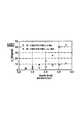
この実験の結果を図2に示す。図2において、横軸はA−スキャン方向の被計測物体の深さ(Depth、単位はmm)を示し、縦軸はスペクトル干渉信号の位相差の標準偏差(σφ)を示し、単位は度(degree)である。そして、○印は第1の補正処理手段を使用した場合の算出値を示し、×印は第1の補正処理手段を使用しない場合の算出値を示している。The result of this experiment is shown in FIG. In FIG. 2, the horizontal axis indicates the depth (Depth, unit: mm) of the measured object in the A-scan direction, the vertical axis indicates the standard deviation (σφ ) of the phase difference of the spectrum interference signal, and the unit is degree. (Degree). A circle indicates a calculated value when the first correction processing means is used, and a cross indicates a calculated value when the first correction processing means is not used.
この実験の結果によると、第1の補正処理手段を使用の有無にかかわらず、A−スキャン方向の被計測物体の深さによって位相差の標準偏差が異なり、より深い領域においては、位相差の標準偏差が大きくなる。 According to the result of this experiment, the standard deviation of the phase difference differs depending on the depth of the object to be measured in the A-scan direction, regardless of whether the first correction processing unit is used or not. The standard deviation increases.
そして、第1の補正処理手段を使用した場合は、使用しない場合より位相差の標準偏差は小さい。従って、第1の補正処理手段を使用すると、A−スキャン方向の被計測物体の深さ方向の全領域にわたって、スペクトル干渉信号の位相差の標準偏差が小さくなり位相の安定性が改善されることが実証された。 When the first correction processing means is used, the standard deviation of the phase difference is smaller than when it is not used. Therefore, when the first correction processing unit is used, the standard deviation of the phase difference of the spectrum interference signal is reduced over the entire region in the depth direction of the measured object in the A-scan direction, and the phase stability is improved. Has been demonstrated.
<第2の補正処理手段>(スペクトルシフトの残差とバルクモーションの補正手段)
ドップラーOCT像である隣接したA−スキャンのスペクトル干渉信号間の位相差は、そのA−スキャンと隣のA−スキャンの複素共役を掛け合わせた信号の位相成分として得られる(前記式(2’)参照)。<Second Correction Processing Unit> (Spectrum Shift Residual and Bulk Motion Correction Unit)
The phase difference between adjacent A-scan spectral interference signals which are Doppler OCT images is obtained as a phase component of a signal obtained by multiplying the complex conjugate of the A-scan and the adjacent A-scan (the above equation (2 ′)). )reference).
参照光と物体光の光路差がゼロ(ゼロディレイ)付近の大きなスペクトルシフトは、第1の補正処理手段で補正可能である。しかし、ゼロディレイから遠い信号はエラー(スペクトルシフトの残差)が残る。また、バルクモーションも補正されていない。 A large spectral shift where the optical path difference between the reference light and the object light is near zero (zero delay) can be corrected by the first correction processing means. However, an error (residual of spectral shift) remains in a signal far from zero delay. Also, bulk motion is not corrected.
そこで、SS−OCT計測のスペクトル干渉信号は、第1の補正処理手段で補正してからさらに、次の式(9)で表される「ドップラー位相シフトΔφ(ζ)」で補正する。
Δφ(ζ)=(4πτ/λC)nvz(ζ)+(4πτ/λC)vb −2πζβ’/N
・・・(9)Therefore, the spectrum interference signal of SS-OCT measurement is corrected by the first correction processing means, and further corrected by “Doppler phase shift Δφ (ζ)” expressed by the following equation (9).
Δφ (ζ) = (4πτ / λC ) nvz (ζ) + (4πτ / λC ) vb −2πζβ ′ / N
... (9)
ここで、τは2つのA−スキャン間の時間、λC は光源の中心波長、nは屈折率、変数ζの関数vz(ζ)は光軸方向の速度、vbはバルクモーションの速度、β’はジッターによるスペクトルシフトの残差、Nはサンプリング点数、ζの関数vz(ζ)は光軸方向の速度、ζは被計測物体の深さを示す変数をそれぞれ示し、ζ=0,1,・・・・N−1である。Here, τ is the time between two A-scans, λC is the center wavelength of the light source, n is the refractive index, the function vz (ζ) of the variable ζ is the velocity in the optical axis direction, and vb is the velocity of the bulk motion. , Β ′ are residuals of spectral shift due to jitter, N is the number of sampling points, ζ function vz (ζ) is the velocity in the optical axis direction, ζ is a variable indicating the depth of the object to be measured, and ζ = 0 , 1,... N−1.
この式において、第1項の(4πτ/λC)nvz(ζ)は、計測したいドップラー信号である。第2項の(4πτ/λC)vbは、バルクモーションに起因する信号であり、深さζに依存しない定数である。In this equation, the first term (4πτ / λC ) nvz (ζ) is a Doppler signal to be measured. The second term (4πτ / λC ) vb is a signal due to the bulk motion and is a constant independent of the depth ζ.
第1項の−2πζβ’/Nにおける「β’」は、前記のとおりジッターによるスペクトルシフトの残差であるが、第1の補正処理手段による補正しない状態のスペクトルシフトβは、第1の補正処理手段で補正すると、その大部分は、第1の補正処理手段による補正で取り除かれる。そして、その残差β’は小さいので、2πの位相のたたみ込みはここでは生じない。 “Β ′” in −2πζβ ′ / N in the first term is the residual of the spectral shift due to jitter as described above, but the spectral shift β in the state not corrected by the first correction processing means is the first correction. When the correction is performed by the processing means, most of the correction is removed by the correction by the first correction processing means. Since the residual β ′ is small, no 2π phase convolution occurs here.
ドップラー信号vz(ζ)がない領域(血液等の動きのない領域)では、第1項は無視できるので、式(9)のΔφ(ζ)は、ζの切片が4πτvb/λCであり、傾きが−2πβ’/Nの1次関数となる。In a region where there is no Doppler signal vz (ζ) (region where there is no movement of blood or the like), the first term can be ignored. Therefore, Δφ (ζ) in Equation (9) is an intercept of 4πτvb / λC. Yes, the slope is a linear function with −2πβ ′ / N.
この切片と傾きは、次の式(10)で表される誤差エネルギーを最小とする傾きamと切片bmを反復法によって求めることで決めることができる。
R22=ΣζWm(ζ)[Δφ(ζ)−(amζ+bm)]2 ・・・(10)
ここで、m=0,1,2…… であり、Wm(ζ)は、反復法で誤差エネルギーを最小化する際の各ζにおける誤差の重要性を表す重み関数である。The intercept and the slope may be determined by determining the slope am and intercept bm that minimizes the error energy is expressed by the following equation (10) by an iterative method.
R22 =Σζ Wm (ζ) [Δφ (ζ) − (am ζ + bm )]2 (10)
Here, m = 0, 1, 2,..., And Wm (ζ) is a weight function that represents the importance of the error in each ζ when the error energy is minimized by the iterative method.
反復法の式(10)において、m=0、即ち初期値W0(ζ)は次の式(11)で示される。
I(ζ)>ε2 の場合:W0(ζ)=(I(ζ))1/2
その他の場合 :W0(ζ)=0
・・・ (11)
ここで、I(ζ)はOCTの強度信号,εはノイズレベルである。In equation (10) of the iterative method, m = 0, that is, the initial value W0 (ζ) is expressed by the following equation (11).
When I (ζ)> ε2 : W0 (ζ) = (I (ζ))1/2
In other cases: W0 (ζ) = 0
(11)
Here, I (ζ) is an OCT intensity signal, and ε is a noise level.
重みの更新は、次の式(12)で行う。
|Δφ(ζ)−(am−1ζ+bm−1)|≧π/2mの場合: Wm(ζ)=0
その他の場合: Wm(ζ)=Wm−1
・・・(12)The weight is updated by the following equation (12).
| Δφ (ζ) − (am−1 ζ + bm−1 ) | ≧ π / 2m : Wm (ζ) = 0
Other cases: Wm (ζ) = Wm−1
(12)
ここで、m=1,2,…である。つまり、誤差エネルギーが所定の閾値、例えば、π/2mより小さい場合は、重みをゼロとする。それ以外の場合は重みは更新されない、ということである。閾値は繰り返し回数mが大きくなると低くなる。mの最大値は(たとえば6などに)予め決めておく。 Here, m = 1, 2,. That is, when the error energy is smaller than a predetermined threshold, for example, π / 2m, the weight is set to zero. Otherwise, the weight is not updated. The threshold value decreases as the number of repetitions m increases. The maximum value of m is predetermined (for example, 6).
以上、本発明に係る波長走査型光干渉断層計及びその位相安定化プログラムを実施するための最良の形態を実施例に基づいて説明したが、本発明はこのような実施例に限定されることなく、特許請求の範囲記載の技術的事項の範囲内で、いろいろな実施例があることは言うまでもない。 The best mode for carrying out the wavelength scanning optical coherence tomography and its phase stabilization program according to the present invention has been described based on the embodiments. However, the present invention is limited to such embodiments. It goes without saying that there are various embodiments within the scope of the technical matters described in the claims.
本発明に係る波長走査型光干渉断層計及びその位相安定化プログラムは、眼底血流の検査に有用であり、これにより、緑内障、糖尿病網膜症の初期検出が可能である。また、腫瘍イメージングにも有用であり、悪性腫瘍における新生血管の三次元可視化が可能である。その他、消化器OCTなどへの応用、及び、動物実験への応用が期待される。 The wavelength scanning optical coherence tomography and its phase stabilization program according to the present invention are useful for examination of fundus blood flow, thereby enabling early detection of glaucoma and diabetic retinopathy. It is also useful for tumor imaging and enables three-dimensional visualization of new blood vessels in malignant tumors. In addition, it is expected to be applied to digestive organ OCT and animal experiments.
1 波長走査型OCT
2 波長走査型光源
3、5、7、14 ファイバー
4 ファイバーカップラー
6 被計測物体
8 固定参照鏡
10 走査鏡
11、12、13 レンズ
15 光検知器
17 ディスプレー1 Wavelength scanning OCT
2 Wavelength scanning light source
3, 5, 7, 14 fiber
4 Fiber coupler
6 Object to be measured
8 Fixed reference mirror
10
Claims (4)
Translated fromJapanese前記補正手段は、隣接する2つのA−スキャンにおいて、基準となる第1のA−スキャンのスペクトル干渉信号S1(j)と、第2のA−スキャンのスペクトル干渉信号であってジッターによるスペクトルシフトβを受けたスペクトル干渉信号S’2(j)とから、下記の式に従い、スペクトルシフトβを求め、このスペクトルシフトβを消去することにより、スペクトル干渉信号の位相データの補正を行うことを特徴とするSS−OCTの位相を安定化するプログラム。
Angle[F[S’2(j)](ζ)F[S1*(j)](ζ)]=−2πζβ/N
但し、jはスペクトルのサンプリング点、即ちA−スキャンにおける深さ方向(光軸方向)の座標であり、Nはサンプリング点数であり、ζは被計測物体の深さを示す変数でζ=0,1,・・・・N−1であり、F[ ]は[ ]内をフーリエ変換した式であり、Angle[]は[]内の位相を表す式であり、* は複素共約を示す。In SS-OCT, the spectral interference detected by the light detector by superimposing the reference light emitted from the wavelength scanning light source, divided and reflected by the fixed reference mirror, and the object light reflected by the object to be measured A program for stabilizing the phase of a spectrum interference signal of SS-OCT that causes a computer that generates a tomographic image based on the signal to function as a correction unit that corrects phase data of the spectrum interference signal,
In the two adjacent A-scans, the correction means includes a spectrum interference signal S1 (j) of the first A-scan serving as a reference, and a spectrum interference signal of the second A-scan and a spectrum caused by jitter. since receiving the shift beta spectral interference signal S'2 and(j),do the following formulato obtain the spectral shift beta, by erasing the spectral shift beta, by correcting the phase data of spectral interference signals The program which stabilizes the phase of SS-OCT characterized by these.
Angle [F [S ′2(j)] (ζ) F [S1*(j)] (ζ)] = − 2πζβ / N
Wherej is a sampling point of the spectrum, that is, coordinates in the depth direction (optical axis direction) in the A-scan, N is the number of sampling points, ζ is a variable indicating the depth of the object to be measured, and ζ = 0, 1,..., N−1, F [] is an expression obtained by Fourier transform in [], Angle [] is an expression representing a phase in [], and* indicates a complex co-agreement.
前記第1の補正手段は、隣接する2つのA−スキャンにおいて、基準となる第1のA−スキャンのスペクトル干渉信号S1(j)と、第2のA−スキャンのスペクトル干渉信号であってジッターによるスペクトルシフトβを受けたスペクトル干渉信号S’2(j)とから、下記の式(1)に従い、スペクトルシフトβを求め、このスペクトルシフトβを消去することにより、スペクトル干渉信号の位相データの補正を行い、
前記第2の補正手段は、前記2つのA−スキャンで得られたスペクトル干渉信号に係るドップラー位相シフトを示す下記の式(2)において、ドップラー信号vz(ζ)がない領域における、ζの切片bm=4πτvb/λC、傾きam=−2πβ’/Nの1次関数について、下記の式(3)に示す誤差エネルギーを最小とする傾きamと切片bmを求めることで、バルクモーション及びジッターによるスペクトルシフトβの残差β’を求めて、スペクトル干渉信号の位相データの補正を行うことを特徴とするSS−OCTの位相を安定化するプログラム。
Angle[F[S’2(j)](ζ)F[S1*(j)](ζ)]=−2πζβ/N ・・・(1)
但し、jはスペクトルのサンプリング点、即ちA−スキャンにおける深さ方向(光軸方向)の座標であり、Nはサンプリング点数であり、ζは被計測物体の深さを示す変数でζ=0,1,・・・・N−1であり、F[ ]は[ ]内をフーリエ変換した式であり、Angle[]は[]内の位相を表す式であり、* は複素共約を示す。
Δφ(ζ)=(4πτ/λC)nvz(ζ)+(4πτ/λC)vb −2πζβ’/N
・・・(2)
但し、τは2つのA−スキャン間の時間、λC は光源の中心波長、nは屈折率、変数ζの関数vz(ζ)は光軸方向の速度、vbはバルクモーションの速度、β’はジッターによるスペクトルシフトの残差、Nはサンプリング点数、ζの関数vz(ζ)は光軸方向の速度、ζは被計測物体の深さを示す変数をそれぞれ示し、ζ=0,1,・・・・N−1である。
R22=ΣζWm(ζ)[Δφ(ζ)−(amζ+bm)]2 ・・・(3)
但し、m=0,1,2…… であり、ζは被計測物体の深さを示す変数であり、Wm(ζ)は重みである。In SS-OCT, the spectral interference detected by the light detector by superimposing the reference light emitted from the wavelength scanning light source, divided and reflected by the fixed reference mirror, and the object light reflected by the object to be measured Program for stabilizing the phase of an SS-OCT spectrum interference signal that causes a computer that generates a tomographic image based on the signal to sequentially function as a first correction unit and a second correction unit that correct phase data of the spectrum interference signal Because
In the two adjacent A-scans, the first correction means includes a first A-scan spectrum interference signal S1 (j) as a reference and a second A-scan spectrum interference signal. since spectral interference signal S'2 and(j) that has received the spectral shift beta by jitter,follow the following equation(1), determine the spectral shift beta, by erasing the spectrum shift beta, the spectral interference signal phase Correct the data,
In the following equation (2) showing the Doppler phase shift related to the spectrum interference signal obtained by the two A-scans, the second correction unit is configured to reduce ζ in a region where there is no Doppler signal vz (ζ). For a linear function with an intercept bm = 4πτvb / λC and an inclination am = −2πβ ′ / N, an inclination am and an intercept bm that minimize the error energy shown in the following equation (3) are obtained, A program for stabilizing the phase of SS-OCT characterized by obtaining a residual β ′ of spectrum shift β by jitter and correcting phase data of a spectrum interference signal.
Angle [F [S ′2(j)] (ζ) F [S1*(j)] (ζ)] = − 2πζβ / N (1)
Wherej is a sampling point of the spectrum, that is, coordinates in the depth direction (optical axis direction) in the A-scan, N is the number of sampling points, ζ is a variable indicating the depth of the object to be measured, and ζ = 0, 1,..., N−1, F [] is an expression obtained by Fourier transform in [], Angle [] is an expression representing a phase in [], and* indicates a complex co-agreement.
Δφ (ζ) = (4πτ / λC ) nvz (ζ) + (4πτ / λC ) vb −2πζβ ′ / N
... (2)
Where τ is the time between two A-scans, λC is the center wavelength of the light source, n is the refractive index, the function vz (ζ) of the variable ζ is the velocity in the optical axis direction, vb is the velocity of the bulk motion, β ′ is the residual of the spectral shift due to jitter, N is the number of sampling points, ζ function vz (ζ) is the velocity in the optical axis direction, ζ is a variable indicating the depth of the object to be measured, and ζ = 0, 1,... N-1.
R22 =Σζ Wm (ζ) [Δφ (ζ) − (am ζ + bm )]2 (3)
However, m = 0, 1, 2,..., Ζ is a variable indicating the depth of the measured object, and Wm (ζ) is a weight.
前記コンピュータは、スペクトル干渉信号の位相データを補正してSS−OCTの位相を安定化する補正手段を備えており、
前記補正手段は、隣接する2つのA−スキャンにおいて、基準となる第1のA−スキャンのスペクトル干渉信号S1(j)と、第2のA−スキャンのスペクトル干渉信号であってジッターによるスペクトルシフトβを受けたスペクトル干渉信号S’2(j)とから、下記の式に従い、スペクトルシフトβを求め、このスペクトルシフトβを消去することにより、スペクトル干渉信号の位相データの補正を行うことを特徴とするSS−OCT。
Angle[F[S’2(j)](ζ)F[S1*(j)](ζ)]=−2πζβ/N
但し、jはスペクトルのサンプリング点、即ちA−スキャンにおける深さ方向(光軸方向)の座標であり、Nはサンプリング点数であり、ζは被計測物体の深さを示す変数でζ=0,1,・・・・N−1であり、F[ ]は[ ]内をフーリエ変換した式であり、Angle[]は[]内の位相を表す式であり、* は複素共約を示す。A wavelength scanning light source, and a photodetector that detects a spectral interference signal in which the reference light emitted from the wavelength scanning light source and divided and reflected by a fixed reference mirror and the object light reflected by the object to be measured are superimposed And a computer for generating a tomographic image based on the spectral interference signal detected by the photodetector,
The computer includes correction means for correcting the phase data of the spectrum interference signal to stabilize the phase of SS-OCT,
In the two adjacent A-scans, the correction means includes a spectrum interference signal S1 (j) of the first A-scan serving as a reference, and a spectrum interference signal of the second A-scan and a spectrum caused by jitter. since receiving the shift beta spectral interference signal S'2 and(j),do the following formulato obtain the spectral shift beta, by erasing the spectral shift beta, by correcting the phase data of spectral interference signals SS-OCT characterized by
Angle [F [S ′2(j)] (ζ) F [S1*(j)] (ζ)] = − 2πζβ / N
Wherej is a sampling point of the spectrum, that is, coordinates in the depth direction (optical axis direction) in the A-scan, N is the number of sampling points, ζ is a variable indicating the depth of the object to be measured, and ζ = 0, 1,..., N−1, F [] is an expression obtained by Fourier transform in [], Angle [] is an expression representing a phase in [], and* indicates a complex co-agreement.
前記コンピュータは、スペクトル干渉信号の位相データを順次補正してSS−OCTの位相を安定化する第1の補正手段と第2の補正手段を備えており、
前記第1の補正手段は、隣接する2つのA−スキャンにおいて、基準となる第1のA−スキャンのスペクトル干渉信号S1(j)と、第2のA−スキャンのスペクトル干渉信号であってジッターによるスペクトルシフトβを受けたスペクトル干渉信号S’2(j)とから、下記の式(1)に従い、スペクトルシフトβを求め、このスペクトルシフトβを消去することにより、スペクトル干渉信号の位相データの補正を行い、
前記第2の補正手段は、前記2つのA−スキャンで得られたスペクトル干渉信号に係るドップラー位相シフトを示す下記の式(2)において、ドップラー信号vz(ζ)がない領域における、ζの切片bm=4πτvb/λC、傾きam=−2πβ’/Nの1次関数について、下記の式(3)に示す誤差エネルギーを最小とする傾きamと切片bmを求めることで、バルクモーション及びジッターによるスペクトルシフトβの残差β’を求めて、スペクトル干渉信号の位相データの補正を行うことを特徴とするSS−OCT。
Angle[F[S’2(j)](ζ)F[S1*(j)](ζ)]=−2πζβ/N ・・・(1)
但し、jはスペクトルのサンプリング点、即ちA−スキャンにおける深さ方向(光軸方向)の座標であり、Nはサンプリング点数であり、ζは被計測物体の深さを示す変数でζ=0,1,・・・・N−1であり、F[ ]は[ ]内をフーリエ変換した式であり、Angle[]は[]内の位相を表す式であり、* は複素共約を示す。
Δφ(ζ)=(4πτ/λC)nvz(ζ)+(4πτ/λC)vb −2πζβ’/N
・・・(2)
但し、τは2つのA−スキャン間の時間、λC は光源の中心波長、nは屈折率、変数ζの関数vz(ζ)は光軸方向の速度、vbはバルクモーションの速度、β’はジッターによるスペクトルシフトの残差、Nはサンプリング点数、ζの関数vz(ζ)は光軸方向の速度、ζは被計測物体の深さを示す変数をそれぞれ示し、ζ=0,1,・・・・N−1である。
R22=ΣζWm(ζ)[Δφ(ζ)−(amζ+bm)]2 ・・・(3)
但し、m=0,1,2…… であり、ζは被計測物体の深さを示す変数であり、Wm(ζ)は重みである。A wavelength scanning light source, and a photodetector that detects a spectral interference signal in which the reference light emitted from the wavelength scanning light source and divided and reflected by a fixed reference mirror and the object light reflected by the object to be measured are superimposed And a computer for generating a tomographic image based on the spectral interference signal detected by the photodetector,
The computer includes first correction means and second correction means for sequentially correcting the phase data of the spectrum interference signal to stabilize the phase of SS-OCT,
In the two adjacent A-scans, the first correction means includes a first A-scan spectrum interference signal S1 (j) as a reference and a second A-scan spectrum interference signal. since spectral interference signal S'2 and(j) that has received the spectral shift beta by jitter,follow the following equation(1), determine the spectral shift beta, by erasing the spectral shift beta, the spectral interference signal phase Correct the data,
In the following equation (2) showing the Doppler phase shift related to the spectrum interference signal obtained by the two A-scans, the second correction unit is configured to reduce ζ in a region where there is no Doppler signal vz (ζ). For a linear function with an intercept bm = 4πτvb / λC and an inclination am = −2πβ ′ / N, an inclination am and an intercept bm that minimize the error energy shown in the following equation (3) are obtained, SS-OCT characterized in that a residual β ′ of spectrum shift β by jitter is obtained and phase data of a spectrum interference signal is corrected.
Angle [F [S ′2(j)] (ζ) F [S1*(j)] (ζ)] = − 2πζβ / N (1)
Wherej is a sampling point of the spectrum, that is, coordinates in the depth direction (optical axis direction) in the A-scan, N is the number of sampling points, ζ is a variable indicating the depth of the object to be measured, and ζ = 0, 1,..., N−1, F [] is an expression obtained by Fourier transform in [], Angle [] is an expression representing a phase in [], and* indicates a complex co-agreement.
Δφ (ζ) = (4πτ / λC ) nvz (ζ) + (4πτ / λC ) vb −2πζβ ′ / N
... (2)
Where τ is the time between two A-scans, λC is the center wavelength of the light source, n is the refractive index, the function vz (ζ) of the variable ζ is the velocity in the optical axis direction, vb is the velocity of the bulk motion, β ′ is the residual of the spectral shift due to jitter, N is the number of sampling points, ζ function vz (ζ) is the velocity in the optical axis direction, ζ is a variable indicating the depth of the object to be measured, and ζ = 0, 1,... N-1.
R22 =Σζ Wm (ζ) [Δφ (ζ) − (am ζ + bm )]2 (3)
However, m = 0, 1, 2,..., Ζ is a variable indicating the depth of the measured object, and Wm (ζ) is a weight.
Priority Applications (5)
| Application Number | Priority Date | Filing Date | Title |
|---|---|---|---|
| JP2012000313AJP5900950B2 (en) | 2012-01-05 | 2012-01-05 | Wavelength scanning optical coherence tomography and its phase stabilization program |
| EP12864429.1AEP2801814B1 (en) | 2012-01-05 | 2012-12-14 | Swept source optical coherence tomograph and method for stabilizing phase thereof |
| PCT/JP2012/082460WO2013103080A1 (en) | 2012-01-05 | 2012-12-14 | Swept source optical coherence tomograph and method for stabilizing phase thereof |
| CN201280062822.1ACN104053980B (en) | 2012-01-05 | 2012-12-14 | Wavelength scanning optical coherence tomography and its phase stabilization method |
| US14/368,456US9354038B2 (en) | 2012-01-05 | 2012-12-14 | Swept source optical coherence tomography and method for stabilizing phase thereof |
Applications Claiming Priority (1)
| Application Number | Priority Date | Filing Date | Title |
|---|---|---|---|
| JP2012000313AJP5900950B2 (en) | 2012-01-05 | 2012-01-05 | Wavelength scanning optical coherence tomography and its phase stabilization program |
Publications (2)
| Publication Number | Publication Date |
|---|---|
| JP2013140077A JP2013140077A (en) | 2013-07-18 |
| JP5900950B2true JP5900950B2 (en) | 2016-04-06 |
Family
ID=48745143
Family Applications (1)
| Application Number | Title | Priority Date | Filing Date |
|---|---|---|---|
| JP2012000313AActiveJP5900950B2 (en) | 2012-01-05 | 2012-01-05 | Wavelength scanning optical coherence tomography and its phase stabilization program |
Country Status (5)
| Country | Link |
|---|---|
| US (1) | US9354038B2 (en) |
| EP (1) | EP2801814B1 (en) |
| JP (1) | JP5900950B2 (en) |
| CN (1) | CN104053980B (en) |
| WO (1) | WO2013103080A1 (en) |
Families Citing this family (31)
| Publication number | Priority date | Publication date | Assignee | Title |
|---|---|---|---|---|
| US9207062B2 (en)* | 2012-12-10 | 2015-12-08 | The Johns Hopkins University | Distortion corrected optical coherence tomography system |
| JP6180877B2 (en)* | 2013-10-02 | 2017-08-16 | 株式会社トプコン | Optical image measuring device |
| EP3111833B1 (en)* | 2014-01-31 | 2024-11-27 | The General Hospital Corporation | Method and apparatus for performing multidimensional velocity measurements based on amplitude and phase signals in the field of optical interferometry |
| US9763570B2 (en)* | 2014-02-04 | 2017-09-19 | University Of Southern California | Optical coherence tomography (OCT) system with phase-sensitive B-scan registration |
| CN104168823B (en)* | 2014-02-28 | 2017-01-18 | 深圳市斯尔顿科技有限公司 | Device and method for measuring blood flow velocity |
| JP6798095B2 (en)* | 2014-12-02 | 2020-12-09 | 株式会社ニデック | Optical coherence tomography equipment and control programs used for it |
| WO2016099923A1 (en) | 2014-12-17 | 2016-06-23 | Pgs Geophysical As | Optical filter |
| MX384940B (en)* | 2014-12-17 | 2025-03-14 | Geospace Tech Corporation | PRESSURE-INSENSITIVE INTERFEROMETER. |
| CN104622474B (en)* | 2015-03-09 | 2016-11-23 | 莆田市荔城区聚慧科技咨询有限公司 | A kind of Measurement of surface deepth device |
| CN104849221B (en)* | 2015-05-21 | 2017-04-26 | 清华大学深圳研究生院 | Optical coherence tomography-based phase calibration method |
| US10129131B2 (en)* | 2015-06-30 | 2018-11-13 | Dell Products, Lp | System and method for device optimization in a network of devices with embedded electronics |
| KR101640348B1 (en)* | 2015-08-17 | 2016-07-18 | 세종대학교산학협력단 | Apparatus of high precision optical scanning |
| CN105342558B (en)* | 2015-09-30 | 2017-11-14 | 苏州大学 | Correction method based on phase error in optical coherence tomography imaging |
| JP7019700B2 (en) | 2016-12-21 | 2022-02-15 | アキュセラ インコーポレイテッド | Optical coherence tomography (OCT) system for measuring retina thickness |
| US20180360655A1 (en)* | 2017-06-16 | 2018-12-20 | Michael S. Berlin | Methods and systems for oct guided glaucoma surgery |
| JP2017185342A (en)* | 2017-07-18 | 2017-10-12 | 株式会社トプコン | Optical image measuring device |
| JP7144822B2 (en)* | 2017-12-22 | 2022-09-30 | 株式会社トーメーコーポレーション | Optical tomography system |
| CN112203579A (en)* | 2018-04-02 | 2021-01-08 | 俄勒冈健康与科学大学 | System and method for volume motion compensation in phase-based functional optical coherence tomography |
| CN112638233B (en) | 2018-06-20 | 2024-06-14 | 奥克塞拉有限公司 | Miniature mobile low cost optical coherence tomography system for home-based ophthalmic applications |
| CN108956533A (en)* | 2018-07-13 | 2018-12-07 | 福州大学 | A kind of OCT conjugation mirror image removal device and method for eliminating polychrome error |
| JP7587847B2 (en)* | 2019-11-14 | 2024-11-21 | 国立大学法人 筑波大学 | Signal processing device, signal processing method, and signal processing program |
| EP4081096A4 (en) | 2019-12-26 | 2024-01-10 | Acucela Inc. | Optical coherence tomography patient alignment system for home based ophthalmic applications |
| JP7411913B2 (en)* | 2020-06-03 | 2024-01-12 | パナソニックIpマネジメント株式会社 | OCT measurement device and OCT measurement method |
| US10959613B1 (en) | 2020-08-04 | 2021-03-30 | Acucela Inc. | Scan pattern and signal processing for optical coherence tomography |
| JP2023538542A (en) | 2020-08-14 | 2023-09-08 | アキュセラ インコーポレイテッド | Systems and methods for optical coherence tomography A-scan decarving |
| CN111829954B (en)* | 2020-09-09 | 2023-07-25 | 广东工业大学 | System and method for improving full-field sweep-frequency optical coherence tomography measurement range |
| US11393094B2 (en) | 2020-09-11 | 2022-07-19 | Acucela Inc. | Artificial intelligence for evaluation of optical coherence tomography images |
| JP2023544704A (en) | 2020-09-30 | 2023-10-25 | アキュセラ インコーポレイテッド | Myopia prediction, diagnosis, planning, and monitoring devices |
| US11974806B2 (en)* | 2021-02-19 | 2024-05-07 | Topcon Corporation | Ophthalmologic information processing apparatus, ophthalmologic apparatus, ophthalmologic information processing method, and recording medium |
| US11497396B2 (en) | 2021-03-24 | 2022-11-15 | Acucela Inc. | Axial length measurement monitor |
| CN115388796B (en)* | 2022-06-27 | 2025-05-23 | 重庆大学 | A dynamic gap measurement method based on fast sparse frequency scanning interferometry |
Family Cites Families (14)
| Publication number | Priority date | Publication date | Assignee | Title |
|---|---|---|---|---|
| US5501226A (en)* | 1994-10-19 | 1996-03-26 | Carl Zeiss, Inc. | Short coherence length, doppler velocimetry system |
| DE19814057B4 (en) | 1998-03-30 | 2009-01-02 | Carl Zeiss Meditec Ag | Arrangement for optical coherence tomography and coherence topography |
| JP2002310897A (en) | 2001-04-13 | 2002-10-23 | Japan Science & Technology Corp | High-speed optical delay generation method by movement of light-transmitting body in optical coherence tomography and high-speed optical delay generation device |
| JP4045140B2 (en) | 2002-06-21 | 2008-02-13 | 国立大学法人 筑波大学 | Polarization-sensitive optical spectral interference coherence tomography apparatus and method for measuring polarization information inside a sample using the apparatus |
| EP2280256B1 (en)* | 2003-10-27 | 2016-11-16 | The General Hospital Corporation | Method and apparatus for performing optical imaging using frequency-domain interferometry |
| CA2603495A1 (en)* | 2005-04-01 | 2006-10-12 | Visualsonics Inc. | System and method for 3-d visualization of vascular structures using ultrasound |
| US9060689B2 (en) | 2005-06-01 | 2015-06-23 | The General Hospital Corporation | Apparatus, method and system for performing phase-resolved optical frequency domain imaging |
| CN100512752C (en)* | 2007-01-12 | 2009-07-15 | 天津市先石光学技术有限公司 | Optical distance optional type atraumatic human body component measuring method and apparatus therefor |
| JP4389032B2 (en)* | 2007-01-18 | 2009-12-24 | 国立大学法人 筑波大学 | Optical coherence tomography image processing device |
| JP5683946B2 (en)* | 2007-04-10 | 2015-03-11 | ユニヴァーシティー オブ サザン カリフォルニア | Method and system for blood flow measurement using Doppler optical coherence tomography |
| JP2010014514A (en)* | 2008-07-03 | 2010-01-21 | Fujifilm Corp | Optical tomographic imaging apparatus and coherent signal processing method in optical tomographic imaging apparatus |
| US8133127B1 (en)* | 2008-07-21 | 2012-03-13 | Synder Terrance W | Sports training device and methods of use |
| JP5725697B2 (en)* | 2009-05-11 | 2015-05-27 | キヤノン株式会社 | Information processing apparatus and information processing method |
| US9192294B2 (en)* | 2012-05-10 | 2015-11-24 | Carl Zeiss Meditec, Inc. | Systems and methods for faster optical coherence tomography acquisition and processing |
- 2012
- 2012-01-05JPJP2012000313Apatent/JP5900950B2/enactiveActive
- 2012-12-14WOPCT/JP2012/082460patent/WO2013103080A1/enactiveApplication Filing
- 2012-12-14CNCN201280062822.1Apatent/CN104053980B/ennot_activeExpired - Fee Related
- 2012-12-14EPEP12864429.1Apatent/EP2801814B1/ennot_activeNot-in-force
- 2012-12-14USUS14/368,456patent/US9354038B2/enactiveActive
Also Published As
| Publication number | Publication date |
|---|---|
| EP2801814B1 (en) | 2018-04-18 |
| EP2801814A1 (en) | 2014-11-12 |
| US9354038B2 (en) | 2016-05-31 |
| EP2801814A4 (en) | 2015-09-02 |
| US20150009507A1 (en) | 2015-01-08 |
| WO2013103080A1 (en) | 2013-07-11 |
| CN104053980A (en) | 2014-09-17 |
| CN104053980B (en) | 2016-05-18 |
| JP2013140077A (en) | 2013-07-18 |
Similar Documents
| Publication | Publication Date | Title |
|---|---|---|
| JP5900950B2 (en) | Wavelength scanning optical coherence tomography and its phase stabilization program | |
| US7602501B2 (en) | Interferometric synthetic aperture microscopy | |
| JP5787255B2 (en) | Program for correcting measurement data of PS-OCT and PS-OCT system equipped with the program | |
| US9706915B2 (en) | Method of motion correction in optical coherence tomography imaging | |
| JP6346410B2 (en) | Jones Matrix OCT System and Program for Image Processing of Measurement Data Obtained by OCT | |
| JP5626687B2 (en) | 2-beam optical coherence tomography system | |
| CN102970919B (en) | Optical coherence tomography and method thereof | |
| JP4461259B2 (en) | Optical tomographic image processing method | |
| KR101704113B1 (en) | Method and apparatus for processing polarization data of polarization sensitive optical coherence tomography | |
| JP5864258B2 (en) | Method and apparatus for collecting structural data using spectral optical coherence tomography | |
| JP6491540B2 (en) | Optical coherence tomography and control method thereof | |
| WO2012107307A1 (en) | Optimized device for swept source optical coherence domain reflectometry and tomography | |
| JP2016209182A (en) | Imaging apparatus, operating method of imaging apparatus, information processing apparatus, and operating method of information processing apparatus | |
| JP2007127425A (en) | Correction method in optical tomography | |
| JP6606640B2 (en) | Ophthalmic apparatus and control method thereof | |
| JP6579718B2 (en) | Jones Matrix OCT Device and Program | |
| JP6779662B2 (en) | Imaging device, control method of imaging device, and program | |
| US20230358527A1 (en) | Optical interference tomographic imaging device | |
| WO2021192047A1 (en) | Optical coherence tomography device, imaging method, and non-transitory computer-readable medium in which imaging program is stored |
Legal Events
| Date | Code | Title | Description |
|---|---|---|---|
| A621 | Written request for application examination | Free format text:JAPANESE INTERMEDIATE CODE: A621 Effective date:20141222 | |
| A131 | Notification of reasons for refusal | Free format text:JAPANESE INTERMEDIATE CODE: A131 Effective date:20151208 | |
| A521 | Request for written amendment filed | Free format text:JAPANESE INTERMEDIATE CODE: A523 Effective date:20160126 | |
| TRDD | Decision of grant or rejection written | ||
| A01 | Written decision to grant a patent or to grant a registration (utility model) | Free format text:JAPANESE INTERMEDIATE CODE: A01 Effective date:20160223 | |
| A61 | First payment of annual fees (during grant procedure) | Free format text:JAPANESE INTERMEDIATE CODE: A61 Effective date:20160303 | |
| R150 | Certificate of patent or registration of utility model | Ref document number:5900950 Country of ref document:JP Free format text:JAPANESE INTERMEDIATE CODE: R150 | |
| R250 | Receipt of annual fees | Free format text:JAPANESE INTERMEDIATE CODE: R250 | |
| R250 | Receipt of annual fees | Free format text:JAPANESE INTERMEDIATE CODE: R250 | |
| R250 | Receipt of annual fees | Free format text:JAPANESE INTERMEDIATE CODE: R250 | |
| R250 | Receipt of annual fees | Free format text:JAPANESE INTERMEDIATE CODE: R250 | |
| R250 | Receipt of annual fees | Free format text:JAPANESE INTERMEDIATE CODE: R250 | |
| R250 | Receipt of annual fees | Free format text:JAPANESE INTERMEDIATE CODE: R250 | |
| R250 | Receipt of annual fees | Free format text:JAPANESE INTERMEDIATE CODE: R250 |