JP5891105B2 - Field device adapter and field device - Google Patents
Field device adapter and field deviceDownload PDFInfo
- Publication number
- JP5891105B2 JP5891105B2JP2012106571AJP2012106571AJP5891105B2JP 5891105 B2JP5891105 B2JP 5891105B2JP 2012106571 AJP2012106571 AJP 2012106571AJP 2012106571 AJP2012106571 AJP 2012106571AJP 5891105 B2JP5891105 B2JP 5891105B2
- Authority
- JP
- Japan
- Prior art keywords
- field device
- position information
- attached
- physical quantity
- adapter
- Prior art date
- Legal status (The legal status is an assumption and is not a legal conclusion. Google has not performed a legal analysis and makes no representation as to the accuracy of the status listed.)
- Expired - Fee Related
Links
Images


Landscapes
- Measuring Fluid Pressure (AREA)
- Arrangements For Transmission Of Measured Signals (AREA)
Description
Translated fromJapaneseこの発明は、圧力発信器などのフィールド機器用のアダプタおよびフィールド機器に関するものである。 The present invention relates to an adapter for a field device such as a pressure transmitter and a field device.
従来より、4〜20mAの有線計装では、物理量を計測する圧力発信器などのフィールド機器と、このフィールド機器から送られてくる物理量の計測値を受信する上位装置とは、物理的に1対1に接続が決まっているため、どの上位装置のスロットがどの場所の物理量を計測しているのかは明確である。 Conventionally, in wired instrumentation of 4 to 20 mA, a field device such as a pressure transmitter that measures a physical quantity and a host device that receives a measurement value of a physical quantity sent from the field equipment are physically paired. Since the connection is determined as 1, it is clear which slot of the higher-level device measures the physical quantity at which location.
これに対し、無線計装では、フィールド機器から送られてくる物理量の計測値がどの場所の物理量を計測しているのかを特定することは難しい。このため、例えば、特許文献1に示されたフィールド機器探索システムでは、フィールド機器からの電波を受信し、その電波が伝わってきた経路からそのフィールド機器の位置を推定するようにしている。 On the other hand, in wireless instrumentation, it is difficult to specify which physical quantity is measured by a physical quantity measurement value sent from a field device. For this reason, for example, in the field device search system disclosed in
しかしながら、特許文献1に示されたフィールド機器探索システムでは、電波が伝わってきた経路からフィールド機器のおおよその位置は分かるが、近接する配管のどこに取り付いているかまでを判別することはできない。 However, in the field device search system disclosed in
なお、上述した例は無線計装の場合を示したが、フィールドバスのようなマルチドロップ配線の場合も、フィールドバスに接続された1つのセグメント内は同一に見えるため、セグメント内のフィールド機器の位置を細かく特定することができず、同様の問題を含んでいる。 The above-described example shows the case of wireless instrumentation. However, in the case of multi-drop wiring such as a field bus, one segment connected to the field bus looks the same. The position cannot be specified in detail, and the same problem is included.
本発明は、このような課題を解決するためになされたもので、その目的とするところは、フィールド機器が取り付けられている位置を正確に知ることが可能なフィールド機器用アダプタおよびフィールド機器を提供することにある。 The present invention has been made to solve such problems, and an object of the present invention is to provide a field device adapter and a field device capable of accurately knowing a position where the field device is attached. There is to do.
このような目的を達成するために本発明は、物理量の計測点に取り付けられ、この物理量の計測点に取り付けられている状態において、任意のフィールド機器が着脱可能に取り付けられるフィールド機器用アダプタであって、物理量の計測点の位置情報がセットされる位置情報セット手段と、任意のフィールド機器が取り付けられた場合、この取り付けられたフィールド機器からのセットされている位置情報の読み取りを可能とする位置情報出力手段とを備えることを特徴とする。 In order to achieve such an object, the present invention is a field device adapter that is attached to a physical quantity measurement point and to which any field device can be detachably attached in the state of being attached to the physical quantity measurement point. The position information setting means for setting the position information of the measurement point of the physical quantity and the position where the set position information can be read from the attached field device when an arbitrary field device is attached. And an information output means.
本発明のフィールド機器用アダプタは、位置情報セット手段と位置情報出力手段とを備えているが、位置情報セット手段の一例として、位置情報がオン/オフの組み合わせでセットされる複数の接点とすることが考えられる。また、位置情報出力手段の一例として、複数の接点と取り付けられたフィールド機器とを結ぶ導通路とすることが考えられる。 The field device adapter of the present invention includes the position information setting means and the position information output means. As an example of the position information setting means, a plurality of contact points where the position information is set in an on / off combination are used. It is possible. Further, as an example of the position information output means, it is conceivable to use a conduction path that connects a plurality of contacts and attached field devices.
本発明のフィールド機器用アダプタは、物理量の計測点に取り付けられ、位置情報セット手段にはその取り付けられた物理量の計測点の位置情報がセットされる。フィールド機器用アダプタにフィールド機器を取り付けると、フィールド機器用アダプタにセットされている位置情報が、そのフィールド機器の物理量の計測点の位置情報として読み取られる。 The field device adapter of the present invention is attached to a physical quantity measurement point, and position information of the attached physical quantity measurement point is set in the position information setting means. When the field device is attached to the field device adapter, the position information set in the field device adapter is read as the position information of the physical quantity measurement point of the field device.
本発明のフィールド機器用アダプタに取り付けられるフィールド機器は、取り付けられたフィールド機器用アダプタにセットされている位置情報を読み取る位置情報読取手段と、取り付けられたフィールド機器用アダプタが取り付けられている計測点の物理量を計測する物理量計測手段と、読み取った位置情報および計測した物理量を上位装置に送信する送信手段とを備えるものとする。これにより、フィールド機器から上位装置に、物理量の計測点の位置情報と計測された物理量が送られ、上位装置においてフィールド機器がどこに取り付けられているかを正確に知ることが可能となる。 The field device attached to the field device adapter of the present invention includes position information reading means for reading position information set in the attached field device adapter, and a measurement point to which the attached field device adapter is attached. It is assumed that a physical quantity measuring means for measuring the physical quantity and a transmitting means for sending the read position information and the measured physical quantity to the host device. As a result, the positional information of the measurement point of the physical quantity and the measured physical quantity are sent from the field device to the host device, and it is possible to accurately know where the field device is attached in the host device.
本発明によれば、任意のフィールド機器が着脱可能に取り付けられるフィールド機器用アダプタに、物理量の計測点の位置情報がセットされる位置情報セット手段と、任意のフィールド機器が取り付けられた場合、この取り付けられたフィールド機器からのセットされている位置情報の読み取りを可能とする位置情報出力手段とを設けたので、フィールド機器用アダプタにフィールド機器を取り付けると、フィールド機器用アダプタにセットされている位置情報がそのフィールド機器の物理量の計測点の位置情報として読み取られるものとなり、この読み取られた位置情報からフィールド機器が取り付けられている位置を正確に知ることが可能となる。 According to the present invention, when an arbitrary field device is attached to the field device adapter to which an arbitrary field device is detachably attached, the position information setting means for setting the position information of the measurement point of the physical quantity and the arbitrary field device are attached. Since the position information output means for enabling reading of the set position information from the attached field device is provided, when the field device is attached to the field device adapter, the position set in the field device adapter The information is read as the position information of the physical quantity measurement point of the field device, and the position where the field device is attached can be accurately known from the read position information.
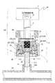
以下、本発明の実施の形態を図面に基づいて詳細に説明する。図1はこの発明に係るフィールド機器用アダプタの一実施の形態を示す断面図である。 Hereinafter, embodiments of the present invention will be described in detail with reference to the drawings. FIG. 1 is a sectional view showing an embodiment of a field device adapter according to the present invention.
このフィールド機器用アダプタ(以下、配管側ジョイントと呼ぶ)1は、円盤上の台座部1−1と、この台座部1−1の中央部より下面側に伸びるパイプ部1−2とを備えている。台座部1−1およびパイプ部1−1は金属製とされており、台座部1−1の外周部1aおよびパイプ部1−2の下端部1bにはネジ部が形成されている。また、台座部1−1の下面1cには、パイプ部1−2の周囲にリング状の溝1dが形成されており、このリング状の溝1dの底面に接点基板1−3が固定されている。 This field device adapter (hereinafter referred to as a pipe-side joint) 1 includes a pedestal part 1-1 on a disk and a pipe part 1-2 extending from the central part of the pedestal part 1-1 to the lower surface side. Yes. The pedestal part 1-1 and the pipe part 1-1 are made of metal, and screw parts are formed on the outer
接点基板1−3には、図2に示すように、接点S1〜S4が形成されており、接点S1〜S4の一端は台座部1−1をGNDとして共通に接続されている。接点S1〜S4の他端は、リードピンLP1〜LP4に接続されている。このリードピンLP1〜LP4は、接点基板1−3の回路上に半田接続され、台座部1−1に形成された貫通孔1e1〜1e4を通して、台座部1−1の上面1fよりもさらに上方に突出している。台座部1−1の上面1fには後述するセンサ側ジョイント4(図4)との組み合わせに際する位置決め用のスタッド1gが複数設けられている。また、台座部1−1の上面1fの中央部にはパイプ部1−2の開口が臨む段差孔1hが形成されている。 As shown in FIG. 2, contacts S <b> 1 to S <b> 4 are formed on the contact board 1-3, and one end of each of the contacts S <b> 1 to S <b> 4 is connected in common with the pedestal portion 1-1 being GND. The other ends of the contacts S1 to S4 are connected to the lead pins LP1 to LP4. The lead pins LP1 to LP4 are soldered on the circuit of the contact board 1-3, and protrude further upward than the
図3にこの配管側ジョイント1を配管100に取り付けた状態を示す。配管100には、圧力の計測点として定められた各箇所に、配管側ジョイント1の取付部100aが設けられている。この配管側ジョイント1の取付部100aに、配管側ジョイント1のパイプ部1−2の下端部1bに形成されたネジ部を螺合して、配管側ジョイント1を取り付ける。この際、接点基板1−3に形成されている接点S1〜S4のオン/オフの組み合わせで、配管側ジョイント1を取り付けた圧力の計測点の位置情報をセットする。この例では、接点基板1−3に4つの接点S1〜S4を形成しているので、最大16ポイントの位置情報をセットすることが可能である。 FIG. 3 shows a state where the
この配管100に取り付けられた配管側ジョイント1に図4に示すように任意の圧力発信器200を取り付ける。圧力発信器200は、CPU21を内蔵する圧力発信器本体2と、この圧力発信器本体2にフレキシブルケーブル3を介して電気的に接続されたセンサ側ジョイント4とから構成されている。センサ側ジョイント4は、センサボディ41と、このセンサボディ41の外周に遊嵌されたユニオンナット42と、センサボディ41に溶接されてユニオンナット42の脱落を防ぐストッパ43とから構成されている。センサボディ41,ユニオンナット42およびストッパ43は金属製とされている。 As shown in FIG. 4, an
センサボディ41には、圧力センサ44が設けられており、この圧力センサ44のセンサダイアフラム(図示せず)と受圧ダイアフラム45との間に圧力伝達媒体として封入液46が封入されている。圧力センサ44のセンサダイアフラム上には歪み抵抗ゲージが形成されており、この歪抵抗ゲージの抵抗値変化に応じた信号が圧力センサ44から出力される。この圧力センサ44から出力される信号は、中継基板47に接続されたフレキシブルケーブル3を介して、圧力発信器本体2に送られる。また、センサボディ41には、ソケットコンタクトSC1〜SC4が埋設されており、ソケットコンタクトSC1〜SC4の端部は中継基板47の回路上に半田接続されている。ソケットコンタクトSC1〜SC4とセンサボディ41との間は絶縁が図られている。 The
このセンサボディ41をユニオンナット42によって配管側ジョイント1に組み付ける。すなわち、リードピンLP1〜LP4をソケットコンタクトSC1〜SC4に挿入し、位置決め用のスタッド1gによって位置合わせを行わせながら、センサボディ41と配管側ジョイント1とを組み合わせ、ユニオンナット42を配管側ジョイント1の台座部1−1の外周部1aに螺合することによって、センサボディ41を配管側ジョイント1に組み付ける。この際、受圧ダイアフラム45の周囲には、パイプ部1−2を介する配管100からの流体が漏れ出ないようにOリング48を介在させる。 The
図5に配管側ジョイント1に圧力発信器200を取り付けた状態における電気回路の概略を示す。この例では、配管側ジョイント1の台座部1−1およびパイプ部1−2を金属性として、センサ側ジョイント4のセンサボディ41,ユニオンナット42およびストッパ43を金属性として、電気的にGND接続を兼ねさせている。 FIG. 5 shows an outline of an electric circuit in a state where the
この配管側ジョイント1と圧力発信器200との取り付け状態において、圧力発信器本体2のCPU21は、配管側ジョイント1の接点基板1−3に形成されている接点S1〜S4のオン/オフの組み合わせを、リードピンLP1〜LP4、ソケットコンタクトSC1〜SC4、フレキシブルケーブル3の経路(導通路)で読み取る。すなわち、配管側ジョイント1にセットされている位置情報を、圧力発信器200の圧力の計測点の位置情報として読み取る。 In the attachment state of the pipe-
また、圧力発信器本体2のCPU21は、圧力センサ44から出力される信号をフレキシブルケーブル3を介して取り込み、配管側ジョイント1が取り付けられている計測点の圧力値を求める。 Further, the
そして、圧力発信器本体2のCPU21は、この読み取った計測点の位置情報および計測された圧力値を上位装置(図示せず)に送信する。この場合、無線で上位装置へ送信するようにしてもよいし、フィールドバスを介して上位装置に送信するようにしてもよい。 Then, the
上位装置には、配管側ジョイント1の配管100への取り付け時に、その取り付けた位置と接点基板1−3に形成されている接点S1〜S4のオン/オフの組み合わせで設定した位置情報との関係が設定されている。これにより、上位装置は、圧力発信器200から送られてくる位置情報に基づき、その圧力発信器200が取り付けられている位置を正確に知ることができる。 In the host device, when the pipe-
本実施の形態では、配管側ジョイント1に計測点の位置情報がセットされているので、圧力発信器200に計測点の位置情報を一々セットする必要がない。例えば、圧力発信器200を交換したいような場合、新しい圧力発信器200に計測点の位置情報をセットしなくても、その圧力発信器200を配管側ジョイント1に取り付ければ、配管側ジョイント1から計測点の位置情報が読み出されて上位装置に通知されるものとなる。これにより、圧力発信器200の交換作業が簡単となる。 In the present embodiment, since the position information of the measurement point is set in the pipe side joint 1, it is not necessary to set the position information of the measurement point in the
なお、上述した実施の形態では、接点基板1−3に形成されている接点の数を4つとしたが、その数は4つに限られるものではことは言うまでもない。また、必ずしも接点のオン/オフの組み合わせで位置情報をセットしなくてもよく、シリアル通信をするメモリを埋め込めばタグ情報で認識させることも可能である。また、接触する接点信号を例にとって説明したが、非接触タグでもよい。 In the above-described embodiment, the number of contacts formed on the contact board 1-3 is four, but it is needless to say that the number is not limited to four. Further, it is not always necessary to set position information by a combination of contact ON / OFF, and it is possible to recognize the tag information by embedding a memory for serial communication. Moreover, although the contact signal which contacts is demonstrated as an example, a non-contact tag may be sufficient.
また、上述した実施の形態では、フィールド機器として圧力発信器を例にとって説明したが、温度計、流量計などのフィールド機器であってもよい。温度計の場合、温度が本発明いう物理量となり、流量計の場合、流量が本発明でいう物理量となる。
〔実施の形態の拡張〕
以上、実施の形態を参照して本発明を説明したが、本発明は上記の実施の形態に限定されるものではない。本発明の構成や詳細には、本発明の技術思想の範囲内で当業者が理解し得る様々な変更をすることができる。In the above-described embodiment, the pressure transmitter is described as an example of the field device. However, a field device such as a thermometer or a flow meter may be used. In the case of a thermometer, the temperature is the physical quantity referred to in the present invention, and in the case of a flow meter, the flow rate is the physical quantity referred to in the present invention.
[Extension of the embodiment]
The present invention has been described above with reference to the embodiment. However, the present invention is not limited to the above embodiment. Various changes that can be understood by those skilled in the art can be made to the configuration and details of the present invention within the scope of the technical idea of the present invention.
1…フィールド機器用アダプタ(配管側ジョイント)、1−1…台座部、1−2…パイプ部、1−3…接点基板、2…圧力発信器本体、3…フレキシブルケーブル、4…センサ側ジョイント、21…CPU、41…センサボディ、42…ユニオンナット、43…ストッパ、44…圧力センサ、45…受圧ダイアフラム、46…封入液、47…中継基板、S1〜S4…接点、LP1〜LP4…リードピン、SC1〜SC4…ソケットコンタクト、100…配管、200…圧力発信器。 DESCRIPTION OF
Claims (3)
Translated fromJapanese前記物理量の計測点の位置情報がセットされる位置情報セット手段と、
前記任意のフィールド機器が取り付けられた場合、この取り付けられたフィールド機器からの前記セットされている位置情報の読み取りを可能とする位置情報出力手段と
を備えることを特徴とするフィールド機器用アダプタ。It is a field device adapter that is attached to a physical quantity measurement point, and in a state where it is attached to the physical quantity measurement point, any field device can be detachably attached,
Position information setting means in which position information of the measurement point of the physical quantity is set;
A field device adapter comprising: a position information output unit that enables reading of the set position information from the attached field device when the arbitrary field device is mounted.
前記位置情報セット手段は、
前記位置情報がオン/オフの組み合わせでセットされる複数の接点であり、
前記位置情報出力手段は、
前記複数の接点と前記取り付けられたフィールド機器とを結ぶ導通路である
ことを特徴とするフィールド機器用アダプタ。In the field device adapter according to claim 1,
The position information setting means includes
A plurality of contact points where the position information is set in a combination of on / off;
The position information output means includes
An adapter for a field device, wherein the field device adapter is a conduction path connecting the plurality of contacts and the attached field device.
取り付けられたフィールド機器用アダプタにセットされている位置情報を読み取る位置情報読取手段と、
取り付けられたフィールド機器用アダプタが取り付けられている計測点の物理量を計測する物理量計測手段と、
前記読み取った位置情報および前記計測した物理量を上位装置に送信する送信手段と
を備えることを特徴とするフィールド機器。A field device detachably attached to the field device adapter according to claim 1 or 2,
Position information reading means for reading position information set in the attached field device adapter;
A physical quantity measuring means for measuring a physical quantity at a measuring point to which the attached field device adapter is attached;
A field device comprising: transmission means for transmitting the read position information and the measured physical quantity to a host device.
Priority Applications (1)
| Application Number | Priority Date | Filing Date | Title |
|---|---|---|---|
| JP2012106571AJP5891105B2 (en) | 2012-05-08 | 2012-05-08 | Field device adapter and field device |
Applications Claiming Priority (1)
| Application Number | Priority Date | Filing Date | Title |
|---|---|---|---|
| JP2012106571AJP5891105B2 (en) | 2012-05-08 | 2012-05-08 | Field device adapter and field device |
Publications (2)
| Publication Number | Publication Date |
|---|---|
| JP2013235361A JP2013235361A (en) | 2013-11-21 |
| JP5891105B2true JP5891105B2 (en) | 2016-03-22 |
Family
ID=49761449
Family Applications (1)
| Application Number | Title | Priority Date | Filing Date |
|---|---|---|---|
| JP2012106571AExpired - Fee RelatedJP5891105B2 (en) | 2012-05-08 | 2012-05-08 | Field device adapter and field device |
Country Status (1)
| Country | Link |
|---|---|
| JP (1) | JP5891105B2 (en) |
Families Citing this family (2)
| Publication number | Priority date | Publication date | Assignee | Title |
|---|---|---|---|---|
| JP6656125B2 (en) | 2016-09-09 | 2020-03-04 | 株式会社鷺宮製作所 | Pressure sensor, its relay board, and its relay board unit |
| CN110595664A (en)* | 2019-08-19 | 2019-12-20 | 江苏杰克仪表有限公司 | Novel high-precision pressure transmitter |
Family Cites Families (5)
| Publication number | Priority date | Publication date | Assignee | Title |
|---|---|---|---|---|
| JP3641163B2 (en)* | 1999-05-19 | 2005-04-20 | 株式会社東芝 | Distributed monitoring and control system |
| JP2007131244A (en)* | 2005-11-11 | 2007-05-31 | Calsonic Kansei Corp | Tire air pressure monitoring device |
| US7692539B2 (en)* | 2006-12-28 | 2010-04-06 | Rosemount Inc. | Automated mechanical integrity verification |
| JP2008171285A (en)* | 2007-01-12 | 2008-07-24 | Ono Sokki Co Ltd | Sensor system and method for measuring with the sensor system |
| JP2009139328A (en)* | 2007-12-10 | 2009-06-25 | Yokogawa Electric Corp | Field device search system |
- 2012
- 2012-05-08JPJP2012106571Apatent/JP5891105B2/ennot_activeExpired - Fee Related
Also Published As
| Publication number | Publication date |
|---|---|
| JP2013235361A (en) | 2013-11-21 |
Similar Documents
| Publication | Publication Date | Title |
|---|---|---|
| RU2719269C1 (en) | Heat flux sensor | |
| CN203432706U (en) | Temperature sensing system, process measuring system and insertion piece | |
| RU2636272C2 (en) | Pressure sensor with mineral-insulated cable | |
| CN101896804B (en) | Direct mount for pressure transmitter with thermal management | |
| JP6348659B2 (en) | Electrical interconnection for pressure sensors in process variable transmitters | |
| JP5559365B2 (en) | Process variable transmitter with display | |
| RU2620873C1 (en) | Highly-integrated pressure probe for working fluid | |
| CN104748889A (en) | Non-intrusive temperature measurement assembly | |
| JP2022501598A (en) | Non-invasive process fluid temperature display for high temperature applications | |
| RU2696353C1 (en) | Filled with fluid substance elongated pressure sensor | |
| US8827553B2 (en) | Autonomous temperature transmitter | |
| JP5891105B2 (en) | Field device adapter and field device | |
| EP2921242A1 (en) | Press fitting | |
| US9182261B1 (en) | Thermal mass flow meter | |
| CN105473992B (en) | Test leakage device with integrated sensor | |
| JP2013234885A (en) | Adapter for field device and field device | |
| CN204286645U (en) | Transformer thermometer tester | |
| CN209783801U (en) | Remote transmission device of pressure transmitter and pressure transmitter including the remote transmission device | |
| CN111751042B (en) | Remote transmission device of pressure transmitter and pressure transmitter including the remote transmission device | |
| TWI437216B (en) | Thermal transmitter and thermal detecting system | |
| CN222774041U (en) | Pressure and temperature sensor | |
| JP6114309B2 (en) | Plug and play sensor peripheral components for process instrumentation | |
| US20230314239A1 (en) | Process fluid temperature estimation using improved heat flow sensor | |
| CN108979620B (en) | Pressure gauge device and system | |
| KR100633479B1 (en) | Temperature measuring jig |
Legal Events
| Date | Code | Title | Description |
|---|---|---|---|
| A621 | Written request for application examination | Free format text:JAPANESE INTERMEDIATE CODE: A621 Effective date:20150325 | |
| A977 | Report on retrieval | Free format text:JAPANESE INTERMEDIATE CODE: A971007 Effective date:20160119 | |
| TRDD | Decision of grant or rejection written | ||
| A01 | Written decision to grant a patent or to grant a registration (utility model) | Free format text:JAPANESE INTERMEDIATE CODE: A01 Effective date:20160202 | |
| A61 | First payment of annual fees (during grant procedure) | Free format text:JAPANESE INTERMEDIATE CODE: A61 Effective date:20160222 | |
| R150 | Certificate of patent or registration of utility model | Ref document number:5891105 Country of ref document:JP Free format text:JAPANESE INTERMEDIATE CODE: R150 | |
| LAPS | Cancellation because of no payment of annual fees |