JP5887980B2 - Color management system - Google Patents
Color management systemDownload PDFInfo
- Publication number
- JP5887980B2 JP5887980B2JP2012030416AJP2012030416AJP5887980B2JP 5887980 B2JP5887980 B2JP 5887980B2JP 2012030416 AJP2012030416 AJP 2012030416AJP 2012030416 AJP2012030416 AJP 2012030416AJP 5887980 B2JP5887980 B2JP 5887980B2
- Authority
- JP
- Japan
- Prior art keywords
- pcs
- color
- profile
- output
- user
- Prior art date
- Legal status (The legal status is an assumption and is not a legal conclusion. Google has not performed a legal analysis and makes no representation as to the accuracy of the status listed.)
- Active
Links
Images


Classifications
- G—PHYSICS
- G09—EDUCATION; CRYPTOGRAPHY; DISPLAY; ADVERTISING; SEALS
- G09G—ARRANGEMENTS OR CIRCUITS FOR CONTROL OF INDICATING DEVICES USING STATIC MEANS TO PRESENT VARIABLE INFORMATION
- G09G5/00—Control arrangements or circuits for visual indicators common to cathode-ray tube indicators and other visual indicators
- G09G5/02—Control arrangements or circuits for visual indicators common to cathode-ray tube indicators and other visual indicators characterised by the way in which colour is displayed
- G—PHYSICS
- G06—COMPUTING OR CALCULATING; COUNTING
- G06F—ELECTRIC DIGITAL DATA PROCESSING
- G06F3/00—Input arrangements for transferring data to be processed into a form capable of being handled by the computer; Output arrangements for transferring data from processing unit to output unit, e.g. interface arrangements
- G06F3/14—Digital output to display device ; Cooperation and interconnection of the display device with other functional units
- G06F3/1454—Digital output to display device ; Cooperation and interconnection of the display device with other functional units involving copying of the display data of a local workstation or window to a remote workstation or window so that an actual copy of the data is displayed simultaneously on two or more displays, e.g. teledisplay
- G—PHYSICS
- G09—EDUCATION; CRYPTOGRAPHY; DISPLAY; ADVERTISING; SEALS
- G09G—ARRANGEMENTS OR CIRCUITS FOR CONTROL OF INDICATING DEVICES USING STATIC MEANS TO PRESENT VARIABLE INFORMATION
- G09G5/00—Control arrangements or circuits for visual indicators common to cathode-ray tube indicators and other visual indicators
- G09G5/003—Details of a display terminal, the details relating to the control arrangement of the display terminal and to the interfaces thereto
- H—ELECTRICITY
- H04—ELECTRIC COMMUNICATION TECHNIQUE
- H04N—PICTORIAL COMMUNICATION, e.g. TELEVISION
- H04N1/00—Scanning, transmission or reproduction of documents or the like, e.g. facsimile transmission; Details thereof
- H04N1/46—Colour picture communication systems
- H04N1/56—Processing of colour picture signals
- H04N1/60—Colour correction or control
- H04N1/603—Colour correction or control controlled by characteristics of the picture signal generator or the picture reproducer
- G—PHYSICS
- G09—EDUCATION; CRYPTOGRAPHY; DISPLAY; ADVERTISING; SEALS
- G09G—ARRANGEMENTS OR CIRCUITS FOR CONTROL OF INDICATING DEVICES USING STATIC MEANS TO PRESENT VARIABLE INFORMATION
- G09G2320/00—Control of display operating conditions
- G09G2320/06—Adjustment of display parameters
- G09G2320/0666—Adjustment of display parameters for control of colour parameters, e.g. colour temperature
- G—PHYSICS
- G09—EDUCATION; CRYPTOGRAPHY; DISPLAY; ADVERTISING; SEALS
- G09G—ARRANGEMENTS OR CIRCUITS FOR CONTROL OF INDICATING DEVICES USING STATIC MEANS TO PRESENT VARIABLE INFORMATION
- G09G2320/00—Control of display operating conditions
- G09G2320/06—Adjustment of display parameters
- G09G2320/0693—Calibration of display systems
- G—PHYSICS
- G09—EDUCATION; CRYPTOGRAPHY; DISPLAY; ADVERTISING; SEALS
- G09G—ARRANGEMENTS OR CIRCUITS FOR CONTROL OF INDICATING DEVICES USING STATIC MEANS TO PRESENT VARIABLE INFORMATION
- G09G2320/00—Control of display operating conditions
- G09G2320/08—Arrangements within a display terminal for setting, manually or automatically, display parameters of the display terminal
- G—PHYSICS
- G09—EDUCATION; CRYPTOGRAPHY; DISPLAY; ADVERTISING; SEALS
- G09G—ARRANGEMENTS OR CIRCUITS FOR CONTROL OF INDICATING DEVICES USING STATIC MEANS TO PRESENT VARIABLE INFORMATION
- G09G2340/00—Aspects of display data processing
- G09G2340/06—Colour space transformation
- G—PHYSICS
- G09—EDUCATION; CRYPTOGRAPHY; DISPLAY; ADVERTISING; SEALS
- G09G—ARRANGEMENTS OR CIRCUITS FOR CONTROL OF INDICATING DEVICES USING STATIC MEANS TO PRESENT VARIABLE INFORMATION
- G09G2370/00—Aspects of data communication
- G09G2370/04—Exchange of auxiliary data, i.e. other than image data, between monitor and graphics controller
- G09G2370/042—Exchange of auxiliary data, i.e. other than image data, between monitor and graphics controller for monitor identification
Landscapes
- Engineering & Computer Science (AREA)
- Theoretical Computer Science (AREA)
- Physics & Mathematics (AREA)
- General Physics & Mathematics (AREA)
- Computer Hardware Design (AREA)
- Multimedia (AREA)
- Signal Processing (AREA)
- Human Computer Interaction (AREA)
- General Engineering & Computer Science (AREA)
- Color Image Communication Systems (AREA)
- Facsimile Image Signal Circuits (AREA)
Description
Translated fromJapanese本発明は、様々なカラー画像出力デバイス間のカラーマネジメントのためのシステムに関する。 The present invention relates to a system for color management between various color image output devices.
カラーモニタやカラープリンタ、複写機、あるいは印刷機のような、デジタル画像信号に基づいてカラー画像を出力する出力デバイス間では、入力データに対する再現色の統一を図る目的で、カラーマネジメントと呼ばれる画像処理が施される。 Image processing called color management for the purpose of unifying the reproduced colors for input data between output devices that output color images based on digital image signals, such as color monitors, color printers, copiers, and printers Is given.
このカラーマネジメントとしては、ICC(International Color Consortium)の提唱するカラーマネジメントの枠組みと、そのデータフォーマットであるICCプロファイルが広く知られている。 As this color management, a color management framework proposed by the ICC (International Color Consortium) and an ICC profile which is a data format are widely known.
このICCの枠組みにおける色変換のプロセスでは、PCS(Profile Connection Space)と呼ばれるデバイス非依存の色空間を仲介して、入力画像データが依存している入力デバイス色空間から、出力機器の出力デバイス色空間への色変換が構築される。 In the color conversion process in this ICC framework, an output device color of an output device is output from an input device color space on which input image data depends, via a device-independent color space called PCS (Profile Connection Space). Color conversion to space is constructed.
ICCではPCSとして、CIE1976Lab表色系またはCIE1931XYZ表色系の色空間、あるいは、それらの固定的な部分空間であるPRMG(Perceptual Reference Media Gamut)が使用される。 In the ICC, a color space of the CIE1976Lab color system or the CIE1931XYXY color system, or PRMG (Perceptual Reference Media Gamut) which is a fixed partial space thereof is used as the PCS.
PCS上で各デバイスが表現可能な色再現範囲は、色域(Gamut)と呼ばれる。カラーマネジメントでは、大抵の場合、入力デバイスの色域と出力デバイスの色域とが異なっているため、出力デバイスの色域からはみ出す入力デバイスの色域を出力デバイスの色域内に対応づける色域圧縮(Gamut Mapping)が必要となる。 The color reproduction range that can be expressed by each device on the PCS is called a color gamut. In color management, since the color gamut of the input device is different from the color gamut of the output device in most cases, color gamut compression that associates the color gamut of the input device that protrudes from the color gamut of the output device with the color gamut of the output device. (Gamut Mapping) is required.
このような色域圧縮は出力デバイスの色域に依存するため、ネットワークを仲介して色域の異なる複数種類のプリンタが利用できる場合、選択したプリンタによる出力画像を想定して色を調整するユーザは、出力対象を切り換える毎に色調整結果の見直しをする必要が生じる。 Since such color gamut compression depends on the color gamut of the output device, when multiple types of printers with different color gamuts can be used via the network, the user who adjusts the color assuming the output image of the selected printer Therefore, it is necessary to review the color adjustment result every time the output target is switched.
これに関し、特許文献1では、複数の出力デバイスの共通色域に対して色域圧縮を行うことにより、これら複数の出力デバイス間での再現色の共通化を図る方法を開示している。しかし、この方法では色再現範囲が出力デバイスの共通色域に制限されてしまうため、互いに色域の異なる多種の出力デバイスが選択可能対象として存在する場合には、共通色域が入力デバイス色域に対して矮小化しすぎるという問題を生じる(特許文献1の段落[0005]等の記載を参照)。 In this regard, Japanese Patent Application Laid-Open No. 2004-228561 discloses a method for achieving a common reproduction color among a plurality of output devices by performing color gamut compression on a common color gamut of the plurality of output devices. However, with this method, the color reproduction range is limited to the common color gamut of the output device, so if there are various output devices with different color gamuts as selectable targets, the common color gamut is the input device color gamut. (See description of paragraph [0005] etc. of Patent Document 1).
さて、ユーザは必ずしも選択可能な出力デバイスの全てを出力対象とするわけではなく、広色域のデバイスのみを出力対象としたり、これとは逆に狭色域のデバイスのみを出力対象としたりするのが一般的である。また、広色域のデバイスと狭色域のデバイスを混在させる場合であっても、色再現性を優先したいデバイスや、レイアウトだけ確認できれば良いデバイスというように、出力デバイスには色再現性の優先順位がある。実際の運用上では、出力したい個々の原稿に応じて、再現色の共通化を図りたい対象デバイスや、対象デバイスの色再現性の優先順位が存在することになる。 Now, the user does not necessarily target all selectable output devices, but only output devices with a wide color gamut, or conversely target only devices with a narrow color gamut. It is common. Even when devices with wide color gamut and devices with narrow color gamut are mixed, priority is given to color reproducibility for output devices, such as a device that prioritizes color reproducibility or a device that only needs to check the layout. There is a ranking. In actual operation, there is a target device for which a reproduction color is to be shared and a priority of color reproducibility of the target device according to each original to be output.
特に、広い色域のデバイスを優先したいのに、その色域よりPCSが狭い場合には、彩度やコントラストの不足が問題となる。逆に、狭い色域のデバイスを優先したいのに、その色域よりPCSが広い場合には、色が潰れるという問題を生じる。 In particular, when priority is given to a device having a wide color gamut but the PCS is narrower than that color gamut, lack of saturation and contrast becomes a problem. On the other hand, when a device with a narrow color gamut is to be prioritized but the PCS is wider than that color gamut, there is a problem that the color is crushed.
また、前述のような色再現性の優先順位は、共通の印刷物を分業・協業によって作成するようなワークグループでは共有されなければならない。しかし、共有の目的に特化されないPCSでは、それを必要以上に広くとり過ぎる傾向になるため、ワークグループのメンバ間での色再現性の優先順位の意識共有が難しくなる。 In addition, the color reproducibility priorities as described above must be shared by workgroups that create common prints through division / collaboration. However, a PCS that is not specialized for sharing purposes tends to be too wide as necessary, and it becomes difficult to share awareness of priority of color reproducibility among members of a work group.
本発明の主要な目的の一つは、様々な画像出力デバイスをターゲットとする原稿編集を協業作業によって進めるような環境等において、出力ターゲットとする画像出力デバイスの組み合わせに柔軟に対応し、適切なPCSを容易に設定可能にしたカラーマネジメント・システムを提供することにある。 One of the main objects of the present invention is to flexibly cope with combinations of image output devices as output targets in an environment where document editing targeting various image output devices is promoted by collaborative work. An object of the present invention is to provide a color management system in which PCS can be easily set.
上記目的を達成するため、本発明に係るカラーマネジメント・システムは、請求項1に記載の通り、
デバイス依存のカラー値で記述された入力画像データに対し、前記デバイス依存のカラー値をデバイス非依存のカラー値として解釈するための、前記入力画像データに関連づけられた入力側色変換パラメータと、前記デバイス非依存のカラー値を出力デバイスに依存したカラー値に対応づける出力側色変換パラメータとに基づいて、前記デバイス非依存のカラー値のなす色空間の部分領域(以下、PCSと記す)を仲介して、前記出力デバイスに応じた色変換処理を行う色変換処理手段を備えるカラーマネジメント・システムであって、
ユーザが、選択可能な複数の出力デバイスの中から複数の出力デバイスを選択するための出力デバイス選択手段と、
前記出力デバイス選択手段によってユーザが選択した複数の出力デバイスそれぞれの前記色空間における色再現可能範囲(以下、色域と記す)に基づいて、所定のPCS生成方法により前記PCSを自動生成するPCS生成手段と、
前記出力側色変換パラメータ及び前記PCSを保持する、ネットワークに接続されたサーバと、
前記入力画像データに関連づけられた入力側色変換パラメータを、前記入力画像データの前記色空間における色再現範囲(以下、色域と記す)が前記PCSの範囲に制限されるように修正する色変換パラメータ修正手段と、
ネットワークに接続されたアプリケーション・サーバとを備え、
前記サーバに保持された前記出力側色変換パラメータ及び前記PCSを複数のユーザでネットワークを介して共有し、
前記出力デバイス選択手段、前記PCS生成手段及び前記色変換パラメータ修正手段はネットワークに接続されたユーザPCに対して前記アプリケーション・サーバより提供され、
前記PCS生成手段は生成したPCSを複数のユーザに通知する手段を含み、
前記PCS生成手段により通知されたPCSが前記色変換パラメータ修正手段にデフォルト設定されることを特徴とする。
In order to achieve the above object, a color management system according to the present invention comprises:
An input-side color conversion parameter associated with the input image data for interpreting the device-dependent color value as a device-independent color value for input image data described in a device-dependent color value; Based on an output-side color conversion parameter that associates a device-independent color value with an output device-dependent color value, mediating a partial area (hereinafter referred to as PCS) of a color space formed by the device-independent color value A color management system comprising color conversion processing means for performing color conversion processing according to the output device,
An output device selection means for the user to select a plurality of output devices from a plurality of selectable output devices;
PCS generation that automatically generates the PCS by a predetermined PCS generation method based on a color reproducible range (hereinafter referred to as a color gamut) in the color space of each of a plurality of output devices selected by the user by the output device selection unit Means,
A server connected to the network that holds the output side color conversion parameters and the PCS;
Color conversion for correcting an input side color conversion parameter associated with the input image data so that a color reproduction range (hereinafter referred to as a color gamut) of the input image data in the color space is limited to the range of the PCS. Parameter correction means;
An application server connected to the network,
The output side color conversion parameter and the PCS held in the server are shared by a plurality of users via a network,
The output device selection means, the PCS generation means, and the color conversion parameter correction means are provided from the application server to a user PC connected to a network,
The PCS generating means includes means for notifying the generated PCS to a plurality of users,
The PCS notified by the PCS generation means is set as default in the color conversion parameter correction means.
なお、使用される用紙や色材(インク、トナー)等の選択により出力条件が変化する画像出力装置の場合、出力条件に対応して用意されたプロファイル毎に別々の出力デバイスがあるものとして扱われる。 In the case of an image output apparatus in which the output conditions change depending on the selection of paper and color materials (ink, toner) used, etc., it is assumed that there is a separate output device for each profile prepared for the output conditions. Is called.
本発明のカラーマネジメント・システムによれば、ユーザが出力ターゲットとする複数の出力デバイスを選択するだけで、それらの出力デバイスの色域に基づいた適切なPCSを設定できる。 According to the color management system of the present invention, it is possible to set an appropriate PCS based on the color gamut of output devices only by the user selecting a plurality of output devices as output targets.
以下、本発明を実施するための形態について図面を参照し説明する。 Hereinafter, embodiments for carrying out the present invention will be described with reference to the drawings.
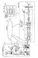
本発明の一実施形態に係るカラーマネジメント・システムは、例えば、図1に模式的に示すようなネットワーク環境において、インターネット26で相互に接続された複数のサイト17,21,25,30にまたがるサービスとして実現される。 The color management system according to the embodiment of the present invention is a service that spans a plurality of
コンテンツ制作サイト21では、複数のコンテンツ制作者が、スキャナ、デジタル・スチル・カメラ(DSC)等から取り込んだ写真画像やCG・イラスト等(以下では、これらをコンテンツと総称する)をPC(パーソナルコンピュータ)18,40,41などで現像・編集したり、これらPCのモニタや当該サイト内のプリンタ42で確認出力を行ったり、完成したコンテンツをサーバサイト30のリソースDB(データベース)28にアップロードしたりする。また、コンテンツ制作サイト21では、後述のプロファイル編集や、コンテンツへのプロファイルの割り付け(関連付け)を行うことができる。このようなコンテンツ制作サイト21は、物理的に一つの執務空間に限定されるものではなく、例えばPC18が、PC40,41とは別オフィスに存在したり、遠隔地で使用されるモバイルPCであったりするような場合もあり得る。 In the
出力サイト17は、オフセット印刷機43や、レーザプリンタ44、インクジェット・プリンタ45等、さまざまな出力装置で構成され、編集サイト25からの印刷要求に従って印刷出力を行う。これらの出力装置は、同じ部屋や建物内に設置される場合もあるし、遠隔地に分散して設置される場合もある。 The
編集サイト25では、リソースDB28に蓄積されたコンテンツを素材として原稿編集を行い、編集した原稿の印刷要求を出力サイト17に対し発行して印刷させることができる。編集サイト25では、出力サイト17の各出力装置43,44,45や、コンテンツ制作サイト21のプリンタ42やPC41のモニタなどの出力装置群から選択される出力装置を考慮したPCS(Profile Connection Space)の生成・編集を行い、このPCSをサーバサイト30のプロファイルDB(図2)に登録するとともに、該PCSの識別情報をコンテンツ制作サイト21に配信することができる。編集サイト25においても、プロファイルの編集とコンテンツへの割り付け(関連付け)を行うことができる。 The
ここで、PCSとは、Lab,XYZ等のデバイス非依存の色空間の部分空間である。また、プロファイルとは、前述したICCプロファイルのように、特定のデバイスに関連して、RGBやCMYKのようなデバイス固有の色パラメータをPCSの値に変換するための色変換パラメータと、その逆にPCSの値をデバイス固有の色パラメータに変換するための色変換パラメータ、および、PCS内で、そのデバイスが出力可能な色の範囲を示す色域(Gamut)情報をパッケージ化したものを指す。 Here, PCS is a partial space of a device-independent color space such as Lab or XYZ. A profile is a color conversion parameter for converting device-specific color parameters such as RGB and CMYK into PCS values in relation to a specific device, as in the ICC profile described above, and vice versa. This refers to a package of color conversion parameters for converting PCS values into device-specific color parameters and color gamut information indicating the range of colors that can be output by the device in the PCS.
RGBプロファイルはRGBを入力パラメータとするデバイスに関するプロファイルであり、同様にCMYKプロファイルはCMYKを入力パラメータとするプロファイルである。プリンタのように出力色が用紙に依存するデバイスの場合、色再現特性の異なる設定用紙毎にプロファイルが必要となることから、出力側の色変換パラメータであるプロファイルを用紙プロファイルと呼ぶことがある。入力側の色変換パラメータであるプロファイルは、実際の出力デバイスとは異なるデバイス特性による色再現特性を規定していることから、シミュレーションプロファイルと呼ぶことがある。 The RGB profile is a profile relating to a device having RGB as an input parameter, and similarly, the CMYK profile is a profile having CMYK as an input parameter. In the case of a device whose output color depends on paper, such as a printer, a profile is required for each set paper having different color reproduction characteristics. Therefore, a profile that is a color conversion parameter on the output side may be referred to as a paper profile. A profile that is a color conversion parameter on the input side is sometimes called a simulation profile because it defines color reproduction characteristics based on device characteristics different from those of an actual output device.
以下では説明を簡易にするため、PCSの表色系としてCIE1976Labを用い、その色空間の部分空間をPCSとして扱う。ただし、プロファイルをICCのものに限定しなければ、PCSの表色系として、Lab、XYZの他、CIECAM02のJChや、IPTなどを用いることもできる。JChやIPTを用いると、計算処理は煩雑になるものの色変換に伴う色相の保存性(特に青紫周辺での色相保存性)が良好になるという利点がある。 In the following, in order to simplify the explanation, CIE1976Lab is used as the color system of PCS, and a partial space of the color space is treated as PCS. However, if the profile is not limited to that of ICC, CIECAM02 JCh, IPT, or the like can be used in addition to Lab and XYZ as the PCS color system. When JCh or IPT is used, although the calculation process is complicated, there is an advantage that hue preservation with color conversion (particularly hue preservation around blue-violet) is improved.
図2は、本実施形態に係るカラーマネジメント・システムの処理説明図である。図2を参照し、CMYK画像を入力データとする画像出力装置(例えばCMYKレーザプリンタ)を出力デバイスとして選択した場合を例に、カラーマネジメント処理について、プロファイルと関連させて説明する。 FIG. 2 is a process explanatory diagram of the color management system according to the present embodiment. With reference to FIG. 2, color management processing will be described in relation to a profile, taking as an example a case where an image output apparatus (for example, a CMYK laser printer) that uses CMYK images as input data is selected as an output device.
出力サイト17において、画像出力デバイス11(ここでは例えばCMYKレーザプリンタ)に接続された画像処理装置のRIP(Raster Image Processor)2により、編集サイト25で編集された原稿画像データ1は画像出力デバイス11の解像度に合わせたビットマップデータに展開される。 At the
原稿画像データ1に埋め込まれたRGB画像データ19のビットマップデータは、RGB画像データ19に予め関連づけられたRGBプロファイル20に従って、RGB→PCS変換3により、設定されたPCSの範囲内に形成されるRGB色域5上のLab値に変換される。また、原稿画像データ1中のCMYKデータ24のビットマップデータは、CMYK画像データ24に予め関連づけられたCMYKプロファイル23に従って、CMYK→PCS変換4により、設定されたPCS内に形成されるCMYK色域6上のLab値に変換される。 The bitmap data of the
ここで、RGB→PCS変換3では、RGBからLabへの色変換と同時にPCSの範囲内への色域圧縮が行われる。そして、変換後のRGB色域5はRGB画像データ19の元の色域をPCSとの共通部分に制限したものである。同様に、CMYK→PCS変換4では、CMYKからLabへの色変換と同時にPCSの範囲内への色域圧縮が行われ、この変換後の色域6はCMYK画像データ23の元の色域をPCSとの共通部分に制限したものである。 Here, in RGB →
RGB色域5上のLab値とCMYK色域6上のLab値はそれぞれ、GMA(色域圧縮方法)7,8により、画像出力デバイス11の用紙設定に合わせたCMYK色域9の範囲に写像(色域圧縮)される。CMYK色域9の範囲に写像された2種類の画像のLabデータは、PCS→CMYK変換10によりCMYK面順次データへと展開・合成されて画像出力デバイス11へ入力され、画像出力デバイス11により出力画像12として出力される。GMA7,8の制御パラメータ、CMYK色域9の情報、PCS→CMYK変換10の色変換パラメータは、用紙プロファイルDB13から選択された用紙プロファイル14で与えられる。なお、GMA7とGMA8は同一のものであっても良い。 The Lab value on the RGB color gamut 5 and the Lab value on the
以上に説明したPCSを仲介した一連の色変換処理を行う色変換手段16は、図2ではRIP2の後段の独立した処理手段として示されている。しかし、色変換手段16の処理をRIP2における処理の中に組み込んで、RIP処理過程中のカラー値に対して実施するようにしてもよく、そのほうが一般的に処理効率は良い。 The color conversion means 16 for performing a series of color conversion processes mediated by the PCS described above is shown as an independent processing means subsequent to the
用紙プロファイル14は、画像出力デバイス11に近いサイトのDB(データベース)である用紙プロファイルDB13に保持されているが、同一機種が異なるサイトで運用されている場合など、汎用性の高い用紙プロファイルがある場合には、共有DBであるサーバサイト30のプロファイルDB29との間でプロファイル情報の同期をとる処理が行われる。 The paper profile 14 is held in the
編集サイト25では、原稿画像データ1のCMYKデータ24に対して、CMYK値に対応するデバイス非依存のカラー値(本例の場合Lab値)を規定するために、ユーザが適切なシミュレーションプロファイル(ここではCMYKプロファイル)23の割り付けを行う。ユーザがこの割り付けを行わない場合には、予め定められたデフォルトプロファイル(例えば、Japan-Color 2001 Coated)がシミュレーションプロファイル23に割り付けられる。ただし、正確には、これらのシミュレーションプロファイルとして、後述するように、設定されたPCSに応じて色変換パラメータが修正(編集)されたものが使用される。 In the
また、編集サイト25の特権ユーザは、前述のように色変換手段16における色変換処理に適用されるPCSの作成(生成・編集)を行うことができる。そして、そのPCSを、サーバサイト30の共有DBであるプロファイルDB29にアップロードするとともに、コンテンツ制作サイト21のコンテンツ制作者に通知することができる。 Further, the privileged user of the
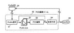
図3は、PCS編集ツールの機能的構成及び処理フローを説明するためのブロック図である。図3において、50はPCS編集ツールであり、これはサーバサイト30のアプリケーション・サーバ27から提供されて編集サイト25のPC22上で動作する。編集サイト25の特権ユーザは、このPCS編集ツール50を利用しPCSの作成(生成・編集)を行うことができる。 FIG. 3 is a block diagram for explaining the functional configuration and processing flow of the PCS editing tool. In FIG. 3,
PCS編集ツール50において、プロファイル選択手段51は、ユーザが、プロファイルDB29に登録されているプロファイルの中から、出力ターゲットとして使用する複数の出力デバイスのプロファイルを選択するための手段である。これにより選択されたプロファイルのリスト52がPCS編集処理手段53に入力される。ここで、出力デバイスの選択においては、用紙プロファイル毎に別々の出力デバイスが存在するものとして扱われる。より一般化するならば、使用される用紙や色材(インク、トナー)等の選択により出力条件が変化する画像出力装置の場合、出力条件に対応して用意されたプロファイル毎に別々の出力デバイスがあるものとして扱われる。また、プロファィル選択手段51で、ある出力デバイスのプロファイルを選択したということは、その出力デバイスを選択したことでもある。よって、プロファイル選択手段51は出力デバイスの選択手段でもある。 In the
PCS編集処理手段53において、プロファイル・リスト52から当該選択された複数の出力デバイスの色域情報を取得し、それら複数の色域に基づいて、ユーザの選択した又はデフォルト設定のPCS生成戦略(後述)に対応した所定のPCS生成方法によりPCSを自動生成する。ユーザは、PCS編集処理手段53により、自動生成されたPCSの形状編集(後述)を行うことができる。このようにして作成されたPCSは、配信手段54を通じてプロファイルDB29に登録されるとともに、そのPCSの識別情報がコンテンツ制作サイト21の各コンテンツ制作者に通知される。 In the PCS editing processing means 53, the gamut information of the selected output devices is obtained from the
なお、プロファイル選択手段51でプロファイルの代わりに既登録のPCSを選択することも可能である。この場合には、プロファイル・リスト52の生成とPCS編集処理手段53の処理はスキップされ、選択した既登録PCSの識別情報が配信手段54からコンテンツ制作サイト21の各制作者に通知される(該PCSの実体はプロファイルDB29にある)。 Note that the registered PCS can be selected by the profile selection means 51 instead of the profile. In this case, the generation of the
図4は、プロファイル編集ツールの機能的構成や、コンテンツ制作サイト21でのプロファイルの編集、コンテンツへのプロファイルの割り付け等の処理を説明するためのブロック図である。図4において、60はプロファイル編集ツールであり、これはサーバサイト30のアプリケーション・サーバ27から提供されてコンテンツ制作サイト21のPC18上で動作する。 FIG. 4 is a block diagram for explaining processing such as functional configuration of the profile editing tool, profile editing at the
編集サイト25から通知されたPCS識別情報は受信手段61で受け取られる。このPCS識別情報に基づきPCS取得手段62がプロファイルDB29から該当のPCSの情報(PCSの実体)を取得する。このようにして、受信したPCS識別情報に対応したPCSがプロファイル編集ツール60にデフォルト設定される。ただし、後述のように、ユーザはファイルブラウザ(不図示)を利用し、プロファイルDB29に登録されている任意のPCSを検索し設定することもできる。 The PCS identification information notified from the
コンテンツ制作サイト21のユーザは、プロファイル抽出手段63によって、編集対象のプロファイルを抽出することができる。ここでは、RGB画像データ19よりRGBプロファイル64が抽出されるが、RGB画像データ19にプロファイルが割り付けられていないときは、デフォルトとしてsRGB特性に基づくsRGBプロファイルで代用される。なお、後述するように、ユーザはファイルブラウザ(不図示)を利用し、プロファイルDB29に登録されているプロファイルを検索し、そのプロファイルを編集対象とすることもできる。 The user of the
ユーザは、GMAパラメータ編集手段68によって、RGB画像データ19の色域を、設定されたPCSの範囲内に制限する色域圧縮の編集を行うことができる(この編集の詳細については後述)。この編集の結果は、色域圧縮の制御パラメータであるGMAパラメータ69としてGMA66に渡される。GMAパラメータ編集手段68では、編集したGMAパラメータをGMAパラメータDB70へ保存したり、GMAパラメータDB70に保存されているGMAパラメータを再利用したりすることができる。 The user can edit the color gamut compression to limit the color gamut of the
GMA66では、GMAパラメータ69に基づいて、編集対象プロファイルであるRGBプロファイル64を、設定されたPCS内の色域内にLab値をもつRGBプロファイル20に変換する処理が行われる。この変換後のRGBプロファイル20では、色域が、設定されたPCSの範囲内に制限するように修正され、この修正された色域に合わせるようにRGB→PCS変換及びPCS→RGB変換の色変換パラメータが修正される。すなわち、GMA66は、ユーザによる色域圧縮の編集結果であるGMAパラメータ69に応じて、RGB画像データの色域を、設定されたPCSの範囲内に制限するように色変換パラメータを修正する手段である。 In the
コンテンツ制作サイト21のユーザは、修正(編集)されたRGBプロファイル20をユーザアプリケーション67に設定して画像編集を行うことができる。そして、編集後のRGB画像データ19を、それにRGBプロファイル20を関連づけて、サーバサイト30のリソースDB28にアップロードすることができる。 The user of the
以上、コンテンツ制作サイト21でのRGBプロファイルの修正(編集)について説明した。 The correction (editing) of the RGB profile at the
編集サイト25においても、プロファイル編集ツール60を利用し、CMYKプロファイルに対し、設定したPCSに応じた同様の修正(編集)を行うことができる。すなわち、編集サイト25のユーザは、アプリケーション・サーバ27から提供されるプロファイル編集ツール60をPC22上で動作させ、設定したいPCSをプロファイルDB29よりダウンロードし、また、編集対象プロファイルであるCMYKプロファイルをプロファイルDB29よりダウンロードする。そして、このCMYKプロファイル23に対し、色域を、設定したPCSの範囲内に制限する修正を施し、修正したCMYKプロファイルをCMYK画像データ24に割り付ける処理を行う。このプロファイル割付処理は、アプリケーション・サーバ27から提供されるドキュメント編集ツール(不図示)を使用する場合には自動設定される。 In the
以上に説明したように、PCS編集ツール50を利用し、ユーザは、選択可能な複数の出力デバイスの中から任意の複数の出力デバイスを選択し、それら出力デバイスのプロファイルの色域情報を取得し、それら色域に基づき所定のPCS生成方法によりPCSを生成し、必要に応じてPCSの形状を編集する。このようにして作成されたPCSをプロファイル編集ツール60に設定する。そして、ユーザはRGBプロファイル、CMYKプロファイルの色変換パラメータを、色域が、設定したPCSの範囲内に制限されるように修正し、修正後のプロファイルを原稿画像データ1のRGB画像データとCMYK画像データにそれぞれ関連づける。かくして、図2の色変換手段16において、ユーザが選択した複数の出力デバイスの色域に基づいて作成されたPCSを適用した色変換処理を行わせることができる。 As described above, using the
次に、ユーザインタフェースと関連させて、PCS編集ツール及びプロファイル編集ツールについてより詳細に説明する。 Next, the PCS editing tool and the profile editing tool will be described in more detail in relation to the user interface.
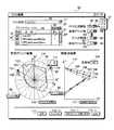
図5にPCS編集ツール50のユーザインタフェース画面の例を示す。ユーザは、まずPCS編集ツール50のユーザインタフェース画面上のPCS名称表示部76に、これから作成するPCSの名称を入力する。未入力の場合のデフォルト名称は“名称未設定”になっている。 FIG. 5 shows an example of a user interface screen of the
なお、図3に関連して、プロファイル選択手段51でプロファイルDB29に既登録のPCSを選択してコンテンツ制作サイト21のユーザへ通知することも可能であると説明した。ここで説明する態様においては、ユーザが選択ボタン77を押下することでファイルブラウザ(図示せず)を起動し、該ファイルブラウザを用いてプロファイルDB29内の既登録のPCSを選択し、そのPCSの名称をPCS名称表示部76に設定させることができる。つまり、ここでは図3のプロファイル選択手段51により既登録PCSを選択する機能を、ファイルブラウザを利用して実現する。ただし、これはあくまで一例にすぎない。そして、ユーザインタフェース画面の下部右端の配信ボタン114を押下することにより、設定した既登録PCSを配信することができる。 In connection with FIG. 3, it has been described that the profile selection means 51 can select a PCS already registered in the
さて、複数の出力デバイスの色域に基づいて新たなPCSを生成する場合、その複数の出力デバイスのプロファイルを選択する(ここで、前述したように各用紙プロファイルは一つの出力デバイスとして扱われる)。このプロファイル選択に関連して、ユーザインタフェース画面上にプロファイル・リスト表示部78と、追加ボタン82、削除ボタン83が設けられている。 When a new PCS is generated based on the color gamuts of a plurality of output devices, the profiles of the plurality of output devices are selected (here, as described above, each paper profile is handled as one output device). . In relation to this profile selection, a profile /
プロファイル・リスト表示部78に表示される各エントリは、チェックボックス79、プロファイル名称80、重み係数81で構成される。チェックボックス79は、エントリの有効/無効を指定するスイッチである。チェックボックス79がチェックされているエントリのみが、以下の編集操作対象として有効となり、チェックの外されたエントリは、プロファイル・リスト表示部78に表示されるだけで、以下の処理対象としては無効化される。すなわち、プロファイル・リスト表示部78に表示されたプロファイル・リストにおいて、チェックボックス79がチェックされているプロファイルのみが有効である。この有効なプロファイルが、図3のプロファイル選択手段51で選択されたプロファイルに相当し、図3のプロファイル・リスト52を構成するプロファイルに相当する。また、重み係数81は、0以上の整数値を指定可能であり、後述する加重平均処理の重み係数として使用される。 Each entry displayed in the profile
初期状態では、プロファイル・リスト表示部78は空欄である。ユーザは、追加ボタン82を押下してファイルブラウザ(図示せず)を起動し、このファイルブラウザを利用してプロファイルDB29内の出力デバイスのプロファイルを選択して、そのエントリをプロファイル・リストに追加することができる。既存エントリを削除したい場合、ユーザは削除対象とするプロファイル名称を押下して選択状態とした上で削除ボタン83を押下すればよい。 In the initial state, the profile
このように、ここで説明する態様においては、プロファイル・リスト表示部80とそのチェックボックス79、追加ボタン82、削除ボタン83、追加ボタン82を押すと起動するファイルブラウザ等によって、PCSを生成・編集するための出力デバイスのプロファイルを選択するプロファイル選択手段51の機能が実現される。ただし、これはあくまで一例である。 As described above, in the embodiment described here, the PCS is generated and edited by the profile /
図5の例では、プロファイル・リスト表示部78にプロファイル名称が表示されているプロファイルのうち、チェックボックスがチェックされている”myLCD”、”PPColorLaserMatte”という名称の2つのプロファイルが、PCSの生成・編集のためのプロファイルとして選択されている。後の説明では、”myLCD”に対応する色域を第1の色域、”PPColorLaserMatte”に対応する色域を第2の色域と呼ぶ。 In the example of FIG. 5, among the profiles whose profile names are displayed in the profile
なお、ここではPCSの生成・編集に2つの出力デバイスの色域を用いるものとして説明するが、3つ以上の出力デバイスの色域を用いることも可能である。また、第1の色域をRGBモニタ系の色域、第2の色域をプリンタ系の色域としたのは、単に差の大きな色域を例にした方が説明が分かりやすいという理由からであって、PCS作成に利用する出力デバイスの組み合わせは基本的に任意である。 Note that, here, it is assumed that the color gamuts of two output devices are used for PCS generation / editing, but the color gamuts of three or more output devices can also be used. In addition, the reason why the first color gamut is the RGB monitor gamut and the second color gamut is the printer gamut is because the explanation is easier to understand by simply taking the color gamut having a large difference as an example. The combination of output devices used for PCS creation is basically arbitrary.
図5の説明に戻る。ユーザインタフェース画面において、PCS生成戦略表示部85には、ユーザが選択ボタン86を押下することで表示される選択肢87の中からユーザによって選択されたPCS生成戦略が表示される。PCS生成戦略は、複数の色域に基づいてPCSを自動生成する所定のPCS生成方法に付けられた名称である。本実施形態では、PCS生成方法として、”平均”、”共通”、”包含”の3つの方法が予め用意され、ユーザが任意に選択可能である。ここでは、”平均”がデフォルトのPCS生成戦略とされている。 Returning to the description of FIG. In the user interface screen, the PCS generation
色相グリッド数表示部88には、ユーザが選択ボタン89を押下することで表示される選択肢(図示せず)の中からユーザにより選択された値が表示される。色相グリッド数の選択肢には、12,18,24,36があり、そのデフォルト値は24である。 The hue grid
グリッド間隔表示部91には、ユーザが選択ボタン92を押下することで表示される選択肢(図示せず)の中からユーザにより選択された値が表示される。色相グリッド間隔の選択肢には、30°,20°,15°,10°があり、そのデフォルト値は15°とされている。なお、色相グリッド数とグリッド間隔値は連動しており、一方の値を変更すると他方の値も対応した値に自動的に修正される。 In the grid interval display unit 91, a value selected by the user from options (not shown) displayed when the user presses the selection button 92 is displayed. The hue grid spacing options include 30 °, 20 °, 15 °, and 10 °, and the default value is 15 °. Note that the number of hue grids and the grid interval value are linked, and when one value is changed, the other value is automatically corrected to a corresponding value.
彩度グリッド数表示部93には、ユーザが選択ボタン94を押下することで表示される選択肢(図示せず)の中からユーザにより選択された値が表示される。彩度グリッド数の選択肢には、3,4,5,6があり、そのデフォルト値は4とされている。 The saturation grid
色相グリッド数および彩度グリッド数は、PCS編集ツール50のユーザインタフェース画面に色相グリッド編集に関連して表示されるグリッドの初期値となる。 The number of hue grids and the number of saturation grids are initial values of grids displayed on the user interface screen of the
Lab空間の部分空間であるPCSは、プロファイル・リストで有効指定された出力デバイスのプロファイルの色域に基づいて、PCS生成戦略表示部85に表示されたPCS生成戦略に対応した所定のPCS生成方法により自動生成される。ユーザは、自動生成されたPCSの形状を編集することもできる。このようなPCSの自動生成のための処理手段とPCSの形状編集のための処理手段は、前述のようにPCS編集処理手段53に含まれている。 The PCS that is a subspace of the Lab space is a predetermined PCS generation method corresponding to the PCS generation strategy displayed on the PCS generation
PCS生成戦略に従うPCSの自動生成と、生成されたPCSの形状編集について、ユーザインタフェースと関連させてさらに説明する。 The automatic generation of the PCS according to the PCS generation strategy and the editing of the shape of the generated PCS will be further described in relation to the user interface.
PCS編集ツール50のユーザインタフェース画面において、左下部分にあるa−b平面図118には、Lab空間のa−b平面上に投影した第1の色域102と第2の色域103が表示される。円環95は、色相方向の分割位置を定める制御点97を有している。この制御点97は、前述した色相グリッド数表示部88、あるいはグリッド間隔表示部91で指定した値に対応するものが表示される。円環95上の黒点で示した制御点97は、マウスポインタで円環95に沿って移動させることが可能であり、移動した角度はインジケータ115に表示される。また、円環95上の制御点以外の位置でマウスを右クリックすることで、追加インジケータ98が表示され、制御点が追加される。なお、追加インジケータ98からマウスカーソルを外すと追加操作はキャンセルされる。逆に、円環95上の制御点上でマウスを右クリックすると、削除インジケータ99が表示され、その制御点が削除される。削除インジケータ99からマウスカーソルを外すと、削除操作はキャンセルされる。 On the user interface screen of the
初期化ボタン116を押下することにより、これら円環95上のグリッドに施した編集をキャンセルし、グリッド状態を色相グリッド数表示部88(あるいはグリッド間隔表示部91)で指定されたグリッド状態に戻すことができる。 When the initialization button 116 is pressed, the editing performed on the grids on the
また、円環上に二重丸で示した編集色相指示マーカ101は、ユーザインタフェース画面の右下部分に示したLab空間のC−L断面119に表示される色相を指示するものである。C−L断面図119の色相角表示部104には、この編集色相指示マーカ101に連動して色相角が表示される。そして、この色相角での第1の色域105と第2の色域107の断面図がC−L断面図119上に表示される。 An edit
また、それぞれの色域の最大彩度点108,110を基準として、彩度を彩度グリッド表示部93で指定されたグリッド数等分した色域境界位置に、それぞれの基準制御点が配置される。図5のC−L断面図119では、第1の色域105の境界上の制御点は白丸印(○)で示されており、また、第2の色域107上の制御点は白三角印(△)で示されている。 Further, the respective reference control points are arranged at the color gamut boundary positions obtained by dividing the saturation by the number of grids designated by the saturation
PCS生成戦略表示部85に表示されているPCS生成戦略が”平均”の場合、第1と第2の色域の対応する制御点(図では線分で連結して表示)の重心(即ち加重平均)を初期値として、この色相でのPCS断面106を規定する制御点(●印)が表示される。つまり、PCS生成戦略が”平均”の場合、2つの色域に基づいて自動生成されるPCSの境界を特徴付ける制御点は、第1の色域と第2の色域の対応した制御点を”加重平均”したものである。そして、生成されたPCSの当該色相での境界上の制御点が表示される。 When the PCS generation strategy displayed on the PCS generation
上記加重平均の重み係数として、プロファイル・リスト表示部78で指定された重み係数81が使用される。重み係数81は、加重平均計算に先立って、プロファイル・リストの有効エントリの重み係数の総和が1となるよう予め正規化して使用される。 As the weighted average weighting factor, the
PCS断面106の制御点(●)は、マウスを用いて移動させることができる。さらに、色相環グリッド編集と同様に、PCS断面106上でマウスを右クリックすることで、制御点を追加・削除することができる。このような制御点操作によって、第1と第2の色域の加重平均により生成されたPCSの形状を編集することができる。これらの編集結果をリセットする場合、リセットボタン117を押下することで、制御点は初期値(対応する○と△の重心)に戻される。 The control point (●) of the
ユーザがPCS生成戦略として選択肢87の中の”共通”を選択した場合のC−L断面図119の例を図6に示す。このPCS生成戦略で自動生成されるPCSの断面106は、当該色相における第1の色域105と第2の色域107の共通部分として定義される。また、制御点(●)は、PCS断面106の最大彩度点109の彩度を彩度グリッド数表示部93に指定された数だけ等分した彩度上の境界に配置される。すなわち、第1と第2の色域の共通部分がPCSとして生成される。このPCSに対しても、”平均”の場合と同様の形状編集が可能である。 FIG. 6 shows an example of a C-L
ユーザがPCS生成戦略として選択肢87中の“包含”した場合のC−L断面図119の例を図7に示す。このPCS生成戦略で自動生成されるPCSの断面106は、当該色相での第1の色域105の制御点(○)と第2の色域の制御点(△)をともに含むC*方向に凸な(PCS断面106の境界をL*の関数と見たときにC*が極小値を持たない)最小の多角形として定義される。この場合、PCS断面106の境界の頂点を構成する色域断面の制御点をPCS断面の制御点とする。すなわち、第1と第2の色域を包含する最小の色域がPCSとして生成される。このPCSに対しても形状編集が可能である。 FIG. 7 shows an example of a C-L
図5の説明に戻る。PCS編集ツール50のユーザインタフェース画面の最下段に、PCSの編集結果の保存を指示する保存ボタン111、編集結果のキャンセルを指示するキャンセルボタン112、最後に保存した編集結果に復帰する復帰ボタン113、および、配信ボタン114が配置されている。配信ボタン114が押下された場合、作成された編集結果が保存されるとともにサーバサイト30のプロファイルDB29に編集されたPCSがアップロードされ、また、配信先として登録されているユーザに対して当該PCSの識別情報が通知される。 Returning to the description of FIG. At the bottom of the user interface screen of the
図8に、プロファイル編集ツール60のユーザインタフェース画面の例を示す。プロファイル編集ツール60のユーザインタフェース画面上のプロファイル名称表示部125には、編集対象とするプロファイルの名称が表示される。対象とするプロファイルとして、図4に示したプロファイル抽出手段63により抽出されたプロファイル64又はプロファイルDB29に登録されているプロファイルを選択可能である。このプロファイルの選択は、選択ボタン126を押下して起動されるファィルブラウザ(図示せず)を利用して行われる。 FIG. 8 shows an example of a user interface screen of the
PCS名称表示部127には、設定されたPCSの名称が表示される。そのデフォルト値としては、図4の受信手段61で受信したPCS識別情報に従ってPCS取得手段62によりプロファイルDB29よりダウンロードされたPCSの名称が表示される。設定するPCSを変更したい場合、選択ボタン128を押下して起動されるファイルプラウザを利用し、プロファイルDB29に登録されているPCSの中から設定したいPCSを選択することができる。この場合、ファイルブラウザがPCS取得手段62として利用されるわけである。 In the PCS
GMA表示部129には、選択ボタン130を押下して表示される選択肢131中のいずれかのGMA名称が表示される。そのデフォルト値は“定点引き込み”である。 The
ユーザインタフェース画面上のa−b平面図118には、編集対象の入力プロファイルの色域境界と設定されたPCSの境界とが表示され、また、PCS編集ツール50で編集されたグリッドが表示される。破線で示されている入力プロファイルの色域境界136とグリッドとの交点(○印)が入力制御点である。入力制御点(○)に対応づけられるPCS境界135上の●印が出力制御点である。色相補正は、この出力制御点を調整することで行なわれる。例えば、入力制御点133に対応する出力制御点初期値は、同じ色相上の点(図8では黒ベタ△印の位置)だが、これをマウス用いて出力制御点134の位置にドラッグすることで、入力色相角315°の位置の制御点が色相角305°の色相のPCS境界に対応づけられる。このときの修正された色相角の情報は、制御点をドラッグしている間、インジケータ132に表示される。また、修正された対応する制御点は線分で連結表示される。 In the
一方、ユーザインタフェース画面上のC−L断面図119には、編集色相指示マーカ101で指示した入力プロファイルの色域断面139と、これに対応づけた出力制御点134でのPCS断面140が表示される。このときの入力プロファイルの色域断面139の色相角は色相角表示部137に、PCS断面140の色相角は色相角表示部138にそれぞれ表示される。 On the other hand, in the CL
入力プロファイル色域断面139の境界上の入力制御点(○)の初期配置は、色域の頂点141の彩度を彩度グリッド数表示部147で指示したグリッド数で分割した位置となる。グリッド数はPCS編集の場合と同様に選択ボタン148で変更可能となっている。また、これに対応づけられるPCS断面140の境界上の出力制御点(●)の初期値は、GMA表示部129に表示されたGMA名称によって異なる。 The initial arrangement of the input control points (◯) on the boundary of the input
GMA名称として“定点引き込み”が選択されている場合、L*軸上の定点149と入力制御点(○)とを結ぶ線分と、PCS断面140の境界との交点が出力制御点(●)の初期値となる。この出力制御点(●)は、PCS断面上であれば、マウスで移動させることにより調整可能である。図8の例では、頂点141に対応する出力制御点の初期位置142を出力制御点143に移動している。また、定点149もドラッグによる調整が可能であり、ドラッグ中はインジケータ144により明度が表示されるようになっている。 When “fixed point pull-in” is selected as the GMA name, the intersection of the line connecting the fixed
GMA名称の他の選択肢として、”色差最小”、”明度優先”、”彩度優先”がある。
”色差最小”が選択されている場合は、入力制御点に最も近いPCS断面140上の点が出力制御点の初期位置となる。“明度優先”が選択されている場合は、入力制御点(○)と等明度のPCS断面140の境界点(対応づけ可能な境界点が無い場合はL*軸上の点)が対応づけられる。“彩度優先”が選択されている場合は、入力制御点(○)と等彩度のPCS断面140の境界点で入力制御点(○)側に近い点(対応づけ可能な境界点が無い場合は出力制御点143)が対応づけられる。Other options for the GMA name include “minimum color difference”, “lightness priority”, and “saturation priority”.
When “minimum color difference” is selected, the point on the
入力制御点と出力制御点に対する操作によって、入力プロファイル色域を設定されたPCSの範囲内に制限する色域圧縮を編集することができる。各入力制御点には、それに対応する出力制御点の方向が規定される。これらの入力制御点と出力制御点への方向ベクトルが、図4のGMAパラメータ編集手段68からGMAパラメータ69としてGMA66へ渡され、GMA66において入力プロファイルの修正がなされる。 By operating on the input control points and the output control points, it is possible to edit the color gamut compression that limits the input profile color gamut within the set PCS range. For each input control point, the direction of the corresponding output control point is defined. Direction vectors to these input control points and output control points are passed from the GMA parameter editing means 68 of FIG. 4 to the
まず、PCS領域外にある入力プロファイル色域の一般の点Pに対する色相補正量は、Pを挟む入力制御点の色相補正量を補間(最も簡便には線形補間)で決定する。明度・彩度補正量に関しても、引き込み方向を線形補間することで引き込み方向が決定される。具体的には、”定点引き込み”の場合であれば、図9に示す様に、点Pを挟む入力制御点のC−L座標をP1,P2として、そこでの引き込み方向を示すC−L面内単位方向ベクトルを、それぞれu,v、線分P1P2と、定点144とPを結ぶ直線との交点をP’とするとき、tを、P’=(1−t)P1+tP2となるパラメータとしてu’=(1−t)u+tvとなるu’をPに対する引き込み方向とし、Pを通ってu’方向に向かう直線とPCS境界140との交点P”がPの対応点となる。その他のGMA名称が選択された場合への拡張方法は自明であるので、これ以上の説明は省略する。 First, the hue correction amount for a general point P in the input profile color gamut outside the PCS region is determined by interpolation (most simply, linear interpolation) at the input control points sandwiching P. Regarding the lightness / saturation correction amount, the pull-in direction is determined by linearly interpolating the pull-in direction. Specifically, in the case of “fixed-point pull-in”, as shown in FIG. 9, the CL plane of the input control point sandwiching the point P is set as P1 and P2, and the pull-in direction there is shown. Assuming that the intersection of the inner unit direction vectors u, v, line segment P1P2 and the straight line connecting fixed
このようにして、入力プロファイル色域をPCSの範囲内に圧縮する色域圧縮方法が確定すれば、入力プロファイルに含まれるデバイス色→PCS変換の色変換パラメータ、PCS→デバイス色変換の色変換パラメータ、色域情報を、設定されたPCSに対応するものに容易に修正することができる。この場合、修正された色域情報は、もとの入力プロファイル色域を設定されたPCSとの共通部分に制限したものとなる。 If the color gamut compression method for compressing the input profile color gamut within the PCS range is determined in this way, the device color → PCS conversion color conversion parameter and PCS → device color conversion color conversion parameter included in the input profile. The color gamut information can be easily corrected to the one corresponding to the set PCS. In this case, the corrected color gamut information is obtained by limiting the original input profile color gamut to a common part with the set PCS.
以上に説明した実施形態には、次に列挙するようなカラーマネジメント・システムが包含されている。 The embodiments described above include color management systems as listed below.
<A> デバイス依存のカラー値で記述された入力画像データに対し、前記デバイス依存のカラー値をデバイス非依存のカラー値として解釈するための、前記入力画像データに関連づけられた入力側色変換パラメータと、前記デバイス非依存のカラー値を出力デバイスに依存したカラー値に対応づける出力側色変換パラメータとに基づいて、前記デバイス非依存のカラー値のなす色空間の部分領域(以下、PCSと記す)を仲介して、前記出力デバイスに応じた色変換処理を行う色変換処理手段を備えるカラーマネジメント・システムであって、
ユーザが、選択可能な複数の出力デバイスの中から複数の出力デバイスを選択するための出力デバイス選択手段と、
前記出力デバイス選択手段によってユーザが選択した複数の出力デバイスそれぞれの前記色空間における色再現可能範囲(以下、色域と記す)に基づいて、所定のPCS生成方法により前記PCSを自動生成するPCS生成手段とを備えることを特徴とするカラーマネジメント・システム。<A> Input-side color conversion parameter associated with the input image data for interpreting the device-dependent color value as a device-independent color value for input image data described with a device-dependent color value And a color space partial area (hereinafter referred to as PCS) formed by the device-independent color value based on the output-side color conversion parameter that associates the device-independent color value with the color value depending on the output device. ), And a color management system including color conversion processing means for performing color conversion processing according to the output device,
An output device selection means for the user to select a plurality of output devices from a plurality of selectable output devices;
PCS generation that automatically generates the PCS by a predetermined PCS generation method based on a color reproducible range (hereinafter referred to as a color gamut) in the color space of each of a plurality of output devices selected by the user by the output device selection unit A color management system comprising: means.
このような構成によれば、ユーザが出力ターゲットとする複数の出力デバイスを選択するだけで、それらの出力デバイスの色域に基づいた適切なPCSを設定可能となる。なお、上記色変換処理手段は、前記実施形態における色変換手段16に対応する。また、前記実施形態において、上記出力デバイス選択手段と上記PCS生成手段はそれぞれプロファイル編集ツール50に含まれる。 According to such a configuration, it is possible to set an appropriate PCS based on the color gamut of the output devices only by the user selecting a plurality of output devices as output targets. The color conversion processing unit corresponds to the
<B> 前記カラーマネジメント・システム(A)において、前記PCS生成手段により自動生成される前記PCSは、前記出力デバイス選択手段によってユーザが選択した前記複数の出力デバイスそれぞれの色域の共通部分より広いことを特徴とするカラーマネジメント・システム。 <B> In the color management system (A), the PCS automatically generated by the PCS generation unit is wider than a common part of the color gamut of each of the plurality of output devices selected by the user by the output device selection unit. A color management system characterized by this.
このような構成によれば、ユーザによって選択された出力デバイス中に色域の小さな出力デバイスが含まれている場合においても、PCSの矮小化を回避できる。前記実施形態において、PCS生成戦略として”平均”又は”包含”が選ばれた場合に、生成されるPCSはユーザに選択された出力デバイスそれぞれの色域の共通部分より広くなり、上記カラーマネジメント・システムBの構成が充足される。 According to such a configuration, even when an output device with a small color gamut is included in the output device selected by the user, it is possible to avoid a reduction in PCS. In the embodiment, when “average” or “include” is selected as the PCS generation strategy, the generated PCS is wider than the common part of the color gamut of each output device selected by the user, and the color management The configuration of system B is satisfied.
<C> 前記カラーマネジメント・システム(B)において、前記PCS生成手段により自動生成される前記PCSの境界を特徴付ける制御点は、前記出力デバイス選択手段によってユーザが選択した前記複数の出力デバイスそれぞれの色域の境界を特徴付ける制御点の加重平均で得られることを特徴とするカラーマネジメント・システム。 <C> In the color management system (B), the control point characterizing the boundary of the PCS automatically generated by the PCS generation means is the color of each of the plurality of output devices selected by the user by the output device selection means. A color management system characterized by a weighted average of control points that characterize the boundaries of a region.
このような構成は、前記実施形態においてPCS生成戦略として”平均”を選択した場合に相当する。この構成によって、選択された複数の出力デバイスの中の優先すべき出力デバイスの色域をPCSの生成において優先させることができる。 Such a configuration corresponds to the case where “average” is selected as the PCS generation strategy in the embodiment. With this configuration, it is possible to prioritize the color gamut of the output device to be prioritized among the plurality of selected output devices in the generation of the PCS.
<D> 前記カラーマネジメント・システム(C)において、前記PCS生成手段は前記加重平均の重み係数をユーザが編集するための手段を含むことを特徴とするカラーマネジメント・システム。 <D> In the color management system (C), the PCS generation means includes means for a user to edit the weighted average weight coefficient.
このような構成によれば、選択された複数の出力デバイスの中の優先すべき出力デバイスの色域をPCSの生成において優先させ、かつ、その優先度合をユーザが調整することができる。前記実施形態においては、上記重み係数を編集するための手段はPCS編集ツール50に含まれている。 According to such a configuration, the color gamut of the output device to be prioritized among the plurality of selected output devices can be prioritized in PCS generation, and the priority can be adjusted by the user. In the embodiment, the means for editing the weighting factor is included in the
<E> 前記カラーマネジメント・システム(A,B,C,D)のいずれかにおいて、前記PCS生成手段は自動生成したPCSの形状をユーザが編集するための手段を含むことを特徴とするカラーマネジメント・システム。 <E> In any of the color management systems (A, B, C, D), the PCS generation means includes means for the user to edit the automatically generated PCS shape. ·system.
このような構成によれば、ユーザはPCSの形状の微調整を容易に行うことができる。前記実施形態においては、上記PCS形状編集のための手段はPCS編集ツール50に含まれている。 According to such a configuration, the user can easily perform fine adjustment of the shape of the PCS. In the embodiment, the means for editing the PCS shape is included in the
<F> 前記カラーマネジメント・システム(A,B,C,D,E)のいずれかであって、前記入力画像データに関連づけられた入力側色変換パラメータを、前記入力画像データの前記色空間における色再現範囲(以下、色域と記す)が前記PCSの範囲に制限されるように修正する色変換パラメータ修正手段をさらに備えることを特徴とするカラーマネジメント・システム。 <F> In any one of the color management systems (A, B, C, D, E), an input side color conversion parameter associated with the input image data is set in the color space of the input image data. A color management system, further comprising color conversion parameter correction means for correcting a color reproduction range (hereinafter referred to as a color gamut) to be limited to the PCS range.
このような構成によれば、協業するワークグループメンバが編集する画像データの色域を共有すべきPCSの範囲内に制限することが可能となる。前記実施形態において、上記色変換パラメータ修正手段はプロファイル編集ツール60に含まれている。 According to such a configuration, it becomes possible to limit the color gamut of the image data edited by the collaborating workgroup members within the range of the PCS to be shared. In the embodiment, the color conversion parameter correction means is included in the
<G> 前記カラーマネジメント・システム(F)であって、前記入力画像データの色域を前記PCSの範囲に制限する色域圧縮をユーザが編集するための色域圧縮編集手段を備え、該色域写像編集手段によって編集された色域写像の制御パラメータに基づいて、前記色変換パラメータ修正手段は前記入力側色変換パラメータを修正することを特徴とするカラーマネジメント・システム。 <G> The color management system (F), comprising color gamut compression editing means for a user to edit color gamut compression that limits the color gamut of the input image data to the range of the PCS. A color management system, wherein the color conversion parameter correction unit corrects the input side color conversion parameter based on a control parameter of the color gamut map edited by the gamut mapping editing unit.
このような構成によれば、協業するワークグループメンバが編集する画像データの色域を、共有すべきPCSの範囲内に制限する方法を容易に最適化することができる。前記実施形態において、上記色域圧縮編集手段は前記プロファイル編集ツール60の含まれている。 According to such a configuration, it is possible to easily optimize the method for limiting the color gamut of the image data edited by the collaborating workgroup members within the range of the PCS to be shared. In the embodiment, the color gamut compression editing means includes the
<H> デバイス依存のカラー値で記述された入力画像データに対し、前記デバイス依存のカラー値をデバイス非依存のカラー値として解釈するための、前記入力画像データに関連づけられた入力側色変換パラメータと、前記デバイス非依存のカラー値を出力デバイスに依存したカラー値に対応づける出力側色変換パラメータとに基づいて、前記デバイス非依存のカラー値のなす色空間の部分領域(以下、PCSと記す)を仲介して、前記出力デバイスに応じた色変換処理を行う色変換処理手段を備えるカラーマネジメント・システムであって、
ユーザが、選択可能な複数の出力デバイスの中から複数の出力デバイスを選択するための出力デバイス選択手段と、
前記出力デバイス選択手段によってユーザが選択した複数の出力デバイスそれぞれの前記色空間における色再現可能範囲(以下、色域と記す)に基づいて、所定のPCS生成方法により前記PCSを自動生成するPCS生成手段と、
前記出力側色変換パラメータ及び前記PCSを保持する、ネットワークに接続されたサーバとを備え、
前記サーバに保持された前記出力側色変換パラメータ及び前記PCSを複数のユーザでネットワークを介して共有することを特徴とするカラーマネジメント・システム。<H> Input-side color conversion parameter associated with the input image data for interpreting the device-dependent color value as a device-independent color value for input image data described with a device-dependent color value And a color space partial area (hereinafter referred to as PCS) formed by the device-independent color value based on the output-side color conversion parameter that associates the device-independent color value with the color value depending on the output device. ), And a color management system including color conversion processing means for performing color conversion processing according to the output device,
An output device selection means for the user to select a plurality of output devices from a plurality of selectable output devices;
PCS generation that automatically generates the PCS by a predetermined PCS generation method based on a color reproducible range (hereinafter referred to as a color gamut) in the color space of each of a plurality of output devices selected by the user by the output device selection unit Means,
A server connected to a network that holds the output side color conversion parameters and the PCS;
A color management system, wherein the output side color conversion parameter and the PCS held in the server are shared by a plurality of users via a network.
このような構成よれば、色変換処理のPCSを予め固定的に用意されたものにのみ限定せず、ユーザが出力ターゲットとする出力デバイスを選択する都度、その出力デバイスの組み合わせに応じたPCSを生成し、このPCSをネットワークを介して協業するワークグループメンバ間で容易に共有することができる。なお、上記色変換処理手段は前記実施形態における色変換手段16に対応し、また、前記実施形態において上記出力デバイス選択手段と上記PCS生成手段はそれぞれプロファイル編集ツール50に含まれている。 According to such a configuration, the PCS for color conversion processing is not limited to those fixedly prepared in advance, and whenever the user selects an output device as an output target, the PCS corresponding to the combination of the output devices is selected. This PCS can be easily generated and shared among workgroup members collaborating via a network. The color conversion processing means corresponds to the color conversion means 16 in the embodiment. In the embodiment, the output device selection means and the PCS generation means are respectively included in the
<I> 前記カラーマネジメント・システム(H)であって、ネットワークに接続されたアプリケーション・サーバをさらに備え、前記出力デバイス選択手段及び前記PCS生成手段はネットワークに接続されたユーザPCに対して前記アプリケーション・サーバより提供されることを特徴とするカラーマネジメント・システム。 <I> The color management system (H), further comprising an application server connected to a network, wherein the output device selection unit and the PCS generation unit are configured to apply the application to a user PC connected to the network. A color management system characterized by being provided by a server.
このような構成によれば、ワークグループのメンバ間でのPCS生成手段のバージョン不整合や、それに起因したPCSの不一致等を容易に回避できる。 According to such a configuration, it is possible to easily avoid the version mismatch of the PCS generation means among the members of the work group, the PCS mismatch caused by the mismatch, and the like.
<J> 前記カラーマネジメント・システム(H)であって、前記入力画像データに関連づけられた入力側色変換パラメータを、前記入力画像データの前記色空間における色再現範囲(以下、色域と記す)が前記PCSの範囲に制限されるように修正する色変換パラメータ修正手段と、ネットワークに接続されたアプリケーション・サーバとをさらに備え、前記出力デバイス選択手段、前記PCS生成手段及び前記色変換パラメータ修正手段はネットワークに接続されたユーザPCに対して前記アプリケーション・サーバより提供され、前記PCS生成手段は生成したPCSを複数のユーザに通知する手段を含み、前記PCS生成手段により通知されたPCSが前記色変換パラメータ修正手段にデフォルト設定されることを特徴とするカラーマネジメント・システム。 <J> In the color management system (H), an input-side color conversion parameter associated with the input image data is a color reproduction range (hereinafter referred to as a color gamut) in the color space of the input image data. Further comprising: a color conversion parameter correcting unit that corrects the PCS to be limited to the PCS range; and an application server connected to the network, the output device selecting unit, the PCS generating unit, and the color conversion parameter correcting unit. Is provided from the application server to a user PC connected to the network, and the PCS generation means includes means for notifying a plurality of users of the generated PCS, and the PCS notified by the PCS generation means is the color. Color characterized by default setting for conversion parameter correction means Nejimento system.
このような構成によれば、ワークグループのメンバそれぞれのPCS設定作業が自動化されるためPCS誤設定が起きにくくなる。ワークグループメンバが編集する画像データの色域を共有すべきPCSの範囲内に制限することが可能となる。ワークグループのメンバ間でのPCS生成手段のバージョン不整合や、それに起因したPCSの不一致等を容易に回避できる。前記実施形態において、上記色変換パラメータ修正手段はプロファイル編集ツール60に含まれており、上記PCSを複数のユーザに通知する手段はPCS編集ツール50に含まれている。 According to such a configuration, the PCS setting work for each member of the work group is automated, so that it is difficult for PCS misconfiguration to occur. It becomes possible to limit the color gamut of the image data edited by the work group member within the range of the PCS to be shared. It is possible to easily avoid inconsistencies in the version of the PCS generation means among the members of the work group and inconsistencies in the PCS caused by the inconsistency. In the embodiment, the color conversion parameter correcting means is included in the
なお、本発明は、以上に説明した態様のみに限定されるものではなく、様々な変形もしくは修正した態様も本発明に包含される。また、前記実施形態におけるPCS編集ツールやプロファイル編集ツールに相当するコンピュータ・プログラムも当然に本発明に包含される。 In addition, this invention is not limited only to the aspect demonstrated above, The various deformation | transformation or correction aspect is also included by this invention. Naturally, a computer program corresponding to the PCS editing tool or the profile editing tool in the embodiment is also included in the present invention.
1 原稿画像データ
2 RIP
11 画像出力デバイス
12 出力画像
13 用紙プロファイルDB
14 用紙プロファイル
16 色変換手段
17 出力サイト
18,22 PC
19 RGB画像データ
20 RGBプロファイル
21 コンテンツ制作サイト
23 CMYKプロファイル
24 CMYK画像データ
25 編集サイト
26 インターネット
27 アプリケーション・サーバ
28 リソースDB
29 プロファイルDB
30 サーバサイト
50 PCS編集ツール
51 プロファイル選択手段
53 PCS編集処理手段
54 配信手段
60 プロファイル編集ツール1
11 Image output device 12
14
19
29 Profile DB
30
Claims (2)
Translated fromJapaneseユーザが、選択可能な複数の出力デバイスの中から複数の出力デバイスを選択するための出力デバイス選択手段と、
前記出力デバイス選択手段によってユーザが選択した複数の出力デバイスそれぞれの前記色空間における色再現可能範囲(以下、色域と記す)に基づいて、所定のPCS生成方法により前記PCSを自動生成するPCS生成手段と、
前記出力側色変換パラメータ及び前記PCSを保持する、ネットワークに接続されたサーバと、
前記入力画像データに関連づけられた入力側色変換パラメータを、前記入力画像データの前記色空間における色再現範囲が前記PCSの範囲に制限されるように修正する色変換パラメータ修正手段と、
ネットワークに接続されたアプリケーション・サーバとを備え、
前記サーバに保持された前記出力側色変換パラメータ及び前記PCSを複数のユーザでネットワークを介して共有し、
前記出力デバイス選択手段、前記PCS生成手段及び前記色変換パラメータ修正手段はネットワークに接続されたユーザPCに対して前記アプリケーション・サーバより提供され、
前記PCS生成手段は生成したPCSを複数のユーザに通知する手段を含み、
前記PCS生成手段により通知されたPCSが前記色変換パラメータ修正手段にデフォルト設定されることを特徴とするカラーマネジメント・システム。An input-side color conversion parameter associated with the input image data for interpreting the device-dependent color value as a device-independent color value for input image data described in a device-dependent color value; Based on an output-side color conversion parameter that associates a device-independent color value with an output device-dependent color value, mediating a partial area (hereinafter referred to as PCS) of a color space formed by the device-independent color value A color management system comprising color conversion processing means for performing color conversion processing according to the output device,
An output device selection means for the user to select a plurality of output devices from a plurality of selectable output devices;
PCS generation that automatically generates the PCS by a predetermined PCS generation method based on a color reproducible range (hereinafter referred to as a color gamut) in the color space of each of a plurality of output devices selected by the user by the output device selection unit Means,
A server connected to the network that holds the output side color conversion parameters and the PCS;
Color conversion parameter correction means for correcting an input side color conversion parameter associated with the input image data so that a color reproduction range in the color space of the input image data is limited to the range of the PCS;
An application server connected to the network,
The output side color conversion parameter and the PCS held in the server are sharedby a plurality of users via a network,
The output device selection means, the PCS generation means, and the color conversion parameter correction means are provided from the application server to a user PC connected to a network,
The PCS generating means includes means for notifying the generated PCS to a plurality of users,
The color management system according toclaim 1 ,wherein the PCS notified by the PCS generating means is set as default in the color conversion parameter correcting means .
前記出力デバイス選択手段及び前記PCS生成手段はネットワークに接続されたユーザPCに対して前記アプリケーション・サーバより提供されることを特徴とする請求項1記載のカラーマネジメント・システム。With an application server connected to the network,
It said output device selection means and color-management system of claim1, wherein said PCS generating means, characterized in that it is provided by the application server to the user PC connected to the network.
Priority Applications (2)
| Application Number | Priority Date | Filing Date | Title |
|---|---|---|---|
| JP2012030416AJP5887980B2 (en) | 2012-02-15 | 2012-02-15 | Color management system |
| US13/767,240US9640140B2 (en) | 2012-02-15 | 2013-02-14 | Color management system |
Applications Claiming Priority (1)
| Application Number | Priority Date | Filing Date | Title |
|---|---|---|---|
| JP2012030416AJP5887980B2 (en) | 2012-02-15 | 2012-02-15 | Color management system |
Publications (2)
| Publication Number | Publication Date |
|---|---|
| JP2013168772A JP2013168772A (en) | 2013-08-29 |
| JP5887980B2true JP5887980B2 (en) | 2016-03-16 |
Family
ID=48945220
Family Applications (1)
| Application Number | Title | Priority Date | Filing Date |
|---|---|---|---|
| JP2012030416AActiveJP5887980B2 (en) | 2012-02-15 | 2012-02-15 | Color management system |
Country Status (2)
| Country | Link |
|---|---|
| US (1) | US9640140B2 (en) |
| JP (1) | JP5887980B2 (en) |
Families Citing this family (15)
| Publication number | Priority date | Publication date | Assignee | Title |
|---|---|---|---|---|
| EP2587482A3 (en) | 2011-10-25 | 2013-06-26 | Samsung Electronics Co., Ltd | Method for applying supplementary attribute information to e-book content and mobile device adapted thereto |
| JP6409308B2 (en) | 2013-10-29 | 2018-10-24 | 株式会社リコー | Image processing apparatus, image processing method, program, and image processing system |
| JP2015133638A (en)* | 2014-01-14 | 2015-07-23 | 三星ディスプレイ株式會社Samsung Display Co.,Ltd. | Image processing apparatus and image processing method |
| US9710215B2 (en) | 2014-03-31 | 2017-07-18 | Dolby Laboratories Licensing Corporation | Maximizing native capability across multiple monitors |
| US10063824B2 (en)* | 2014-11-05 | 2018-08-28 | Apple Inc. | Mapping image/video content to target display devices with variable brightness levels and/or viewing conditions |
| JP6536013B2 (en) | 2014-11-06 | 2019-07-03 | 株式会社リコー | Image formation system |
| KR20170023668A (en)* | 2015-08-24 | 2017-03-06 | 삼성전자주식회사 | Display apparatus and the control method thereof |
| US10043484B2 (en)* | 2015-10-06 | 2018-08-07 | Apple Inc. | Dual-target image color rendering |
| EP3285252B1 (en)* | 2016-08-17 | 2020-02-12 | e.solutions GmbH | Technique for color profiling of a display device |
| EP3574638B1 (en)* | 2017-04-10 | 2022-08-17 | Hewlett-Packard Development Company, L.P. | Dynamically gamut adjustable displays |
| JP6969167B2 (en)* | 2017-06-06 | 2021-11-24 | セイコーエプソン株式会社 | Profile adjustment method, profile adjustment program, profile adjustment device, and profile adjustment system |
| JP6891644B2 (en)* | 2017-06-06 | 2021-06-18 | セイコーエプソン株式会社 | Profile adjustment method, profile adjustment program, and profile adjustment system |
| EP3528488B1 (en) | 2018-02-16 | 2023-04-05 | Ricoh Company, Ltd. | Image processing apparatus, image processing system, and computer program product |
| JP7183893B2 (en) | 2019-03-20 | 2022-12-06 | 株式会社リコー | Image forming apparatus and image forming unit |
| US11363382B2 (en) | 2019-05-31 | 2022-06-14 | Apple Inc. | Methods and user interfaces for audio synchronization |
Family Cites Families (47)
| Publication number | Priority date | Publication date | Assignee | Title |
|---|---|---|---|---|
| US5270808A (en)* | 1990-08-03 | 1993-12-14 | Canon Kabushiki Kaisha | Color image processing with adjustment of computed recording color to match original color |
| USH1506H (en)* | 1991-12-11 | 1995-12-05 | Xerox Corporation | Graphical user interface for editing a palette of colors |
| DE69413575T2 (en)* | 1993-02-12 | 1999-05-20 | Eastman Kodak Co., Rochester, N.Y. | Method and device for transforming input color sizes into an input color space into output color sizes into an output color space |
| EP0674430A1 (en)* | 1994-03-24 | 1995-09-27 | Eastman Kodak Company | Method and apparatus for interactive color transformation of color values between color spaces |
| US5502555A (en)* | 1994-07-11 | 1996-03-26 | Xerox Corporation | Printing system having an image characteristics automatic method and apparatus for copy sheet reselection |
| JPH0969960A (en)* | 1995-09-01 | 1997-03-11 | Brother Ind Ltd | Print output device |
| JP3513334B2 (en) | 1996-09-03 | 2004-03-31 | キヤノン株式会社 | Image processing apparatus and method |
| AU9119098A (en)* | 1997-08-25 | 1999-03-16 | Richard A. Holub | A system for distributing and controlling color reproduction at multiple sites |
| US6525721B1 (en)* | 2000-05-05 | 2003-02-25 | Xerox Corporation | Color profile management and color collection management, navigation and visual design |
| US6967746B1 (en)* | 2000-08-30 | 2005-11-22 | Eastman Kodak Company | System for combining device color profiles |
| US7227666B1 (en)* | 2000-09-01 | 2007-06-05 | Adobe Systems Incorporated | Dynamic selection of rendering intent for color proofing transforms |
| JP4223708B2 (en)* | 2001-03-26 | 2009-02-12 | セイコーエプソン株式会社 | Medium recording color conversion program, color conversion program, color conversion table creation method, color conversion device, and color conversion method |
| JP3956091B2 (en)* | 2001-03-26 | 2007-08-08 | セイコーエプソン株式会社 | Computer-readable recording medium recording color conversion program, method for creating color conversion table, computer-readable recording medium recording color conversion table data, color conversion apparatus, color conversion program, color conversion method, and color conversion table |
| US8069419B2 (en)* | 2001-04-18 | 2011-11-29 | Sas Institute Inc. | Graphical user interface check-list button control and method |
| JP2003060925A (en)* | 2001-08-14 | 2003-02-28 | Canon Inc | Imaging system and control method therefor |
| US6947589B2 (en)* | 2001-09-20 | 2005-09-20 | Canon Kabushiki Kaisha | Dynamic gamut mapping selection |
| US20030123072A1 (en)* | 2001-11-02 | 2003-07-03 | Spronk Conernelis Adrianus Maria | System and method for color transformation using standardized device profiles |
| JP3991677B2 (en)* | 2001-12-26 | 2007-10-17 | コニカミノルタビジネステクノロジーズ株式会社 | Profile creation program and profile creation system |
| US7450281B2 (en)* | 2002-04-30 | 2008-11-11 | Canon Kabushiki Kaisha | Image processing apparatus and information processing apparatus, and method thereof |
| JP2004153340A (en)* | 2002-10-28 | 2004-05-27 | Canon Inc | Image processing device |
| US7352491B2 (en)* | 2003-08-14 | 2008-04-01 | Xerox Corporation | System and method for selecting the best set of devices for rendering color documents |
| US7068284B2 (en)* | 2003-11-10 | 2006-06-27 | Microsoft Corporation | Color management system that supports legacy and advanced color management applications |
| US20050110798A1 (en)* | 2003-11-26 | 2005-05-26 | Huanzhao Zeng | Imaging system color profile neutral gray adjustment |
| US7813000B2 (en)* | 2003-12-30 | 2010-10-12 | Microsoft Corporation | Device color characterization profile format |
| US20050195415A1 (en)* | 2004-03-02 | 2005-09-08 | Agfa Corporation | System and method for gamut mapping control |
| US7483170B2 (en)* | 2004-05-05 | 2009-01-27 | Canon Kabushiki Kaisha | Generation of color measured data from transform-based color profiles |
| US7747073B2 (en)* | 2004-11-24 | 2010-06-29 | Xerox Corporation | Method and apparatus for adjusting color profiles to meet a desired aim |
| US8477395B2 (en)* | 2005-10-07 | 2013-07-02 | Canon Kabushiki Kaisha | Computation of gamut boundary by sampling device-independent color space |
| EP1821518B1 (en)* | 2006-02-16 | 2013-05-22 | Hewlett-Packard Development Company, L.P. | Personalized color reproduction |
| US20080123948A1 (en)* | 2006-11-29 | 2008-05-29 | Monotype Imaging, Inc. | Profile creation configuration file |
| US20080192269A1 (en)* | 2007-02-12 | 2008-08-14 | Sharp Laboratories Of America, Inc. | Gamut mapping for printer color rendering |
| JP4845127B2 (en)* | 2007-03-07 | 2011-12-28 | 株式会社リコー | Image processing device |
| JP5025323B2 (en)* | 2007-05-10 | 2012-09-12 | キヤノン株式会社 | Color processing apparatus and method |
| JP2009033601A (en)* | 2007-07-30 | 2009-02-12 | Fuji Xerox Co Ltd | Color processing device, color converting device, and program |
| US9024963B2 (en)* | 2007-11-14 | 2015-05-05 | Adobe Systems Incorporated | Selecting color spaces for cinema or video data |
| JP5021504B2 (en) | 2008-01-15 | 2012-09-12 | 株式会社リコー | Computer-readable recording medium recording color profile creation apparatus, method and program |
| JP4666069B2 (en)* | 2008-02-18 | 2011-04-06 | 富士ゼロックス株式会社 | Color correction coefficient generating apparatus and program |
| JP2009212841A (en)* | 2008-03-04 | 2009-09-17 | Canon Inc | Image processing system, image processing apparatus, and image processing method |
| US8115979B2 (en)* | 2008-05-09 | 2012-02-14 | Infoprint Solutions Company Llc | Ink minimizing profile making tool |
| JP4623137B2 (en)* | 2008-05-14 | 2011-02-02 | 富士ゼロックス株式会社 | Color processing apparatus, method and program |
| US7911665B1 (en)* | 2008-05-15 | 2011-03-22 | Adobe Systems Incorporated | Preserving pure primary colors in color transforms |
| JP5253047B2 (en)* | 2008-09-01 | 2013-07-31 | キヤノン株式会社 | Color processing apparatus and method |
| US8767003B2 (en)* | 2009-09-22 | 2014-07-01 | Xerox Corporation | Method and system for out-of-gamut spot color reproduction |
| US8390886B2 (en)* | 2009-12-15 | 2013-03-05 | Xerox Corporation | System and method for print profile selection |
| US8610739B2 (en)* | 2010-04-12 | 2013-12-17 | Nvidia Corporation | Graphics processing unit based color management of output devices |
| JP5699765B2 (en)* | 2010-06-15 | 2015-04-15 | 株式会社リコー | Image processing apparatus, image processing method, and image processing program |
| US8570626B2 (en)* | 2011-06-01 | 2013-10-29 | Hewlett-Packard Development Company, L.P. | Providing a profile to emulate a color map |
- 2012
- 2012-02-15JPJP2012030416Apatent/JP5887980B2/enactiveActive
- 2013
- 2013-02-14USUS13/767,240patent/US9640140B2/ennot_activeExpired - Fee Related
Also Published As
| Publication number | Publication date |
|---|---|
| JP2013168772A (en) | 2013-08-29 |
| US9640140B2 (en) | 2017-05-02 |
| US20130207996A1 (en) | 2013-08-15 |
Similar Documents
| Publication | Publication Date | Title |
|---|---|---|
| JP5887980B2 (en) | Color management system | |
| US8243325B2 (en) | Method for prepress-time color match verification and correction | |
| JP4428998B2 (en) | Image processing apparatus and method | |
| JP5968084B2 (en) | Image processing apparatus, image processing method, and program | |
| JP4367943B2 (en) | Color processing apparatus and method | |
| US8913312B2 (en) | Image processing method and apparatus using virtual color gamut information in association with color standards and processed statistically to offset a difference in color reproducibility of an output apparatus | |
| US7583405B2 (en) | Method for remote proofing of DFE color architecture | |
| JP6305049B2 (en) | Image processing apparatus, image processing method, and program | |
| JP7618420B2 (en) | Image processing device, image processing method, and program | |
| US20070008559A1 (en) | Method for prepress-time color match verification and correction | |
| JP2009124608A (en) | Image processing apparatus, image forming apparatus, program, and color sample | |
| US20130135336A1 (en) | Image processing device, image processing system, image processing method, and recording medium | |
| JP6638458B2 (en) | Image formation output control device, control method of image formation output control device, control program of image formation output control device | |
| US7612912B2 (en) | Method for prepress-time color match verification and correction | |
| JP2008109659A (en) | Color rendering control system | |
| JP2012109884A (en) | Color conversion table management method, color conversion table management device and program | |
| JP2015089056A (en) | Profile creation apparatus and profile creation method | |
| JP4946541B2 (en) | Color conversion processing program, color conversion processing device, and image forming system | |
| JP2015002442A (en) | Image processing apparatus and method | |
| JP7409079B2 (en) | Printing system and printing method | |
| JP2017098740A (en) | Image processing apparatus, image processing method, image forming system, and image forming apparatus | |
| JP2010274616A (en) | Image processing system, image processing device, image forming apparatus and program | |
| EP1569438A2 (en) | Color conversion system,color conversion apparatus and color conversion program storage medium | |
| JP2016151915A (en) | Print control system, method and program | |
| US20090290173A1 (en) | Image processing apparatus and method |
Legal Events
| Date | Code | Title | Description |
|---|---|---|---|
| RD03 | Notification of appointment of power of attorney | Free format text:JAPANESE INTERMEDIATE CODE: A7423 Effective date:20130802 | |
| RD04 | Notification of resignation of power of attorney | Free format text:JAPANESE INTERMEDIATE CODE: A7424 Effective date:20130821 | |
| A521 | Written amendment | Free format text:JAPANESE INTERMEDIATE CODE: A821 Effective date:20130822 | |
| A621 | Written request for application examination | Free format text:JAPANESE INTERMEDIATE CODE: A621 Effective date:20150119 | |
| A977 | Report on retrieval | Free format text:JAPANESE INTERMEDIATE CODE: A971007 Effective date:20151005 | |
| A131 | Notification of reasons for refusal | Free format text:JAPANESE INTERMEDIATE CODE: A131 Effective date:20151124 | |
| A521 | Written amendment | Free format text:JAPANESE INTERMEDIATE CODE: A523 Effective date:20151224 | |
| TRDD | Decision of grant or rejection written | ||
| A01 | Written decision to grant a patent or to grant a registration (utility model) | Free format text:JAPANESE INTERMEDIATE CODE: A01 Effective date:20160119 | |
| A61 | First payment of annual fees (during grant procedure) | Free format text:JAPANESE INTERMEDIATE CODE: A61 Effective date:20160201 | |
| R151 | Written notification of patent or utility model registration | Ref document number:5887980 Country of ref document:JP Free format text:JAPANESE INTERMEDIATE CODE: R151 |